Embed Size (px)
Citation preview
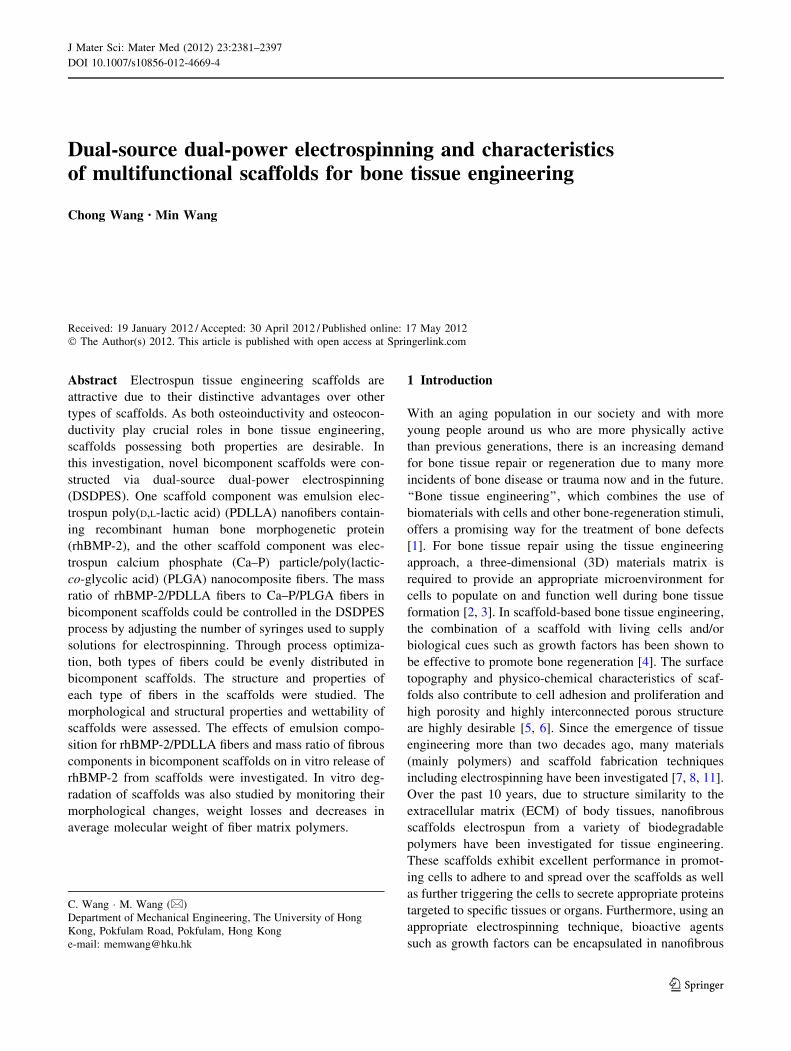
Dual-source dual-power electrospinning and characteristicsof multifunctional scaffolds for bone tissue engineering
Chong Wang • Min Wang
Received: 19 January 2012 / Accepted: 30 April 2012 / Published online: 17 May 2012
� The Author(s) 2012. This article is published with open access at Springerlink.com
Abstract Electrospun tissue engineering scaffolds are
attractive due to their distinctive advantages over other
types of scaffolds. As both osteoinductivity and osteocon-
ductivity play crucial roles in bone tissue engineering,
scaffolds possessing both properties are desirable. In
this investigation, novel bicomponent scaffolds were con-
structed via dual-source dual-power electrospinning
(DSDPES). One scaffold component was emulsion elec-
trospun poly(D,L-lactic acid) (PDLLA) nanofibers contain-
ing recombinant human bone morphogenetic protein
(rhBMP-2), and the other scaffold component was elec-
trospun calcium phosphate (Ca–P) particle/poly(lactic-
co-glycolic acid) (PLGA) nanocomposite fibers. The mass
ratio of rhBMP-2/PDLLA fibers to Ca–P/PLGA fibers in
bicomponent scaffolds could be controlled in the DSDPES
process by adjusting the number of syringes used to supply
solutions for electrospinning. Through process optimiza-
tion, both types of fibers could be evenly distributed in
bicomponent scaffolds. The structure and properties of
each type of fibers in the scaffolds were studied. The
morphological and structural properties and wettability of
scaffolds were assessed. The effects of emulsion compo-
sition for rhBMP-2/PDLLA fibers and mass ratio of fibrous
components in bicomponent scaffolds on in vitro release of
rhBMP-2 from scaffolds were investigated. In vitro deg-
radation of scaffolds was also studied by monitoring their
morphological changes, weight losses and decreases in
average molecular weight of fiber matrix polymers.
1 Introduction
With an aging population in our society and with more
young people around us who are more physically active
than previous generations, there is an increasing demand
for bone tissue repair or regeneration due to many more
incidents of bone disease or trauma now and in the future.
‘‘Bone tissue engineering’’, which combines the use of
biomaterials with cells and other bone-regeneration stimuli,
offers a promising way for the treatment of bone defects
[1]. For bone tissue repair using the tissue engineering
approach, a three-dimensional (3D) materials matrix is
required to provide an appropriate microenvironment for
cells to populate on and function well during bone tissue
formation [2, 3]. In scaffold-based bone tissue engineering,
the combination of a scaffold with living cells and/or
biological cues such as growth factors has been shown to
be effective to promote bone regeneration [4]. The surface
topography and physico-chemical characteristics of scaf-
folds also contribute to cell adhesion and proliferation and
high porosity and highly interconnected porous structure
are highly desirable [5, 6]. Since the emergence of tissue
engineering more than two decades ago, many materials
(mainly polymers) and scaffold fabrication techniques
including electrospinning have been investigated [7, 8, 11].
Over the past 10 years, due to structure similarity to the
extracellular matrix (ECM) of body tissues, nanofibrous
scaffolds electrospun from a variety of biodegradable
polymers have been investigated for tissue engineering.
These scaffolds exhibit excellent performance in promot-
ing cells to adhere to and spread over the scaffolds as well
as further triggering the cells to secrete appropriate proteins
targeted to specific tissues or organs. Furthermore, using an
appropriate electrospinning technique, bioactive agents
such as growth factors can be encapsulated in nanofibrous
C. Wang � M. Wang (&)
Department of Mechanical Engineering, The University of Hong
Kong, Pokfulam Road, Pokfulam, Hong Kong
e-mail: [email protected]
123
J Mater Sci: Mater Med (2012) 23:2381–2397
DOI 10.1007/s10856-012-4669-4

scaffolds [9, 10], with the resultant scaffolds mimicking the
role of ECM on the storage and release of bio-signals
secreted by cells which triggers further cell proliferation
and differentiation.
For bone tissue engineering, biodegradable polymers
[12–14], bioceramics [15, 16] and composites [17, 18] have
been fabricated into scaffolds. From the material point of
view, bone ECM consists of an organic matrix (mainly
collagen) and inorganic, nanosized bone apatite crystals
which are arranged in a hierarchical structure [17]. Due to
chemical similarity to bone apatite, synthetic, osteocond-
cutive calcium phosphates are widely used to repair bone
defects and bone can be formed in direct contact with these
ceramics [19]. The incorporation of calcium phosphate
(Ca–P) bioceramics in materials such as polymers to form
composites is shown to assist bone mineralization [20, 21].
For bone tissue engineering, it is therefore natural to form
electrospun composite scaffolds comprising of a degrad-
able biopolymer and bioactive (osteoconductive) Ca–P
nanoparticles [22, 23]. The Ca–P nanoparticles incorpo-
rated will render the scaffolds osteoconductive, facilitating
osteoblastic cell proliferation and differentiation as well as
calcification of bone matrix [24].
Because biological cues play important roles in bone
tissue regeneration, controlled delivery of growth factors or
other biomolecules in the scaffolds are considered key fac-
tors in bone tissue engineering [25, 26]. Growth factors
secreted by cells significantly influence different cellular
events such as cell adhesion, proliferation and differentia-
tion. Among various growth factors, bone morphogenetic
proteins 2 (BMP-2) is generally regarded as the most
potent growth factor for bone formation, especially in the
osteogenic differentiation of mesenchymal stem cells to
osteoblasts [27, 28]. Due to the high surface area-to-volume
ratio, electrospun nanofibers are considered excellent vehi-
cles for the storage and controlled release of growth factors.
As electrospinning of simple blends of BMP-2 and polymer
solutions results in low encapsulation efficiency and high
burst release of BMP-2 and risks BMP-2 denaturation,
emulsion electrospinning, which can produce core–shell
structured fibers, appears to be suitable for constructing tis-
sue engineering scaffolds containing biomolecules [28].
For bone tissue engineering, our previous investigations
have shown that: (1) electrospun osteoconductive nano-
composite fibers containing carbonated hydroxyapatite
nanoparticles promoted the proliferation and differentiation
of osteoblastic cells [23]; (2) the controlled release of
recombinant BMP-2 (rhBMP-2) from scaffolds rendered
the scaffolds with desired osteoinductivity [29]. Therefore,
incorporating both Ca–P nanoparticles and rhBMP-2 mol-
ecules in electrospun scaffolds should have a synergetic
effect on cell proliferation and differentiation, accelerating
bone regeneration. By varying the amounts of Ca–P and
rhBMP-2, nanofibrous scaffolds with modulated osteo-
conductivity and osteoinductivity could be developed. In
this investigation, bicomponent scaffolds, which comprised
a rhBMP-2 encapsulated poly(D,L-lactic acid) (PDLLA)
fibrous component and an Ca–P nanoparticle incorporated
poly(lactic-co-glycolic acid) (PLGA) fibrous component,
were constructed through the use of our dual-source dual-
power electrospinning (DSDPES) technique [30, 31].
Amorphous Ca–P, which is degradable and more bioactive
than HA, was used as the bioceramic. Ca–P/PLGA com-
posite fibers were electrospun using an established proce-
dure [23] and emulsion electrospinning was employed to
incorporate rhBMP-2 in PDLLA [28]. The mass ratio of the
two fibrous components was varied in order to obtain
bicomponent scaffolds with tunable osteoconductivity and
osteoinductivity. Characteristics of electrospun mono- and
bicomponent scaffolds were subsequently studied. The in
vitro rhBMP-2 release behaviour and in vitro degradation
of scaffolds were also investigated.
2 Materials and methods
2.1 Materials
Amorphous Ca–P nanoparticles were produced in-house
using a previously established process [32]. All chemicals
used for synthesizing Ca–P nanoparticles were supplied by
reputable manufacturers and the deionized water (DI
water) for all experiments was obtained using a DI water
producer (Model D12681, Barnstead International, USA).
Poly(lactic-co-glycolic acid) (PLGA) with a LA:GA molar
ratio of 50:50 and poly(D,L-lactic acid) (PDLLA) with an
average molecular weight of 120 kDa were purchased
from Lakeshore Biomaterials, USA. Sodium dodecyl sul-
fate (SDS), Span-80 surfactant, phosphate buffered
saline (PBS) tablets and bovine serum albumin (BSA)
protein were Sigma–Aldrich products. Chloroform and
N,N-dimethylformamide (DMF) were supplied by Uni
Chem Co. Dimethyl sulfoxide (DMSO) was supplied by
Fisher Scientific Inc, USA. rhBMP-2 with a molecular
weight of 26KDa was purchased from Shanghai Rebone
Biomaterials, China. The human BMP-2 ELISA kits were
purchased from Peprotech Inc., USA. An electrical balance
with an accuracy of 0.1 mg was used for weighing mate-
rials and samples.
2.2 Methods
2.2.1 Scaffold fabrication
2.2.1.1 Emulsion formulation To construct monocom-
ponent rhBMP-2/PDLLA scaffolds (and also to produce
2382 J Mater Sci: Mater Med (2012) 23:2381–2397
123

the rhBMP-2/PDLLA fibrous component in bicomponent
scaffolds), emulsion electrospinning was used. To form
water-in-oil emulsions for emulsion electrospinning, 10 lg
of rhBMP-2 and 2 mg of BSA (as a stabilizer) were dis-
solved in 1 ml of DI water to produce the rhBMP-2 loaded
water phase. The oil phase was formed by dissolving 1.5 g
of PDLLA and 75 ll of Span-80 (the surfactant for making
emulsions, 5 wt% in respect to PDLLA) in 10 ml of
chloroform, giving a 15 % w/v polymer solution. The
uniform emulsions were produced by dripping the water
phase into the oil phase, which was followed by an ultra-
sonication treatment in an ice-water bath.
2.2.1.2 Formation of Ca–P/PLGA composite suspension
for electrospinning Nanosized Ca–P was made by rapidly
mixing an acetone solution of Ca (NO3)2�4H2O with an
aqueous solution of (NH4)2HPO4 at a molar ratio of
Ca:P = 1.5:1 using a magnetic stirrer, followed by stirring,
centrifugation and washing. The slurry of nanoprecipitates
was freeze-dried using a Labconco Free-Zone freezedrying
system to obtain dry powder [32]. The Ca–P nanoparticles
synthesized were characterized using various techniques.
X-ray diffraction (XRD) analysis was performed on an
X-ray diffractometer (Raguku Model D/max III, Japan)
using Cu Ka radiation and Ni filter. XRD patterns were
collected at room temperature over the 2h range of 20–50�at a scanning rate of 2�/min. The morphology, size and
structure of Ca–P nanoparticles were studied using a field
emission scanning electron microscope (FE-SEM, LEO
1530, Germany) and a transmission electron microscope
(FEI Tecnai G2 20 S-TWIN Scanning TEM, the Nether-
lands). The Ca:P ratio of Ca–P particles was determined
using an energy dispersive X-ray spectrometer (EDX)
attached to the TEM.
When Ca–P/PLGA suspensions were prepared for
composite fiber electrospinning, a two-step method was
used to reduce Ca–P particle agglomeration in the sus-
pensions. Briefly, 0.25 g and 1 g of PLGA were dissolved
separately in 5 ml of a mixed solvent system (chloro-
form:DMF = 4:1), forming polymer solution A and solu-
tion B, respectively. 138 mg of Ca–P nanoparticles were
subsequently added into solution A, which was followed by
a 5 min ultra-sonication treatment, producing a good dis-
persion of Ca–P nanoparticles in the PLGA solution. The
Ca–P/PLGA suspension formed was then added to solution
B, which was followed by another 5 min ultra-sonication
treatment, yielding a uniform Ca–P/PLGA suspension (at
12.5 % w/v polymer concentration) with a composition of
10 wt% Ca–P nanoparticles (in respect to the weight of
PLGA).
2.2.1.3 Fabrication of mono- and bicomponent scaffolds
through dual-source dual power (DSDP) electrospin-
ning In our previous research, to construct multicompo-
nent fibrous systems for biomedical applications, a
multiple-source electrpspinning approach was proposed
and in practice, a dual-source dual-power electrospinning
(DSDPES) technique was developed for various bicom-
ponent fibrous structures [30, 31]. In the current investi-
gation, DSDPES was employed to construct bicomponent
scaffolds containing rhBMP-2/PDLLA and Ca–P/PLGA
fibers and the experimental setup is schematically shown in
Fig. 1. The DSDPES apparatus comprised two high voltage
power supplies, two syringe pumps and a low rotation
speed drum as the fiber collector. When the two syringes,
which were loaded with an emulsion and a nanocomposite
suspension, respectively, were applied separately with high
voltages by the two high voltage power supplies, rhBMP-2/
PDLLA fibers and Ca–P/PLGA nanocomposite fibers were
electrospun simultaneously and collected by the rotating
fiber collector to form a non-woven bicomponent scaffold.
Furthermore, by varying the number of syringes used for
each electrospinning component and hence changing the
ratio of syringes between the two electrospinning sources
(e.g., from 1:1 to 1:3), the mass ratio of rhBMP-2/PDLLA
to Ca–P/PLGA fibers in bicomponent scaffolds would be
Fig. 1 Schematic diagram of
the experimental setup for dual-
source dual-power
electrospinning (DSDPES)
J Mater Sci: Mater Med (2012) 23:2381–2397 2383
123

altered, resulting possibly in different osteoconductivity-to-
osteoinductivity ratios of bicomponent scaffolds. The
stainless steel needles attached to syringes had an inner
diameter of 0.4 mm. The applied voltage, solution feeding
rate and working distance for producing rhBMP-2/PDLLA
fibers were 10 kV, 1.98 ml/h and 10 cm, respectively,
while those for electrpsoinning Ca–P/PLGA composite
fibers were 15 kV, 1.98 ml/h and 15 cm, respectively.
Table 1 summarizes the composition of bicomponent
scaffolds and monocomponent scaffolds (which acted as
controls) that were produced in this investigation.
2.2.2 Characterization of fibers and scaffolds
The surface morphology of electrospun fibers and the
structure of mono- and bicomponent scaffolds were exam-
ined using SEM. All electrospun samples for SEM examin-
ations were placed in desiccators for 48 h to remove solvents
and sputter-coated with a thin layer of gold. The average
diameter of fibers in each scaffold (or in each fibrous com-
ponent of bicomponent scaffolds) was determined by
selecting randomly 100 fibers in each SEM micrograph and
measuring their diameters with the help of a UTHSCSA
image tool (which could be downloaded freely from
http://compdent.uthscsa.edu/dig/download.html). A trans-
mission electron microscope (Philips EM208s TEM, the
Netherlands) was used to study the core–shell structure of
emulsion electrospun fibers. Samples for TEM observations
were obtained by collecting as-spun fibers on copper grids
directly. The diameter ratio between the core and the whole
fiber was determined by measuring the diameter of water
phase core and that of the whole fiber, also with the help of
the UTHSCSA image tool. Using a Nikon Eclipse TE2000-U
inverted microscope, fluorescence microscopy was con-
ducted to investigate the distribution of rhBMP-2 in emul-
sion electrospun fibers, with rhBMP-2 being labeled with
rhodamine B. Fourier transform infrared (FTIR) spectro-
scopic analysis of electrospun fibrous scaffolds was
conducted using an FTIR equipment (Spectrum BX FTIR
spectrometer from Perkin–Elmer, USA) over a range of
500–4,000 cm-1 at a resolution of 2 cm-1. To assess the
wettability, water contact angles of fibrous scaffolds were
measured on a contact angle measuring machine (SL200B,
Shanghai Solon Tech Inc Ltd, China) using the sessile drop
method with DI water as the liquid. During measurement,
square samples (10 mm 9 10 mm) were cut from electro-
spun fibrous membranes and placed on the stage of the
measuring machine. The contact angle of the water drop on
the sample surface was determined at room temperature
following a standardized procedure and using a proprietary
software. Three measurements were carried out at different
locations of the same sample and the average value was
obtained. (For comparison in the wettability study, PLGA
and PDLLA thin films were also made using the solvent
casting method. Their water contact angles were measured
using the same procedure.)
For bicomponent scaffolds produced, the mass ratio
between rhBMP-2/PDLLA fibers and Ca–P/PLGA fibers
needed to be determined or verified. Due to the structure
similarity between PDLLA and PLGA, there is no common
solvent that could be used to separate the two types of
fibers from each other by dissolving one fibrous component
while leaving the other fibrous component intact. There-
fore, two methods were used to determine the mass ratio
between the two fibrous components. With method one (the
‘‘substitution method’’), gelatin, a water soluble natural
polymer, was used in DSDPES, forming gelatin nanofibers
as a substitute for the rhBMP-2/PDLLA fibrous component
in bicomponent scaffolds, i.e., for the ‘‘substitution
method’’, bicomponent scaffolds consisting of gelatin
fibers and Ca–P/PLGA fibers were constructed via DSD-
PES. (In this investigation, for electrospinning of gelatin
fibers, gelatin was dissolved in acetic acid to form gelatin
solutions.) After DSDPES, bicomponent scaffolds formed
were placed in desiccators to remove residual solvents.
They were then immersed in DI water to remove the gelatin
Table 1 Composition of solutions and emulsions for mono- and bicomponent scaffolds
Scaffold
designation
Scaffold composition
rhBMP-2/PDLLA Component Component ratio
(in mass)
Ca–P/PLGA component
Water phase Oil phase
F1 10 lg rhBMP-2 ? 2 mg BSA/ml
1.0 ml
10 ml 15 % w/v
PDLLA polymer solution
75 ll Span-80
100:0 138 mg Ca–P nanoparticles in
10 ml 12.5 % w/v
PLGA solution
F2 0:100
F3 50:50
F4 33:66
F5 25:75
F6 0.5 ml 50:50
F7 2.0 ml 50:50
2384 J Mater Sci: Mater Med (2012) 23:2381–2397
123
fibers. The bicomponent scaffolds before and after gelatin
removal were weighed and hence the mass ratio between
rhBMP-2/PDLLA fibers and Ca–P/PLGA fibers could be
deduced. With method two (the ‘‘TGA method’’), the Ca–P
contents in mono- and bicomponent scaffolds determined
by thermogravimetric analysis (TGA) were used to calcu-
late the mass ratio between the two fibrous components. In
the TGA analysis, a thermogravimetric analyzer (Pyris 1
TGA, Perkin–Elmer, USA) was employed and tests were
conducted in flowing nitrogen (20 ml/min) environment.
(The accuracy of the balance in the TGA equipment was
0.0001 mg). Form the TGA curves obtained, the Ca–P
content of monocomponent Ca–P/PLGA scaffolds was
determined to be C0 while the Ca–P content of bicompo-
nent scaffolds was C. The mass ratio between the two
fibrous components (W1:W2) for bicomponent scaffolds
was calculated using the equation below (W1 being the
weight of rhBMP-2/PDLLA fibers and W2 being the weight
of Ca–P/PLGA fibers):
W1
W2
¼ 1� C=C0
C=C0
ð1Þ
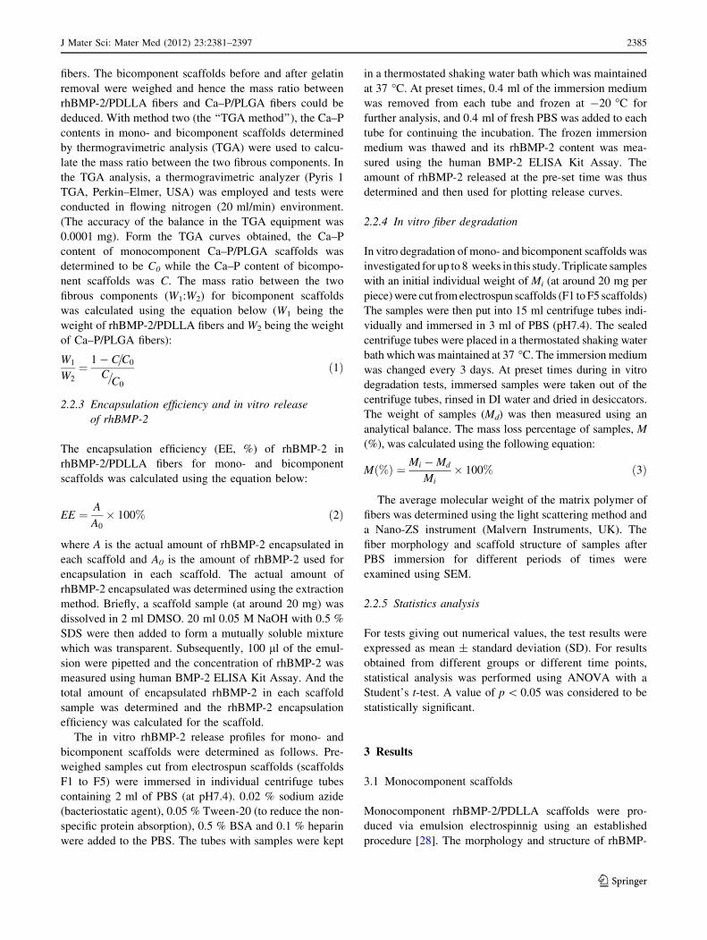
2.2.3 Encapsulation efficiency and in vitro release
of rhBMP-2
The encapsulation efficiency (EE, %) of rhBMP-2 in
rhBMP-2/PDLLA fibers for mono- and bicomponent
scaffolds was calculated using the equation below:
EE ¼ A
A0
� 100% ð2Þ
where A is the actual amount of rhBMP-2 encapsulated in
each scaffold and A0 is the amount of rhBMP-2 used for
encapsulation in each scaffold. The actual amount of
rhBMP-2 encapsulated was determined using the extraction
method. Briefly, a scaffold sample (at around 20 mg) was
dissolved in 2 ml DMSO. 20 ml 0.05 M NaOH with 0.5 %
SDS were then added to form a mutually soluble mixture
which was transparent. Subsequently, 100 ll of the emul-
sion were pipetted and the concentration of rhBMP-2 was
measured using human BMP-2 ELISA Kit Assay. And the
total amount of encapsulated rhBMP-2 in each scaffold
sample was determined and the rhBMP-2 encapsulation
efficiency was calculated for the scaffold.
The in vitro rhBMP-2 release profiles for mono- and
bicomponent scaffolds were determined as follows. Pre-
weighed samples cut from electrospun scaffolds (scaffolds
F1 to F5) were immersed in individual centrifuge tubes
containing 2 ml of PBS (at pH7.4). 0.02 % sodium azide
(bacteriostatic agent), 0.05 % Tween-20 (to reduce the non-
specific protein absorption), 0.5 % BSA and 0.1 % heparin
were added to the PBS. The tubes with samples were kept
in a thermostated shaking water bath which was maintained
at 37 �C. At preset times, 0.4 ml of the immersion medium
was removed from each tube and frozen at -20 �C for
further analysis, and 0.4 ml of fresh PBS was added to each
tube for continuing the incubation. The frozen immersion
medium was thawed and its rhBMP-2 content was mea-
sured using the human BMP-2 ELISA Kit Assay. The
amount of rhBMP-2 released at the pre-set time was thus
determined and then used for plotting release curves.
2.2.4 In vitro fiber degradation
In vitro degradation of mono- and bicomponent scaffolds was
investigated for up to 8 weeks in this study. Triplicate samples
with an initial individual weight of Mi (at around 20 mg per
piece) were cut from electrospun scaffolds (F1 to F5 scaffolds)
The samples were then put into 15 ml centrifuge tubes indi-
vidually and immersed in 3 ml of PBS (pH7.4). The sealed
centrifuge tubes were placed in a thermostated shaking water
bath which was maintained at 37 �C. The immersion medium
was changed every 3 days. At preset times during in vitro
degradation tests, immersed samples were taken out of the
centrifuge tubes, rinsed in DI water and dried in desiccators.
The weight of samples (Md) was then measured using an
analytical balance. The mass loss percentage of samples, M
(%), was calculated using the following equation:
Mð%Þ ¼ Mi �Md
Mi� 100% ð3Þ
The average molecular weight of the matrix polymer of
fibers was determined using the light scattering method and
a Nano-ZS instrument (Malvern Instruments, UK). The
fiber morphology and scaffold structure of samples after
PBS immersion for different periods of times were
examined using SEM.
2.2.5 Statistics analysis
For tests giving out numerical values, the test results were
expressed as mean ± standard deviation (SD). For results
obtained from different groups or different time points,
statistical analysis was performed using ANOVA with a
Student’s t-test. A value of p \ 0.05 was considered to be
statistically significant.
3 Results
3.1 Monocomponent scaffolds
Monocomponent rhBMP-2/PDLLA scaffolds were pro-
duced via emulsion electrospinnig using an established
procedure [28]. The morphology and structure of rhBMP-
J Mater Sci: Mater Med (2012) 23:2381–2397 2385
123
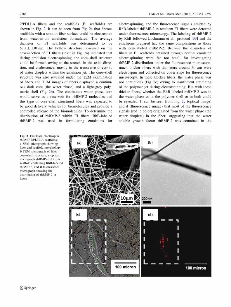
2/PDLLA fibers and the scaffolds (F1 scaffolds) are
shown in Fig. 2. It can be seen from Fig. 2a that fibrous
scaffolds with a smooth fiber surface could be electrospun
from water-in-oil emulsions formulated. The average
diameter of F1 scaffolds was determined to be
570 ± 130 nm. The hollow structure observed on the
cross-section of F1 fibers (inset in Fig. 2a) indicated that
during emulsion electrospinning, the core–shell structure
could be formed owing to the stretch, in the axial direc-
tion, and coalescence, mostly in the transverse direction,
of water droplets within the emulsion jet. The core–shell
structure was also revealed under the TEM examination
of fibers and TEM images of fibers displayed a continu-
ous dark core (the water phase) and a light-grey poly-
meric shell (Fig. 2b). The continuous water phase core
would serve as a reservoir for rhBMP-2 molecules and
this type of core–shell structured fibers was expected to
be good delivery vehicles for biomolecules and provide a
controlled release of the biomolecules. To determine the
distribution of rhBMP-2 within F1 fibers, RhB-labeled
rhBMP-2 was used in formulating emulsions for
electrospinning, and the fluorescence signals emitted by
RhB-labeled rhBMP-2 in resultant F1 fibers were detected
under fluorescence microscopy. The labeling of rhBMP-2
by RhB followed Lochmann et al.’ protocol [33] and the
emulsions prepared had the same compositions as those
with non-labeled rhBMP-2. Because the diameters of
fibers in F1 scaffolds obtained through normal emulsion
electrospinning were far too small for investigating
rhBMP-2 distribution under the fluorescence microscope,
much thicker fibers with diameters around 30 lm were
electrospun and collected on cover slips for fluorescence
microscopy. In these thicker fibers, the water phase was
not continuous (Fig. 2c) owing to insufficient stretching
of the polymer jet during electrospinning. But with these
thicker fibers, whether the RhB-labeled rhBMP-2 was in
the water phase or in the polymer shell or in both could
be revealed. It can be seen from Fig. 2c (optical image)
and d (fluorescence image) that most of the fluorescence
signals (red in color) originated from the water phase (the
water droplets) in the fiber, suggesting that the water
soluble growth factor rhBMP-2 was contained in the
Fig. 2 Emulsion electrospun
rhBMP-2/PDLLA scaffolds:
a SEM micrograph showing
fiber and scaffold morphology,
b TEM micrograph of fiber
core–shell structure, c optical
micrograph rhBMP-2/PDLLA
scaffold containing RhB-labeled
rhBMP-2, and d fluorescence
micrograph showing the
distribution of rhBMP-2 in
fibers
2386 J Mater Sci: Mater Med (2012) 23:2381–2397
123

water phase and well protected by the DI water from the
polymer solution during the electrospinning process.
To fabricate Ca–P/PLGA nanocomposite scaffolds,
Ca–P nanoparticles were made and their morphology and
structure were studied. It can be seen from Fig. 3a and b
that the Ca–P nanoparticles produced in-house were
spherical in shape and had diameters around 30 nm. Both
selected area diffraction (SAD) patterns obtained through
TEM (inset in Fig. 3b) and XRD patterns (Fig. 3d) indi-
cated that the Ca–P nanoparticles were in the amorphous
state. EDX spectra obtained during TEM analysis of Ca–P
nanoparticles revealed the presence of Ca, P, O, Cu and C
(Fig. 3c). The Cu and C peaks arose from the Cu grid
which was used for holding Ca–P nanoparticulate samples
for TEM examinations and the Cu grid was covered with a
C film. O was contained in Ca–P particles. Ca and P were
dominant peaks on EDX spectra. The atomic ratio between
Ca and P determined in EDX was 1.48 (Fig. 3c), which
was close to that of tricalcium phosphate (TCP, with a Ca:P
ratio of 1.5). The morphology and structure Ca–P/PLGA
nanocomposite fibers and scaffolds (F2 scaffolds) were
studied. It can be seen from Fig. 3e that with a fiber
nominal composition of 10 wt% Ca–P nanoparticles,
Ca–P/PLGA nanocomposite scaffolds with a fiber diameter
of 1,140 ± 170 nm could be successfully fabricated. The
Ca–P nanoparticles were mainly incorporated in the fibers
(inset in Fig. 3e) and a small number of Ca–P nanoparticles
were embedded near the fiber surface, resulting in a rela-
tively rough fiber surface. TEM analysis indicated that the
incorporated Ca–P nanoparticles had a good dispersion in
the fibers (Fig. 3f, the dark particles in the polymer matrix
of fibers). TGA analysis of F2 scaffolds showed that the
actual Ca–P content of Ca–P/PLGA nanocomposite fibers
was 9.5 ± 0.3 %, which was very close to the nominal
Ca–P content.
3.2 Bicomponent scaffolds
DSDPES for fabricating bicomponent scaffolds is sche-
matically illustrated by Fig. 1 and the morphology of
electrospun scaffolds (F1 to F5 scaffolds, which were
produced using the same electrospinning parameters but
differed in the fiber component ratios) is shown in Fig. 4.
The SEM micrographs (Fig. 4a–e) indicated that with our
DSDPES experimental setup and procedure, the two types
of fibers could be evenly distributed in bicomponent scaf-
folds and that when the mass ratio between the two fibrous
components was varied by changing the number of the
Fig. 3 Ca–P nanoparticles and electrospun Ca–P/PLGA nanocom-
posite scaffolds: a SEM micrograph of Ca–P nanoparticles, b TEM
micrograph and SAD pattern of Ca–P nanoparticles, c EDX spectrum
of Ca–P nanoparticles, d XRD pattern of Ca–P nanoparticles, e SEM
micrograph showing fiber and scaffold morphology, and f TEM
micrograph of nanocomposite fiber structure
J Mater Sci: Mater Med (2012) 23:2381–2397 2387
123
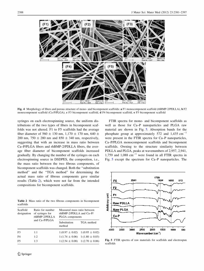
syringes on each electrospinning source, the uniform dis-
tributions of the two types of fibers in bicomponent scaf-
folds was not altered. F1 to F5 scaffolds had the average
fiber diameter of 560 ± 130 nm, 1,170 ± 170 nm, 640 ±
200 nm, 750 ± 280 nm and 850 ± 340 nm, respectively,
suggesting that with an increase in mass ratio between
Ca–P/PLGA fibers and rhBMP-2/PDLLA fibers, the aver-
age fiber diameter of bicomponent scaffolds increased
gradually. By changing the number of the syringes on each
electrospinning source in DSDPES, the composition, i.e.,
the mass ratio between the two fibrous components, of
bicomponent scaffolds was changed. Both the ‘‘substitution
method’’ and the ‘‘TGA method’’ for determining the
actual mass ratio of fibrous components gave similar
results (Table 2), which were not far from the intended
compositions for bicomponent scaffolds.
FTIR spectra for mono- and bicomponent scaffolds as
well as those for Ca–P nanoparticles and PLGA raw
material are shown in Fig. 5. Absorption bands for the
phosphate group at approximately 572 and 1,435 cm-1
were present in the FTIR spectra for Ca–P nanoparticles,
Ca–P/PLGA monocomponent scaffolds and bicomponent
scaffolds. Owning to the structure similarity between
PDLLA and PLGA, peaks at wavenumbers of 2,957, 2,941,
1,759 and 1,088 cm-1 were found in all FTIR spectra in
Fig. 5 except the spectrum for Ca–P nanoparticles. The
Fig. 4 Morphology of fibers and porous structure of mono- and bicomponent scaffolds: a F1 monocomponent scaffold (rhBMP-2/PDLLA), b F2
monocomponent scaffold (Ca-P/PLGA), c F3 bicomponent scaffold, d F4 bicomponent scaffold, e F5 bicomponent scaffold
Table 2 Mass ratio of the two fibrous components in bicomponent
scaffolds
Scaffold
designation
Ratio for number
of syringes for
rhBMP-2/PDLLA
and Ca–P/PLGA
Measured mass ratio between
rhBMP-2/PDLLA and Ca–P/
PLGA components
Substitution
method
TGA method
F3 1:1 1:(0.97 ± 0.02) 1:(0.95 ± 0.02)
F4 1:2 1:(1.74 ± 0.06) 1:(1.80 ± 0.03)
F5 1:3 1:(2.54 ± 0.08) 1:(2.70 ± 0.06) Fig. 5 FTIR spectra of raw materials for scaffolds and electrospun
scaffolds
2388 J Mater Sci: Mater Med (2012) 23:2381–2397
123

peaks appearing at 2,957 and 2,941 cm-1 could be attrib-
uted to asymmetric stretching vibration and symmetric
stretching vibration of C–H. Peaks at 2,356 cm-1 could be
assigned to the asymmetric stretching (m3 mode) of CO2.
And the peaks appearing at 1,759, 1,634 and 1,088 cm-1
could be attributed to C=O stretching vibration, C=O
stretching vibration and C–O stretching vibration, respec-
tively. Compared to the spectra for raw materials, no FTIR
peak shift was found for PLGA and PDLLA fibers in
electrospun scaffolds.
The wettability of electrospun fibrous scaffolds plays an
important role in the biological performances of scaffolds,
affecting cell attachment, adhesion and proliferation, and
was thus characterized by measuring the water contact
angle in this investigation. Figure 6 displays the results
obtained: the contact angle measurements, and the contact
angle images. Scaffolds electrospun from PDLLA or
PLGA polymer solutions exhibited very high water contact
angles (135.0 ± 4.5� and 133.0 ± 3.3�, respectively),
which were much larger than those of polymeric films
produced by the solvent-cast method. This phenomenon
was also reported by other researchers [34, 35]. With the
incorporation of 10wt% of Ca–P nanoparticles, Ca–P/
PLGA nanocomposite scaffolds had a slightly lower water
contact angle than PLGA polymer scaffolds. For the two
types of monocomponent scaffolds, emulsion electrospun
F1 scaffolds were hydrophilic with a water contact angle of
85.4 ± 4.3� whereas nanocomposite F2 scaffolds were
hydrophobic with a water contact angle of 127.7 ± 3.6�.
The bicomponent scaffolds were all hydrophobic and with
an increase in the amount of Ca–P/PLGA nanocomposite
fibers, the water contact angle of biocomponent scaffolds
increased gradually.
3.3 Encapsulation and in vitro release of rhBMP-2
The encapsulation efficiency (EE) of rhBMP-2 was deter-
mined for mono- and bicomponent scaffolds using Eq. (1).
Scaffolds F1, F3, F4 and F5 had the rhBMP-2 encapsula-
tion efficiency of 86.4 ± 3.2 %, 88.4 ± 2.8 %, 85.6 ± 3.4
% and 86.7 ± 2.1 %, respectively, and no significant dif-
ference was found (p [ 0.05) among the scaffolds, sug-
gesting that in this investigation, the EE value of rhBMP-2
was not affected by the variation of bicomponent scaffold
composition (the component ratio).
The in vitro rhBMP-2 release curves for mono- and
bicomponent scaffolds are shown in Fig. 7. The in vitro
release amounts of rhBMP-2 from bicomponent scaffolds
with different component ratios were clearly different over
the release test period of 32 days (Fig. 7a). After 32 days of
in vitro release, the ratios of the released amount of rhBMP-2
from F3, F4 and F5 scaffolds (at 55.4 ± 3.2, 34.3 ± 2.5 and
22.6 ± 2.7 ng) to the released amount from F1 scaffolds (at
108.5 ± 4.3 ng) was 1:(1.97 ± 0.31), 1:(3.12 ± 0.51) and
Fig. 6 Water contact angle of electrospun scaffolds and solvent-cast
films
Fig. 7 In vitro release behaviour of rhBMP-2 from mono- and
bicomponent scaffolds: a cumulative release amount with time,
b cumulative release percentage with time
J Mater Sci: Mater Med (2012) 23:2381–2397 2389
123
1:(4.70 ± 0.50), following the same trend as that of the mass
ratio of the rhBMP-2/PDLLA component to the total
bicomponent scaffolds [1:(0.97 ± 0.02), 1:(1.74 ± 0.06)
and 1:(2.54 ± 0.08), respectively]. These results suggested
that using DSDPES and controlling the fibrous component
ratio, scaffolds with different rhBMP-2 loading and hence
different rhBMP-2 release amount (during release and at the
end of release) could be achieved, tailoring the release dos-
age for individual clinical applications. To further study the
release behaviour, the release curves were also plotted in
terms of release percentage for the test period (Fig. 7b). In
plotting these cumulative in vitro release curves for rhBMP-
2, the actual amounts of rhBMP-2 encapsulated in respective
types of scaffolds were used as 100 % and the amounts of
cumulatively released rhBMP-2 from scaffolds at the time
points were divided by the actual encapsulated amounts. It
was evident that for F1, F3, F4 and F5 scaffolds, there was an
initial burst release within the first 24 h, followed by a much
slower and sustained release of rhBMP-2. At 24 h, the initial
burst release from F1 scaffolds (the monocomponent
rhBMP-2/PDLLA scaffolds) led to a cumulative release
level of 27.0 ± 0.7 % of the rhBMP-2 encapsulated, which
was slightly higher than the release levels of 20.3 ± 1.5 % to
26.2 ± 1.4 % exhibited by bicomponent scaffolds. After
32 days, the cumulative release of rhBMP-2 reached the
39.2 ± 3.7 % (108.5 ± 4.3 ng) level for F1 scaffolds while
the release levels of 37.5 ± 2.3 %, 36.8 ± 2.2 % and
35.7 ± 2.0 % were found for F3, F4 and F5 scaffolds (the
bicomponent scaffolds) (p [ 0.05), respectively, indicating
that the release of rhBMP-2 was independent of the com-
ponent ratio of bicomponent scaffolds.
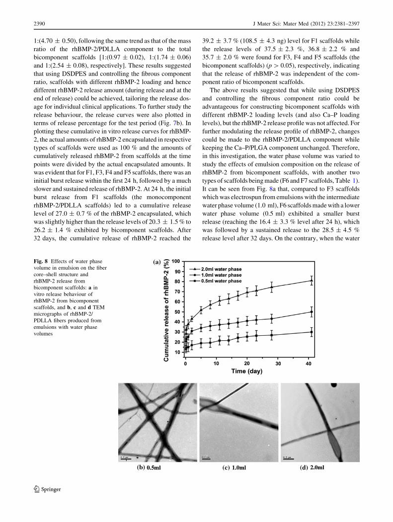
The above results suggested that while using DSDPES
and controlling the fibrous component ratio could be
advantageous for constructing bicomponent scaffolds with
different rhBMP-2 loading levels (and also Ca–P loading
levels), but the rhBMP-2 release profile was not affected. For
further modulating the release profile of rhBMP-2, changes
could be made to the rhBMP-2/PDLLA component while
keeping the Ca–P/PLGA component unchanged. Therefore,
in this investigation, the water phase volume was varied to
study the effects of emulsion composition on the release of
rhBMP-2 from bicomponent scaffolds, with another two
types of scaffolds being made (F6 and F7 scaffolds, Table 1).
It can be seen from Fig. 8a that, compared to F3 scaffolds
which was electrospun from emulsions with the intermediate
water phase volume (1.0 ml), F6 scaffolds made with a lower
water phase volume (0.5 ml) exhibited a smaller burst
release (reaching the 16.4 ± 3.3 % level after 24 h), which
was followed by a sustained release to the 28.5 ± 4.5 %
release level after 32 days. On the contrary, when the water
Fig. 8 Effects of water phase
volume in emulsion on the fiber
core–shell structure and
rhBMP-2 release from
bicomponent scaffolds: a in
vitro release behaviour of
rhBMP-2 from bicomponent
scaffolds, and b, c and d TEM
micrographs of rhBMP-2/
PDLLA fibers produced from
emulsions with water phase
volumes
2390 J Mater Sci: Mater Med (2012) 23:2381–2397
123

phase volume was raised to a higher level (2.0 ml) in
emulsions for electrospinning the F7 scaffolds, a larger burst
release that reached the 30.2 ± 4.4 % release level at 24 h
was observed for F7 scaffolds, which was followed by a
sustained release to the 55.7 ± 5.2 % release level after
32 days. TEM examination of rhBMP-2/PDLLA fibers in
F3, F6 and F7 scaffolds showed that increasing the water
phase volume in emulsions would increase the continuity of
the core and also the ratio between the diameter of the core
and the whole fiber of emulsion electrospun fibers (Fig. 8b).
For instance, when the water phase volume increased from
0.5 to 1.0 ml and 2.0 ml, the core diameter-to-fiber diameter
ratio increased significantly from 1:(5.6 ± 0.4) to 1:(3.1 ±
0.3) and further to 1:(2.0 ± 0.2) (p \ 0.05). The variation of
shell thickness in core–shell structured fibers would affect
the rhBMP-2 release behaviour. In a parallel research, our
experiments demonstrated that increasing the polymer con-
centration in emulsions would lead to smaller burst release as
well as reduced burst release level at 24 h and the total
release amount at 32 days.
3.4 In vitro scaffold degradation
The mass loss of scaffolds (F1 to F5 scaffolds) during the
in vitro degradation test period was monitored and the
results are summarized in Fig. 9a. All scaffolds exhibited
an increased mass loss with increasing incubation time.
After 4 weeks in vitro degradation, F1 scaffolds had only
3.1 ± 0.6 % mass loss, less than that of other scaffolds
(7.5 ± 1.0, 8.0 ± 1.0, 8.2 ± 0.9 and 8.7 ± 0.9 % for F3,
F4, F5 and F2 scaffolds, respectively). After 8 weeks in
vitro degradation, the mass loss between F1, F3, F4, F5 and
F2 scaffolds was significant (p \ 0.05). F2 scaffolds
exhibited a high mass loss of 35.3 ± 3.3 % after 8 weeks
while F1 scaffolds only had a 7.0 ± 1.1 % mass loss. And
bicomponent scaffolds (F3 to F5 scaffolds) having a higher
proportion of the Ca–P/PLGA fibrous component showed a
larger mass loss, but the mass loss was not proportional to
the mass ratio between Ca–P/PLGA fibers and rhBMP-2/
PDLLA fibers. The results indicated that by adjusting the
component ratio, the degradation behavior of bicomponent
scaffolds may be controlled.
The decrease in molecular weight was also monitored for
monocomponent F1 and F2 scaffolds, neat PDLLA scaf-
folds, neat PLGA scaffolds and raw polymers (PDLLA and
PLGA). It can be seen from Fig. 9b that statistically there
was no difference among as-fabricated F1 scaffolds, neat
PDLLA scaffolds and raw PDLLA polymer for the polymer
average molecular weight (at the time point of 0 week),
indicating that the short emulsion preparation process and
electrospinning process did not have a negative effect on the
average molecular weight of emulsion electrospun scaffold.
The average molecular weight was not statistically different
among the raw PLGA polymer, neat PLGA scaffolds and as-
fabricated F2 scaffolds either. After 4 and 8 weeks in vitro
degradation, F1 scaffolds (with PDLLA as the matrix for
fibers) exhibited only small reductions in average molecular
weight (from 112.0 ± 6.2 kDa to 97.0 ± 6.4 kDa and
88.0 ± 4.4 kDa). When comparing the average molecular
weight between F1 scaffolds and neat PDLLA scaffolds (the
control) over the degradation test period, no significant dif-
ference was found. In comparison, F2 scaffolds showed
significant reductions in average molecular weight (from
112.0 ± 6.5 kDa to 72.0 ± 7.2 kDa and 43.0 ± 5.3 kDa)
after 4 and 8 weeks in vitro degradation. Furthermore, the
decrease in average molecular weight of F2 scaffolds (with
PLGA as the matrix for fibers) was less than that of neat
PLGA scaffolds.
The morphology and porous structure of mono- and
bicomponent scaffolds (F1 to F5 scaffolds) were examined
under SEM at different time points during in vitro degra-
dation tests. As shown in Fig. 10, after 4 weeks immersion
in PBS at 37 �C, the fiber diameter of all scaffolds (F1 to
Fig. 9 In vitro degradation of mono- and bicomponent scaffolds.
a Weight loss of scaffolds, and b decrease in average molecular
weight of fiber polymer matrix
J Mater Sci: Mater Med (2012) 23:2381–2397 2391
123
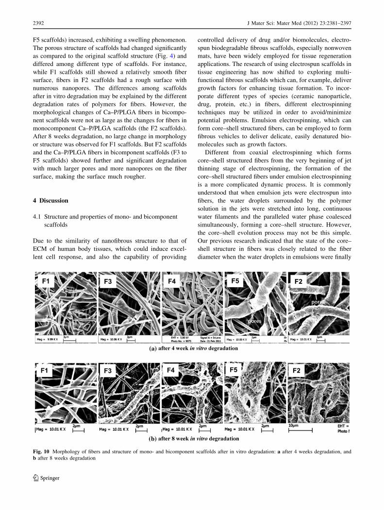
F5 scaffolds) increased, exhibiting a swelling phenomenon.
The porous structure of scaffolds had changed significantly
as compared to the original scaffold structure (Fig. 4) and
differed among different type of scaffolds. For instance,
while F1 scaffolds still showed a relatively smooth fiber
surface, fibers in F2 scaffolds had a rough surface with
numerous nanopores. The differences among scaffolds
after in vitro degradation may be explained by the different
degradation rates of polymers for fibers. However, the
morphological changes of Ca–P/PLGA fibers in bicompo-
nent scaffolds were not as large as the changes for fibers in
monocomponent Ca–P/PLGA scaffolds (the F2 scaffolds).
After 8 weeks degradation, no large change in morphology
or structure was observed for F1 scaffolds. But F2 scaffolds
and the Ca–P/PLGA fibers in bicomponent scaffolds (F3 to
F5 scaffolds) showed further and significant degradation
with much larger pores and more nanopores on the fiber
surface, making the surface much rougher.
4 Discussion
4.1 Structure and properties of mono- and bicomponent
scaffolds
Due to the similarity of nanofibrous structure to that of
ECM of human body tissues, which could induce excel-
lent cell response, and also the capability of providing
controlled delivery of drug and/or biomolecules, electro-
spun biodegradable fibrous scaffolds, especially nonwoven
mats, have been widely employed for tissue regeneration
applications. The research of using electrospun scaffolds in
tissue engineering has now shifted to exploring multi-
functional fibrous scaffolds which can, for example, deliver
growth factors for enhancing tissue formation. To incor-
porate different types of species (ceramic nanoparticle,
drug, protein, etc.) in fibers, different electrospinning
techniques may be utilized in order to avoid/minimize
potential problems. Emulsion electrospinning, which can
form core–shell structured fibers, can be employed to form
fibrous vehicles to deliver delicate, easily denatured bio-
molecules such as growth factors.
Different from coaxial electrospinning which forms
core–shell structured fibers from the very beginning of jet
thinning stage of electrospinning, the formation of the
core–shell structured fibers under emulsion electrospinning
is a more complicated dynamic process. It is commonly
understood that when emulsion jets were electrospun into
fibers, the water droplets surrounded by the polymer
solution in the jets were stretched into long, continuous
water filaments and the paralleled water phase coalesced
simultaneously, forming a core–shell structure. However,
the core–shell evolution process may not be this simple.
Our previous research indicated that the state of the core–
shell structure in fibers was closely related to the fiber
diameter when the water droplets in emulsions were finally
Fig. 10 Morphology of fibers and structure of mono- and bicomponent scaffolds after in vitro degradation: a after 4 weeks degradation, and
b after 8 weeks degradation
2392 J Mater Sci: Mater Med (2012) 23:2381–2397
123
converted into the continuous water phase core of solidified
fibers. In our investigation, the water droplets in emulsions
had an initial diameter of 3–5 lm; however, after the
stretching induced by electrospinning, numerous water
droplets with much smaller diameter (about 100–200 nm)
were formed. This was because when electrospinning
started, the spherical water droplets in emulsions under-
went simultaneous deformation and became elliptical water
droplets or longer but thinner water columns. Once the
electricstatic force was above a critical value, elliptical
water droplets and/or thin water columns would break up
into a string of smaller water droplets. This breakup phe-
nomenon could be explained by Rayleigh/capillary insta-
bility, which was often encountered in immiscible fluid
systems, and determined by several factors such as vis-
cosity ratio between the water phase and oil phase, radius
of the water phase, interfacial tension, etc. Different from
closed biphasic fluid systems, fibers made by electrospin-
ning underwent rapid solvent evaporation; therefore, the
real-time shape variations of the water phase within fibers
could be ‘‘frozen’’ by the solidified shell layer. Due to the
slow velocity of solvent ventilating from thick fibers,
deformed water droplets or instable water columns had
sufficient time to break up into smaller droplets; whereas in
very thin fibers, much quicker solvent ventilating resulted
in the solidification of the shell layer before the breakup of
the water phase, forming a longer and more continuous
water phase core. In the meantime, the coalescence of
parallel water droplets and water filaments in the transverse
direction of fibers during solidification of emulsion jets was
also found to be affected by the fiber diameter: a larger
extent of water phase coalescence occurred in thinner fibers
rather than in thick fibers. The inward movement of the
water phase to the center of fibers could be explained by (1)
dielectrophoresis, which contributes to the mutual attrac-
tion between electriferous water droplets, and (2) the
‘‘evaporation and stretching induced de-emulsification’’
theory, which pointed out that the viscosity difference
between the water droplets and polymer solution in emul-
sion jets would direct the water phase to settle into the
interior of fibers instead of on the fiber surface [28]. The
above discussions suggest that the fiber diameter had
played a key role in determining the state of the core–shell
structure in emulsion electrospun fibers, and both the fiber
diameter and the state of the core–shell structure would
have significant effects on the release profile of biomole-
cules encapsulated. In this investigation, ultrafine PDLLA
emulsion electrospun fibers (with a diameter of 570 ±
130 nm) were obtained, which had a single water phase
core and a continuous core–shell structure, and hence were
employed as a delivery vehicle for rhBMP-2.
The cell adhesion and growth on a material surface or a
scaffold is strongly influenced by the substrate wettability.
Many studies have suggested that cells adhere, spread and
grow more easily on moderately hydrophilic substrates
than on hydrophobic or very hydrophilic substrates [36].
Results from our wettability tests showed that compared to
flat, non-porous films made by the solvent-casting method,
fibrous scaffolds fabricated by electrospinning had much
larger water contact angles. This phenomenon was caused
by the rough surface of scaffolds. On fibrous scaffolds, the
test water droplet could not easily penetrate into inter-fiber
pores in the rough surface of hydrophobic fibrous mem-
branes. Therefore, the water droplet was merely supported
on a semi-solid and semi-air plane surface, resulting in a
significant increase in the water contact angle. A similar
observation was made by Ma et al. [35] who found that the
water contact angle of electrospun polyethylene tere-
phthalate (PET) fibrous membranes was significantly larger
than that of PET film. Furthermore, it was also reported
that scaffolds electrospun from emulsions formulated with
the help of a surfactant had much smaller water contact
angle [37], and this was similarly observed in our investi-
gation. For the electrospun Ca–P/PLGA scaffolds, the
incorporation of Ca–P nanoparticles reduced the water
contact angle, thus improving the scaffold wettability. This
was similarly observed for composite scaffolds incorpo-
rated with other nano-sized bioceramic particles [23]. The
affinity of calcium phosphate bioceramics (in either bulk or
particulate form) to water contributed to the improved
wettability of composite scaffolds containing bioceramic
nanoparticles.
In the current study, to form bicomponent scaffolds with
different mass ratios of the two components, multiple
syringes connected with individual needles were used as
the solution supplies for electrospinning the Ca–P/PLGA
fibrous component. By applying a high voltage on the
needles of parallel syringes, nanocomposite suspension jets
were ejected, which subsequently formed the Ca–P/PLGA
fibrous component in bicomponent scaffolds (F2 to F5
scaffolds). SEM micrographs in Fig. 3f show that the
Ca–P/PLGA fibers were evenly distributed in the bicom-
ponent scaffolds, indicating the success of the DSDPES
technique and the multiple-syringe strategy for varying the
composition of bicomponent scaffolds. Results listed in
Table 2 suggest that using the DSDPES technique and our
experimental setup, the composition of bicomponent scaf-
folds could be controlled. There were slight differences
between nominal compositions and measured, real com-
positions of bicomponent scaffolds, which were mainly due
to electrostatic repulsion induced fiber loss. (The electro-
static repulsion problem, which is a general issue in the
electrospinning field, is tackled currently by our investi-
gations into a new electrospinning technique.) In future
studies, through the minor adjustment of number of
syringes, intended compositions for bicomponent scaffolds
J Mater Sci: Mater Med (2012) 23:2381–2397 2393
123

could be achieved. An empirical relationship could be
established between the number of syringes (as solution
supplies) and composition of bicomponent scaffolds [30, 31].
4.2 In vitro release behavior of rhBMP-2 from
mono- and bicomponent scaffolds
Because months are needed for bone tissue regeneration in
the body, employing PDLLA as the polymer matrix for
rhBMP-2/PDLLA fibers could achieve a prolonged release
of rhBMP-2. In this investigation, a sustained release of
rhBMP-2 following an initial burst release was found for
scaffolds containing rhBMP-2/PDLLA fibers. As discussed
in the previous section on the formation of core–shell
structured fibers during emulsion electrospinning, the
inward movement of water droplets played a crucial role in
forming the core–shell structure. Although the majority of
water droplets could move inward to achieve their coales-
cence in the interior of fibers, the rest of them which were on
or close to the surface of the emulsion jet initially may be
stayed away from the fiber core due to rapid solvent evapo-
ration, forming pockets of encapsulated rhBMP-2 near fiber
surface. Therefore, rhBMP-2 localized on these sites would
initially diffused out of fibers because these close-to-surface
pockets had very thin shells which favored rhBMP-2 diffu-
sion, resulting in its burst release. Owing to the slow deg-
radation of PDLLA in scaffold, after the initial burst release,
all scaffolds exhibited a slow but sustained release of
rhBMP-2 at a constant rate up to 32 days, which could be
attributed to the slow diffusion of rhBMP-2 from the inner
water phase core, through the polymer matrix in fibers or the
aqueous pores therein, to the immersion medium [25]. Since
the composition and electrospinning conditions of the
rhBMP-2/PDLLA component in bicomponent scaffolds
were maintained the same, no statistic difference in the in
vitro rhBMP-2 release was found among mono- and
bicomponent scaffolds, suggesting that the variation of
component ratio did not affect the rhBMP-2 release profile.
The fiber morphology and scaffold weight remained rela-
tively unchanged in the first month of in vitro degradation,
indicating that diffusion is the dominant mechanism for
rhBMP-2 release, instead of fiber degradation.
To analyze the diffusional release of rhBMP-2, an emul-
sion electrospun scaffold could be modeled as a polydi-
spersion of cylinders. The transport mechanism for rhBMP-2
could be treated as the case of a monodispersion of cylinders.
The equation describing the transport of drugs from non-
swellable one-dimensional cylindrical devices is [25]:
Mt
M1¼ ktn ð4Þ
where Mt is the mass of drug released at the time t, M? is
the mass of drug released as time approaches infinity, k is a
constant and n is the diffusion exponent. Since electrospun
fibers have very high aspect ratios (in the current
investigation, the circumference of the rotating drum for
fiber collection was 31.4 cm and the average fiber diameter
was around 570 ± 130 nm and it could be assumed that
the fiber was not broken for at least one rotation of the
drum), the release of rhBMP-2 from nanofibers fabricated
by emulsion electrospinning could be assumed to be one-
dimensional diffusion [25]. With calculations, the
electrospun rhBMP-2/PDLLA scaffold gave
Mt
M1¼ 6:52 t0:35 ð5Þ
with a correlation factor of R2 = 0.945. According to
Ritger and Peppas [38], for one-dimensional Fickian
diffusion of drugs from a monodispersion of cylinders,
Mt
M1¼ kt0:45 ð6Þ
The deviation of the diffusional exponent obtained in
this investigation (n = 0.35) from 0.45 may be explained
as: (1) the rhBMP-2/PDLLA fibers had a distribution of
fiber diameters, not a single, uniform fiber diameter; (2) the
dissolution of the protein may have constituted an
additional barrier; and (3) some (only a small percentage)
of the fibers may have been flattened, assuming non-
cylindrical shapes.
The current investigation has demonstrated that rhBMP-
2 could be released in a sustained manner from emulsion
electrospun rhBMP-2/PDLLA fibers in mono- or bicom-
ponent scaffolds. However, improvements could be made
in future investigations by using different strategies for the
current rhBMP-2 release profiles consisting of an initial
burst release (to the 20–27 % release levels) and a sub-
sequent sustained release (to the 36–39 % release levels
after 32 days). Varying the emulsion composition (for
example, changing the water phase volume in the current
investigation) can be an effective way to modulate the
release profile for rhBMP-2. With increasing water phase
volume, larger initial burst release and higher release levels
after sustained release could occur. Electrospinning of
emulsions with larger water phase volumes could form
more isolated water phase pockets near the fiber surface,
resulting in higher burst release. Meanwhile, fibers elec-
trospun from emulsions with larger water phase volumes
had thinner shells and smaller fiber diameters, favoring the
diffusion of rhBMP-2 from the water phase core of fibers,
resulting in higher release levels during sustained release.
On the contrary, electrospinning of emulsions with smaller
water phase volumes produced fibers with larger diameters
and thicker shells, leading to not only smaller burst release
but also lower release levels at 42 days. Using another
biodegradable polymer of a different degradation rate or a
2394 J Mater Sci: Mater Med (2012) 23:2381–2397
123
polymer blend as the fiber matrix is another strategy for
modulating the release of rhBMP-2 from emulsion elec-
trospun fibers. Our current investigation suggested that,
sustained release of biomolecules at a constant rate over a
certain portion of the release time could be achieved. Well-
defined core–shell structures could be produced for emul-
sion electrospun fibers for the sustained release. Future
investigations will be conducted into achieving better
controlled release and release levels of rhBMP-2 from the
scaffolds.
The bioactivity of growth factors released from elec-
trospun scaffold is an important issue. Ekaputra et al. [39]
studied the bioactivity of vascular endothelial growth fac-
tor (VEGF) after 48 h release from electrospun fibers.
Compared with the same amount of VEGF which had not
undergone the fiber fabrication process, VEGF released
from electrospun scaffolds after 48 h retained above 80 %
bioactivity. Schofer et al. studied the influence of poly(L-
lactic acid) (PLLA) nanofibers and BMP-2-containing
PLLA nanofibers on the growth and osteogenic differen-
tiation of human MSCs. They found that there was no
initial down-regulation of the gene expression of alkaline
phosphatase (ALP), osteocalcin, and Collagen-I if BMP-2
was directly incorporated into PLLA for obtaining nanof-
ibers via electrospinning, indicating that growth factors
such as BMP-2 could undergo the electrospinning process
and maintain its bioactivity [40]. Therefore, in the current
investigation, the bioactivity of encapsulated rhBMP-2
could be well preserved.
4.3 In vitro degradation of mono- and bicomponent
scaffolds
In vitro degradation of polymer-based fibrous scaffolds
depends on many factors, including the polymer itself, fiber
structure, fiber diameter, bioceramic phase in composite
fibers, scaffold porosity, scaffold size, pH of the medium,
etc. It has been well accepted that acidic hydrolysis is the
main mechanism for the degradation of polyesters such as
PDLLA and PLGA. The autocatalytic degradation process
comprises a fast degradation onset and a delayed, yet even
more powerful polymer erosion when the polymer becomes
water soluble, which is due to the reduction of the
molecular weight during degradation. In this investigation,
apart from creating multifunctional scaffolds, DSDPES in
combination with the use of multiple-syringe solution
supplies proved to provide a useful strategy to modulate the
degradation behavior of scaffolds by employing two types
of polymers with different degradation rate as fiber matri-
ces (PLGA degradation: 1–2 months, and PDLLA degra-
dation: 12–14 months). As shown in Fig. 9a, all scaffolds
exhibited less than 5 % weight loss within the first 2 weeks
of in vitro degradation. Although PLGA was hydrated
already and began to degrade (PLGA with a LA:GA ratio
of 50:50 began to degrade after 10 days of immersion in
PBS [41]), the scaffolds still maintained their integrity. The
weight loss of scaffolds containing Ca–P/PLGA fibers
could be attributed to the initial dissolution of Ca–P from
the nanocomposite fiber surface and the initial PLGA
polymer degradation. The much higher weight loss of F2
scaffolds (the monocomponent Ca–P/PLGA scaffolds)
after 6 weeks in vitro degradation could be attributed to the
erosion of PLGA fiber matrix. At this stage of in vitro
degradation, large amounts of LA and GA monomers came
out of the PLGA polymer matrix, making the immersion
liquid (PBS) much more acidic and consequently acceler-
ated the dissolution of Ca–P nanoparticles in composite
fibers. In contrast, F1, F3, F4 and F5 scaffolds showed
much less weight loss than F2 scaffolds within the same
degradation period as they did not contain (in the case of
F1 scaffolds) or contained much less Ca–P/PLGA fibers.
The much smaller decrease in average molecular weight of
F1 fiber compared to that of F2 fiber polymer matrix
(Fig. 9b) suggested that the hydrolysis of rhBMP-2/
PDLLA fibers was slower than that of Ca–P/PLGA fibers
within the first 4 weeks of in vitro degradation. Meanwhile,
since F3 to F5 bicomponent scaffolds had less amounts (in
mass) of Ca–P/PLGA fibers than F2 monocomponent
scaffolds, less amounts of LA and GA monomers were
released to the immersion medium of F3 to F5 scaffolds
during in vitro degradation, which rendered the medium
less acidic than that of medium for F2 scaffolds, leading to
less weight loss due to PLGA hydrolysis and Ca–P disso-
lution. Compared to electrospun neat PLGA scaffolds, the
incorporation of Ca–P nanoparticles into PLGA-based
scaffolds had already caused a reduced decrease in
molecular weight loss. Even though acidic degradation
products such as LA and GA would decrease the pH value
of immersion liquid, the released alkaline ions from the
Ca–P nanoparticles in composite fibers during in vitro
degradation could compensate the decrease in pH and
consequently slow down the creation of an otherwise more
acidic environment, leading to a reduced molecular weight
loss. This phenomenon was also observed by other
researchers [21, 42].
The morphological changes of mono- and bicomponent
scaffolds during in vitro degradation were closely related to
the degradation process. As shown in Fig. 10, after
4 weeks of degradation and in comparison with Ca–P/
PLGA fibers in bicomponent scaffolds, much more
enlarged pores appeared on the surface of fibers of F2
scaffolds. The formation of micro- or nanopores on these
fibers could be attributed to the dissolution of incorporated
Ca–P nanoparticles in the fibers and also the erosion of
fiber polymer matrix. It was suggested by other researchers
that the release rate of calcium and phosphate ions from
J Mater Sci: Mater Med (2012) 23:2381–2397 2395
123
composite scaffolds was controlled by the acidic products
generated by the polymer matrix degradation [43]. There-
fore, the immersion medium of F2 scaffolds was the most
acidic after 4 weeks of scaffold degradation, causing
quicker dissolution of Ca–P particles and simultaneously
an intensive auto-catalytic hydrolysis and therefore the
formation of more and larger pores on fiber surface. After
8 weeks of in vitro degradation, Ca–P/PLGA fiber in all
scaffolds exhibited similar degraded morphology due to the
intensive effects of matrix polymer erosion and Ca–P dis-
solution and some of the fibers collapsed into fragments of
various sizes, whereas rhBMP-2/PDLLA fibers in the
scaffolds still maintained an intact fibrous structure.
Compared to electrospun neat PLGA fibers, although the
weight loss of Ca–P/PLGA fibers was larger, the incorpo-
ration of Ca–P nanoparticles to form fibrous nanocom-
posite scaffolds by electrospinning could reduce, to some
certain extent, the molecular weight decrease of matrix
PLGA polymer in scaffolds. This observation was in
agreement with research results obtained by other
researchers from their composite scaffolds [41]. These
results from our investigations as well as from others’
research imply that in addition to the strong influence of the
component ratio of bicomponent scaffolds, the degradation
behaviour of bicomponent scaffolds could be further tai-
lored by the addition of Ca–P nanoparticles and by con-
trolling the Ca–P amount in scaffolds.
5 Conclusions
The osteoinductive growth factor rhBMP-2 and osteocon-
ductive Ca–P nanoparticles could be incorporated in elec-
trospun fibrous PDLLA scaffolds and PLGA scaffolds via
emulsion electrospinning and conventional electrospinning,
respectively. The continuous core–shell structure was
formed in emulsion electrospun rhBMP-2/PDLLA nanofi-
bers and most of rhBMP-2 was encapsulated in the water
phase core of fibers. For Ca–P/PLGA nanocomposite fibers,
using our processing method, Ca–P nanoparticles were well
dispersed in electrospun fibers. Through DSDPES and with
the use of multiple syringes to supply solutions (or emul-
sions) for electrospinning, novel bicomponent scaffolds with
controlled fibrous component ratios could be constructed and
each fibrous component could be evenly distributed in the
scaffolds. When the component ratio was varied for
bicomponent scaffolds comprising rhBMP-2/PDLLA fibers
and Ca–P/PLGA fibers, the amount of rhBMP-2 released
from bicomponent scaffolds could be varied but all bicom-
ponent scaffolds exhibited a similar rhBMP-2 release profile.
The release of rhBMP-2 from scaffolds could be further
modulated by altering the emulsion composition such as
water phase volume for emulsion electrospinning. The in
vitro degradation study revealed that bicomponent scaffolds
with different component ratios had different degradation
behaviours. This investigation has successfully demon-
strated the construction of multifunctional bicomponent
scaffolds through DSDPES and the capability to control
scaffold composition (the fibrous component ratio). The
novel bicomponent scaffolds could provide balanced oste-
oinductivity and osteoconductivity, sustained rhBMP-2
release and controlled scaffold degradation for bone tissue
engineering.
Acknowledgments This work was supported by the Hong Kong
Research Grants Council through a GRF Grant (HKU 7181/09E).
Research staff and students in M. Wang’s group and technicians in the
Department of Mechanical Engineering of The University of Hong
Kong are thanked for their assistance.
Open Access This article is distributed under the terms of the
Creative Commons Attribution License which permits any use, dis-
tribution, and reproduction in any medium, provided the original
author(s) and the source are credited.
References
1. Langer R, Vacanti JP. Tissue Eng. Science. 1993;60:920–6.
2. Nerem RM, Sambanis A. Tissue engineering: from biology to
biological substitute. Tissue Eng. 1995;1:3–13.
3. Burg KJL, Porter S, Kellam JF. Biomaterial developments for
bone tissue engineering. Biomaterials. 2000;21:2347–59.
4. Hutmacher DW, Cool S. Concepts of scaffold-based tissue
engineering—the rationale to use solid free-form fabrication
techniques. J Cell Mol Med. 2007;11:654–69.
5. Hutmacher DW. Scaffold design and fabrication technologies for
engineering tissues-state of the art and future perspectives.
J Biomater Sci Polym E. 2001;12:107–24.
6. Sachlos E, Czernuszka JT. Making tissue engineering scaffold
work. Review on the application of solid freeform fabrication
technology to the production of tissue engineering scaffolds. Eur
Cells Mater. 2003;5:29–43.
7. Wang M. Materials selection and scaffold fabrication for tissue
engineering in orthopaedics. In: Qin L, Genant HK, Griffith J,
Leung KS, editors. Advanced bioimaging technologies in
assessment of quality of bone and scaffold materials. Berlin:
Springer; 2007. pp. 259–88.
8. Ahmad Z, Nangrejo M, Edirisinghe M, Stride E, Colombo P,
Zhang H. Engineering a material for biomedical applications with
electric field assisted processing. Appl Phys A Mater Sci Process.
2009;97:31–7.
9. Nisbet DR, Forsythe JS, Shen W, Finkelstein DI, Horne MK.
Review paper: a review of the cellular response on electrospun
nanofibers for tissue engineering. J Biomater Appl. 2009;24:
7–29.
10. Li WJ, Tuan R. Fabrication and application of nanofibrous
scaffolds in tissue engineering. Curr Protoc Cell Biol. 2009;42:
25.2.1–25.2.12.
11. Ahmad Z, Thian E, Huang J, Edirisinghe M, Best S, Jayasinghe
S, Bonfield W, Brooks R, Rushton N. Deposition of nano-
hydroxyapatite particles utilising direct and transitional electro-
hydrodynamic processes. J Mater Sci Mater Med. 2008;19:
3093–104.
2396 J Mater Sci: Mater Med (2012) 23:2381–2397
123

12. Lutolf MP, Hubbell JA. Synthetic biomaterials as instructive
extracellular microenvironments for morphogenesis in tissue
engineering. Nat Biotechnol. 2005;23:47–55.
13. Qian YF, Mo XM, Ke QF, He CL. Electrospinning nanofibers for
tissue engineering scaffolding. J Clin Rehab Tissue Eng Res.
2007;11:4371–5.
14. Puppi D, Chiellini F, Piras AM. Polymeric materials for bone and
cartilage repair. Prog Polym Sci. 2010;35:403–40.
15. Hench LL, Xynos ID, Polak JM. Bioactive glasses for in situ
tissue regeneration. J Biomater Sci Polym Ed. 2004;15:543–62.
16. Navarro M, Michiardi A, Castano O. Biomaterials in orthopae-
dics. J R Soc Interface. 2008;5:1137–58.
17. Wang M. Developing bioactive composite materials for tissue
replacement. Biomaterials. 2003;24:2133–51.
18. Antonio G, Roberto DS, Luigi A. Polymer-based composite
scaffolds for tissue engineering. J Appl Biomater Biomech. 2010;
8:57–67.
19. Hench LL, Wilson J. An introduction to bioceramics. 1st ed.
Singapore: World Scientific; 1993.
20. Ko EK, Jeong SI, Rim NG, Lee YM. In vitro osteogenic differ-
entiation of human mesenchymal stem cells and in vivo bone
formation in composite nanofiber meshes. Tissue Eng Part A.
2008;14:2105–19.
21. Schneider OD, Stepuk A, Mohn D, Luechinger NA, Feldman K,
Stark WJ. Light-curable polymer/calcium phosphate nanocomposite
glue for bone defect treatment. Acta Biomater. 2010;6:2704–10.
22. Jose MV, Thomas V, Johnson KT, Dean DR, Nyairo E. Aligned
PLGA/HA nanofibrous nanocomposite scaffolds for bone tissue
engineering. Acta Biomater. 2009;5:305–15.
23. Tong HW, Wang M, Li ZY, Lu WW. Electrospinning, charac-
terization and in vitro biological evaluation of nanocomposite
fibers containing carbonated hydroxyapatite nanoparticles. Bio-
med Mater. 2010;5:054111.
24. Ngiam M, Liao S, Patil AJ, Cheng Z, Chan CK, Ramakrishna S. The
fabrication of nano-hydroxyapatite on PLGA and PLGA/Collagen
nanofibrous composite scaffolds and their effects in osteoblastic
behavior for bone tissue engineering. Bone. 2009;45:4–16.
25. Chew SY, Wen J, Yim EKF, Leong KW. Sustained release of
proteins from electrospun biodegradable fibers. Biomacromole-
cules. 2005;6:2017–24.
26. Jo BE, Lee S, Kim KT, Won YS, Kim HS, Cho EC, Jeong U.
Core-sheath nanofibers containing colloidal arrays in the core for
programmable multi-agent delivery. Adv Mater. 2009;21:968–72.
27. Kato M, Toyoda H, Namikawa T, Hoshino M, Terai H, Miyamoto
S, Takaoka K. Optimized use of a biodegradable polymer as a
carrier material for the local delivery of recombinant human bone
morphogenetic protein-2 (rhBMP-2). Biomaterials. 2006;27:
2035–41.
28. Wang C, Wang M. Emulsion electrospinning of nanofibrous
delivery vehicles for the controlled release of biomolecules and
the in vitro release behaviour of biomolecules. Adv Mater Res.
2012;410:98–101.
29. Duan B, Wang M. Customized Ca-P/PHBV nanocomposite
scaffolds for bone tissue engineering: design, fabrication, surface
modification and sustained release of growth factor. J R Soc
Interface. 2010;7:S615–29.
30. Duan B, Wu L, Yuan X, Hu Z, Li X, Zhang Y, Yao K, Wang M.
Hybrid nanofibrous membranes of PLGA/chitosan fabricated via
electrospinning array. J Biomed Mater Res A. 2007;83A:868–78.
31. Kang J, Wang M, Yuan X. An Investigation into dual-source and
dual-power electrospinning of nanofibrous membranes for med-
ical applications. Adv Mater Res. 2008;47–50:1454–7.
32. Duan B, Wang M, Zhou W, Cheung WL. Synthesis of Ca–P
nanoparticles and fabrication of Ca–P/PHBV nanocomposite
microspheres for bone tissue engineering applications. Appl Surf
Sci. 2008;255:529–33.
33. Lochmann A, Nitzsche H, Einem SV, Schwarz E, Mader K. The
influence of covalently linked and free polyethylene glycol on the
structural and release properties of rhBMP-2 loaded micro-
spheres. J Control Release. 2010;147:92–100.
34. Cui W, Li X, Zhou S, Weng J. Degradation patterns and surface
wettability of electrospun fibrous mats. Polym Degrad Stab.
2008;93:731–8.
35. Ma Z, Kotaki M, Yong T, He W, Ramakrishna S. Surface
engineering of electrospun polyethylene terephthalate (PET)
nanofibers towards development of a new material for blood
vessel engineering. Biomaterials. 2005;26:2527–36.
36. Lucchesi C, Ferreira BMP, Duek EAR, Santos AR, Joazeiro PP.
Increased response of vero cells to PHBV matrices treated by
plasma. J Mater Sci Mater Med. 2008;19:635–43.
37. Li X, Su Y, Liu S, Tan L, Mo X, Ramakrishna S. Encapsulation
of proteins in poly (L-lactide-co-caprplactone) fibers by emulsion
electrospinning. Colloids Surf B Biointerfaces. 2010;75:418–24.
38. Ritger PL, Peppas NA. A simple equation for description of
solute release Fickian and non-Fickian release from nonswellable
devices in the forms of slabs. I: spheres, cylinders or discs.
J Control Release. 1987;5:23–36.
39. Ekaputra AK, Prestwich GD, Cool SM, Hutmacher DW. The
three-dimensional vascularization of growth factor-releasing
hybrid scaffold of poly (e-caprolactone)/collagen fibers and
hyaluronic acid hydrogel. Biomaterials. 2011;32:8108–17.
40. Schofer MD, Fuchs-Winkelmann S, Grabedunkel C, Wack C,
Dersch R, Rudisile M, Wendorff JH, Greiner A, Paletta JR,
Boudriot U. Influence of poly(L-lactic acid) nanofibers and BMP-
2-containing poly(L-lactic acid) nanofibers on growth and osteo-
genic differentiation of human mesenchymal stem cells. Sci
World J. 2008;8:1269–79.
41. Wu X, Wang N. Synthesis, characterization, biodegradation, and
drug deliver application of biodegradable lactic/glycolic acid
polymers. Part II: biodegradation. J Biomater Sci Polym Ed.
2001;12:21–34.
42. Ebrahimian-Hosseinabadi M, Ashrafizadeh F, Etemadifar M,
Venkatraman SS. Preparation and mechanical behavior of PLGA/
nano-BCP composite scaffolds during in vitro degradation for
bone tissue engineering. Polym Degrad Stab. 2011;96:1940–6.
43. Pitukmanorom P, Yong TH, Ying JY. Tunable release of proteins
with polymer—inorganic nanocomposite microspheres. Adv
Mater. 2008;20:3504–9.
J Mater Sci: Mater Med (2012) 23:2381–2397 2397
123


![Electrospinning for Bone Tissue Engineering · solution electrospinning and melt electrospinning to produce a 3D cell-invasive scaffold has been described [20]. While melt electrospinning](https://img.pdfslide.net/doc/110x75/5e2f2481450bb928ad6e34c6/electrospinning-for-bone-tissue-engineering-solution-electrospinning-and-melt-electrospinning.jpg)