Embed Size (px)
Citation preview
Installation InstructionsTe c h S u p p o r t : 8 5 6 . 7 6 8 . 8 3 0 0Te c h S u p p o r t @ G l o w S h i f t G a u g e s . c o m
GlowShif t G auges, LLC • 444 Commerce Lane Suite A • West Ber l in , NJ 08091 • GlowShif t .com
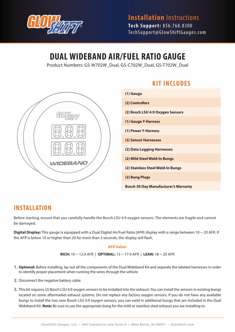
KIT INCLUDES
DUAL WIDEBAND AIR/FUEL RATIO GAUGEProduct Numbers: GS-W702W_Dual, GS-C702W_Dual, GS-T702W_Dual
(1) Gauge
(2) Controllers
(2) Bosch LSU 4.9 Oxygen Sensors
(1) Gauge Y-Harness
(1) Power Y-Harness
(2) Sensor Harnesses
(2) Data Logging Harnesses
(2) Mild Steel Weld-In Bungs
(2) Stainless Steel Weld-In Bungs
(2) Bung Plugs
Bosch 30 Day Manufacturer’s Warranty
INSTALLATIONBefore starting, ensure that you carefully handle the Bosch LSU 4.9 oxygen sensors. The elements are fragile and cannot be damaged.
Digital Display: This gauge is equipped with a Dual Digital Air/Fuel Ratio (AFR) display with a range between 10 ~ 20 AFR. If the AFR is below 10 or higher than 20 for more than 3 seconds, the display will flash.
AFR Value:
RICH: 10 ~ 12.9 AFR | OPTIMAL: 13 ~ 17.9 AFR | LEAN: 18 ~ 20 AFR
1. Optional: Before installing, lay out all the components of the Dual Wideband Kit and separate the labeled harnesses in order to identify proper placement when running the wires through the vehicle.
2. Disconnect the negative battery cable.
3. This kit requires (2) Bosch LSU 4.9 oxygen sensors to be installed into the exhaust. You can install the sensors in existing bungs located on some aftermarket exhaust systems. Do not replace any factory oxygen sensors. If you do not have any available bungs to install the two new Bosch LSU 4.9 oxygen sensors, you can weld in additional bungs that are included in the Dual Wideband Kit. Note: Be sure to use the appropriate bung for the mild or stainless steel exhaust you are installing to.
GlowShif t G auges, LLC • 444 Commerce Lane Suite A • West Ber l in , NJ 08091 • GlowShif t .com
DUAL WIDEBAND
5
4
6
7
8
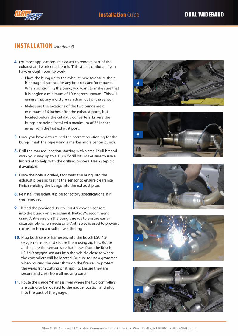
4. For most applications, it is easier to remove part of the exhaust and work on a bench. This step is optional if you have enough room to work.
• Place the bung up to the exhaust pipe to ensure there is enough clearance for any brackets and/or mounts. When positioning the bung, you want to make sure that it is angled a minimum of 10-degrees upward. This will ensure that any moisture can drain out of the sensor.
• Make sure the locations of the two bungs are a minimum of 6 inches after the exhaust ports, but located before the catalytic converters. Ensure the bungs are being installed a maximum of 36 inches away from the last exhaust port.
5. Once you have determined the correct positioning for the bungs, mark the pipe using a marker and a center punch.
6. Drill the marked location starting with a small drill bit and work your way up to a 15/16” drill bit. Make sure to use a lubricant to help with the drilling process. Use a step bit if available.
7. Once the hole is drilled, tack weld the bung into the exhaust pipe and test fit the sensor to ensure clearance. Finish welding the bungs into the exhaust pipe.
8. Reinstall the exhaust pipe to factory specifications, if it was removed.
9. Thread the provided Bosch LSU 4.9 oxygen sensors into the bungs on the exhaust. Note: We recommend using Anti-Seize on the bung threads to ensure easier disassembly, when necessary. Anti-Seize is used to prevent corrosion from a result of weathering.
10. Plug both sensor harnesses into the Bosch LSU 4.9 oxygen sensors and secure them using zip ties. Route and secure the sensor wire harnesses from the Bosch LSU 4.9 oxygen sensors into the vehicle close to where the controllers will be located. Be sure to use a grommet when routing the wires through the firewall to protect the wires from cutting or stripping. Ensure they are secure and clear from all moving parts.
11. Route the gauge Y-harness from where the two controllers are going to be located to the gauge location and plug into the back of the gauge.
INSTALLATION (continued)
GlowShif t G auges, LLC • 444 Commerce Lane Suite A • West Ber l in , NJ 08091 • GlowShif t .com
DUAL WIDEBAND
INSTALLATION (continued)
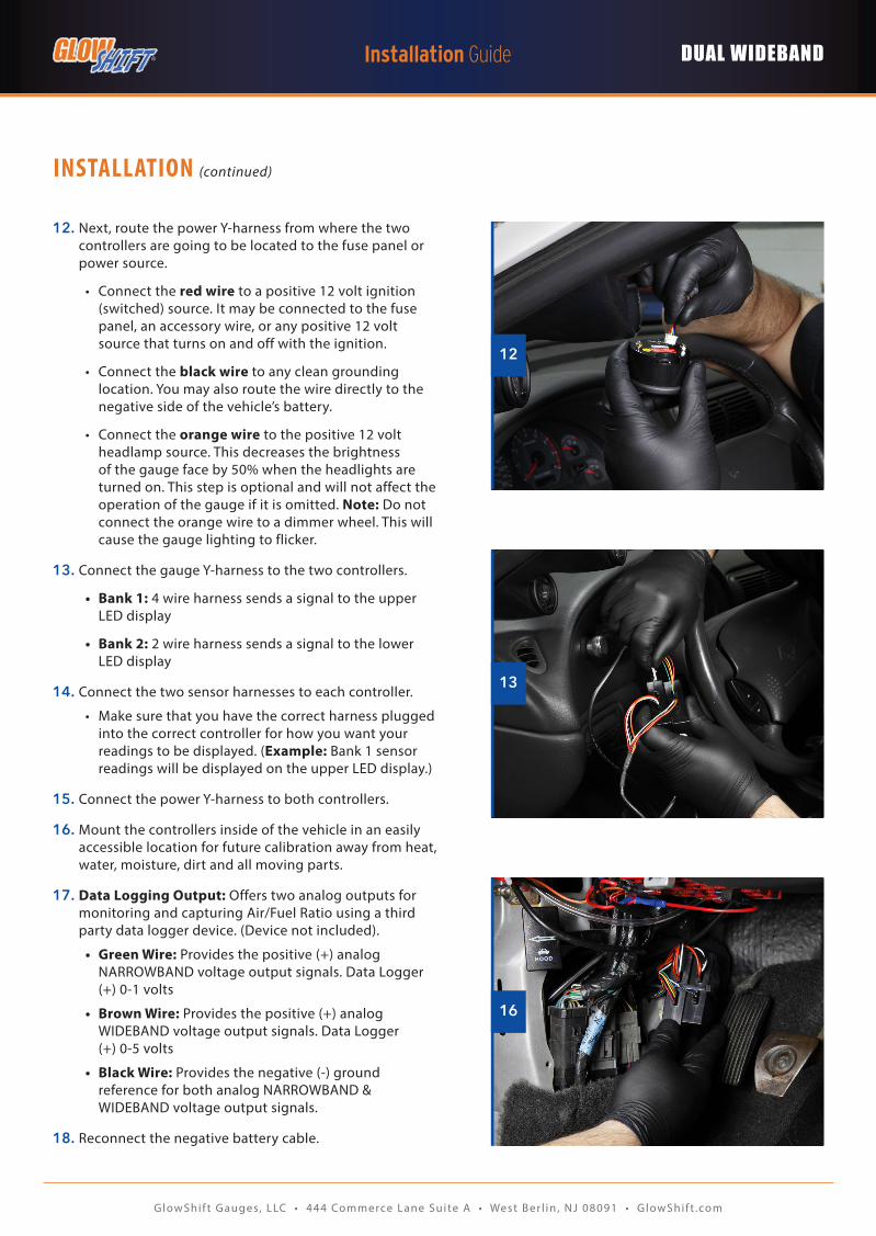
12. Next, route the power Y-harness from where the two controllers are going to be located to the fuse panel or power source.
• Connect the red wire to a positive 12 volt ignition (switched) source. It may be connected to the fuse panel, an accessory wire, or any positive 12 volt source that turns on and off with the ignition.
• Connect the black wire to any clean grounding location. You may also route the wire directly to the negative side of the vehicle’s battery.
• Connect the orange wire to the positive 12 volt headlamp source. This decreases the brightness of the gauge face by 50% when the headlights are turned on. This step is optional and will not affect the operation of the gauge if it is omitted. Note: Do not connect the orange wire to a dimmer wheel. This will cause the gauge lighting to flicker.
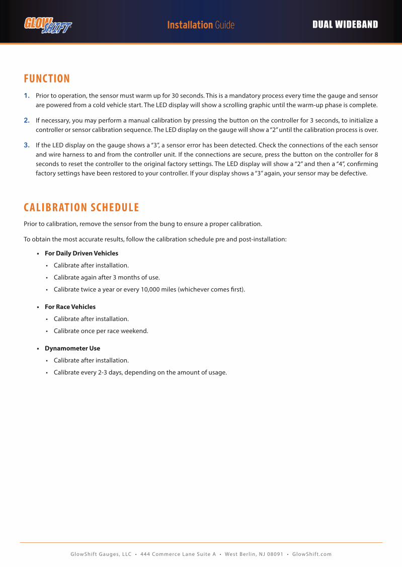
13. Connect the gauge Y-harness to the two controllers.
• Bank 1: 4 wire harness sends a signal to the upper LED display
• Bank 2: 2 wire harness sends a signal to the lower LED display
14. Connect the two sensor harnesses to each controller.
• Make sure that you have the correct harness plugged into the correct controller for how you want your readings to be displayed. (Example: Bank 1 sensor readings will be displayed on the upper LED display.)
15. Connect the power Y-harness to both controllers.
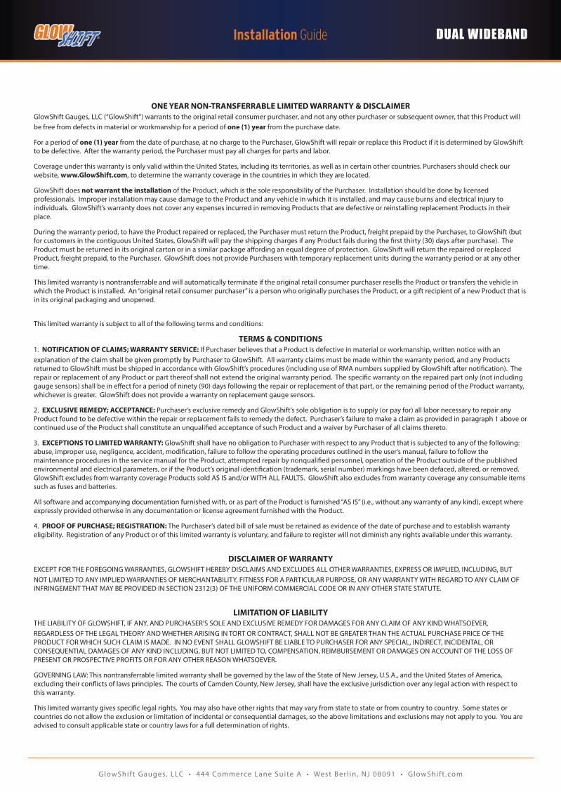
16. Mount the controllers inside of the vehicle in an easily accessible location for future calibration away from heat, water, moisture, dirt and all moving parts.
17. Data Logging Output: Offers two analog outputs for monitoring and capturing Air/Fuel Ratio using a third party data logger device. (Device not included).
• Green Wire: Provides the positive (+) analog NARROWBAND voltage output signals. Data Logger (+) 0-1 volts
• Brown Wire: Provides the positive (+) analog WIDEBAND voltage output signals. Data Logger (+) 0-5 volts
• Black Wire: Provides the negative (-) ground reference for both analog NARROWBAND & WIDEBAND voltage output signals.
18. Reconnect the negative battery cable.
13
12
16
GlowShif t G auges, LLC • 444 Commerce Lane Suite A • West Ber l in , NJ 08091 • GlowShif t .com
DUAL WIDEBAND
FUNCTION 1. Prior to operation, the sensor must warm up for 30 seconds. This is a mandatory process every time the gauge and sensor
are powered from a cold vehicle start. The LED display will show a scrolling graphic until the warm-up phase is complete.
2. If necessary, you may perform a manual calibration by pressing the button on the controller for 3 seconds, to initialize a controller or sensor calibration sequence. The LED display on the gauge will show a “2” until the calibration process is over.
3. If the LED display on the gauge shows a “3”, a sensor error has been detected. Check the connections of the each sensor and wire harness to and from the controller unit. If the connections are secure, press the button on the controller for 8 seconds to reset the controller to the original factory settings. The LED display will show a “2” and then a “4”, confirming factory settings have been restored to your controller. If your display shows a “3” again, your sensor may be defective.
C ALIBRATION SCHEDULEPrior to calibration, remove the sensor from the bung to ensure a proper calibration.
To obtain the most accurate results, follow the calibration schedule pre and post-installation:
• For Daily Driven Vehicles
• Calibrate after installation.
• Calibrate again after 3 months of use.
• Calibrate twice a year or every 10,000 miles (whichever comes first).
• For Race Vehicles
• Calibrate after installation.
• Calibrate once per race weekend.
• Dynamometer Use
• Calibrate after installation.
• Calibrate every 2-3 days, depending on the amount of usage.
GlowShif t G auges, LLC • 444 Commerce Lane Suite A • West Ber l in , NJ 08091 • GlowShif t .com
DUAL WIDEBAND
ONE YEAR NON-TRANSFERRABLE LIMITED WARRANTY & DISCLAIMERGlowShift Gauges, LLC (“GlowShift”) warrants to the original retail consumer purchaser, and not any other purchaser or subsequent owner, that this Product will be free from defects in material or workmanship for a period of one (1) year from the purchase date.
For a period of one (1) year from the date of purchase, at no charge to the Purchaser, GlowShift will repair or replace this Product if it is determined by GlowShift to be defective. After the warranty period, the Purchaser must pay all charges for parts and labor.
Coverage under this warranty is only valid within the United States, including its territories, as well as in certain other countries. Purchasers should check our website, www.GlowShift.com, to determine the warranty coverage in the countries in which they are located.
GlowShift does not warrant the installation of the Product, which is the sole responsibility of the Purchaser. Installation should be done by licensed professionals. Improper installation may cause damage to the Product and any vehicle in which it is installed, and may cause burns and electrical injury to individuals. GlowShift’s warranty does not cover any expenses incurred in removing Products that are defective or re installing replacement Products in their place.
During the warranty period, to have the Product repaired or replaced, the Purchaser must return the Product, freight prepaid by the Purchaser, to GlowShift (but for customers in the contiguous United States, GlowShift will pay the shipping charges if any Product fails during the first thirty (30) days after purchase). The Product must be returned in its original carton or in a similar package affording an equal degree of protection. GlowShift will return the repaired or replaced Product, freight prepaid, to the Purchaser. GlowShift does not provide Purchasers with temporary replacement units during the warranty period or at any other time.
This limited warranty is non transferrable and will automatically terminate if the original retail consumer purchaser resells the Product or transfers the vehicle in which the Product is installed. An “original retail consumer purchaser” is a person who originally purchases the Product, or a gift recipient of a new Product that is in its original packaging and unopened.
This limited warranty is subject to all of the following terms and conditions:
TERMS & CONDITIONS1. NOTIFICATION OF CLAIMS; WARRANTY SERVICE: If Purchaser believes that a Product is defective in material or workmanship, written notice with an explanation of the claim shall be given promptly by Purchaser to GlowShift. All warranty claims must be made within the warranty period, and any Products returned to GlowShift must be shipped in accordance with GlowShift’s procedures (including use of RMA numbers supplied by GlowShift after notification). The repair or replacement of any Product or part thereof shall not extend the original warranty period. The specific warranty on the repaired part only (not including gauge sensors) shall be in effect for a period of ninety (90) days following the repair or replacement of that part, or the remaining period of the Product warranty, whichever is greater. GlowShift does not provide a warranty on replacement gauge sensors.
2. EXCLUSIVE REMEDY; ACCEPTANCE: Purchaser’s exclusive remedy and GlowShift’s sole obligation is to supply (or pay for) all labor necessary to repair any Product found to be defective within the repair or replacement fails to remedy the defect. Purchaser’s failure to make a claim as provided in paragraph 1 above or continued use of the Product shall constitute an unqualified acceptance of such Product and a waiver by Purchaser of all claims thereto.
3. EXCEPTIONS TO LIMITED WARRANTY: GlowShift shall have no obligation to Purchaser with respect to any Product that is subjected to any of the following: abuse, improper use, negligence, accident, modification, failure to follow the operating procedures outlined in the user’s manual, failure to follow the maintenance procedures in the service manual for the Product, attempted repair by non qualified personnel, operation of the Product outside of the published environmental and electrical parameters, or if the Product’s original identification (trademark, serial number) markings have been defaced, altered, or removed. GlowShift excludes from warranty coverage Products sold AS IS and/or WITH ALL FAULTS. GlowShift also excludes from warranty coverage any consumable items such as fuses and batteries.
All software and accompanying documentation furnished with, or as part of the Product is furnished “AS IS” (i.e., without any warranty of any kind), except where expressly provided otherwise in any documentation or license agreement furnished with the Product.
4. PROOF OF PURCHASE; REGISTRATION: The Purchaser’s dated bill of sale must be retained as evidence of the date of purchase and to establish warranty eligibility. Registration of any Product or of this limited warranty is voluntary, and failure to register will not diminish any rights available under this warranty.
DISCLAIMER OF WARRANTYEXCEPT FOR THE FOREGOING WARRANTIES, GLOWSHIFT HEREBY DISCLAIMS AND EXCLUDES ALL OTHER WARRANTIES, EXPRESS OR IMPLIED, INCLUDING, BUT NOT LIMITED TO ANY IMPLIED WARRANTIES OF MERCHANTABILITY, FITNESS FOR A PARTICULAR PURPOSE, OR ANY WARRANTY WITH REGARD TO ANY CLAIM OF INFRINGEMENT THAT MAY BE PROVIDED IN SECTION 2 312(3) OF THE UNIFORM COMMERCIAL CODE OR IN ANY OTHER STATE STATUTE.
LIMITATION OF LIABILITYTHE LIABILITY OF GLOWSHIFT, IF ANY, AND PURCHASER’S SOLE AND EXCLUSIVE REMEDY FOR DAMAGES FOR ANY CLAIM OF ANY KIND WHATSOEVER, REGARDLESS OF THE LEGAL THEORY AND WHETHER ARISING IN TORT OR CONTRACT, SHALL NOT BE GREATER THAN THE ACTUAL PURCHASE PRICE OF THE PRODUCT FOR WHICH SUCH CLAIM IS MADE. IN NO EVENT SHALL GLOWSHIFT BE LIABLE TO PURCHASER FOR ANY SPECIAL, INDIRECT, INCIDENTAL, OR CONSEQUENTIAL DAMAGES OF ANY KIND INCLUDING, BUT NOT LIMITED TO, COMPENSATION, REIMBURSEMENT OR DAMAGES ON ACCOUNT OF THE LOSS OF PRESENT OR PROSPECTIVE PROFITS OR FOR ANY OTHER REASON WHATSOEVER.
GOVERNING LAW: This non transferrable limited warranty shall be governed by the law of the State of New Jersey, U.S.A., and the United States of America, excluding their conflicts of laws principles. The courts of Camden County, New Jersey, shall have the exclusive jurisdiction over any legal action with respect to this warranty.
This limited warranty gives specific legal rights. You may also have other rights that may vary from state to state or from country to country. Some states or countries do not allow the exclusion or limitation of incidental or consequential damages, so the above limitations and exclusions may not apply to you. You are advised to consult applicable state or country laws for a full determination of rights.