Embed Size (px)
DESCRIPTION
ducab connect
Citation preview
www.ducab.com
CABLE GLANDS
Technical Information
Industrial Glands
Fire Performance Cable Glands
Insulated Cable Glands
Hazardous Area Glands
North American Specification Connectors
Accessories

www.ducab.com
Application
The Ducab Connect range of Cable Connectors & Cable Glands for
Hazardous and Wet Locations are versatile enough to meet virtually all
situations where flexible and non flexible cables are used instead of pipe
conduit systems. Designed for both offshore and onshore requirements the
options available cover Armoured, Armored & Jacketed and Non-Armored
(e.g. IEEE45) Types and also Interlocked or Corrugated Continuously
Welded MC (or MC-HL), and Teck cables.
Solutions for virtually all-conceivable cables permitted for use in hazardous
locations when installed in both Class / Divisions and Class / Zones
classification concepts.
Products
Ducab Connect Hazardous Location Cable Connectors comply with
prevailing UL, ISA & ANSI Standards and meet the requirements of NEC
and CEC installation code requirements. In addition product compliance
with ABS and US Coast Guards USCG14CFR requirements is also offered.
Specifications & Approvals
Ducab North American SpecificationCable Connector Products
www.ducab.com
North American SpecificationCable Connector Products
Note: *LSF Shrouds also available on request. Marine approvals including Lloyds, DNV & ABS are also available from Ducab.
Technical DataType TMCXDesign Specification UL 514B, UL 886, UL 2225, UL 2279CSA Approval Certificate Number 1129339
Code of Protection Category Class I Div 1 & 2 Groups ABCD, Class II Div 1 & 2 Groups EFG, Class III Div 1& 2, Class I Zone 1 Ex d IIC, Enclosure Type 3, 4 and 4X
Compliance StandardsCAN/CSA-C22.2 Number 18-92, CSA C22.2 Number 25-1966, CSA C22.2Number 174-M1984, CAN/CSA-C22.2 Number 94-M91, CAN/CSA-E60079-0-2001, IEC 60079-0 1998, CAN/CSA E79-1-95, CAN/CSA-E79-7-95
UL Listing File Number CYMX7.E161256, CYMJ.E256366
Code of Protection Category Class I Div 1 & 2 Groups ABCD, Class II Div 1 & 2 Groups EFG, Class III Div 1& 2, Class I Zone 1 AEx d IIC, Ordinary & Wet Locations
Compliance Standards UL 514B, UL 886, UL 2225, UL 2227, ANSI/UL 60079-0, ANSI/UL 60079-1GOST R Certificate Number POCC GB. 05.B01912Code of Protection Category Ex d IIC U / Ex e II UCompliance Standards P 52350.0-2005, P 52350.1-2005, P 52350.7-2005GGTN Permit Number PPC 00-18262GOST K Certificate Number KZ7500052.05.01.00063RoK Permit for Use Number 08-067693Lloyds Approval Number 01/00172DNV Approval Number E-6157ABS Approval Number 01-LD 234401-PDAContinuous Operating Temperature -60°C to +130°CIngress Protection Rating IP66NEMA Rating NEMA 4X
Standard Cable Connector Material Copper Free Aluminum (<0.4%)Alternative Cable Connector Material Electroless Nickel Plated Brass, Stainless SteelSeal Material LSF Thermoplastic Elastomer / Epoxy Resin Barrier Compound
Cable Type Corrugated & Interlocked Metal Clad Armor (MC) or TECK, ContinuouslyWelded Metal Clad Armor (MCHL)
Armour Clamping Earth Continuity in Contact With Metal Clad ArmourSealing Technique Displacement SealSealing Area(s) Inner Compound Barrier & Cable Outer Jacket
Optional Accessories Locknut, Shroud, Entry Thread Seal, Serrated Washer, Earth Tag,Adaptor/Reducer
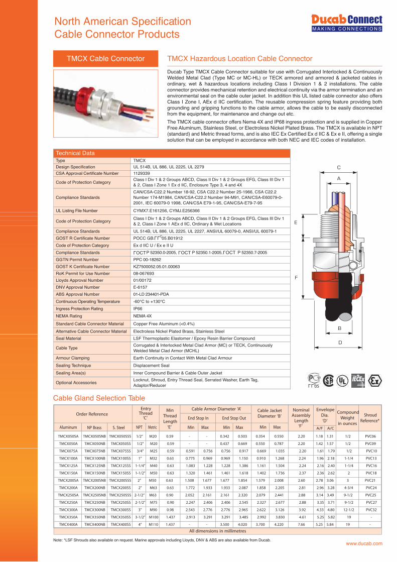
TMCX Hazardous Location Cable ConnectorTMCX Cable Connector
A
C
E
F
B
D
TMCX050SA TMCX050SNB TMCX050SSS 1/2” M20 0.59 - - 0.342 0.503 0.354 0.550 2.20 1.18 1.31 1/2 PVC06
TMCX050A TMCX050NB TMCX050SS 1/2” M20 0.59 - - 0.437 0.669 0.550 0.787 2.20 1.42 1.57 1/2 PVC09
TMCX075A TMCX075NB TMCX075SS 3/4” M25 0.59 0.591 0.756 0.756 0.917 0.669 1.035 2.20 1.61 1.79 1/2 PVC10
TMCX100A TMCX100NB TMCX100SS 1” M32 0.63 0.775 0.969 0.969 1.150 0.910 1.268 2.24 1.96 2.18 1-1/4 PVC13
TMCX125A TMCX125NB TMCX125SS 1-1/4” M40 0.63 1.083 1.228 1.228 1.386 1.161 1.504 2.24 2.16 2.40 1-1/4 PVC16
TMCX150A TMCX150NB TMCX150SS 1-1/2” M50 0.63 1.320 1.461 1.461 1.618 1.402 1.736 2.37 2.36 2.62 2 PVC18
TMCX200SA TMCX200SNB TMCX200SSS 2” M50 0.63 1.508 1.677 1.677 1.854 1.579 2.008 2.60 2.78 3.06 3 PVC21
TMCX200A TMCX200NB TMCX200SS 2” M63 0.63 1.772 1.933 1.933 2.087 1.858 2.205 2.81 2.96 3.28 4-3/4 PVC24
TMCX250SA TMCX250SNB TMCX250SSS 2-1/2” M63 0.90 2.052 2.161 2.161 2.320 2.079 2.441 2.88 3.14 3.49 9-1/2 PVC25
TMCX250A TMCX250NB TMCX250SS 2-1/2” M75 0.90 2.247 2.406 2.406 2.545 2.327 2.677 2.88 3.35 3.71 9-1/2 PVC27
TMCX300A TMCX300NB TMCX300SS 3” M90 0.98 2.543 2.776 2.776 2.965 2.622 3.126 3.92 4.33 4.80 12-1/2 PVC32
TMCX350A TMCX350NB TMCX350SS 3-1/2” M100 1.437 2.913 3.291 3.291 3.485 2.992 3.830 4.61 5.25 5.82 19 -
TMCX400A TMCX400NB TMCX400SS 4” M110 1.437 - - 3.500 4.020 3.700 4.220 7.66 5.25 5.84 19 -
Order ReferenceEntryThread‘C’
Min
Thread
Length
‘E’
NominalAssemblyLength‘F’
Envelope
Dia.
‘D’
Compound
Weight
in ounces
Shroud
Reference*
Cable Armor Diameter ‘A’ Cable Jacket
Diameter ‘B’
Aluminum NP Brass S. Steel NPT Metric Min MaxMin Max Min Max
End Stop OutEnd Stop In
A/F A/C
LLU05
LLU
OCTL
OCTL
OCTL
All dimensions in millimetres
Cable Gland Selection Table
Ducab Type TMCX Cable Connector suitable for use with Corrugated Interlocked & Continuously Welded Metal Clad (Type MC or MC-HL) or TECK armored and armored & jacketed cables in ordinary, wet & hazardous locations including Class I Division 1 & 2 installations. The cable connector provides mechanical retention and electrical continuity via the armor termination and an environmental seal on the cable outer jacket. In addition this UL listed cable connector also offers Class I Zone I, AEx d IIC certification. The reusable compression spring feature providing both grounding and gripping functions to the cable armor, allows the cable to be easily disconnected from the equipment, for maintenance and change out etc.The TMCX cable connector offers Nema 4X and IP68 ingress protection and is supplied in Copper Free Aluminum, Stainless Steel, or Electroless Nickel Plated Brass. The TMCX is available in NPT (standard) and Metric thread forms, and is also IEC Ex Certified Ex d IIC & Ex e II, offering a single solution that can be employed in accordance with both NEC and IEC codes of installation.
North American SpecificationCable Connector Products
Note: *LSF Shrouds also available on request. Marine approvals including Lloyds, DNV & ABS are also available from Ducab.
Technical DataType TMCDesign Specification UL 514B, UL 886CSA Approval Certificate Number 1129339
Code of Protection Category Class II Div 1 & 2 Groups EFG, Class III Div 1 & 2, Class I Zone 1 Ex e II,Enclosure Type 3, 4 and 4X
Compliance StandardsCAN/CSA-C22.2 Number 18-92, CSA C22.2 Number 25-1966, CSA C22.2Number 174-M1984, CAN/CSA-C22.2 Number 94-M91, CAN/CSA-E60079-0-2001, IEC 60079-0 1998, CAN/CSA-E79-7-95
UL Listing File Number PJOX.E163112, CYMJ.E256366
Code of Protection Category Class II Div 1 & 2 Groups EFG, Class III Div 1 & 2, Class I Zone 1 AEx e II,Ordinary & Wet Locations
Compliance Standards UL 514B, UL 886, ANSI/UL 60079-0, ANSI/UL 60079-7
GOST R Certificate Number POCC GB. 05.B01912
Code of Protection Category Ex e IICompliance Standards P 52350.0-2005, P 52350.7-2005GGTN Permit Number PPC 00-18262GOST K Certificate Number KZ7500052.05.01.00063RoK Permit for Use Number 08-067693Lloyds Approval Number 01/00172
DNV Approval Number E-6157
ABS Approval Number 01-LD 234401-PDA
Continuous Operating Temperature -60°C to +130°C
Ingress Protection Rating IP66
NEMA Rating NEMA 4XStandard Cable Connector Material Copper Free Aluminum (<0.4%)Alternative Cable Connector Material Electroless Nickel Plated Brass, Stainless SteelSeal Material LSF Thermoplastic Elastomer
Cable Type Corrugated & Interlocked Metal Clad Armor (MC) or TECK, ContinuouslyWelded Metal Clad Armor (MCHL)
Armour Clamping Earth Continuity in Contact With Metal Clad Armour
Sealing Technique Displacement Seal
Sealing Area(s) Cable Outer JacketOptional Accessories Locknut, Shroud, Entry Thread Seal, Serrated Washer, Earth Tag, Adaptor/Reducer
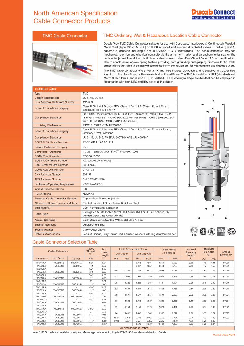
TMC Ordinary, Wet & Hazardous Location Cable Connector
A
C
E
F
D
B
Order ReferenceEntryThread‘C’
MinThreadLength‘E’
NominalAssemblyLength‘F’
EnvelopeDiameter
‘D’Shroud
Reference*
Cable Armor Diameter ‘A’ Cable JacketDiameter ‘B’
Aluminum NP Brass S. Steel NPT Min MaxMin Max Min Max
End Stop OutEnd Stop In
TMC050SA TMC050SNB TMC050SSS 1/2” 0.59 - - 0.342 0.503 0.354 0.550 2.20 1.18 1.31 PVC06TMC050A TMC050NB TMC050SS 1/2” 0.59 - - 0.437 0.669 0.510 0.787 2.20 1.42 1.57 PVC09
TMC050LA - - 1/2” 0.590.591 0.756 0.756 0.917 0.669 1.035 2.20 1.61 1.79 PVC10
TMC075A TMC075NB TMC075SS 3/4” 0.59TMC075LA - - 3/4” 0.63
0.775 0.969 0.969 1.150 0.910 1.268 2.24 1.96 2.18 PVC13TMC100A TMC100NB TMC100SS 1” 0.63
TMC100LA - - 1” 0.631.083 1.228 1.228 1.386 1.161 1.504 2.24 2.16 2.40 PVC16
TMC125A TMC125NB TMC125SS 1-1/4” 0.63TMC125LA - - 1-1/4” 0.63
1.320 1.461 1.461 1.618 1.402 1.736 2.37 2.36 2.62 PVC18TMC150A TMC150NB TMC150SS 1-1/2” 0.63
TMC150LA - - 1-1/2” 0.631.508 1.677 1.677 1.854 1.579 2.008 2.58 2.78 3.06 PVC21
TMC200SA TMC200SNB TMC200SSS 2” 0.63TMC150XLA - - 1-1/2” 0.63
1.772 1.933 1.933 2.087 1.858 2.205 2.49 2.96 3.28 PVC24TMC200A TMC200NB TMC200SS 2” 0.63
TMC200LA - - 2” 0.902.052 2.161 2.161 2.320 2.079 2.441 2.50 3.14 3.49 PVC25
TMC250SA TMC250SNB TMC250SSS 2-1/2” 0.90TMC200XLA - - 2” 0.90
2.247 2.406 2.406 2.545 2.327 2.677 2.52 3.35 3.71 PVC27TMC250A TMC250NB TMC250SS 2-1/2” 0.90TMC300A TMC300NB TMC300SS 3” 0.98 2.543 2.776 2.776 2.965 2.622 3.126 3.57 4.33 4.80 PVC32TMC350A TMC350NB TMC350SS 3-1/2” 1.437 2.913 3.291 3.291 3.485 2.992 3.830 4.61 5.25 5.82 -TMC400A TMC400NB TMC400SS 4” 1.437 - - 3.500 4.020 3.700 4.220 7.66 5.28 5.84 -
A/F A/C
LLU 05
LLU
OCTL
OCTL
All dimensions in inches
TMC Cable Connector
Cable Connector Selection Table
Ducab Type TMC Cable Connector suitable for use with Corrugated Interlocked & Continuously Welded Metal Clad (Type MC or MC-HL) or TECK armored and armored & jacketed cables in ordinary, wet & hazardous locations including Class II Division 1 & 2 installations. The cable connector provides mechanical retention and electrical continuity via the armor termination and an environmental seal on the cable outer jacket. In addition this UL listed cable connector also offers Class I Zone I, AEx e II certification. The re-usable compression spring feature providing both grounding and gripping functions to the cable armor, allows the cable to be easily disconnected from the equipment, for maintenance and change out etc.The TMC cable connector offers Nema 4X and IP68 ingress protection and is supplied in Copper free Aluminum, Stainless Steel, or Electroless Nickel Plated Brass. The TMC is available in NPT (standard) and Metric thread forms, and is also IEC Ex Certified Ex e II, offering a single solution that can be employed in accordance with both NEC and IEC codes of installation.
www.ducab.com
www.ducab.com
CABLE GLANDS
Technical Information
Industrial Glands
Fire Performance Cable Glands
Insulated Cable Glands
Hazardous Area Glands
North American Specification Connectors
Accessories

Thread Conversion Adaptors and Reducers
www.ducab.com
The Ducab Connect range of Thread Conversion Adaptors, Reducers and
associated products are available for use in Industrial, Marine and
Hazardous Area applications, and are particularly suited to construction
projects where a high volume of cables of all types and sizes are being
installed. When the cable gland fits the cable but its connecting thread
differs from that of the equipment the best solution may be to use a Ducab
thread conversion adaptor, especially when schedules are critical and time
is of the essence. Ducab thread conversion adaptors and reducers offer the
flexibility of allowing the job to progress by using a standard off the shelf
product to save time and ultimate cost compared with modifying hole sizes
in equipment.
In addition to Thread Conversion Adaptors and Reducers, Ducab Products
also provides, Unions, Stopper Plugs, Breather / Drain Plugs and Insulated
Adaptors. All products in this range are available in a variety of materials,
both metallic and non-metallic, and can be supplied in a combination of
different thread forms and sizes including Metric, PG, NPT, BSP etc.
Products
Ducab Connect Industrial, Marine and Hazardous Area Thread Conversion
Adaptors, Reducers, Stopper Plugs and Breather Drain Plugs comply with
the latest IEC standards and are offered with certification from a host of
internationally recognised bodies. This range of certification includes ATEX,
IEC Ex, CSA, UL, GOST R. GOST K and more.
Specifications & Approvals
Application
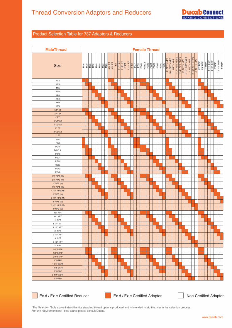
Thread Conversion Adaptors and Reducers
Product Selection Table for 737 Adaptors & Reducers
Size M16
M20
M25
M32
M40
M50
M63
M75
5/8"
ET3/
4"ET
1"ET
11/
4"ET
11/
2"ET
2"ET
21/
2"ET
3"ET
PG7
PG9
PG11
PG13
.5PG
16PG
21PG
29PG
36PG
42PG
481/
2"N
PT/N
PS3/
4"N
PT/N
PS1"
NPT
/NPS
11/
4"N
PT/N
PS1
1/2"
NPT
/NPS
2"N
PT/N
PS2
1/2"
NPT
/NPS
3"N
PT/N
PS3
1/2"
NPT
/NPS
4"N
PT/N
PS1/
2"BS
P3/
4"BS
P1"
BSP
11/
4"BS
P1
1/2"
BSP
2"BS
P2
1/2"
BSP
3"BS
P
M16M20M25M32M40M50M63M75
5/8" ET3/4" ET1" ET
1 1/4" ET1 1/2" ET
2" ET2 1/2" ET
3" ET
PG7PG9PG11
PG13.5PG16PG21PG29PG36PG42PG48
1/2" NPS (M)3/4" NPS (M)1" NPS (M)
11/4" NPS (M)1 1/2" NPS (M)
2" NPS (M)2 1/2" NPS (M)
3" NPS (M)3 1/2" NPS (M)
4" NPS (M)
1/2" NPT3/4" NPT1" NPT
1 1/4" NPT1 1/2" NPT
2" NPT2 1/2" NPT
3" NPT3 1/2" NPT
4" NPT
1/2" BSPP5/8" BSPP3/4" BSPP1" BSPP
1 1/4" BSPP1 1/2" BSPP
2" BSPP2 1/2" BSPP
3" BSPP
MALE THREAD FEMALE THREADMaleThread Female Thread
*The Selection Table above indentifies the standard thread options produced and is intended to aid the user in the selection process.For any requirements not listed above please consult Ducab.
Ex d / Ex e Certified Reducer Ex d / Ex e Certified Adaptor Non-Certified Adaptor
www.ducab.com
Thread Conversion Adaptors and Reducers
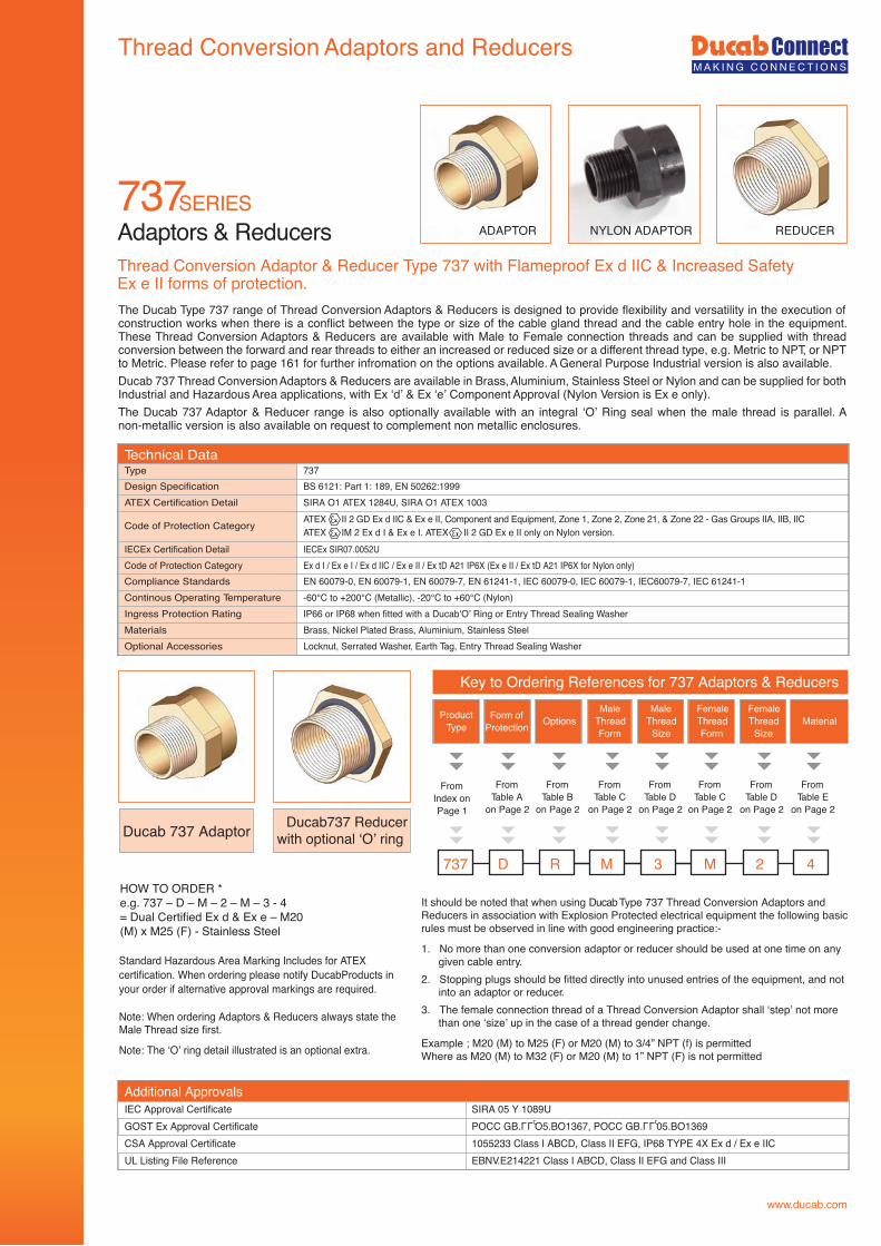
737SERIESAdaptors & Reducers
HOW TO ORDER *e.g. 737 – D – M – 2 – M – 3 - 4= Dual Certified Ex d & Ex e – M20(M) x M25 (F) - Stainless Steel.
It should be noted that when using Ducab Type 737 Thread Conversion Adaptors andReducers in association with Explosion Protected electrical equipment the following basicrules must be observed in line with good engineering practice:-
1. No more than one conversion adaptor or reducer should be used at one time on anygiven cable entry.
2. Stopping plugs should be fitted directly into unused entries of the equipment, and notinto an adaptor or reducer.
3. The female connection thread of a Thread Conversion Adaptor shall ‘step’ not morethan one ‘size’ up in the case of a thread gender change.
Example ; M20 (M) to M25 (F) or M20 (M) to 3/4” NPT (f) is permittedWhere as M20 (M) to M32 (F) or M20 (M) to 1” NPT (F) is not permitted
Thread Conversion Adaptor & Reducer Type 737 with Flameproof Ex d IIC & Increased SafetyEx e II forms of protection.
Standard Hazardous Area Marking Includes for ATEXcertification. When ordering please notify DucabProducts inyour order if alternative approval markings are required.
Note: When ordering Adaptors & Reducers always state theMale Thread size first.
Note: The ‘O’ ring detail illustrated is an optional extra.
Ducab 737 Adaptor Ducab737 Reducerwith optional ‘O’ ring
FromIndex onPage 1
FromTable A
on Page 2
FromTable B
on Page 2
FromTable C
on Page 2
FromTable D
on Page 2
FromTable C
on Page 2
737 D R M 3 M
ProductType
Form ofProtection Options
MaleThreadForm
MaleThread
Size
FemaleThreadForm
Key to Ordering References for 737 Adaptors & Reducers
FromTable D
on Page 2
FromTable E
on Page 2
2 4
FemaleThread
SizeMaterial
ADAPTOR NYLON ADAPTOR REDUCER
Additional ApprovalsIEC Approval Certificate SIRA 05 Y 1089UGOST Ex Approval Certificate POCC GB. O5.BO1367, POCC GB. 05.BO1369CSA Approval Certificate 1055233 Class I ABCD, Class II EFG, IP68 TYPE 4X Ex d / Ex e IICUL Listing File Reference EBNV.E214221 Class I ABCD, Class II EFG and Class III
LLU LLU
The Ducab Type 737 range of Thread Conversion Adaptors & Reducers is designed to provide flexibility and versatility in the execution of construction works when there is a conflict between the type or size of the cable gland thread and the cable entry hole in the equipment. These Thread Conversion Adaptors & Reducers are available with Male to Female connection threads and can be supplied with thread conversion between the forward and rear threads to either an increased or reduced size or a different thread type, e.g. Metric to NPT, or NPT to Metric. Please refer to page 161 for further infromation on the options available. A General Purpose Industrial version is also available.Ducab 737 Thread Conversion Adaptors & Reducers are available in Brass, Aluminium, Stainless Steel or Nylon and can be supplied for both Industrial and Hazardous Area applications, with Ex ‘d’ & Ex ‘e’ Component Approval (Nylon Version is Ex e only).The Ducab 737 Adaptor & Reducer range is also optionally available with an integral ‘O’ Ring seal when the male thread is parallel. A non-metallic version is also available on request to complement non metallic enclosures.
Technical Data737
Design Specification BS 6121: Part 1: 189, EN 50262:1999ATEX Certification Detail SIRA O1 ATEX 1284U, SIRA O1 ATEX 1003
Code of Protection Category ATEX II 2 GD Ex d IIC & Ex e II, Component and Equipment, Zone 1, Zone 2, Zone 21, & Zone 22 - Gas Groups IIA, IIB, IICATEX IM 2 Ex d I & Ex e I. ATEX II 2 GD Ex e II only on Nylon version.
IECEx Certification Detail IECEx SIR07.0052UCode of Protection Category Ex d I / Ex e I / Ex d IIC / Ex e II / Ex tD A21 IP6X (Ex e II / Ex tD A21 IP6X for Nylon only)Compliance Standards EN 60079-0, EN 60079-1, EN 60079-7, EN 61241-1, IEC 60079-0, IEC 60079-1, IEC60079-7, IEC 61241-1Continous Operating Temperature -60°C to +200°C (Metallic), -20°C to +60°C (Nylon)Ingress Protection Rating IP66 or IP68 when fitted with a Ducab‘O’ Ring or Entry Thread Sealing WasherMaterials Brass, Nickel Plated Brass, Aluminium, Stainless SteelOptional Accessories Locknut, Serrated Washer, Earth Tag, Entry Thread Sealing Washer
Type
www.ducab.com
D
E
C
G
B
A
C
E
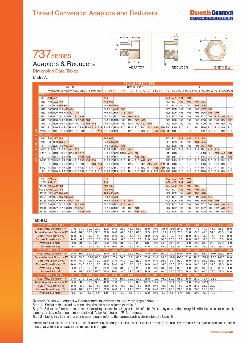
Adaptors & Reducers
Table ADimension Data Tables
A01 A02 A03 A04 A05 A06 A07 A08 A09 A10 A11 A12 A13 A14 A15 A16 A17 A18 A19 A2024.0 24.0 30.0 30.0 33.0 36.0 36.0 46.0 55.0 60.0 70.0 100.0 110.0 24.0 46.0 41.0 41.0 46.0 55.0 55.026.6 26.6 33.3 33.3 36.6 40.0 40.0 51.0 61.0 66.5 77.6 110.0 122.0 26.6 51.0 43.5 46.0 51.0 61.0 61.015.0 15.0 15.0 15.0 15.0 15.0 15.0 15.0 15.0 15.0 15.0 15.0 19.0 15.0 15.0 15.0 15.0 15.0 15.0 15.016.0 16.0 16.0 16.0 16.0 16.0 16.0 16.0 16.0 21.0 16.0 20.0 20.0 16.0 16.0 16.0 16.0 16.0 15.0 16.020.0 20.0 20.0 20.0 20.0 20.0 20.0 20.0 20.0 6.0 20.0 24.0 24.0 20.0 20.0 20.0 20.0 20.0 27.0 20.08.0 13.5 13.5 19.0 20.0 20.0 26.0 29.0 32.0 42.0 42.0 65.0 79.3 9.7 20.0 20.0 26.0 32.0 29.0 42.0A21 A22 A23 A24 A25 A26 A27 A28 A29 A30 A31 A32 A33 A34 A35 A36 A37 A38 A39 A4065.0 80.0 95.0 70.0 95.0 123.0 27.0 55.0 60.0 70.0 80.0 80.0 100.0 114.0 46.0 65.0 95.0 110.0 127.0 36.072.0 89.0 105.0 80.0 105.0 138.0 30.0 6.0 66.5 77.6 89.0 89.0 110.0 132.0 51.0 72.0 105.0 122.0 146.0 40.015.0 15.0 15.0 15.0 25.0 25.0 15.0 16.0 25.0 16.0 16.0 23.0 5.0 36.0 16.0 16.0 23.0 25.0 36.0 15.016.0 23.0 25.0 16.0 25.0 25.0 16.0 16.0 17.0 16.0 16.0 16.0 20.0 22.0 16.0 16.0 25.0 27.0 36.0 16.020.0 27.0 30.0 20.0 30.0 35.0 20.0 20.0 20.0 20.0 20.0 20.0 24.0 38.0 20.0 20.0 30.0 32.0 39.0 20.042.0 55.0 65.0 55.0 75.0 80.0 14.0 38.0 38.0 38.0 49.0 60.0 75.0 75.0 26.3 38.0 60.0 75.0 75.0 14.0R01 R02 R03 R04 R05 R06 R07 R08 R09 R10 R11 R12 R13 R14 R15 R16 R17 R18 - -24.0 27.0 30.0 33.0 36.0 46.0 55.0 70.0 80.0 95.0 110.0 46.0 50.0 65.0 80.0 95.0 110.0 123.0 - -26.6 30.0 33.3 36.6 40.0 51.0 61.0 77.6 89.0 105.0 122.0 51.0 55.4 72.1 88.6 105.0 122.0 138.0 - -15.0 15.0 15.0 15.0 15.0 15.0 15.0 15.0 15.0 15.0 19.0 16.0 16.0 16.0 23.0 25.0 25.0 29.0 - -20.0 20.0 20.0 20.0 20.0 20.0 21.0 21.0 25.0 25.0 29.0 22.0 22.0 22.0 29.0 35.0 35.0 39.0 - -5.0 5.0 5.0 5.0 5.0 5.0 6.0 6.0 10.0 10.0 10.0 6.0 6.0 6.0 6.0 10.0 10.0 10.0 - -
To obtain Ducab 737 Adaptor & Reducer nominal dimensions, follow the steps below:-Step 1 - Select male thread by consulting the left hand column of table ‘A’Step 2 - Select the female thread size by consulting column headings at the top of table ‘A’, and by cross referencing this with the selection in step 1,identify the key reference number prefixed ‘A’ for Adaptor and ‘R’ for reducer.Step 3 - Using this key reference number, please refer to the corresponding dimensions in Table ‘B’.
Please note that the data in tables ‘A’ and ‘B’ above include Adaptors and Reducers which are certified for use in Hazardous Areas. Dimension data for otherIndustrial versions is available from Ducab on request.
ADAPTOR END VIEWREDUCER
737SERIES
Thread Conversion Adaptors and Reducers
www.ducab.com
FEMALE THREAD SIZEMETRIC NPT & BSPP PG
MI6 M20 M25 M32 M40 M50 M63 M75 M90 M100 1/2” 3/4” 1” 1-1/4” 1-1/2” 2” 2-1/2” 3” 3-1/2” 4” PG7 PG9 PG11 PG13.5 PG16 PG21 PG29 PG36 PG42 PG48METRIC
M16 A01 A01 A14 A01 A01 A01 A01M20 R01 A02 A03 A02 A03 R01 R01 A02 A02 A04 A03M25 R03 R03 A04 A06 R03 A04 A16 R03 R03 R03 R03 A04 A04M32 R05 R05 R05 A06 A08 R05 RO5 A17 A08 R05 R05 R07 R05 R05 A07 A35M40 R06 R06 R06 R06 A08 A09 R06 R07 R06 A18 A09 R06 R06 R06 R06 R06 R06 A08 A09M50 R07 R07 R07 R07 R07 A10 A11 R07 R08 R07 R07 A20 A21 R07 R07 R07 R07 R07 R07 R07 A10 A10 A11M63 R08 R08 R08 R08 R08 R08 A11 A31 R08 R08 R08 R08 R08 A24 A22 R08 R08 R08 R08 R08 R08 R08 R08 R08 A24M75 R10 R09 R09 R09 R09 R09 R09 A31 A12 R09 R09 R09 R09 R09 R09 A22 A23 R09 R09 R09 R09 R09 R09 R09 R09 R09 R09M90 R10 R10 R10 R10 R10 R10 R10 R092 A12 A13 R10 R10 R10 R10 R10 R10 R10 A24 A25 A26 R10 R10 R10 R10 R2 R10 R10 R10 R10 R10M100 R11 R11 R11 R11 R11 R11 R11 R11 R11 A13 R11 R11 R11 R11 R11 R11 R11 R11 A25 A26 R11 R11 R11 R11 R11 R11 R11 R11 R11 R11
NPT & BSPP1/2” R01 A27 A03 A02 A03 R01 R01 A27 A27 A27 A043/4” R03 R03 A04 A16 R03 A04 A16 R03 R03 R03 R03 A04 A041” R12 R05 R05 A07 A35 R05 R05 A07 A35 R05 R05 R05 R05 R05 A07 A35
1-1/4” R13 R12 R12 R12 A18 A28 R12 R12 R12 A35 A09 R12 R12 R12 R12 R12 R12 A18 A281-1/2” R13 R13 R13 R13 R13 A28 A31 R13 R13 R13 R139 A09 A36 R13 R13 R13 R13 R13 R13 R13 A28 A29 A31
2” R14 R14 R14 R14 R14 R14 A11 A31 R14 R14 R14 R14 R14 A36 A31 R14 R14 R14 R14 R14 R14 R14 R14 R14 A312-1/2” R15 R15 R15 R15 R15 R15 R15 A32 A33 R15 R15 R15 R15 R15 R15 A32 A37 R15 R15 R15 R15 R15 R15 R15 R15 R15 R15
3” R16 R16 R16 R16 R16 R16 R16 R16 A33 A34 R16 R16 R16 R16 R16 R16 R16 A25 A38 A39 R16 R16 R16 R16 R16 R16 R16 R16 R16 R163-1/2” R17 R17 R17 R17 R17 R17 R17 R17 R17 A34 R17 R17 R17 R17 R17 R17 R17 R17 A38 A39 R17 R17 R17 R17 R17 R17 R17 R17 R17 R17
4” R18 R18 R18 R18 R18 R18 R18 R18 R18 R18 R18 R18 R18 R18 R18 R18 R18 R18 R18 A39 R18 R18 R18 R18 R18 R18 R18 R18 R18 R18PG
PG7 A01 A01 A14 A02 A02 A01 A01PG9 A01 A01 A14 A02 A02 A01 A01PG11 A02 A02 A03 A02 A03 A02 A02 A02 A02 A02
PG13.5 A02 A02 A03 A02 A03 R01 R01 A02 A02 A03 A03PG16 R03 A27 A04 A06 A03 A03 A16 R02 R02 R02 A03 A03 A40PG21 R04 R04 A05 A06 A08 R04 A15 A16 R04 R04 R04 R04 R04 A05 A10PG29 R06 R06 R06 R06 A08 A09 R06 R06 A18 A18 A19 R06 R06 R06 R06 R06 R06 A08 A09PG36 R07 R07 R07 R07 R07 A28 A11 R07 R07 R07 A19 A19 R07 R07 R07 R07 R07 R07 R07 A09 A10 A11PG42 R07 R07 R07 R08 R08 A10 A24 R07 R07 R07 R07 R07 A21 R07 R07 R07 R07 R07 R07 R07 R07 A10 A11PG48 R08 R14 R14 R08 R14 R14 A11 A31 R08 R08 R08 R08 R08 A21 A22 R08 R08 R08 R08 R08 R08 R08 R08 R08 A11
MA
LET
HR
EA
DS
IZE
Table B737 ADAPTOR DETAIL
Across Flats Dimension ‘A’Across Corners Diameter ‘B’
Male Thread Length ‘C’Female Thread Length ‘D’
Protrusion Length ‘F’Nominal Bore ‘G’
737 ADAPTOR DETAILAcross Flats Dimension ‘A’
Across Corners Diameter ‘B’Male Thread Length ‘C’
Female Thread Length ‘D’Protrusion Length ‘F’
Nominal Bore ‘G’737 REDUCER DETAIL
Across Flats Dimension ‘A’Across Corners Diameter ‘B’
Male Thread Length ‘C’Female Thread Length ‘E’
Protrusion Length ‘F’
Thread Conversion Adaptors and Reducers
www.ducab.com
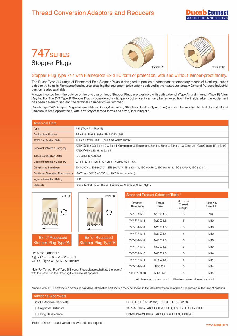
The Ducab Type 747 range of Flameproof Ex d Stopper Plugs is designed to provide a permanent or temporary means of blanking unused cable entry holes in Flameproof enclosures enabling the equipment to be safely deployed in the hazardous area. A General Purpose Industrial version is also available.Always inserted from the outside of the enclosure, these Stopper Plugs are available with both external (Type A) and internal (Type B) Allen Key facility. The 747 Type B Stopper Plug is considered as tamper-proof since it can only be removed from the inside, after the equipment has been de-energised and the terminal chamber cover removed.Ducab Type 747 Stopper Plugs are available in Brass, Aluminium, Stainless Steel or Nylon (Exe) and can be supplied for both Industrial and Hazardous Area applications, with a variety of thread forms and sizes, including NPT.
Stopper Plugs
Stopper Plug Type 747 with Flameproof Ex d IIC form of protection, with and without Tamper-proof facility.
Technical DataType 747 (Type A & Type B)
Design Specification BS 6121: Part 1: 1989, EN 50262:1999
ATEX Certification Detail SIRA 01 ATEX 1284U, SIRA 02 ATEX 1003X
Code of Protection CategoryATEX II 2 GD Ex d IIC & Ex e II Component & Equipment, Zone 1, Zone 2, Zone 21, & Zone 22 - Gas Groups IIA, IIB, IICATEX IM 2 Ex d I & Ex e I
IECEx Certification Detail IECEx SIR07.0056U
Code of Protection Category Ex d I / Ex e I / Ex d IIC / Ex e II / Ex tD A21 IP6X
Compliance Standards EN 60079-0, EN 60079-1, EN 60079-7, EN 61241-1, IEC 60079-0, IEC 60079-1, IEC 60079-7, IEC 61241-1
-60ºC to + 200ºC (-20ºC to +60ºC Nylon version)
Ingress Protection Rating IP66
Materials Brass, Nickel Plated Brass, Aluminium, Stainless Steel, Nylon
Additional ApprovalsGost Ex Approval Certificate POCC GB. 05.B01367, POCC GB. 05.B01369
CSA Approval Certificate 1055233 Class I ABCD, Class II EFG, IP68 TYPE 4X Ex d IIC
UL Listing file reference EBNV.E214221 Class I ABCD, Class II EFG, & Class III
Marked with ATEX certification details as standard. Alternative certification marking shown in the table below can be applied if requested at the time of ordering.
Note* : Other Thread Variations available on request.
Standard Product Selection Table *
OrderingReference
ThreadSize
MinimumThreadLength
Allen KeySize A/F
747-F-A-M-1 M16 X 1.5 15 M8
747-F-A-M-2 M20 X 1.5 15 M10
747-F-A-M-3 M25 X 1.5 15 M10
747-F-A-M-4 M32 X 1.5 15 M10
747-F-A-M-5 M40 X 1.5 15 M10
747-F-A-M-6 M50 X 1.5 15 M10
747-F-A-M-7 M63 X 1.5 15 M14
747-F-A-M-8 M75 X 1.5 15 M14
747-F-A-M-9 M90 X 2 15 M14
747-F-A-M-10 M100 X 2 15 M14
All dimensions shown are in millimetres unless otherwise stated
HOW TO ORDER *e.g. 747 – F – A – M – M – 3 - 1= Ex d - Type A - M25 - Aluminium
Ex ‘d’ RecessedStopper Plug Type‘A’
Ex ‘d’ RecessedStopper Plug Type‘B’
Note:For Tamper Proof Type B Stopper Plugs please substitute the letter Awith the letter B in the Ordering Reference list opposite.
TYPE ‘A’ TYPE ‘B’
TYPE ‘A’ TYPE ‘B’
LLU LLU
747SERIES
Continous Operating Temperatures
Thread Conversion Adaptors and Reducers
www.ducab.com
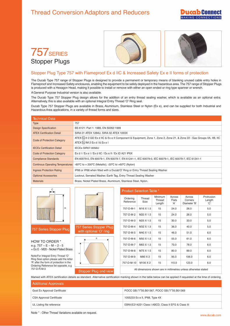
The Ducab Type 757 range of Stopper Plugs is designed to provide a permanent or temporary means of blanking unused cable entry holes in Flameproof and Increased Safety enclosures, enabling the equipment to be safely deployed in the hazardous area. The 757 range of Stopper Plugs is produced with a Hexagon Head, making it possible to install or remove with either an open ended or ring type spanner or wrench.A General Purpose Industrial version is also available.The Ducab Type 757 Stopper Plug design allows for the addition of an entry thread sealing washer, which is available as an optional extra. Alternatively, this is also available with an optional Integral Entry Thread ‘O’ Ring seal.Ducab Type 757 Stopper Plugs are available in Brass, Aluminium, Stainless Steel or Nylon (Ex e), and can be supplied for both Industrial and Hazardous Area applications, in a variety of thread forms and sizes.
Stopper PlugsStopper Plug Type 757 with Flameproof Ex d IIC & Increased Safety Ex e II forms of protection
Marked with ATEX certification details as standard. Alternative certification marking shown in the table below can be applied if requested at the time of ordering.
Type 757Design Specification BS 6121: Part 1: 1989, EN 50262:1999
ATEX Certification Detail SIRA 01 ATEX 1284U, SIRA 02 ATEX 1003X
Code of Protection CategoryATEX II 2 GD Ex d IIC & Ex e II Component & Equipment, Zone 1, Zone 2, Zone 21, & Zone 22 - Gas Groups IIA, IIB, IICATEX IM 2 Ex d I & Ex e I
IECEx Certification Detail IECEx SIR07.0056U
Code of Protection Category Ex d I / Ex e I / Ex d IIC / Ex e II / Ex tD A21 IP6X
Compliance Standards EN 60079-0, EN 60079-1, EN 60079-7, EN 61241-1, IEC 60079-0, IEC 60079-1, IEC 60079-7, IEC 61241-1
Continous Operating Temperatures -60ºC to + 200ºC (Metallic), -20ºC to +60ºC (Nylon)
Ingress Protection Rating IP66 or IP68 when fitted with a Ducab‘O’ Ring or Entry Thread Sealing Washer
Optional Accessories Locknut, Serrated Washer, Earth Tag, Entry Thread Sealing Washer
Materials Brass, Nickel Plated Brass, Aluminium, Stainless Steel, Nylon.
Note:For Integral Entry Thread ‘O’Ring Seal option please add the letter‘R’ after the form of protection in theOrdering Reference list opposite, e.g757-D-R-M-3
Product Selection Table *
OrderingReference
ThreadSize
MinimumThreadLength
AcrossFlats‘A’
AcrossCorners
Diameter ‘B’
ProtrusionLength
‘C’
757-D-M-1 M16 X 1.5 15 24.0 26.0 5.0
757-D-M-2 M20 X 1.5 15 24.0 26.0 5.0
757-D-M-3 M25 X 1.5 15 30.0 33.0 5.0
757-D-M-4 M32 X 1.5 15 36.0 40.0 5.0
757-D-M-5 M40 X 1.5 15 46.0 51.0 6.0
757-D-M-6 M50 X 1.5 15 55.0 61.0 6.0
757-D-M-7 M63 X 1.5 15 70.0 78.0 6.0
757-D-M-8 M75 X 1.5 15 80.0 89.0 6.0
757-D-M-9 M90 X 2 15 95.0 106.0 6.0
757-D-M-10 M100 X 2 15 110.0 123.0 6.0
All dimensions shown are in millimetres unless otherwise stated
HOW TO ORDER *e.g. 757 – E – M – 2 - 5= Ex E - M20 - Nickel Plated Brass
757 Series Stopper Plug 757 Series Stopper Plugwith optional ‘O’ ring
Stopper Plug end view
B
A
A
C
Note * : Other Thread Variations available on request.
757SERIES
Technica l Data
Additional Approvals
Gost Ex Approval Certificate POCC GB. 05.B01367, POCC GB. 05.B01369
CSA Approval Certificate 1055233 Ex e II, IP68, Type 4X
UL Listing file reference EBNV.E214221 Class I ABCD, Class II EFG & Class III
LLU LLU
Thread Conversion Adaptors and Reducers
www.ducab.com
Stopper Plugs
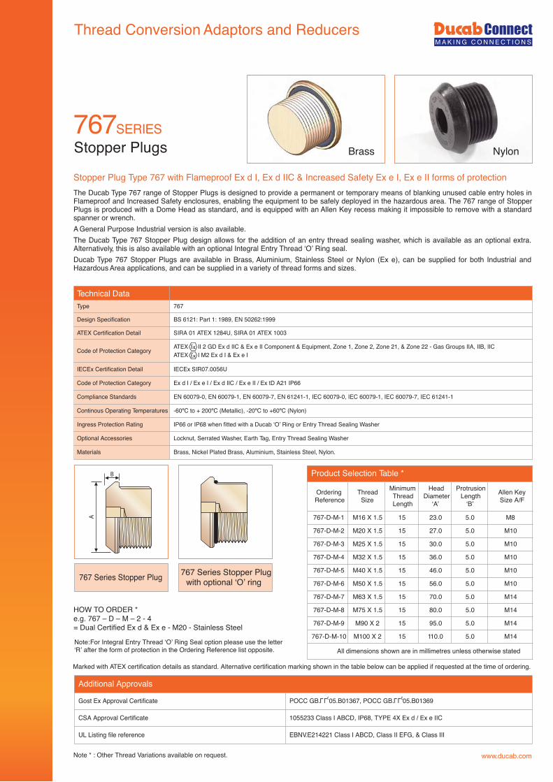
Stopper Plug Type 767 with Flameproof Ex d I, Ex d IIC & Increased Safety Ex e I, Ex e II forms of protection
Technical DataType 767
Design Specification BS 6121: Part 1: 1989, EN 50262:1999
ATEX Certification Detail SIRA 01 ATEX 1284U, SIRA 01 ATEX 1003
Code of Protection Category ATEX II 2 GD Ex d IIC & Ex e II Component & Equipment, Zone 1, Zone 2, Zone 21, & Zone 22 - Gas Groups IIA, IIB, IICATEX I M2 Ex d I & Ex e I
IECEx Certification Detail IECEx SIR07.0056U
Code of Protection Category Ex d I / Ex e I / Ex d IIC / Ex e II / Ex tD A21 IP66
Compliance Standards EN 60079-0, EN 60079-1, EN 60079-7, EN 61241-1, IEC 60079-0, IEC 60079-1, IEC 60079-7, IEC 61241-1
Continous Operating Temperatures -60ºC to + 200ºC (Metallic), -20ºC to +60ºC (Nylon)
Ingress Protection Rating IP66 or IP68 when fitted with a Ducab ‘O’ Ring or Entry Thread Sealing Washer
Optional Accessories Locknut, Serrated Washer, Earth Tag, Entry Thread Sealing Washer
Materials Brass, Nickel Plated Brass, Aluminium, Stainless Steel, Nylon.
Marked with ATEX certification details as standard. Alternative certification marking shown in the table below can be applied if requested at the time of ordering.
767 Series Stopper Plug
Note:For Integral Entry Thread ‘O’ Ring Seal option please use the letter‘R’ after the form of protection in the Ordering Reference list opposite.
HOW TO ORDER *e.g. 767 – D – M – 2 - 4= Dual Certified Ex d & Ex e - M20 - Stainless Steel
767 Series Stopper Plugwith optional ‘O’ ring
Note * : Other Thread Variations available on request.
Product Selection Table *
OrderingReference
ThreadSize
MinimumThreadLength
HeadDiameter
‘A’
ProtrusionLength
‘B’
Allen KeySize A/F
767-D-M-1 M16 X 1.5 15 23.0 5.0 M8
767-D-M-2 M20 X 1.5 15 27.0 5.0 M10
767-D-M-3 M25 X 1.5 15 30.0 5.0 M10
767-D-M-4 M32 X 1.5 15 36.0 5.0 M10
767-D-M-5 M40 X 1.5 15 46.0 5.0 M10
767-D-M-6 M50 X 1.5 15 56.0 5.0 M10
767-D-M-7 M63 X 1.5 15 70.0 5.0 M14
767-D-M-8 M75 X 1.5 15 80.0 5.0 M14
767-D-M-9 M90 X 2 15 95.0 5.0 M14
767-D-M-10 M100 X 2 15 110.0 5.0 M14
All dimensions shown are in millimetres unless otherwise stated
A
B
Brass Nylon
The Ducab Type 767 range of Stopper Plugs is designed to provide a permanent or temporary means of blanking unused cable entry holes in Flameproof and Increased Safety enclosures, enabling the equipment to be safely deployed in the hazardous area. The 767 range of Stopper Plugs is produced with a Dome Head as standard, and is equipped with an Allen Key recess making it impossible to remove with a standard spanner or wrench.A General Purpose Industrial version is also available.The Ducab Type 767 Stopper Plug design allows for the addition of an entry thread sealing washer, which is available as an optional extra. Alternatively, this is also available with an optional Integral Entry Thread ‘O’ Ring seal.Ducab Type 767 Stopper Plugs are available in Brass, Aluminium, Stainless Steel or Nylon (Ex e), can be supplied for both Industrial and Hazardous Area applications, and can be supplied in a variety of thread forms and sizes.
Additional Approvals
Gost Ex Approval Certificate POCC GB. 05.B01367, POCC GB. 05.B01369
CSA Approval Certificate 1055233 Class I ABCD, IP68, TYPE 4X Ex d / Ex e IIC
UL Listing file reference EBNV.E214221 Class I ABCD, Class II EFG, & Class III
LLU LLU
767SERIES
www.ducab.com
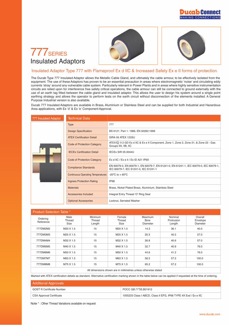
777SERIESInsulated AdaptorsInsulated Adaptor Type 777 with Flameproof Ex d IIC & Increased Safety Ex e II forms of protection.
Product Selection Table *
OrderingReference
MaleThreadSize
MinimumThreadLength
FemaleThreadSize
MaximumBore
Diameter
NominalProtrusion
Length
OverallEnvelopeDiameter
777DM2M2 M20 X 1.5 15 M20 X 1.5 14.3 36.1 40.0
777DM3M3 M25 X 1.5 15 M25 X 1.5 20.3 40.5 57.0
777DM4M4 M32 X 1.5 15 M32 X 1.5 26.8 40.6 57.0
777DM5M5 M40 X 1.5 15 M40 X 1.5 32.7 40.9 76.0
777DM6M6 M50 X 1.5 15 M50 X 1.5 44.6 41.2 76.0
777DM7M7 M63 X 1.5 15 M63 X 1.5 56.5 57.2 100.0
777DM8M8 M75 X 1.5 15 M75 X 1.5 65.2 57.2 100.0
All dimensions shown are in millimetres unless otherwise stated
Marked with ATEX certification details as standard. Alternative certification marking shown in the table below can be applied if requested at the time of ordering.
Note * : Other Thread Variations available on request
Additional ApprovalsGOST R Certificate Number POCC GB. 05.B01912
CSA Approval Certificate 1055233 Class I ABCD, Class II EFG, IP68 TYPE 4X Exd / Ex e IIC
LLU
The Ducab Type 777 Insulated Adaptor allows the Metallic Cable Gland, and ultimately the cable armour, to be effectively isolated from the equipment. The use of these Adaptors has proven to be an essential precaution in areas where electromagnetic ‘noise’ and circulating eddy currents ‘stray’ around any vulnerable cable system. Particularly relevant in Power Plants and in areas where highly sensitive instrumentation circuits are relied upon for interference free safety critical operations, the cable armour can still be connected to ground externally with the use of an earth tag fitted between the cable gland and insulated adaptor. This allows the user to design his system around a single point earthing strategy and allows the operator to perform tests on the earth circuit without disconnection of the elements installed. A General Purpose Industrial version is also available.Ducab 777 Insulated Adaptors are available in Brass, Aluminium or Stainless Steel and can be supplied for both Industrial and Hazardous Area applications, with Ex ‘d’ & Ex ‘e’ Component Approval.
Technical DataType 777
Design Specification BS 6121: Part 1: 1989, EN 50262:1999
ATEX Certification Detail SIRA 05 ATEX 1233U
Code of Protection Category ATEX II 2 GD Ex d IIC & Ex e II Component, Zone 1, Zone 2, Zone 21, & Zone 22 - GasGroups IIA, IIB, IIC
IECEx Certification Detail IECEx SIR 05.0044U
Code of Protection Category Ex d IIC / Ex e II / Ex tD A21 IP6X
Compliance Standards EN 60079-0, EN 60079-1, EN 60079-7, EN 61241-0, EN 61241-1, IEC 60079-0, IEC 60079-1,IEC 60079-7, IEC 61241-0, IEC 61241-1
Continuous Operating Temperatures -20ºC to + 60ºC
Ingress Protection Rating IP68
Materials Brass, Nickel Plated Brass, Aluminium, Stainless Steel
Accessories Included Integral Entry Thread ‘O’ Ring Seal
Optional Accessories Locknut, Serrated Washer
777 Insulated Adaptor
www.ducab.com
Thread Conversion Adaptors and Reducers
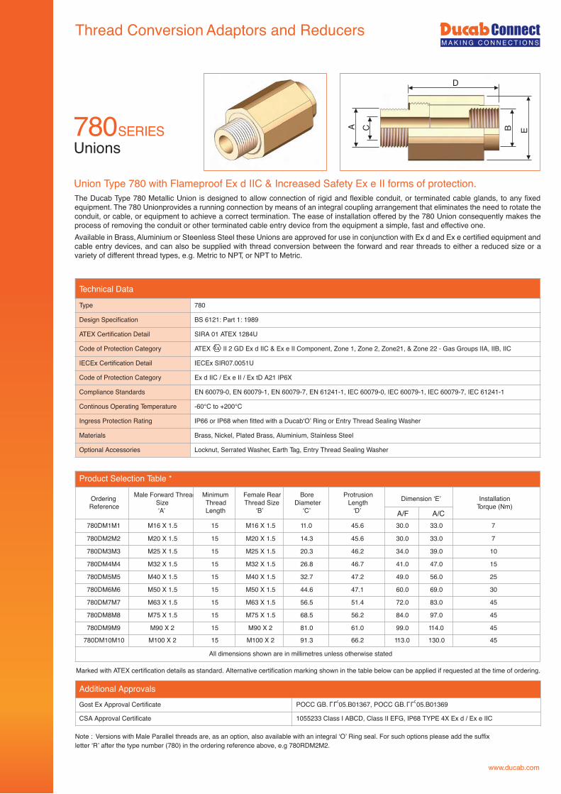
The Ducab Type 780 Metallic Union is designed to allow connection of rigid and flexible conduit, or terminated cable glands, to any fixed equipment. The 780 Unionprovides a running connection by means of an integral coupling arrangement that eliminates the need to rotate the conduit, or cable, or equipment to achieve a correct termination. The ease of installation offered by the 780 Union consequently makes the process of removing the conduit or other terminated cable entry device from the equipment a simple, fast and effective one.Available in Brass, Aluminium or Steenless Steel these Unions are approved for use in conjunction with Ex d and Ex e certified equipment and cable entry devices, and can also be supplied with thread conversion between the forward and rear threads to either a reduced size or a variety of different thread types, e.g. Metric to NPT, or NPT to Metric.
Unions
Union Type 780 with Flameproof Ex d IIC & Increased Safety Ex e II forms of protection.
Marked with ATEX certification details as standard. Alternative certification marking shown in the table below can be applied if requested at the time of ordering.
Note : Versions with Male Parallel threads are, as an option, also available with an integral ‘O’ Ring seal. For such options please add the suffixletter ‘R’ after the type number (780) in the ordering reference above, e.g 780RDM2M2.
Technical Data
Type 780
Design Specification BS 6121: Part 1: 1989
ATEX Certification Detail SIRA 01 ATEX 1284U
Code of Protection Category ATEX II 2 GD Ex d IIC & Ex e II Component, Zone 1, Zone 2, Zone21, & Zone 22 - Gas Groups IIA, IIB, IIC
IECEx Certification Detail IECEx SIR07.0051U
Code of Protection Category Ex d IIC / Ex e II / Ex tD A21 IP6X
Compliance Standards EN 60079-0, EN 60079-1, EN 60079-7, EN 61241-1, IEC 60079-0, IEC 60079-1, IEC 60079-7, IEC 61241-1
Continous Operating Temperature -60°C to +200°C
Ingress Protection Rating IP66 or IP68 when fitted with a Ducab‘O’ Ring or Entry Thread Sealing Washer
Materials Brass, Nickel, Plated Brass, Aluminium, Stainless Steel
Optional Accessories Locknut, Serrated Washer, Earth Tag, Entry Thread Sealing Washer
A B
D
EC
Product Selection Table *
OrderingReference
Male Forward ThreadSize‘A’
MinimumThreadLength
Female RearThread Size
‘B’
BoreDiameter
‘C’
ProtrusionLength
‘D’
Dimension ‘E’ InstallationTorque (Nm)
780DM1M1 M16 X 1.5 15 M16 X 1.5 11.0 45.6 30.0 33.0 7
780DM2M2 M20 X 1.5 15 M20 X 1.5 14.3 45.6 30.0 33.0 7
780DM3M3 M25 X 1.5 15 M25 X 1.5 20.3 46.2 34.0 39.0 10
780DM4M4 M32 X 1.5 15 M32 X 1.5 26.8 46.7 41.0 47.0 15
780DM5M5 M40 X 1.5 15 M40 X 1.5 32.7 47.2 49.0 56.0 25
780DM6M6 M50 X 1.5 15 M50 X 1.5 44.6 47.1 60.0 69.0 30
780DM7M7 M63 X 1.5 15 M63 X 1.5 56.5 51.4 72.0 83.0 45
780DM8M8 M75 X 1.5 15 M75 X 1.5 68.5 56.2 84.0 97.0 45
780DM9M9 M90 X 2 15 M90 X 2 81.0 61.0 99.0 114.0 45
780DM10M10 M100 X 2 15 M100 X 2 91.3 66.2 113.0 130.0 45
All dimensions shown are in millimetres unless otherwise stated
A/F A/C
Additional ApprovalsGost Ex Approval Certificate POCC GB. 05.B01367, POCC GB. 05.B01369
CSA Approval Certificate 1055233 Class I ABCD, Class II EFG, IP68 TYPE 4X Ex d / Ex e IIC
LLU
780SERIES
LLU
www.ducab.com
Thread Conversion Adaptors and Reducers
781SERIES
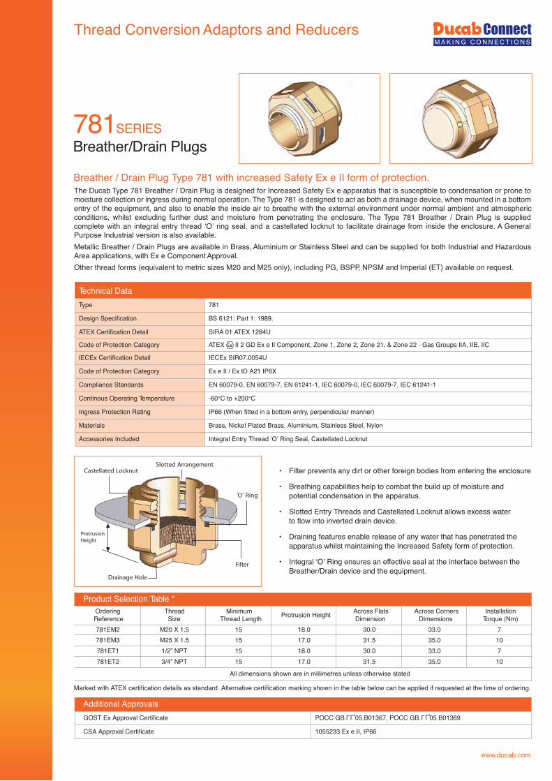
The Ducab Type 781 Breather / Drain Plug is designed for Increased Safety Ex e apparatus that is susceptible to condensation or prone to moisture collection or ingress during normal operation. The Type 781 is designed to act as both a drainage device, when mounted in a bottom entry of the equipment, and also to enable the inside air to breathe with the external environment under normal ambient and atmospheric conditions, whilst excluding further dust and moisture from penetrating the enclosure. The Type 781 Breather / Drain Plug is supplied complete with an integral entry thread ‘O’ ring seal, and a castellated locknut to facilitate drainage from inside the enclosure. A General Purpose Industrial version is also available.Metallic Breather / Drain Plugs are available in Brass, Aluminium or Stainless Steel and can be supplied for both Industrial and Hazardous Area applications, with Ex e Component Approval.Other thread forms (equivalent to metric sizes M20 and M25 only), including PG, BSPP, NPSM and Imperial (ET) available on request.
Breather/Drain Plugs
Marked with ATEX certification details as standard. Alternative certification marking shown in the table below can be applied if requested at the time of ordering.
Product Selection Table *OrderingReference
ThreadSize
MinimumThread Length Protrusion Height Across Flats
DimensionAcross Corners
DimensionsInstallation
Torque (Nm)781EM2 M20 X 1.5 15 18.0 30.0 33.0 7781EM3 M25 X 1.5 15 17.0 31.5 35.0 10781ET1 1/2” NPT 15 18.0 30.0 33.0 7781ET2 3/4” NPT 15 17.0 31.5 35.0 10
All dimensions shown are in millimetres unless otherwise stated
Breather / Drain Plug Type 781 with increased Safety Ex e II form of protection.
Technical DataType 781
Design Specification BS 6121: Part 1: 1989.
ATEX Certification Detail SIRA 01 ATEX 1284U
Code of Protection Category ATEX II 2 GD Ex e II Component, Zone 1, Zone 2, Zone 21, & Zone 22 - Gas Groups IIA, IIB, IIC
IECEx Certification Detail IECEx SIR07.0054U
Code of Protection Category Ex e II / Ex tD A21 IP6X
Compliance Standards EN 60079-0, EN 60079-7, EN 61241-1, IEC 60079-0, IEC 60079-7, IEC 61241-1
Continous Operating Temperature -60°C to +200°C
Ingress Protection Rating IP66 (When fitted in a bottom entry, perpendicular manner)
Materials Brass, Nickel Plated Brass, Aluminium, Stainless Steel, Nylon
Accessories Included Integral Entry Thread ‘O’ Ring Seal, Castellated Locknut
• Filter prevents any dirt or other foreign bodies from entering the enclosure
• Breathing capabilities help to combat the build up of moisture andpotential condensation in the apparatus.
• Slotted Entry Threads and Castellated Locknut allows excess waterto flow into inverted drain device.
• Draining features enable release of any water that has penetrated theapparatus whilst maintaining the Increased Safety form of protection.
• Integral ‘O’ Ring ensures an effective seal at the interface between theBreather/Drain device and the equipment.
Castellated LocknutSlotted Arrangement
‘O’ Ring
Filter
Drainage Hole
ProtrusionHeight
Additional ApprovalsGOST Ex Approval Certificate POCC GB. 05.B01367, POCC GB. 05.B01369
CSA Approval Certificate 1055233 Ex e II, IP66
LLU LLU
www.ducab.com
Thread Conversion Adaptors and Reducers
787SERIES90º Adaptors
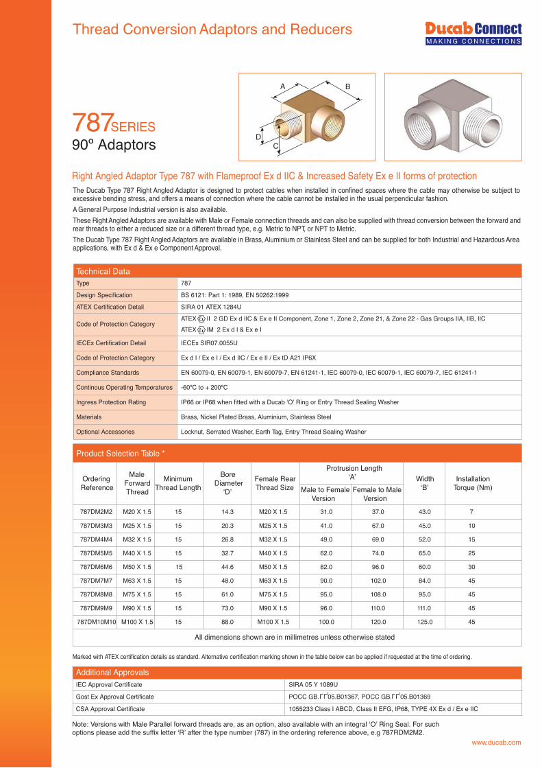
Right Angled Adaptor Type 787 with Flameproof Ex d IIC & Increased Safety Ex e II forms of protection
Marked with ATEX certification details as standard. Alternative certification marking shown in the table below can be applied if requested at the time of ordering.
Note: Versions with Male Parallel forward threads are, as an option, also available with an integral ‘O’ Ring Seal. For suchoptions please add the suffix letter ‘R’ after the type number (787) in the ordering reference above, e.g 787RDM2M2.
CD
A B
Additional ApprovalsIEC Approval Certificate SIRA 05 Y 1089U
Gost Ex Approval Certificate POCC GB. 05.B01367, POCC GB. 05.B01369
CSA Approval Certificate 1055233 Class I ABCD, Class II EFG, IP68, TYPE 4X Ex d / Ex e IIC
LLU LLU
Type 787
Design Specification BS 6121: Part 1: 1989, EN 50262:1999
ATEX Certification Detail SIRA 01 ATEX 1284U
Code of Protection CategoryATEX II 2 GD Ex d IIC & Ex e II Component, Zone 1, Zone 2, Zone 21, & Zone 22 - Gas Groups IIA, IIB, IICATEX IM 2 Ex d I & Ex e I
IECEx Certification Detail IECEx SIR07.0055U
Code of Protection Category Ex d I / Ex e I / Ex d IIC / Ex e II / Ex tD A21 IP6X
Compliance Standards EN 60079-0, EN 60079-1, EN 60079-7, EN 61241-1, IEC 60079-0, IEC 60079-1, IEC 60079-7, IEC 61241-1
Continous Operating Temperatures -60ºC to + 200ºC
Ingress Protection Rating IP66 or IP68 when fitted with a Ducab ‘O’ Ring or Entry Thread Sealing Washer
Materials Brass, Nickel Plated Brass, Aluminium, Stainless Steel
Optional Accessories Locknut, Serrated Washer, Earth Tag, Entry Thread Sealing Washer
Product Selection Table *
OrderingReference
MaleForwardThread
MinimumThread Length
BoreDiameter
‘D’
Female RearThread Size
Protrusion Length‘A’ Width
‘B’Installation
Torque (Nm)Male to FemaleVersion
Female to MaleVersion
787DM2M2 M20 X 1.5 15 14.3 M20 X 1.5 31.0 37.0 43.0 7
787DM3M3 M25 X 1.5 15 20.3 M25 X 1.5 41.0 67.0 45.0 10
787DM4M4 M32 X 1.5 15 26.8 M32 X 1.5 49.0 69.0 52.0 15
787DM5M5 M40 X 1.5 15 32.7 M40 X 1.5 62.0 74.0 65.0 25
787DM6M6 M50 X 1.5 15 44.6 M50 X 1.5 82.0 96.0 60.0 30
787DM7M7 M63 X 1.5 15 48.0 M63 X 1.5 90.0 102.0 84.0 45
787DM8M8 M75 X 1.5 15 61.0 M75 X 1.5 95.0 108.0 95.0 45
787DM9M9 M90 X 1.5 15 73.0 M90 X 1.5 96.0 110.0 111.0 45
787DM10M10 M100 X 1.5 15 88.0 M100 X 1.5 100.0 120.0 125.0 45
All dimensions shown are in millimetres unless otherwise stated
Technical Data
The Ducab Type 787 Right Angled Adaptor is designed to protect cables when installed in confined spaces where the cable may otherwise be subject to excessive bending stress, and offers a means of connection where the cable cannot be installed in the usual perpendicular fashion.A General Purpose Industrial version is also available.These Right Angled Adaptors are available with Male or Female connection threads and can also be supplied with thread conversion between the forward and rear threads to either a reduced size or a different thread type, e.g. Metric to NPT, or NPT to Metric.The Ducab Type 787 Right Angled Adaptors are available in Brass, Aluminium or Stainless Steel and can be supplied for both Industrial and Hazardous Area applications, with Ex d & Ex e Component Approval.
www.ducab.com
Thread Conversion Adaptors and Reducers
Adaptors
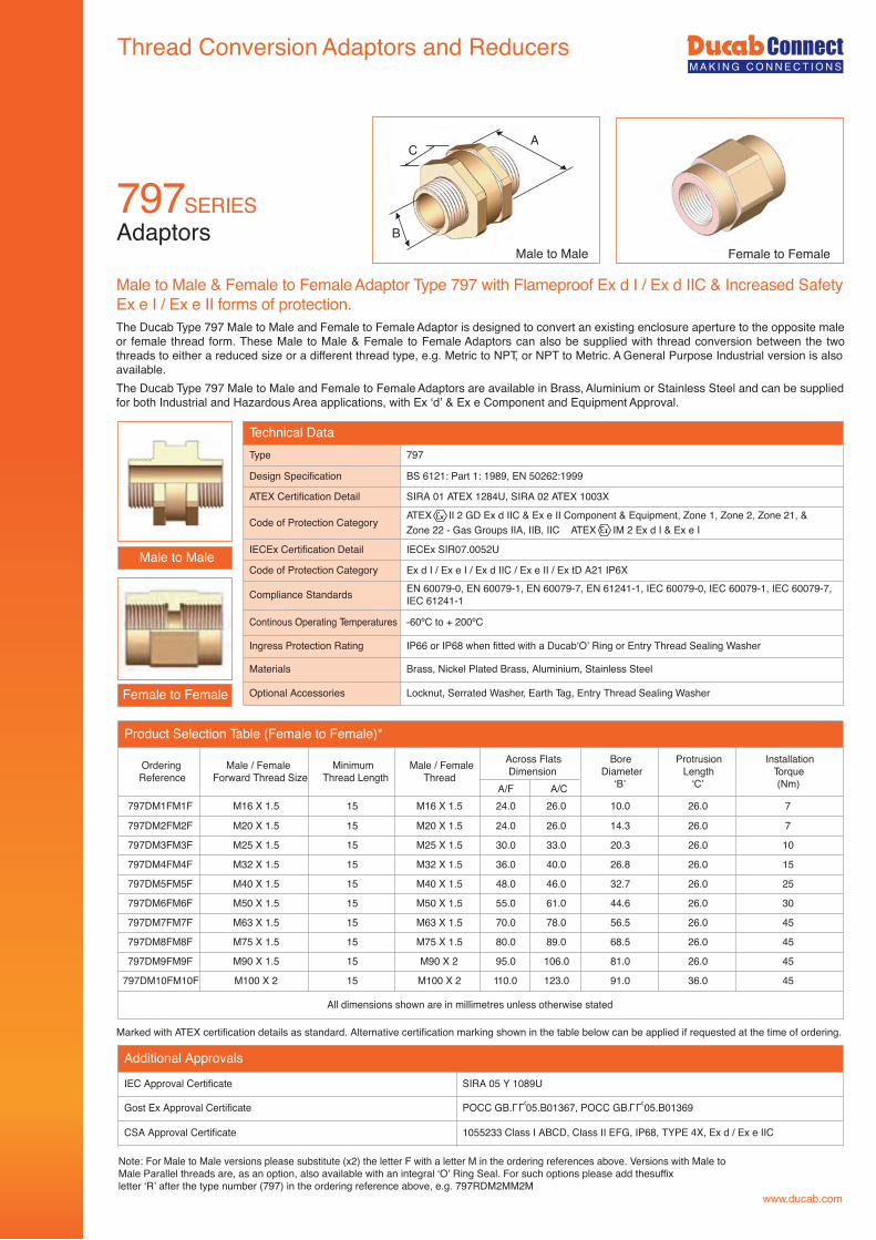
Male to Male & Female to Female Adaptor Type 797 with Flameproof Ex d I / Ex d IIC & Increased SafetyEx e I / Ex e II forms of protection.
Marked with ATEX certification details as standard. Alternative certification marking shown in the table below can be applied if requested at the time of ordering.
Note: For Male to Male versions please substitute (x2) the letter F with a letter M in the ordering references above. Versions with Male toMale Parallel threads are, as an option, also available with an integral ‘O’ Ring Seal. For such options please add thesuffixletter ‘R’ after the type number (797) in the ordering reference above, e.g. 797RDM2MM2M
Technical DataType 797
Design Specification BS 6121: Part 1: 1989, EN 50262:1999
ATEX Certification Detail SIRA 01 ATEX 1284U, SIRA 02 ATEX 1003X
Code of Protection Category ATEX II 2 GD Ex d IIC & Ex e II Component & Equipment, Zone 1, Zone 2, Zone 21, &Zone 22 - Gas Groups IIA, IIB, IIC ATEX IM 2 Ex d I & Ex e I
IECEx Certification Detail IECEx SIR07.0052U
Code of Protection Category Ex d I / Ex e I / Ex d IIC / Ex e II / Ex tD A21 IP6X
Compliance Standards EN 60079-0, EN 60079-1, EN 60079-7, EN 61241-1, IEC 60079-0, IEC 60079-1, IEC 60079-7,IEC 61241-1
Continous Operating Temperatures -60ºC to + 200ºC
Ingress Protection Rating IP66 or IP68 when fitted with a Ducab‘O’ Ring or Entry Thread Sealing Washer
Materials Brass, Nickel Plated Brass, Aluminium, Stainless Steel
Optional Accessories Locknut, Serrated Washer, Earth Tag, Entry Thread Sealing Washer
Male to Male
Female to Female
Male to Male Female to FemaleB
CA
Product Selection Table (Female to Female)*
OrderingReference
Male / FemaleForward Thread Size
MinimumThread Length
Male / FemaleThread
Across FlatsDimension
BoreDiameter
‘B’
ProtrusionLength
‘C’
InstallationTorque(Nm)
797DM1FM1F M16 X 1.5 15 M16 X 1.5 24.0 26.0 10.0 26.0 7
797DM2FM2F M20 X 1.5 15 M20 X 1.5 24.0 26.0 14.3 26.0 7
797DM3FM3F M25 X 1.5 15 M25 X 1.5 30.0 33.0 20.3 26.0 10
797DM4FM4F M32 X 1.5 15 M32 X 1.5 36.0 40.0 26.8 26.0 15
797DM5FM5F M40 X 1.5 15 M40 X 1.5 48.0 46.0 32.7 26.0 25
797DM6FM6F M50 X 1.5 15 M50 X 1.5 55.0 61.0 44.6 26.0 30
797DM7FM7F M63 X 1.5 15 M63 X 1.5 70.0 78.0 56.5 26.0 45
797DM8FM8F M75 X 1.5 15 M75 X 1.5 80.0 89.0 68.5 26.0 45
797DM9FM9F M90 X 1.5 15 M90 X 2 95.0 106.0 81.0 26.0 45
797DM10FM10F M100 X 2 15 M100 X 2 110.0 123.0 91.0 36.0 45
All dimensions shown are in millimetres unless otherwise stated
A/F A/C
The Ducab Type 797 Male to Male and Female to Female Adaptor is designed to convert an existing enclosure aperture to the opposite male or female thread form. These Male to Male & Female to Female Adaptors can also be supplied with thread conversion between the two threads to either a reduced size or a different thread type, e.g. Metric to NPT, or NPT to Metric. A General Purpose Industrial version is also available.The Ducab Type 797 Male to Male and Female to Female Adaptors are available in Brass, Aluminium or Stainless Steel and can be supplied for both Industrial and Hazardous Area applications, with Ex ‘d’ & Ex e Component and Equipment Approval.
797SERIES
Additional Approvals
IEC Approval Certificate SIRA 05 Y 1089U
Gost Ex Approval Certificate POCC GB. 05.B01367, POCC GB. 05.B01369
CSA Approval Certificate 1055233 Class I ABCD, Class II EFG, IP68, TYPE 4X, Ex d / Ex e IIC
LLU LLU
www.ducab.com
Thread Conversion Adaptors and Reducers
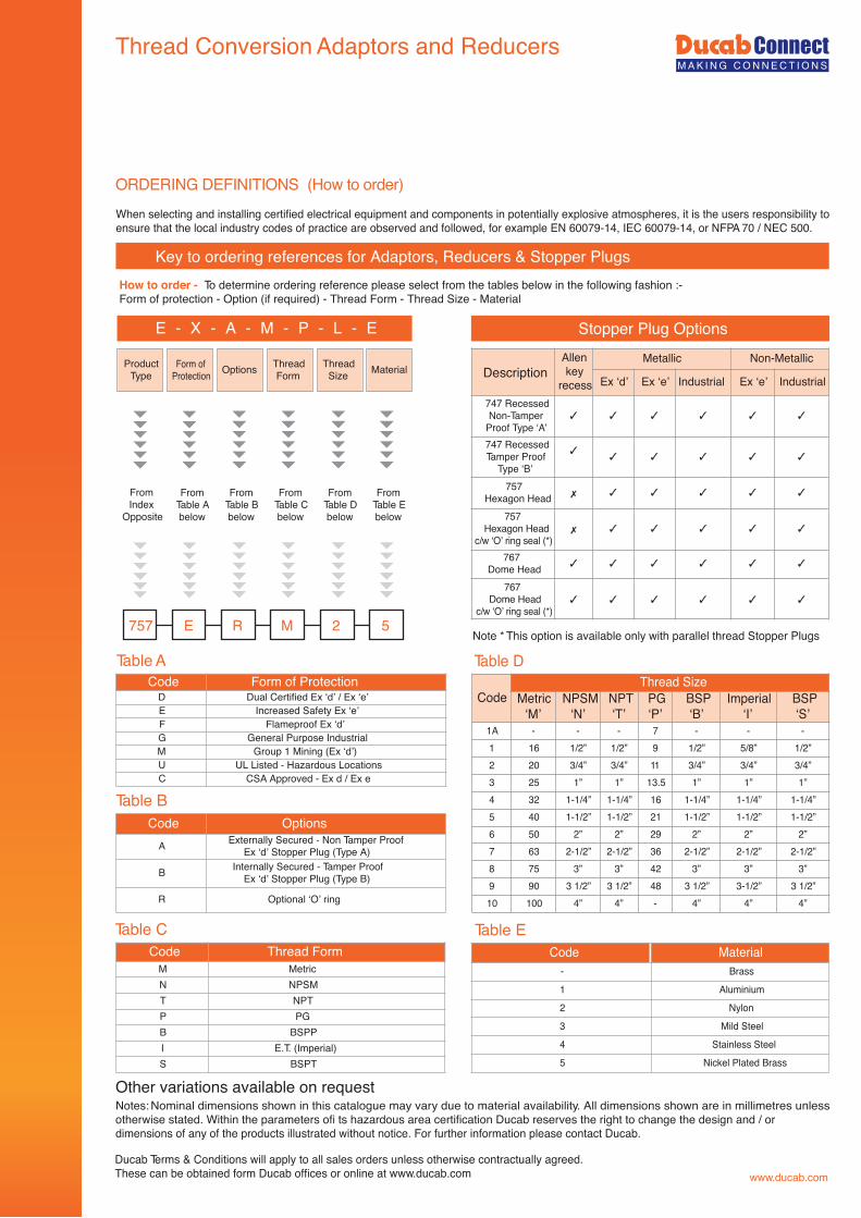
ORDERING DEFINITIONS (How to order)
Code Form of ProtectionD Dual Certified Ex ‘d’ / Ex ‘e’E Increased Safety Ex ‘e’F Flameproof Ex ‘d’G General Purpose IndustrialM Group 1 Mining (Ex ‘d’)U UL Listed - Hazardous LocationsC CSA Approved - Ex d / Ex e
Code OptionsA Externally Secured - Non Tamper Proof
Ex ‘d’ Stopper Plug (Type A)
B Internally Secured - Tamper ProofEx ‘d’ Stopper Plug (Type B)
R Optional ‘O’ ring
Code Thread FormM MetricN NPSMT NPTP PGB BSPPI E.T. (Imperial)S BSPT
Key to ordering references for Adaptors, Reducers & Stopper Plugs
Other variations available on request
How to order - To determine ordering reference please select from the tables below in the following fashion :-Form of protection - Option (if required) - Thread Form - Thread Size - Material
Table A
Table B
Table C
FromIndex
Opposite
FromTable Abelow
FromTable Bbelow
FromTable Cbelow
FromTable Dbelow
FromTable Ebelow
757 E R M 2 5
ProductType
Form ofProtection Options Thread
FormThreadSize Material
E - X - A - M - P - L - E
Notes:
When selecting and installing certified electrical equipment and components in potentially explosive atmospheres, it is the users responsibility toensure that the local industry codes of practice are observed and followed, for example EN 60079-14, IEC 60079-14, or NFPA 70 / NEC 500.
Ducab Terms & Conditions will apply to all sales orders unless otherwise contractually agreed.These can be obtained form Ducab offices or online at www.ducab.com
DescriptionAllenkey
recess
Metallic Non-Metallic
Ex ‘d’ Ex ‘e’ Industrial Ex ‘e’ Industrial
747 RecessedNon-Tamper
Proof Type ‘A’747 RecessedTamper Proof
Type ‘B’757
Hexagon Head757
Hexagon Headc/w ‘O’ ring seal (*)
767Dome Head
767Dome Head
c/w ‘O’ ring seal (*)
Code Material- Brass
1 Aluminium
2 Nylon
3 Mild Steel
4 Stainless Steel
5 Nickel Plated Brass
CodeThread Size
Metric‘M’
NPSM‘N’
NPT‘T’
PG‘P’
BSP‘B’
Imperial‘I’
BSP‘S’
1A - - - 7 - - -1 16 1/2” 1/2” 9 1/2” 5/8” 1/2”2 20 3/4” 3/4” 11 3/4” 3/4” 3/4”3 25 1” 1” 13.5 1” 1” 1”4 32 1-1/4” 1-1/4” 16 1-1/4” 1-1/4” 1-1/4”5 40 1-1/2” 1-1/2” 21 1-1/2” 1-1/2” 1-1/2”6 50 2” 2” 29 2” 2” 2”7 63 2-1/2” 2-1/2” 36 2-1/2” 2-1/2” 2-1/2”8 75 3” 3” 42 3” 3” 3”9 90 3 1/2” 3 1/2” 48 3 1/2” 3-1/2” 3 1/2”10 100 4” 4” - 4” 4” 4”
Table D
Stopper Plug Options
Table E
Note * This option is available only with parallel thread Stopper Plugs
Nominal dimensions shown in this catalogue may vary due to material availability. All dimensions shown are in millimetres unlessotherwise stated. Within the parameters ofi ts hazardous area certification Ducab reserves the right to change the design and / ordimensions of any of the products illustrated without notice. For further information please contact Ducab.
Accessories
www.ducab.com
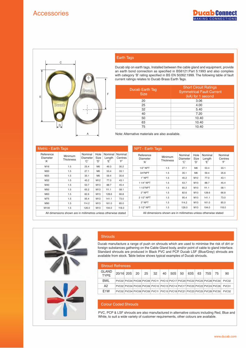
PVC, PCP & LSF shrouds are also manufactured in alternative colours including Red, Blue andWhite, to suit a wide variety of customer requirements, other colours are available.
Shrouds
Colour Coded Shrouds
Ducab Earth TagSize
Short Circuit RatingsSymmetrical Fault Current
(kA) for 1 second20 3.0625 4.0032 5.4040 7.2050 10.4063 10.4075 10.40
Earth Tags
Metric - Earth TagsNominalDiameter
‘C’
HoleSize‘D’
NominalLength
‘E’
NominalCentres
‘F’25.4 M6 49.3 30.2
27.1 M6 53.4 33.1
35.1 M6 59.4 35.6
45.2 M12 77.0 43.1
53.7 M13 88.7 45.4
65.2 M13 111.1 58.1
82.6 M13 128.6 66.8
95.4 M13 141.1 73.0
114.2 M13 161.0 85.0
ReferenceDiameter
‘A’M16
M20
M25
M32
M40
M50
M63
M75
M90
M100
MinimumThickness
1.5
1.5
1.5
1.5
1.5
1.5
1.5
1.5
1.5
1.5 126.0 M13 194.0 118.0
All dimensions shown are in millimetres unless otherwise stated
NPT - Earth TagsNominalDiameter
‘C’
HoleSize‘D’
NominalLength
‘E’
NominalCentres
‘F’
27.1 M6 53.4 33.1
35.1 M6 59.4 35.6
45.2 M12 77.0 43.1
53.7 M13 88.7 45.4
65.2 M13 111.1 58.1
82.6 M13 128.6 66.8
95.4 M13 141.1 73.0
114.2 M13 161.0 85.0
126.0 M13 194.0 118.0
All dimensions shown are in millimetres unless otherwise stated
E
D
A
F
C
GLANDTYPE 20/16 20S 20 25 32 40 50S 50 63S 63 75S 75 90
BWL PVC02 PVC04 PVC06 PVC09 PVC11 PVC13 PVC17 PVC20 PVC22 PVC25 PVC28 PVC30 PVC32
A2 PVC02 PVC04 PVC05 PVC09 PVC10 PVC13 PVC14 PVC17 PVC20 PVC22 PVC24 PVC26 PVC31
E1W PVC02 PVC04 PVC06 PVC09 PVC11 PVC15 PVC18 PVC21 PVC23 PVC25 PVC28 PVC30 PVC32
Shroud Refrences
Ducab slip on earth tags, Installed between the cable gland and equipment, provide an earth bond connection as specified in BS6121:Part 5:1993 and also complies with category ‘B’ rating specified in BS EN 50262:1999. The following table of fault current ratings relates to Ducab Brass Earth Tags.
Note: Alternative materials are also available.
Ducab manufacture a range of push on shrouds which are used to minimise the risk of dirt or foreign substances gathering on the Cable Gland body, and/or point of cable to gland interface. Standard shrouds are produced in Black PVC and PCP. Ducab LSF (Blue/Grey) shrouds are available from stock. Table below shows typical examples of Ducab shrouds.
ReferenceDiameter
‘A’
1/2” NPT
3/4”NPT
1” NPT
1 1/4” NPT
1 1/2”NPT
2” NPT
2 1/2” NPT
3” NPT
3 1/2” NPT
MinimumThickness
1.5
1.5
1.5
1.5
1.5
1.5
1.5
1.5
1.5
Accessories
www.ducab.com
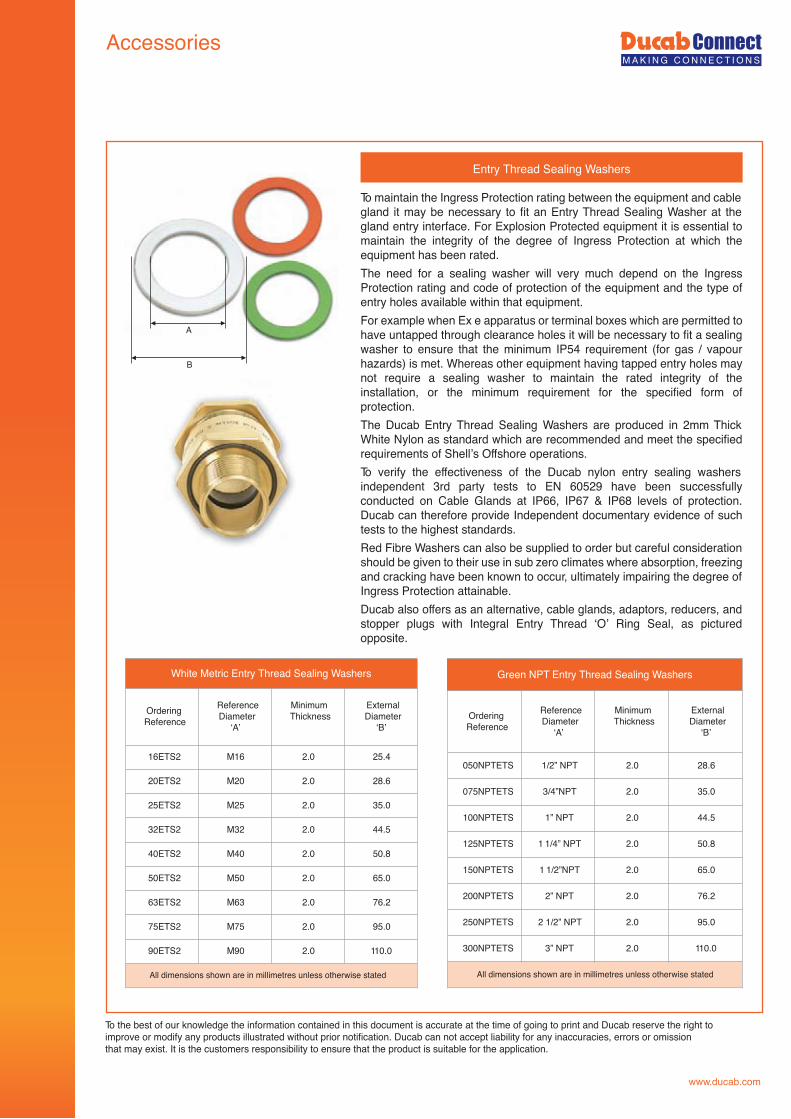
Entry Thread Sealing Washers
White Metric Entry Thread Sealing Washers
OrderingReference
ReferenceDiameter
‘A’
MinimumThickness
ExternalDiameter
‘B’
16ETS2 M16 2.0 25.4
20ETS2 M20 2.0 28.6
25ETS2 M25 2.0 35.0
32ETS2 M32 2.0 44.5
40ETS2 M40 2.0 50.8
50ETS2 M50 2.0 65.0
63ETS2 M63 2.0 76.2
75ETS2 M75 2.0 95.0
90ETS2 M90 2.0 110.0
All dimensions shown are in millimetres unless otherwise stated
OrderingReference
ReferenceDiameter
‘A’
MinimumThickness
ExternalDiameter
‘B’
050NPTETS 1/2” NPT 2.0 28.6
075NPTETS 3/4”NPT 2.0 35.0
100NPTETS 1” NPT 2.0 44.5
125NPTETS 1 1/4” NPT 2.0 50.8
150NPTETS 1 1/2”NPT 2.0 65.0
200NPTETS 2” NPT 2.0 76.2
250NPTETS 2 1/2” NPT 2.0 95.0
300NPTETS 3” NPT 2.0 110.0
All dimensions shown are in millimetres unless otherwise stated
A
B
To maintain the Ingress Protection rating between the equipment and cable gland it may be necessary to fit an Entry Thread Sealing Washer at the gland entry interface. For Explosion Protected equipment it is essential to maintain the integrity of the degree of Ingress Protection at which the equipment has been rated.The need for a sealing washer will very much depend on the Ingress Protection rating and code of protection of the equipment and the type of entry holes available within that equipment.For example when Ex e apparatus or terminal boxes which are permitted to have untapped through clearance holes it will be necessary to fit a sealing washer to ensure that the minimum IP54 requirement (for gas / vapour hazards) is met. Whereas other equipment having tapped entry holes may not require a sealing washer to maintain the rated integrity of the installation, or the minimum requirement for the specified form of protection.The Ducab Entry Thread Sealing Washers are produced in 2mm Thick White Nylon as standard which are recommended and meet the specified requirements of Shell’s Offshore operations.To verify the effectiveness of the Ducab nylon entry sealing washers independent 3rd party tests to EN 60529 have been successfully conducted on Cable Glands at IP66, IP67 & IP68 levels of protection. Ducab can therefore provide Independent documentary evidence of such tests to the highest standards.Red Fibre Washers can also be supplied to order but careful consideration should be given to their use in sub zero climates where absorption, freezing and cracking have been known to occur, ultimately impairing the degree of Ingress Protection attainable.Ducab also offers as an alternative, cable glands, adaptors, reducers, and stopper plugs with Integral Entry Thread ‘O’ Ring Seal, as pictured opposite.
Green NPT Entry Thread Sealing Washers
To the best of our knowledge the information contained in this document is accurate at the time of going to print and Ducab reserve the right toimprove or modify any products illustrated without prior notification. Ducab can not accept liability for any inaccuracies, errors or omissionthat may exist. It is the customers responsibility to ensure that the product is suitable for the application.
Accessories
www.ducab.com
Locknuts
Metric - LocknutsAcross FlatsDimension
‘B’
Across CornersDiameter
‘C’
22.0 25.424.0 28.630.0 35.036.0 42.046.0 53.055.0 64.070.0 81.080.0 98.0108.0 125.0122.0 141.5
All dimensions shown are in millimetres unless otherwise stated
NPT - Locknuts
Across FlatsDimension
‘B’
Across CornersDiameter
‘C’
27.0 29.3
33.0 35.8
41.0 45.0
50.0 53.4
60.0 69.0
70.0 80.2
79.0 90.5
108.0 123.0
114.0 131.0
All dimensions shown are in millimetres unless otherwise stated
Serrated Washers
Metric - Serrated Washers
All dimensions shown are in millimetres unless otherwise stated
NPT - Serrated WashersExternalDiameter
‘B’
32.0
40.0
44.0
59.0
80.0
100.0
112.0
120.0
150.0
All dimensions shown are in millimetres unless otherwise stated
A
A
BB
C
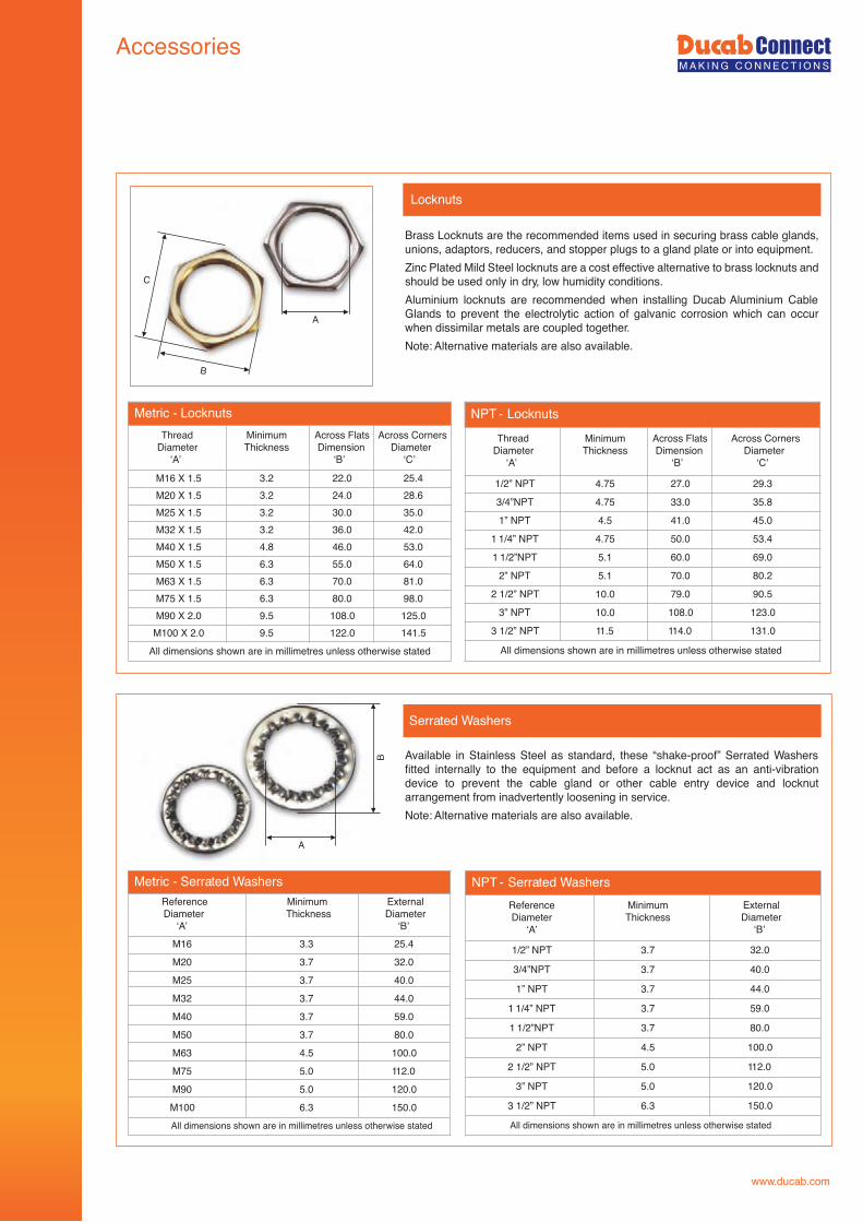
Brass Locknuts are the recommended items used in securing brass cable glands, unions, adaptors, reducers, and stopper plugs to a gland plate or into equipment.Zinc Plated Mild Steel locknuts are a cost effective alternative to brass locknuts and should be used only in dry, low humidity conditions.Aluminium locknuts are recommended when installing Ducab Aluminium Cable Glands to prevent the electrolytic action of galvanic corrosion which can occur when dissimilar metals are coupled together.Note: Alternative materials are also available.
Available in Stainless Steel as standard, these “shake-proof” Serrated Washers fitted internally to the equipment and before a locknut act as an anti-vibration device to prevent the cable gland or other cable entry device and locknut arrangement from inadvertently loosening in service.Note: Alternative materials are also available.
ThreadDiameter
‘A’
MinimumThickness
3.23.23.23.24.86.36.36.39.59.5
ThreadDiameter
‘A’
1/2” NPT
3/4”NPT
1” NPT
1 1/4” NPT
1 1/2”NPT
2” NPT
2 1/2” NPT
3” NPT
3 1/2” NPT
MinimumThickness
4.75
4.75
4.5
4.75
5.1
5.1
10.0
10.0
11.5
ReferenceDiameter
‘A’M16M20M25M32M40M50M63M75M90M100
MinimumThickness
3.33.73.73.73.73.74.55.05.06.3
ExternalDiameter
‘B’25.432.040.044.059.080.0100.0112.0120.0150.0
ReferenceDiameter
‘A’
1/2” NPT
3/4”NPT
1” NPT
1 1/4” NPT
1 1/2”NPT
2” NPT
2 1/2” NPT
3” NPT
3 1/2” NPT
MinimumThickness
3.7
3.7
3.7
3.7
3.7
4.5
5.0
5.0
6.3
M16 X 1.5M20 X 1.5M25 X 1.5M32 X 1.5M40 X 1.5M50 X 1.5M63 X 1.5M75 X 1.5M90 X 2.0
M100 X 2.0
Material and Thread Specifications
www.ducab.com
Material & ThreadSpecification
Brass Extruded bar to EN12168: 1998 Grade CuZn39Pb (CW614N) (Previously BS2874: 1986)
Stainless Steel to EN 10088-2:2005 Grade 316L (Previously BS970 Part 1: 1991)
Mild Steel to BS970 Part 1: 1996 Grade 220MO7Pb
Aluminium Extruded bar to EN573-3:2003 Grade AW6082 & AW6262
Aluminium Castings to EN 1706: 1998 Grade ENAC42000. T6 (Previously BS1490 LM25. TF)
Brass Casting to BS1400: 1985 Grade HTB1
Materials
Metric ISO 965-1, ISO 965-3 medium fit (6g) for external threads
Imperial Conduit (ET) BS 31 : 1940 (1979), Table A
PG DIN 40430 : 1971
BSPP BS 2779 : 1986 (1973) class A full form for external threads
BSPT BS 21 : 1985 standard threads only as clause 5.4, gauging to clause 5.2 system A
ISO ISO 7/1 : 1982, gauging to ISO 7/2 clause 6.3 for external threads
NPT ANSI / ASME B1.20.1 - 1983 gauging to clause 8.1 for external threads
NPSM ANSI / ASME B1.20.1 - 1983 gauging to clause 9 for external threads
Thread Construction Standards
ISO METRIC IEC 60423 PG DIN 40430
THREAD REFERENCE 16 20 25 32 40 50 63 75 THREAD REFERENCE PG7 PG9 PG11 PG13.5 PG16 PG21 PG29 PG36
THREAD SIZE M16 M20 M25 M32 M40 M50 M63 M75 THREAD SIZE PG7 PG9 PG11 PG13.5 PG16 PG21 PG29 PG36
THREAD PITCH 1.5 1.5 1.5 1.5 1.5 1.5 1.5 1.5 THREAD PITCH 1.27 1.41 1.41 1.41 1.41 1.59 1.59 1.59
THREAD PER INCH 16.93 16.93 16.93 16.93 16.93 16.93 16.93 16.93 THREAD PER INCH 20.00 18.00 18.00 18.00 18.00 16.00 16.00 16.00
MAJOR DIAMETER MAX 15.97 19.97 24.97 31.97 39.97 49.97 62.97 74.97 MAJOR DIAMETER MAX 12.5 15.2 18.6 20.4 22.5 28.3 37.0 47.0
CLEARANCE HOLEøMAX 16.5 20.5 25.5 32.5 40.5 50.5 63.5 75.5 CLEARANCE HOLE øMAX 13.0 15.7 19.1 20.9 23.0 28.8 37.5 47.5
NPT ANSI B1.20.1 BSP ISO R/7, BS2779 (BSPP,G,R,PF)
THREAD REFERENCE 050 075 100 125 150 200 250 300 THREAD REFERENCE 050 075 100 125 150 200 250 300
THREAD SIZE 1/2” 3/4” 1” 1 1/4” 1 1/2” 2” 2 1/2” 3” THREAD SIZE 1/2” 3/4” 1” 1 1/4” 1 1/2” 2” 2 1/2” 3”
THREAD PITCH 1.81 1.81 2.20 2.20 2.20 2.20 3.18 3.18 THREAD PITCH 1.81 1.81 2.31 2.31 2.31 2.31 2.31 2.31
THREAD PER INCH 14.00 14.00 11.5 11.5 11.5 11.5 8 8 THREAD PER INCH 14.00 14.00 11.00 11.00 11.00 11.00 11.00 11
MAJOR DIAMETER MAX 21.34 26.67 33.4 42.16 48.26 60.33 73.03 88.9 MAJOR DIAMETER MAX 20.96 26.44 33.25 41.91 47.80 59.61 75.18 87.88
CLEARANCE HOLEøMAX 21.84 27.17 33.9 42.66 48.76 60.83 73.53 89.4 CLEARANCE HOLE øMAX 21.46 26.94 33.75 42.41 48.30 60.11 75.68 88.387
NPS ANSI B1.20.1 BSPT ISO R/7, BS21 (BSPT,GK)
THREAD REFERENCE 050 075 100 125 150 200 250 300 THREAD REFERENCE 050 075 100 125 150 200 250 300
THREAD SIZE 1/2” 3/4” 1” 1 1/4” 1 1/2” 2” 2 1/2” 3” THREAD SIZE 1/2” 3/4” 1” 1 1/4” 1 1/2” 2” 2 1/2” 3”
THREAD PITCH 1.81 1.81 2.20 2.20 2.20 2.20 3.18 3.18 THREAD PITCH 1.81 1.81 2.31 2.31 2.31 2.31 2.31 2.31
THREAD PER INCH 14.00 14.00 11.50 11.50 11.50 11.50 8.00 8.00 THREAD PER INCH 14.00 14.00 11.00 11.00 11.00 11.00 11.00 11
MAJOR DIAMETER MAX 20.9 26.26 32.84 41.6 47.67 59.71 72.16 88.06 MAJOR DIAMETER MAX 20.96 26.44 33.25 41.91 47.80 59.61 75.18 87.88
CLEARANCE HOLEøMAX 21.3 26.76 33.34 42.1 48.17 60.21 72.66 88.56 CLEARANCE HOLE øMAX 21.46 26.94 33.75 42.41 48.30 60.11 75.68 88.387
Ducab Terms & Conditions will apply to all sales orders unless otherwise contractually agreed. These can be obtained form Ducab offices or online at www.ducab.com
www.ducab.com
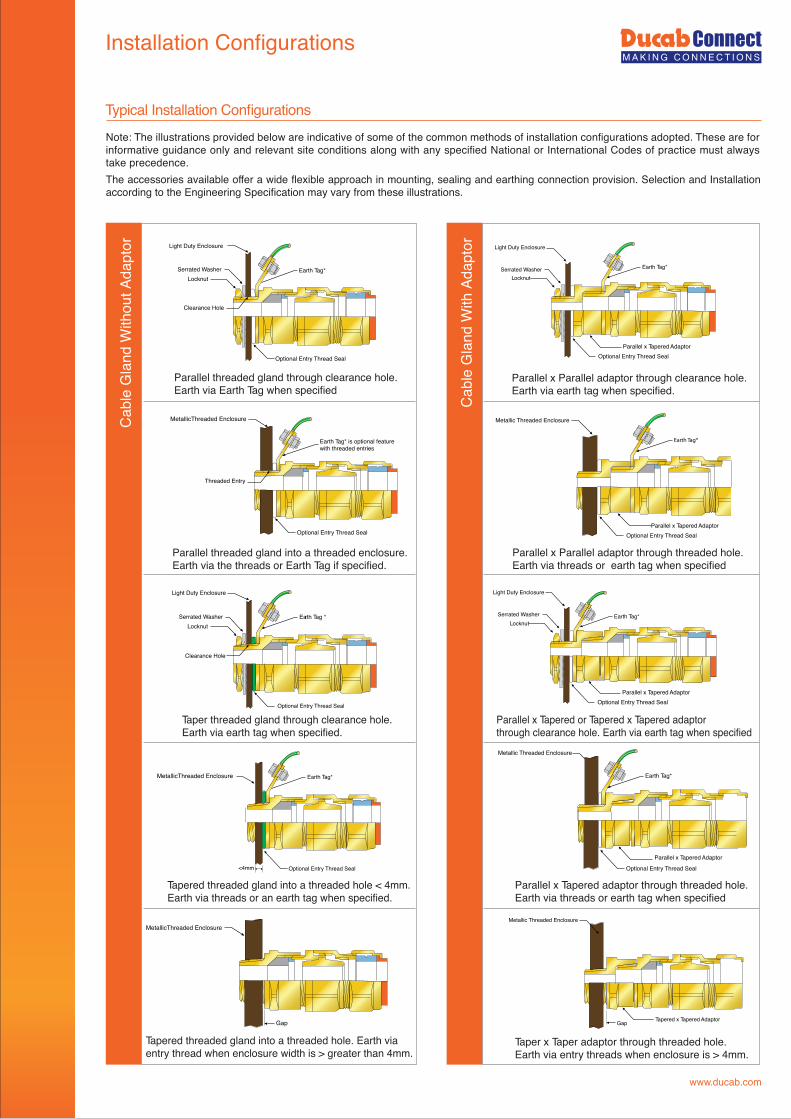
Installation Configurations
Cab
leG
land
With
Adap
tor
Typical Installation Configurations
Parallel threaded gland through clearance hole.Earth via Earth Tag when specified
Parallel x Parallel adaptor through clearance hole.Earth via earth tag when specified.
Parallel threaded gland into a threaded enclosure.Earth via the threads or Earth Tag if specified.
Parallel x Parallel adaptor through threaded hole.Earth via threads or earth tag when specified
Taper threaded gland through clearance hole.Earth via earth tag when specified.
Tapered threaded gland into a threaded hole < 4mm.Earth via threads or an earth tag when specified.
Parallel x Tapered adaptor through threaded hole.Earth via threads or earth tag when specified
Taper x Taper adaptor through threaded hole.Earth via entry threads when enclosure is > 4mm.
Tapered threaded gland into a threaded hole. Earth viaentry thread when enclosure width is > greater than 4mm.
Parallel x Tapered or Tapered x Tapered adaptorthrough clearance hole. Earth via earth tag when specified
Serrated Washer
Light Duty Enclosure
Locknut
Clearance Hole
Earth Tag* Serrated WasherLocknut
Light Duty Enclosure
Earth Tag*
Optional Entry Thread Seal
Earth Tag* is optional featurewith threaded entries
Threaded Entry
Metallic Threaded Enclosure
LocknutEarth Tag * Serrated Washer
Locknut
Light Duty Enclosure
Earth Tag*
Earth Tag*
<4mm
Parallel x Tapered Adaptor
Optional Entry Thread Seal
Metallic Threaded Enclosure
Earth Tag*
MetallicThreaded Enclosure
Gap Tapered x Tapered Adaptor
Metallic Threaded Enclosure
Gap
Cab
leG
land
With
outA
dapt
or
Optional Entry Thread Seal
Parallel x Tapered Adaptor Optional Entry Thread Seal
Parallel x Tapered Adaptor Optional Entry Thread Seal
Parallel x Tapered Adaptor Optional Entry Thread Seal
MetallicThreaded Enclosure
Optional Entry Thread Seal
Optional Entry Thread Seal
MetallicThreaded Enclosure
Light Duty Enclosure
Serrated Washer
Clearance Hole
Note: The illustrations provided below are indicative of some of the common methods of installation configurations adopted. These are for informative guidance only and relevant site conditions along with any specified National or International Codes of practice must always take precedence.The accessories available offer a wide flexible approach in mounting, sealing and earthing connection provision. Selection and Installation according to the Engineering Specification may vary from these illustrations.
Earth Tag*
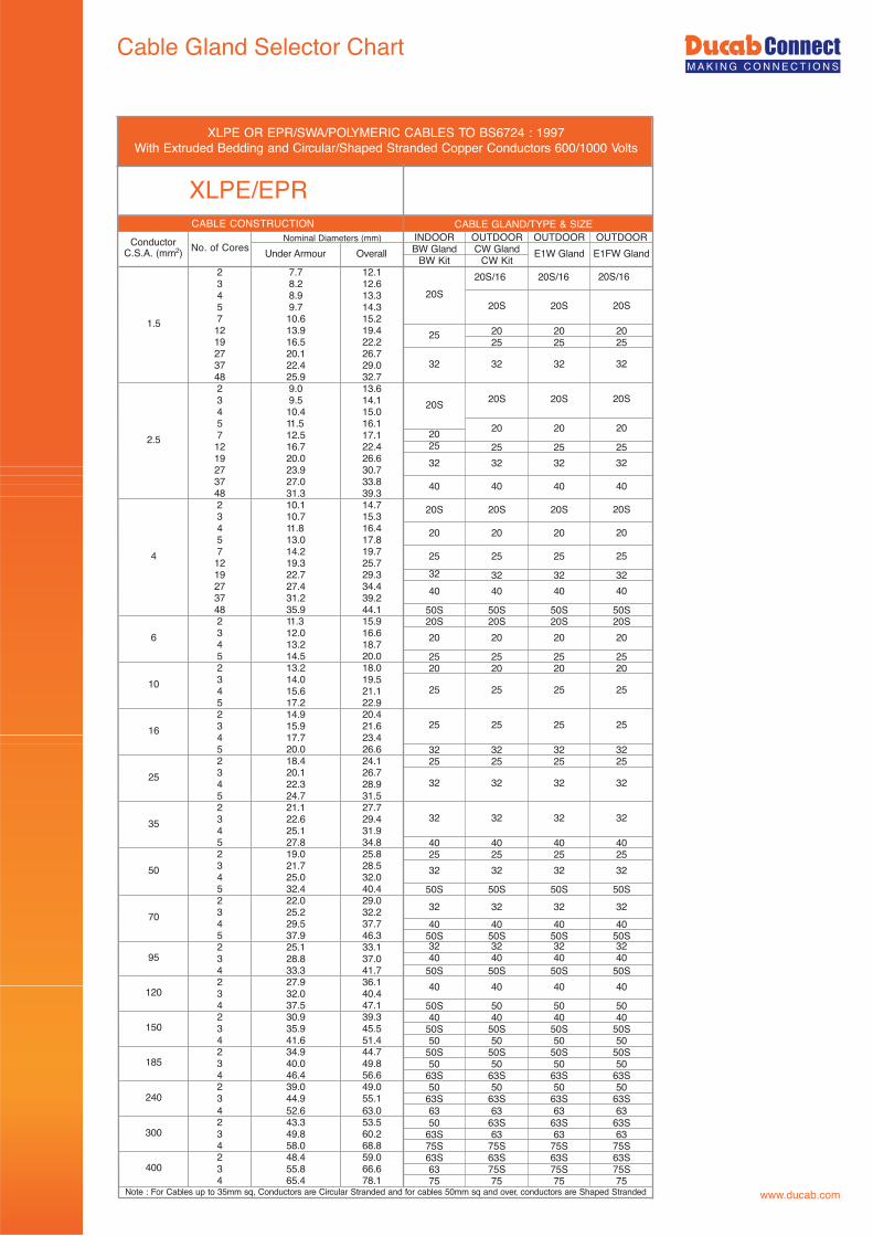
Cable Gland Selector Chart
www.ducab.com
INDOOR OUTDOOR OUTDOOR OUTDOORBW Gland CW Gland
BW Kit CW Kit2 7.7 12.13 8.2 12.64 8.9 13.35 9.7 14.37 10.6 15.212 13.9 19.4 20 20 2019 16.5 22.2 25 25 2527 20.1 26.737 22.4 29.048 25.9 32.72 9.0 13.63 9.5 14.14 10.4 15.05 11.5 16.17 12.5 17.1 2012 16.7 22.4 25 25 25 2519 20.0 26.627 23.9 30.737 27.0 33.848 31.3 39.32 10.1 14.73 10.7 15.34 11.8 16.45 13.0 17.87 14.2 19.712 19.3 25.719 22.7 29.3 32 32 32 3227 27.4 34.437 31.2 39.248 35.9 44.1 50S 50S 50S 50S2 11.3 15.9 20S 20S 20S 20S3 12.0 16.64 13.2 18.75 14.5 20.0 25 25 25 252 13.2 18.0 20 20 20 203 14.0 19.54 15.6 21.15 17.2 22.92 14.9 20.43 15.9 21.64 17.7 23.45 20.0 26.6 32 32 32 322 18.4 24.1 25 25 25 253 20.1 26.74 22.3 28.95 24.7 31.52 21.1 27.73 22.6 29.44 25.1 31.95 27.8 34.8 40 40 40 402 19.0 25.8 25 25 25 253 21.7 28.54 25.0 32.05 32.4 40.4 50S 50S 50S 50S2 22.0 29.03 25.2 32.24 29.5 37.7 40 40 40 405 37.9 46.3 50S 50S 50S 50S2 25.1 33.1 32 32 32 323 28.8 37.0 40 40 40 404 33.3 41.7 50S 50S 50S 50S2 27.9 36.13 32.0 40.44 37.5 47.1 50S 50 50 502 30.9 39.3 40 40 40 403 35.9 45.5 50S 50S 50S 50S4 41.6 51.4 50 50 50 502 34.9 44.7 50S 50S 50S 50S3 40.0 49.8 50 50 50 504 46.4 56.6 63S 63S 63S 63S2 39.0 49.0 50 50 50 503 44.9 55.1 63S 63S 63S 63S4 52.6 63.0 63 63 63 632 43.3 53.5 50 63S 63S 63S3 49.8 60.2 63S 63 63 634 58.0 68.8 75S 75S 75S 75S2 48.4 59.0 63S 63S 63S 63S3 55.8 66.6 63 75S 75S 75S4 65.4 78.1 75 75 75 75
20S
20
25
40
240
300
400
20S/16
20S
32
20S
20
32
40
95
120
150
185
25
35
50
70
4
6
10
16
2.5
40
ConductorC.S.A. (mm2) No. of Cores
Nominal Diameters (mm)CABLE CONSTRUCTION
1.5
Under Armour Overall E1W Gland
32
20S 20S
32 32
20S
E1FW Gland
40 40
32 32 32
32 32 32
20 20
40
25
25
32
32
40
2020
25 25 25
20S 20S
25 25 25
20 20 20
20S 20S
32 32 32
20 20
20S
25
XLPE OR EPR/SWA/POLYMERIC CABLES TO BS6724 : 1997With Extruded Bedding and Circular/Shaped Stranded Copper Conductors 600/1000 Volts
20S/16 20S/16
XLPE/EPR
25 25 25
40 40 40
20S
32 32 32
Note : For Cables up to 35mm sq, Conductors are Circular Stranded and for cables 50mm sq and over, conductors are Shaped Stranded
32 32 32 32
32
40 40
CABLE GLAND/TYPE & SIZE
Cable Gland Selector Chart
www.ducab.com
OUTDOOR OUTDOOR OUTDOOR
1 Pr 7.5 20S/16 20S/16 20S
3 Pr 14.2
7 Pr 19.0
12 Pr 25.5 32 32 32
20 Pr 32.5
27 Pr 36.9
37 Pr 41.8 50 50 50
3 Pr 12.9 20 20 20
7 Pr 17.0 25 25 25
12 Pr 22.6 32 32 32
20 Pr 28.2
27 Pr 32.0
37 Pr 36.1 50S 50S 50S
1 Pr 7.9 20S/16 20S/16 20S
3 Pr 15.2 25 25 25
7 Pr 20.2 32 32 32
12 Pr 27.5 40 40 40
20 Pr 34.7 50S 50S 50S
27 Pr 39.4 50 50 50
37 Pr 44.8 63S 63S 63S
3 Pr 13.6 20 20 20
7 Pr 18.0 25 25 25
12 Pr 24.0 32 32 32
20 Pr 29.9 40 40 40
27 Pr 34.3 50S 50S 50S
37 Pr 38.6 50 50 50
1 Tr 8.1 20S/16 20S/16 20S
3 Tr 15.9 25 25 25
7 Tr 21.4 32 32 32
12 Tr 28.6 40 40 40
3 Tr 14.4
7 Tr 18.8
12 Tr 25.3 32 32 32
1 Tr 8.8 20S 20S 20S
3 Tr 16.9 25 25 25
7 Tr 22.8 32 32 32
12 Tr 30.9 40 40 40
3 Tr 15.2 25 25 25
7 Tr 20.2 32 32 32
12 Tr 26.9 40 40 40
1 Qd 9.4 20S 20S 20S
3 Qds 18.2 25 25 25
7 Qds 25.0 32 32 32
1 Qd 9.9 20S 20S 20S
3 Qds 19.6 25 25 25
7 Qds 31.7 40 40 40
40 40
25 25
25 25
50S 50S
25
50S
40
25
1.0
1.0
0.75
1.0
1.0
1.0
0.75
0.75
CollectivelyScreened
Triples
IndividuallyScreened
Triples
IndividuallyScreened
Quads
CollectivelyScreened
Quads
IndividuallyScreened Pairs
CollectivelyScreened Pairs
IndividuallyScreened
Triples
CollectivelyScreened
Triples
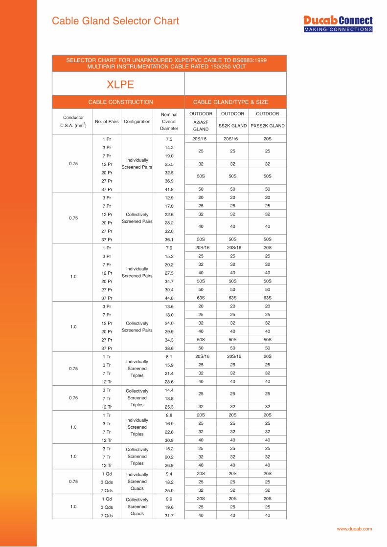
SELECTOR CHART FOR UNARMOURED XLPE/PVC CABLE TO BS6883:1999MULTIPAIR INSTRUMENTATION CABLE RATED 150/250 VOLT
XLPECABLE GLAND/TYPE & SIZE
ConductorC.S.A. (mm2)
No. of Pairs A2/A2FGLAND
SS2K GLAND PXSS2K GLANDConfiguration
CABLE CONSTRUCTION
0.75Individually
Screened Pairs
CollectivelyScreened Pairs
0.75
NominalOverall
Diameter
Cable Gland Selector Chart
www.ducab.com
OUTDOOR OUTDOOR OUTDOOR OUTDOOR
1 Pr 7.5 11.5 20S/16 20S/16 20S/16 20S/16
3 Pr 14.2 18.6
7 Pr 19.0 24.0
12 Pr 25.5 30.7 32 32 32 32
20 Pr 32.5 39.1
27 Pr 36.9 44.1
37 Pr 41.8 49.2 50 50 50 50
3 Pr 12.9 17.3 20 20 20 20
7 Pr 17.0 21.7 25 25 25 25
12 Pr 22.6 27.6 32 32 32 32
20 Pr 28.2 34.7
27 Pr 32.0 38.8
37 Pr 36.1 43.3 50S 50S 50S 50S
1 Pr 7.9 11.9 20S/16 20S/16 20S/16 20S/16
3 Pr 15.2 19.7 25 25 25 25
7 Pr 20.2 25.1 32 32 32 32
12 Pr 27.5 33.8 40 40 40 40
20 Pr 34.7 41.6 50S 50S 50S 50S
27 Pr 39.4 46.7 50 50 50 50
37 Pr 44.8 52.6 63S 63S 63S 63S
3 Pr 13.6 18.0 20 20 20 20
7 Pr 18.0 23.0 25 25 25 25
12 Pr 24.0 29.2 32 32 32 32
20 Pr 29.9 36.7 40 40 40 40
27 Pr 34.3 41.2 50S 50S 50S 50S
37 Pr 38.6 46.0 50 50 50 50
1 Tr 8.1 12.2 20S/16 20S/16 20S/16 20S/16
3 Tr 15.9 21.0 25 25 25 25
7 Tr 21.4 26.4 32 32 32 32
12 Tr 28.6 35.1 40 40 40 40
3 Tr 14.4 18.8
7 Tr 18.8 23.8
12 Tr 25.3 30.9 32 32 32 32
1 Tr 8.8 12.8 20S 20S 20S 20S
3 Tr 16.9 21.7 25 25 25 25
7 Tr 22.8 27.8 32 32 32 32
12 Tr 30.9 37.3 40 40 40 40
3 Tr 15.2 19.8 25 25 25 25
7 Tr 20.2 25.3 32 32 32 32
12 Tr 26.9 33.6 40 40 40 40
1 Qd 9.4 13.4 20S 20S 20S 20S
3 Qds 18.2 23.0 25 25 25 25
7 Qds 25.0 29.8 32 32 32 32
1 Qd 9.9 13.9 20S 20S 20S 20S
3 Qds 19.6 24.6 25 25 25 25
7 Qds 26.7 31.9 40 40 40 40
50S
40
25 25 25
0.75
Individually
Screened
Pairs
Collectively
Screened
Pairs
0.75
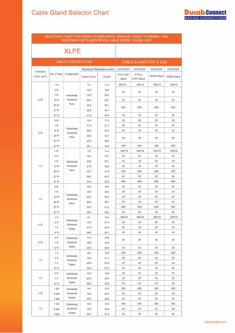
Nominal Diameters (mm)Configuration
CABLE CONSTRUCTION
Conductor
C.S.A. (mm2)No. of Pairs
Under Armour
SELECTOR CHART FOR GSWB OR BWB BRAID ARMOUR CABLE TO BS6883: 1999MULTIPAIR INSTRUMENTATION CABLE RATED 150/250 VOLT
XLPE
PX2KX GlandCX or C2K
Gland
Individually
Screened
Pairs
OverallE1X or
E1FX Gland
25
40
25 25 25
Collectively
Screened
Pairs
Individually
Screened
Triples
Collectively
Screened
Triples
T3CDS Gland
25
40 40
50S 50S 50S
Collectively
Screened
Triples
Individually
Screened
Triples
Individually
Screened
Quads
Collectively
Screened
Quads
1.0
1.0
0.75
0.75
1.0
1.0
0.75
1.0
CABLE GLAND/TYPE & SIZE

Cable Gland Selector Chart
www.ducab.com
INDOOR OUTDOOR OUTDOOR OUTDOORBW Gland CW Gland
BW Kit CW Kit2 8.1 12.53 8.6 13.04 9.4 14.07 11.3 15.912 14.7 20.219 17.5 23.227 21.3 27.937 23.8 30.62 9.0 13.63 9.5 14.14 10.4 15.07 12.5 17.1 20 20 20 2012 16.7 22.4 25 25 25 2519 20.0 26.627 23.9 30.737 27.0 33.8 40 40 40 402 10.1 14.73 10.7 15.34 11.8 16.4 20 20 20 207 14.2 19.712 19.3 25.719 22.7 29.3 32 32 32 3227 27.4 34.437 31.2 39.22 11.3 15.9 20S 20S 20S 20S3 12.0 16.64 13.2 18.72 13.2 18.0 20 20 20 203 14.0 19.54 15.6 21.12 14.5 20.03 15.5 21.2 25 25 25 254 17.2 22.92 18.4 24.1 25 25 25 253 20.1 26.74 22.3 28.92 21.3 27.93 22.8 29.6 32 32 32 324 25.3 32.12 19.0 25.8 25 25 25 253 21.7 28.54 25.0 32.02 22.0 29.03 25.2 32.24 29.5 37.7 40 40 40 402 25.1 33.1 32 32 32 323 28.8 37.0 40 40 40 404 33.3 41.7 50S 50S 50S 50S2 27.9 36.13 32.0 40.44 37.5 47.1 50S 50 50 502 30.9 39.3 40 40 40 403 35.9 45.5 50S 50S 50S 50S4 41.6 51.4 50 50 50 502 34.9 44.7 50S 50S 50S 50S3 40.0 49.8 50 50 50 504 46.4 56.6 63S 63S 63S 63S2 39.0 49.0 50 50 50 503 44.9 55.1 63S 63S 63S 63S4 52.6 63.0 63 63 63 632 43.3 53.5 50 63S 63S 63S3 49.8 60.2 63S 63 63 634 58.0 68.8 75S 75S 75S 75S2 48.4 59.0 63S 63S 63S 63S3 55.8 66.6 63 75S 75S 75S4 65.4 78.1 75 75 75 75
Note : For Cables up to 35mm sq, Conductors are Circular Stranded and for cables 50mm sq and over, conductors are Shaped Stranded
XLPE OR EPR/SWA/PVC CABLES TO BS5467 : 1997
40 40 40
20S/16 20S/16 20S/16
32 32 32
32 32 32
25 25 25
32 32 32
25 25 25
20 20 20
40 40 40
32 32 32
20S 20S 20S
25
32 32
20S 20S 20S
With Extruded Bedding and Circular/Shaped Stranded Copper Conductors 600/1000 Volts
20S
25
32
20S 20S
25
CABLE CONSTRUCTION
No. ofCores
Nominal Diameters (mm)
Under Armour OverallConductor
C.S.A. (mm2)
32
20S
25
20S
25
32
32
32
40
E1W Gland E1FW Gland
40
20
25
32
20S
1.5
2.5
4
6
95
120
10
16
25
35
400
150
185
240
300
50
70
XLPE/EPRCABLE GLAND/TYPE & SIZE

Cable Gland Selector Chart
www.ducab.com
PVC/SWA/PVC CABLES TO BS6346 : 1997With Extruded Bedding and Circular/Shaped Stranded Copper Conductors 600/1000 Volts
INDOOR OUTDOOR OUTDOOR OUTDOORBW Gland CW Gland
BW Kit CW Kit2 7.7 12.33 8.2 12.84 8.9 13.57 10.6 15.212 13.9 19.4 20 20 20 2019 16.5 22.2 25 25 25 2527 20.1 26.737 22.4 29.248 25.9 32.92 9.0 13.63 9.5 14.14 10.4 15.07 12.5 18.0 20 20 20 2012 16.7 22.4 25 25 25 2519 20.0 26.627 23.9 30.737 27.0 34.048 31.3 39.52 10.5 15.13 11.2 15.84 12.3 17.8 20 20 20 207 14.8 20.5 25 25 25 2512 20.2 26.819 23.7 30.527 29.1 37.1 40 40 40 4037 32.6 40.848 37.6 46.02 11.7 16.53 12.5 18.04 13.7 19.22 14.4 20.13 15.5 21.24 17.1 22.82 16.2 21.93 17.4 23.14 19.7 26.3 32 32 322 20.1 26.73 21.6 28.24 23.9 30.72 22.4 29.23 24 30.84 26.7 33.7 40 40 40 402 20.8 27.83 23.5 30.54 27.4 35.4 40 40 40 402 23.4 30.4 32 32 32 323 27 354 31 39.22 27.3 35.53 31.1 39.34 35.9 44.3 50S 50S 50S 50S2 29.6 38 40 40 40 403 33.8 42.2 50S 50S 50S 50S4 39.5 49.3 50 50 50 502 32.7 41.3 50S 50S 50S3 37.7 47.5 50 50 504 43.6 53.6 50 63S 63S 63S2 36.6 46.4 50S 50S 50S 50S3 41.9 51.9 50 50 50 504 48.8 59 63S 63S 63S 63S2 41.2 51.2 50 50 50 503 47.6 57.8 63S 63S 63S 63S4 55.1 65.7 63 63 63 632 46 56.4 63S 63S 63S 63S3 52.6 63.2 63 63 63 634 61 72 75S 75S 75S 75S2 51.1 61.9 63 63 63 633 58.6 69.6 75S 75S 75S 75S4 68.4 81.3 - 90 90 90
32
32
185
240
32
40
40
50S
300
400
50
70
120
150
95
10.0
16.0
25
35
1.5
2.5
4.0
6.0
20S/1620S
50S
32
32
40
20S
32
20S
20S
20S
32
32
40
20S
32
50S
20
25
25
32
32
32
40
40
20S/16
20S
32
20S
32
40
20S
32
50S
20
25
25
32
32
32
40
40
20
25
25
Under Armour Overall
PVC
E1W Gland E1FW GlandConductorC.S.A. (mm2 ) No. of Cores
Nominal Diameters (mm)
20S/16
20S
32
20S
32
40
20S
32
50S
20
25
25
40
32
32
32
40
CABLE CONSTRUCTION CABLE GLAND/TYPE & SIZE
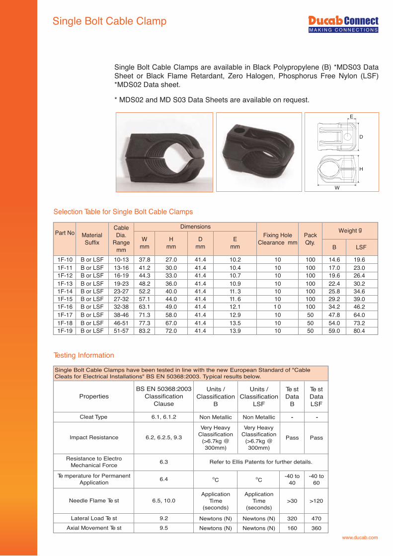
Single Bolt Cable Clamp
Testing Information
Single Bolt Cable Clamps are available in Black Polypropylene (B) *MDS03 Data Sheet or Black Flame Retardant, Zero Halogen, Phosphorus Free Nylon (LSF) *MDS02 Data sheet.
* MDS02 and MD S03 Data Sheets are available on request.
W
H
D
E
Selection Table for Single Bolt Cable Clamps
B LSF
1F-10 B or LSF 10-13 37.8 27.0 41.4 10.2 10 100 14.6 19.61F-11 B or LSF 13-16 41.2 30.0 41.4 10.4 10 100 17.0 23.01F-12 B or LSF 16-19 44.3 33.0 41.4 10.7 10 100 19.6 26.41F-13 B or LSF 19-23 48.2 36.0 41.4 10.9 10 100 22.4 30.21F-14 B or LSF 23-27 52.2 40.0 41.4 11. 3 10 100 25.8 34.61F-15 B or LSF 27-32 57.1 44.0 41.4 11. 6 10 100 29.2 39.01F-16 B or LSF 32-38 63.1 49.0 41.4 12.1 1 0 100 34.2 46.21F-17 B or LSF 38-46 71.3 58.0 41.4 12.9 10 50 47.8 64.01F-18 B or LSF 46-51 77.3 67.0 41.4 13.5 10 50 54.0 73.21F-19 B or LSF 51-57 83.2 72.0 41.4 13.9 10 50 59.0 80.4
Part No Material Suffix
Cable Dia.
Range mm
Fixing Hole Clearance mm
Pack Qty.
Weight gW
mmH
mmD
mm
Dimensions
E mm
Units / Classification
B
Units / Classification
LSF
Te st Data
B
Te st Data LSF
Non Metallic Non Metallic - -
Very Heavy Classification
(>6.7kg @ 300mm)
Very Heavy Classification
(>6.7kg @ 300mm)
Pass Pass
oC oC-40 to
40-40 to
60
Application Time
(seconds)
Application Time
(seconds)>30 >120
Newtons (N) Newtons (N) 320 470Newtons (N) Newtons (N) 160 360
Cleat Type 6.1, 6.1.2
Single Bolt Cable Clamps have been tested in line with the new European Standard of "CableCleats for Electrical Installations" BS EN 50368:2003. Typical results below.
6.5, 10.0
Impact Resistance 6.2, 6.2.5, 9.3
Resistance to Electro Mechanical Force 6.3
PropertiesBS EN 50368:2003
Classification Clause
Axial Movement Te st 9.5Lateral Load Te st 9.2
Refer to Ellis Patents for further details.
Te mperature for Permanent Application 6.4
Needle Flame Te st
www.ducab.com
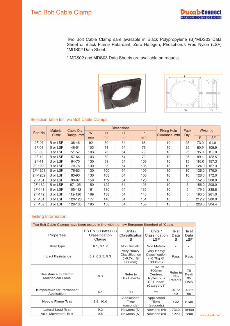
Two Bolt Cable Clamp
Two Bolt Cable Clamp sare available in Black Polypropylene (B)*MDS03 Data Sheet or Black Flame Retardant, Zero Halogen, Phosphorus Free Nylon (LSF) *MDS02 Data Sheet.
* MDS02 and MDS03 Data Sheets are available on request.
www.ducab.com
P
H
DW
Testing Information
Selection Table for Two Bolt Cable Clamps
B LSF2F-07 B or LSF 38-46 92 60 54 68 10 25 73.0 91.02F-08 B or LSF 46-51 103 71 54 79 10 25 80.9 109.92F-09 B or LSF 51-57 103 76 54 79 10 25 95.0 119. 02F-10 B or LSF 57-64 103 82 54 79 10 25 89.1 122.52F-11 B or LSF 64-70 130 89 54 106 10 15 116.0 157.3
2F-1200 B or LSF 70-76 130 95 54 106 10 15 124.0 167.32F-1201 B or LSF 76-83 130 100 54 106 10 10 126.0 170.02F-1202 B or LSF 83-90 130 108 54 106 10 10 128.0 172.02F-131 B or LSF 90-97 150 115 54 126 10 5 152.0 208.02F-132 B or LSF 97-105 150 122 54 126 10 5 156.0 208.02F-141 B or LSF 105-112 161 130 54 135 10 5 179.5 238.82F-142 B or LSF 112-120 169 138 54 143 10 5 193.5 261.02F-151 B or LSF 120-128 177 148 54 151 10 5 212.2 280.02F-152 B or LSF 128-135 185 158 54 158 10 5 228.5 304.4
Part No Material Suffix
Cable Dia. Range mm
DimensionsFixing Hole
Clearance mmPack Qty.
Weight gW
mmH
mmD
mmP
mm
Units / Classification
B
Units / Classification
LSF
Te st Data
B
Te st Data LSF
Non Metallic Non Metallic - -Very Heavy
Classification (>6.7kg @ 300mm)
Very Heavy Classification
(>6.7kg @ 300mm)
Pass Pass
Refer to Ellis Patents.
kA @ 600mm Centres.
Triplex plus SFT Insert
(Category1)
Refer to Ellis
Patents.
78 Peak
35 RMS
oC oC-40 to
40-40 to
60Application
Time (seconds)
Application Time
(seconds)>30 >120
Newtons (N) Newtons (N) 7330 18400Newtons (N) Newtons (N) 1220 1200
PropertiesBS EN 50368:2003
Classification Clause
Cleat Type 6.1, 6.1.2
Impact Resistance 6.2, 6.2.5, 9.3
Resistance to Electro Mechanical Force 6.3
6.5, 10.0
Te mperature for Permanent Application 6.4
Needle Flame Te st
Axial Movement Te st 9.5Lateral Load Te st 9.2
Two Bolt Cable Clamps have been tested in line with the new European Standard of "Cable
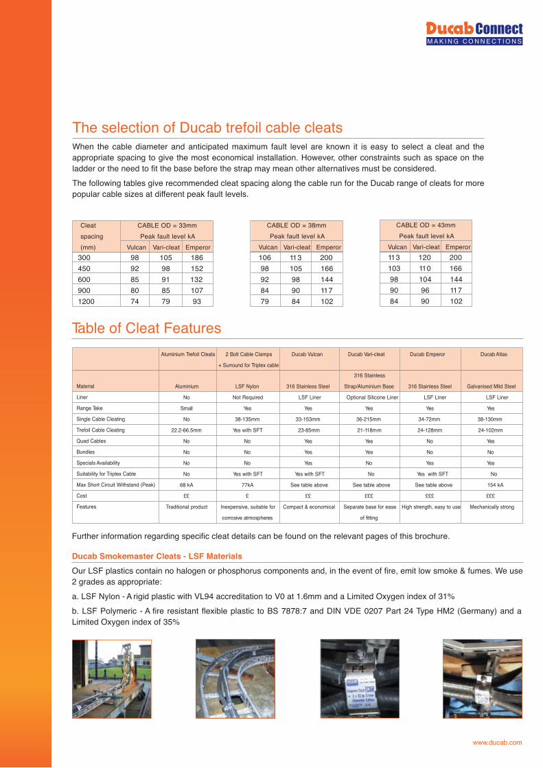
The selection of Ducab trefoil cable cleats
Table of Cleat Features
When the cable diameter and anticipated maximum fault level are known it is easy to select a cleat and the appropriate spacing to give the most economical installation. However, other constraints such as space on the ladder or the need to fit the base before the strap may mean other alternatives must be considered.The following tables give recommended cleat spacing along the cable run for the Ducab range of cleats for more popular cable sizes at different peak fault levels.
Further information regarding specific cleat details can be found on the relevant pages of this brochure.
Ducab Smokemaster Cleats - LSF Materials Our LSF plastics contain no halogen or phosphorus components and, in the event of fire, emit low smoke & fumes. We use 2 grades as appropriate:a. LSF Nylon - A rigid plastic with VL94 accreditation to V0 at 1.6mm and a Limited Oxygen index of 31%b. LSF Polymeric - A fire resistant flexible plastic to BS 7878:7 and DIN VDE 0207 Part 24 Type HM2 (Germany) and a Limited Oxygen index of 35%
300 98 105 186450 92 98 152600 85 91 132900 80 85 1071200 74 79 93
Cleat CABLE OD = 33mmspacing Peak fault level kA(mm) Vulcan Vari-cleat Emperor
113 120 200103 110 16698 104 14490 96 11784 90 102
CABLE OD = 43mmPeak fault level kA
Vulcan Vari-cleat Emperor106 113 20098 105 16692 98 14484 90 11779 84 102
CABLE OD = 38mmPeak fault level kA
Vulcan Vari-cleat Emperor
Aluminium Trefoil Cleats 2 Bolt Cable Clamps Ducab Vulcan Ducab Vari-cleat Ducab Emperor Ducab Atlas
+ Surround for Triplex cable
316 Stainless
Aluminium LSF Nylon 316 Stainless Steel Strap/Aluminium Base 316 Stainless Steel Galvanised Mild Steel
No Not Required LSF Liner Optional Silicone Liner LSF Liner LSF Liner
seYseYseYseYseYllamS
No 38-135mm 33-153mm 36-215mm 34-72mm 38-130mm
22.2-66.5mm Yes with SFT 23-85mm 21-118mm 24-128mm 24-102mm
seYoNseYseYoNoN
oNoNseYseYoNoN
seYseYoNseYoNoN
No Yes with SFT Yes with SFT No Yes with SFT No
68 kA 77kA See table above See table above See table above 154 kA
££££££££££££££
Traditional product Inexpensive, suitable for Compact & economical Separate base for ease High strength, easy to use Mechanically strong
gnittif foserehpsomta evisorroc
Material
Liner
Range Take
Single Cable Cleating
Trefoil Cable Cleating
Quad Cables
Bundles
Specials Availability
Suitability for Triplex Cable
Max Short Circuit Withstand (Peak)
Cost
Features
www.ducab.com
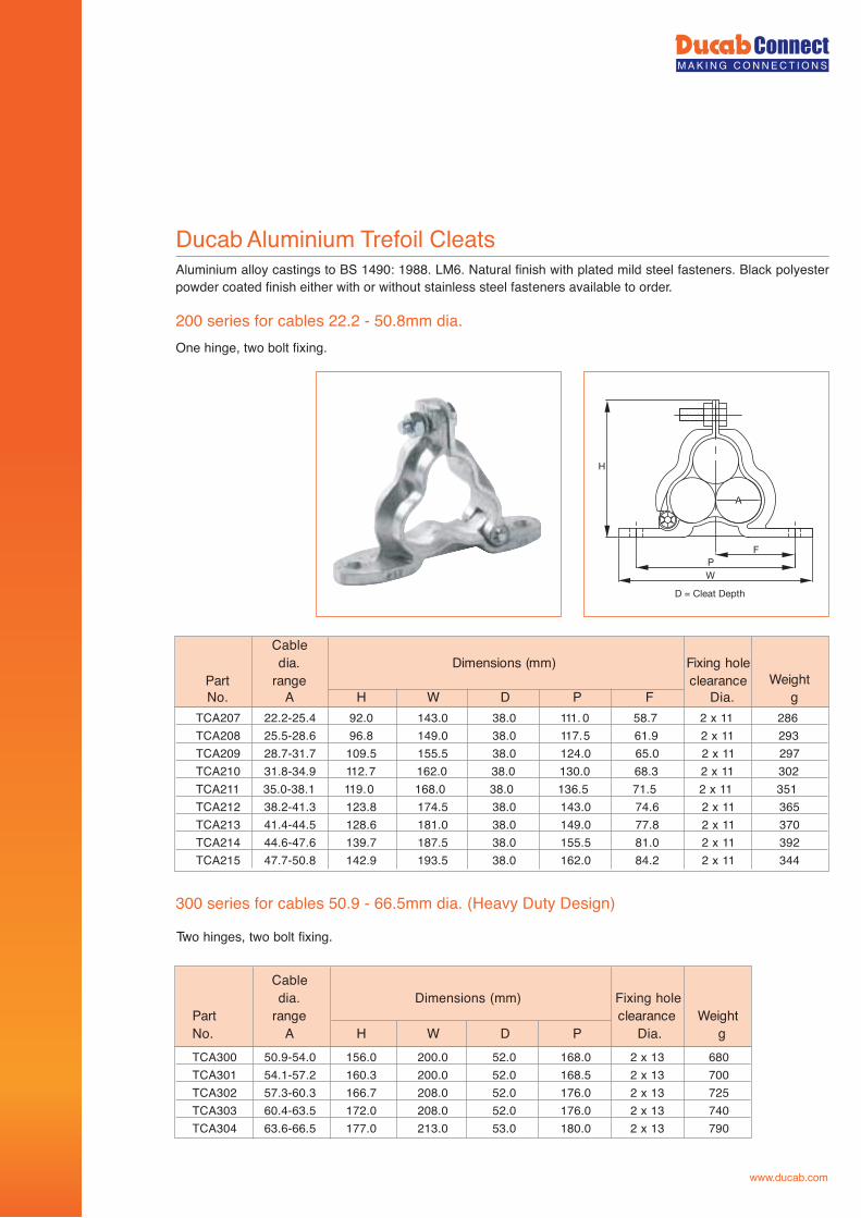
Ducab Aluminium Trefoil CleatsAluminium alloy castings to BS 1490: 1988. LM6. Natural finish with plated mild steel fasteners. Black polyester powder coated finish either with or without stainless steel fasteners available to order.
200 series for cables 22.2 - 50.8mm dia.One hinge, two bolt fixing.
H
P
A
W
F
D = Cleat Depth
300 series for cables 50.9 - 66.5mm dia. (Heavy Duty Design)
TCA207 22.2-25.4 92.0 143.0 38.0 111. 0 58.7 2 x 11 286TCA208 25.5-28.6 96.8 149.0 38.0 117.5 61.9 2 x 11 293TCA209 28.7-31.7 109.5 155.5 38.0 124.0 65.0 2 x 11 297TCA210 31.8-34.9 112.7 162.0 38.0 130.0 68.3 2 x 11 302TCA211 35.0-38.1 119.0 168.0 38.0 136.5 71.5 2 x 11 351TCA212 38.2-41.3 123.8 174.5 38.0 143.0 74.6 2 x 11 365TCA213 41.4-44.5 128.6 181.0 38.0 149.0 77.8 2 x 11 370TCA214 44.6-47.6 139.7 187.5 38.0 155.5 81.0 2 x 11 392TCA215 47.7-50.8 142.9 193.5 38.0 162.0 84.2 2 x 11 344
Cableeloh gnixiF)mm( snoisnemiD.aid
thgieWecnaraelcegnartraPNo. A H W D P F Dia. g
Two hinges, two bolt fixing.
TCA300 50.9-54.0 156.0 200.0 52.0 168.0 2 x 13 680TCA301 54.1-57.2 160.3 200.0 52.0 168.5 2 x 13 700TCA302 57.3-60.3 166.7 208.0 52.0 176.0 2 x 13 725TCA303 60.4-63.5 172.0 208.0 52.0 176.0 2 x 13 740TCA304 63.6-66.5 177.0 213.0 53.0 180.0 2 x 13 790
Cabledia. Dimensions (mm) Fixing hole
thgieWecnaraelcegnartraPNo. A H W D P Dia. g
www.ducab.com
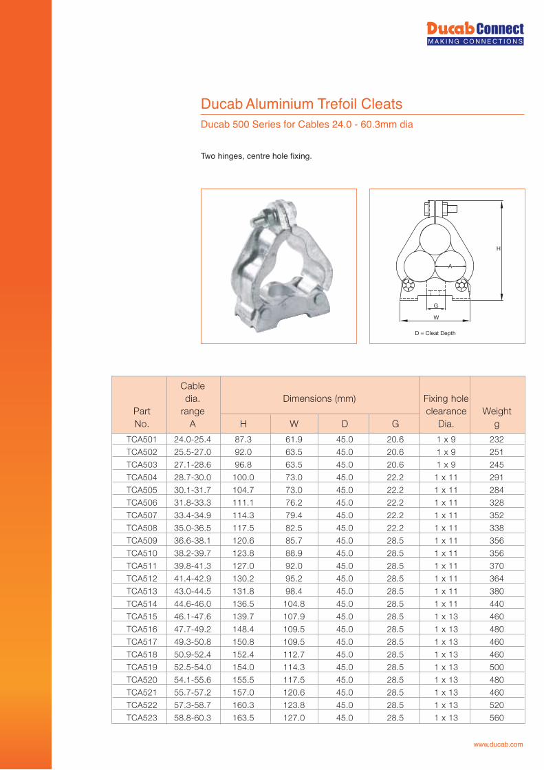
Ducab Aluminium Trefoil CleatsDucab 500 Series for Cables 24.0 - 60.3mm dia
Two hinges, centre hole fixing.
W
H
G
A
D = Cleat Depth
TCA501 24.0-25.4 87.3 61.9 45.0 20.6 1 x 9 232
TCA502 25.5-27.0 92.0 63.5 45.0 20.6 1 x 9 251
TCA503 27.1-28.6 96.8 63.5 45.0 20.6 1 x 9 245
TCA504 28.7-30.0 100.0 73.0 45.0 22.2 1 x 11 291
TCA505 30.1-31.7 104.7 73.0 45.0 22.2 1 x 11 284
TCA506 31.8-33.3 111.1 76.2 45.0 22.2 1 x 11 328
TCA507 33.4-34.9 114.3 79.4 45.0 22.2 1 x 11 352
TCA508 35.0-36.5 117.5 82.5 45.0 22.2 1 x 11 338
TCA509 36.6-38.1 120.6 85.7 45.0 28.5 1 x 11 356
TCA510 38.2-39.7 123.8 88.9 45.0 28.5 1 x 11 356
TCA511 39.8-41.3 127.0 92.0 45.0 28.5 1 x 11 370
TCA512 41.4-42.9 130.2 95.2 45.0 28.5 1 x 11 364
TCA513 43.0-44.5 131.8 98.4 45.0 28.5 1 x 11 380
TCA514 44.6-46.0 136.5 104.8 45.0 28.5 1 x 11 440
TCA515 46.1-47.6 139.7 107.9 45.0 28.5 1 x 13 460
TCA516 47.7-49.2 148.4 109.5 45.0 28.5 1 x 13 480
TCA517 49.3-50.8 150.8 109.5 45.0 28.5 1 x 13 460
TCA518 50.9-52.4 152.4 112.7 45.0 28.5 1 x 13 460
TCA519 52.5-54.0 154.0 114.3 45.0 28.5 1 x 13 500
TCA520 54.1-55.6 155.5 117.5 45.0 28.5 1 x 13 480
TCA521 55.7-57.2 157.0 120.6 45.0 28.5 1 x 13 460
TCA522 57.3-58.7 160.3 123.8 45.0 28.5 1 x 13 520
TCA523 58.8-60.3 163.5 127.0 45.0 28.5 1 x 13 560
Cabledia. Dimensions (mm) Fixing hole
thgieWecnaraelcegnartraPNo. A H W D G Dia. g
www.ducab.com
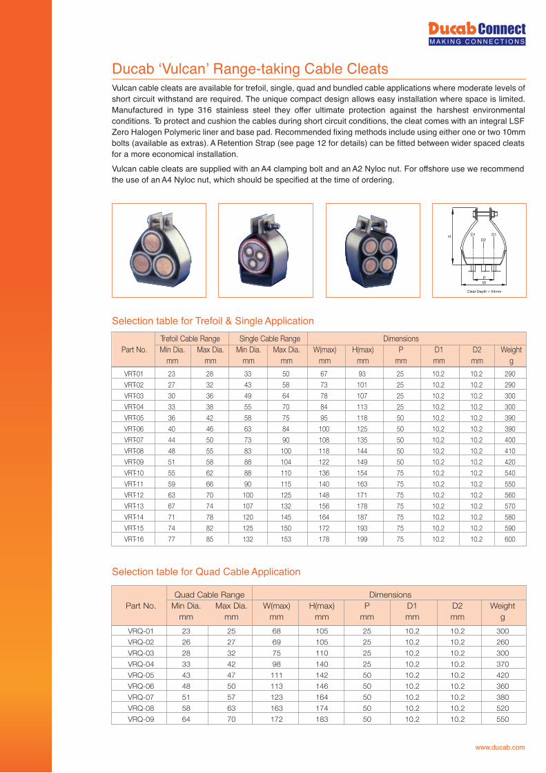
Ducab ‘Vulcan’ Range-taking Cable Cleats
Selection table for Trefoil & Single Application
Vulcan cable cleats are available for trefoil, single, quad and bundled cable applications where moderate levels of short circuit withstand are required. The unique compact design allows easy installation where space is limited. Manufactured in type 316 stainless steel they offer ultimate protection against the harshest environmental conditions. To protect and cushion the cables during short circuit conditions, the cleat comes with an integral LSF Zero Halogen Polymeric liner and base pad. Recommended fixing methods include using either one or two 10mm bolts (available as extras). A Retention Strap (see page 12 for details) can be fitted between wider spaced cleats for a more economical installation.Vulcan cable cleats are supplied with an A4 clamping bolt and an A2 Nyloc nut. For offshore use we recommend the use of an A4 Nyloc nut, which should be specified at the time of ordering.
PW
H
Cleat Depth = 54mm
D1 D1D2
VRT-01 23 28 33 50 67 93 25 10.2 10.2 290
VRT-02 27 32 43 58 73 101 25 10.2 10.2 290
VRT-03 30 36 49 64 78 107 25 10.2 10.2 300
VRT-04 33 38 55 70 84 113 25 10.2 10.2 300
VRT-05 36 42 58 75 95 118 50 10.2 10.2 390
VRT-06 40 46 63 84 100 125 50 10.2 10.2 390
VRT-07 44 50 73 90 108 135 50 10.2 10.2 400
VRT-08 48 55 83 100 118 144 50 10.2 10.2 410
VRT-09 51 58 88 104 122 149 50 10.2 10.2 420
VRT-10 55 62 88 110 136 154 75 10.2 10.2 540
VRT-11 59 66 90 115 140 163 75 10.2 10.2 550
VRT-12 63 70 100 125 148 171 75 10.2 10.2 560
VRT-13 67 74 107 132 156 178 75 10.2 10.2 570
VRT-14 71 78 120 145 164 187 75 10.2 10.2 580
VRT-15 74 82 125 150 172 193 75 10.2 10.2 590
VRT-16 77 85 132 153 178 199 75 10.2 10.2 600
Tr snoisnemiDegnaR elbaC elgniSegnaR elbaC liofePart No. Min Dia. Max Dia. Min Dia. Max Dia. W(max) H(max) P D1 D2 Weight
mm mm mm mm mm mm mm mm mm g
Selection table for Quad Cable Application
VRQ-01 23 25 68 105 25 10.2 10.2 300
VRQ-02 26 27 69 105 25 10.2 10.2 260
VRQ-03 28 32 75 110 25 10.2 10.2 300
VRQ-04 33 42 98 140 25 10.2 10.2 370
VRQ-05 43 47 111 142 50 10.2 10.2 420
VRQ-06 48 50 113 146 50 10.2 10.2 360
VRQ-07 51 57 123 164 50 10.2 10.2 380
VRQ-08 58 63 163 174 50 10.2 10.2 520
VRQ-09 64 70 172 183 50 10.2 10.2 550
snoisnemiDegnaR elbaC dauQPart No. Min Dia. Max Dia. W(max) H(max) P D1 D2 Weight
mm mm mm mm mm mm mm g
www.ducab.com
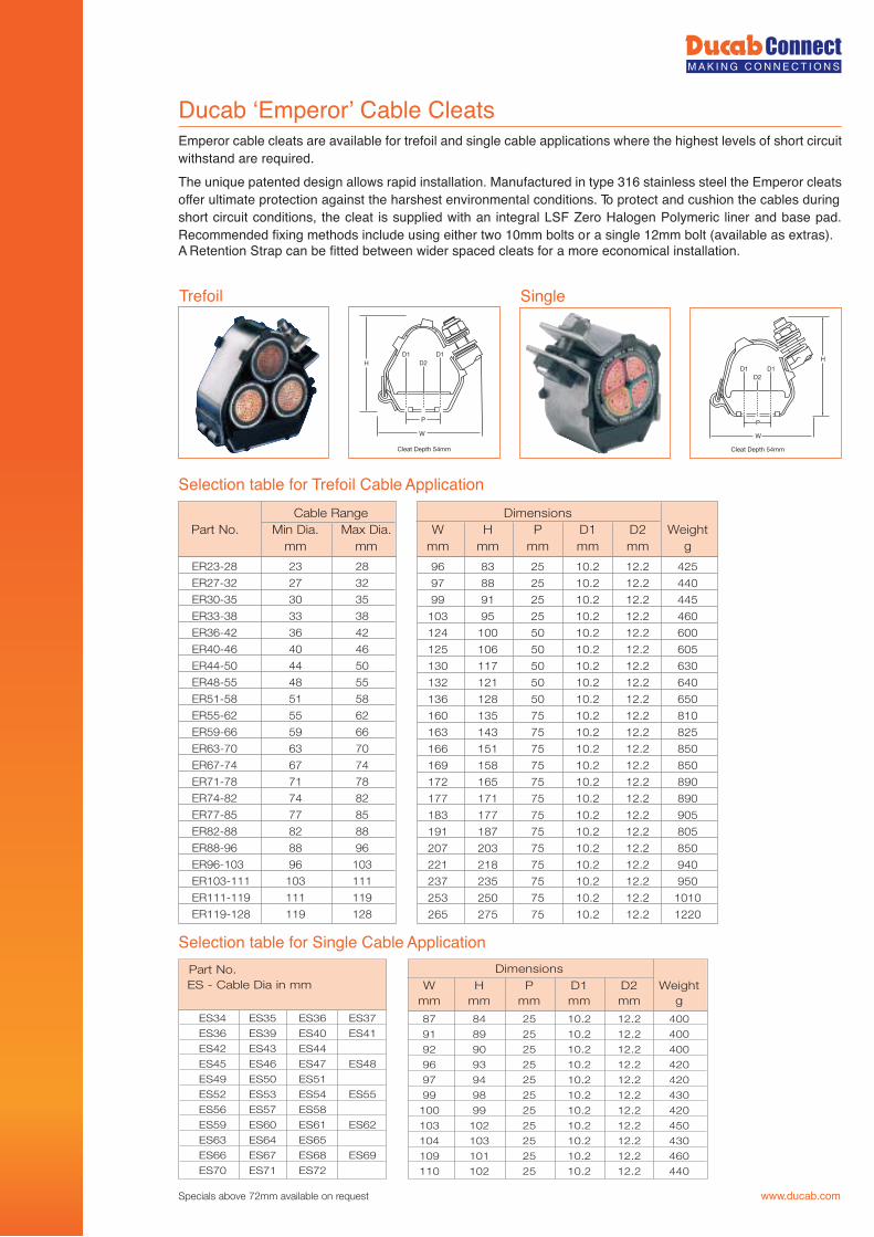
Ducab ‘Emperor’ Cable Cleats
Selection table for Trefoil Cable Application
Emperor cable cleats are available for trefoil and single cable applications where the highest levels of short circuit withstand are required.The unique patented design allows rapid installation. Manufactured in type 316 stainless steel the Emperor cleats offer ultimate protection against the harshest environmental conditions. To protect and cushion the cables during short circuit conditions, the cleat is supplied with an integral LSF Zero Halogen Polymeric liner and base pad. Recommended fixing methods include using either two 10mm bolts or a single 12mm bolt (available as extras).A Retention Strap can be fitted between wider spaced cleats for a more economical installation.
Cleat Depth 54mm
W
P
H
D1 D1D2
Single
Cleat Depth 54mm
D1 D1D2
W
P
H
Trefoil
ER23-28 23 28
ER27-32 27 32
ER30-35 30 35
ER33-38 33 38
ER36-42 36 42
ER40-46 40 46
ER44-50 44 50
ER48-55 48 55
ER51-58 51 58
ER55-62 55 62
ER59-66 59 66
ER63-70 63 70
ER67-74 67 74
ER71-78 71 78
ER74-82 74 82
ER77-85 77 85
ER82-88 82 88
ER88-96 88 96
ER96-103 96 103
ER103-111 103 111
ER111-119 111 119
ER119-128 119 128
96 83 25 10.2 12.2 425
97 88 25 10.2 12.2 440
99 91 25 10.2 12.2 445
103 95 25 10.2 12.2 460
124 100 50 10.2 12.2 600
125 106 50 10.2 12.2 605
130 117 50 10.2 12.2 630
132 121 50 10.2 12.2 640
136 128 50 10.2 12.2 650
160 135 75 10.2 12.2 810
163 143 75 10.2 12.2 825
166 151 75 10.2 12.2 850
169 158 75 10.2 12.2 850
172 165 75 10.2 12.2 890
177 171 75 10.2 12.2 890
183 177 75 10.2 12.2 905
191 187 75 10.2 12.2 805
207 203 75 10.2 12.2 850
221 218 75 10.2 12.2 940
237 235 75 10.2 12.2 950
253 250 75 10.2 12.2 1010
265 275 75 10.2 12.2 1220
Cable Range Part No. Min Dia. Max Dia.
mm mm
DimensionsW H P D1 D2 Weight
mm mm mm mm mm g
Specials above 72mm available on request
ES34 ES35 ES36 ES37
ES36 ES39 ES40 ES41
ES42 ES43 ES44
ES45 ES46 ES47 ES48
ES49 ES50 ES51
ES52 ES53 ES54 ES55
ES56 ES57 ES58
ES59 ES60 ES61 ES62
ES63 ES64 ES65
ES66 ES67 ES68 ES69
ES70 ES71 ES72
87 84 25 10.2 12.2 400
91 89 25 10.2 12.2 400
92 90 25 10.2 12.2 400
96 93 25 10.2 12.2 420
97 94 25 10.2 12.2 420
99 98 25 10.2 12.2 430
100 99 25 10.2 12.2 420
103 102 25 10.2 12.2 450
104 103 25 10.2 12.2 430
109 101 25 10.2 12.2 460
110 102 25 10.2 12.2 440
Part No.ES - Cable Dia in mm
DimensionsW H P D1 D2 Weight
mm mm mm mm mm g
Selection table for Single Cable Application
www.ducab.com
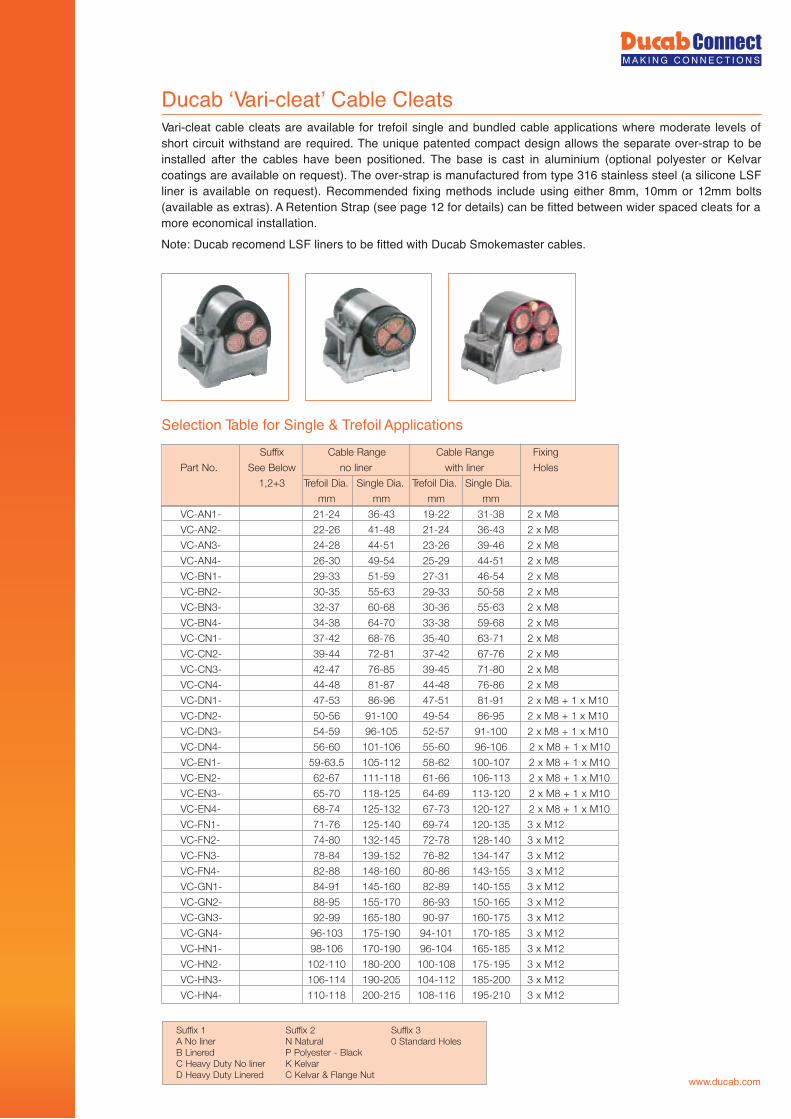
Ducab ‘Vari-cleat’ Cable Cleats
Selection Table for Single & Trefoil Applications
Vari-cleat cable cleats are available for trefoil single and bundled cable applications where moderate levels of short circuit withstand are required. The unique patented compact design allows the separate over-strap to be installed after the cables have been positioned. The base is cast in aluminium (optional polyester or Kelvar coatings are available on request). The over-strap is manufactured from type 316 stainless steel (a silicone LSF liner is available on request). Recommended fixing methods include using either 8mm, 10mm or 12mm bolts (available as extras). A Retention Strap (see page 12 for details) can be fitted between wider spaced cleats for a more economical installation.Note: Ducab recomend LSF liners to be fitted with Ducab Smokemaster cables.
VC-AN1- 21-24 36-43 19-22 31-38 2 x M8
VC-AN2- 22-26 41-48 21-24 36-43 2 x M8
VC-AN3- 24-28 44-51 23-26 39-46 2 x M8
VC-AN4- 26-30 49-54 25-29 44-51 2 x M8
VC-BN1- 29-33 51-59 27-31 46-54 2 x M8
VC-BN2- 30-35 55-63 29-33 50-58 2 x M8
VC-BN3- 32-37 60-68 30-36 55-63 2 x M8
VC-BN4- 34-38 64-70 33-38 59-68 2 x M8
VC-CN1- 37-42 68-76 35-40 63-71 2 x M8
VC-CN2- 39-44 72-81 37-42 67-76 2 x M8
VC-CN3- 42-47 76-85 39-45 71-80 2 x M8
VC-CN4- 44-48 81-87 44-48 76-86 2 x M8
VC-DN1- 47-53 86-96 47-51 81-91 2 x M8 + 1 x M10
VC-DN2- 50-56 91-100 49-54 86-95 2 x M8 + 1 x M10
VC-DN3- 54-59 96-105 52-57 91-100 2 x M8 + 1 x M10
VC-DN4- 56-60 101-106 55-60 96-106 2 x M8 + 1 x M10
VC-EN1- 59-63.5 105-112 58-62 100-107 2 x M8 + 1 x M10
VC-EN2- 62-67 111-118 61-66 106-113 2 x M8 + 1 x M10
VC-EN3- 65-70 118-125 64-69 113-120 2 x M8 + 1 x M10
VC-EN4- 68-74 125-132 67-73 120-127 2 x M8 + 1 x M10
VC-FN1- 71-76 125-140 69-74 120-135 3 x M12
VC-FN2- 74-80 132-145 72-78 128-140 3 x M12
VC-FN3- 78-84 139-152 76-82 134-147 3 x M12
VC-FN4- 82-88 148-160 80-86 143-155 3 x M12
VC-GN1- 84-91 145-160 82-89 140-155 3 x M12
VC-GN2- 88-95 155-170 86-93 150-165 3 x M12
VC-GN3- 92-99 165-180 90-97 160-175 3 x M12
VC-GN4- 96-103 175-190 94-101 170-185 3 x M12
VC-HN1- 98-106 170-190 96-104 165-185 3 x M12
VC-HN2- 102-110 180-200 100-108 175-195 3 x M12
VC-HN3- 106-114 190-205 104-112 185-200 3 x M12
VC-HN4- 110-118 200-215 108-116 195-210 3 x M12
Suffix Cable Range Cable Range Fixing
Part No. See Below no liner with liner Holes
1,2+3 Trefoil Dia. Single Dia. Trefoil Dia. Single Dia.
mm mm mm mm
Suffix 1 Suffix 2 Suffix 3A No liner N Natural 0 Standard HolesB Linered P Polyester - BlackC Heavy Duty No liner K KelvarD Heavy Duty Linered C Kelvar & Flange Nut www.ducab.com
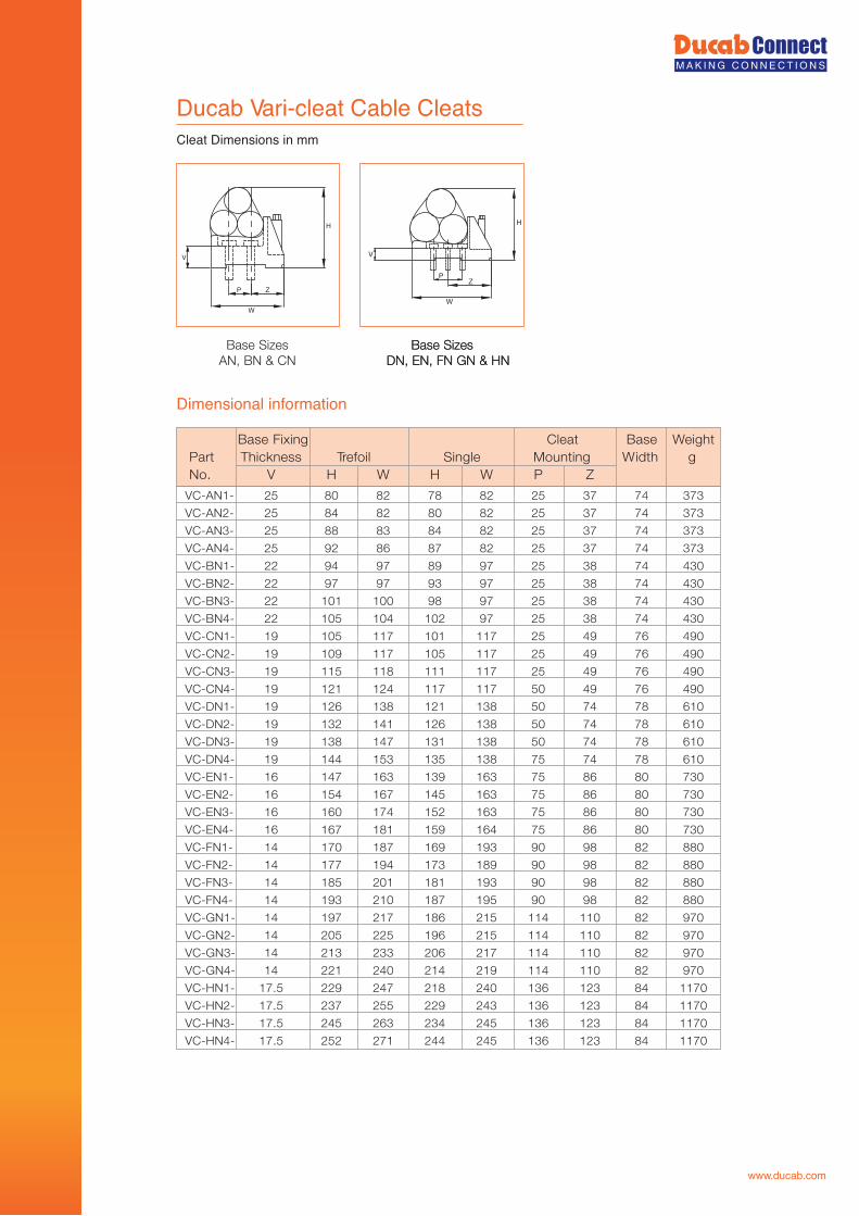
Ducab Vari-cleat Cable CleatsCleat Dimensions in mm
Dimensional information
H
W
ZP
V
Base SizesAN, BN & CN
W
H
PZ
V
Base SizesDN, EN, FN GN & HN
Base SizesDN, EN, FN GN & HN
VC-AN1- 25 80 82 78 82 25 37 74 373
VC-AN2- 25 84 82 80 82 25 37 74 373
VC-AN3- 25 88 83 84 82 25 37 74 373
VC-AN4- 25 92 86 87 82 25 37 74 373
VC-BN1- 22 94 97 89 97 25 38 74 430
VC-BN2- 22 97 97 93 97 25 38 74 430
VC-BN3- 22 101 100 98 97 25 38 74 430
VC-BN4- 22 105 104 102 97 25 38 74 430
VC-CN1- 19 105 117 101 117 25 49 76 490
VC-CN2- 19 109 117 105 117 25 49 76 490
VC-CN3- 19 115 118 111 117 25 49 76 490
VC-CN4- 19 121 124 117 117 50 49 76 490
VC-DN1- 19 126 138 121 138 50 74 78 610
VC-DN2- 19 132 141 126 138 50 74 78 610
VC-DN3- 19 138 147 131 138 50 74 78 610
VC-DN4- 19 144 153 135 138 75 74 78 610
VC-EN1- 16 147 163 139 163 75 86 80 730
VC-EN2- 16 154 167 145 163 75 86 80 730
VC-EN3- 16 160 174 152 163 75 86 80 730
VC-EN4- 16 167 181 159 164 75 86 80 730
VC-FN1- 14 170 187 169 193 90 98 82 880
VC-FN2- 14 177 194 173 189 90 98 82 880
VC-FN3- 14 185 201 181 193 90 98 82 880
VC-FN4- 14 193 210 187 195 90 98 82 880
VC-GN1- 14 197 217 186 215 114 110 82 970
VC-GN2- 14 205 225 196 215 114 110 82 970
VC-GN3- 14 213 233 206 217 114 110 82 970
VC-GN4- 14 221 240 214 219 114 110 82 970
VC-HN1- 17.5 229 247 218 240 136 123 84 1170
VC-HN2- 17.5 237 255 229 243 136 123 84 1170
VC-HN3- 17.5 245 263 234 245 136 123 84 1170
VC-HN4- 17.5 252 271 244 245 136 123 84 1170
thgieW esaBtaelCgnixiF esaBPart Thickness Trefoil Single Mounting Width gNo. V H W H W P Z
www.ducab.com
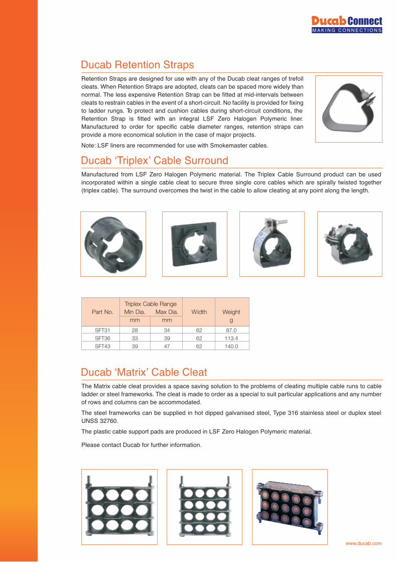
Ducab Retention StrapsRetention Straps are designed for use with any of the Ducab cleat ranges of trefoil cleats. When Retention Straps are adopted, cleats can be spaced more widely than normal. The less expensive Retention Strap can be fitted at mid-intervals between cleats to restrain cables in the event of a short-circuit. No facility is provided for fixing to ladder rungs. To protect and cushion cables during short-circuit conditions, the Retention Strap is fitted with an integral LSF Zero Halogen Polymeric liner. Manufactured to order for specific cable diameter ranges, retention straps can provide a more economical solution in the case of major projects.Note: LSF liners are recommended for use with Smokemaster cables.
Ducab ‘Triplex’ Cable SurroundManufactured from LSF Zero Halogen Polymeric material. The Triplex Cable Surround product can be used incorporated within a single cable cleat to secure three single core cables which are spirally twisted together (triplex cable). The surround overcomes the twist in the cable to allow cleating at any point along the length.
Ducab ‘Matrix’ Cable CleatThe Matrix cable cleat provides a space saving solution to the problems of cleating multiple cable runs to cable ladder or steel frameworks. The cleat is made to order as a special to suit particular applications and any number of rows and columns can be accommodated.The steel frameworks can be supplied in hot dipped galvanised steel, Type 316 stainless steel or duplex steel UNSS 32760.The plastic cable support pads are produced in LSF Zero Halogen Polymeric material.
Please contact Ducab for further information.
Triplex Cable RangePart No. Min Dia. Max Dia. Width Weight
mm mm g
SFT31 28 34 62 87.0
SFT36 33 39 62 113.4
SFT43 39 47 62 140.0
www.ducab.com
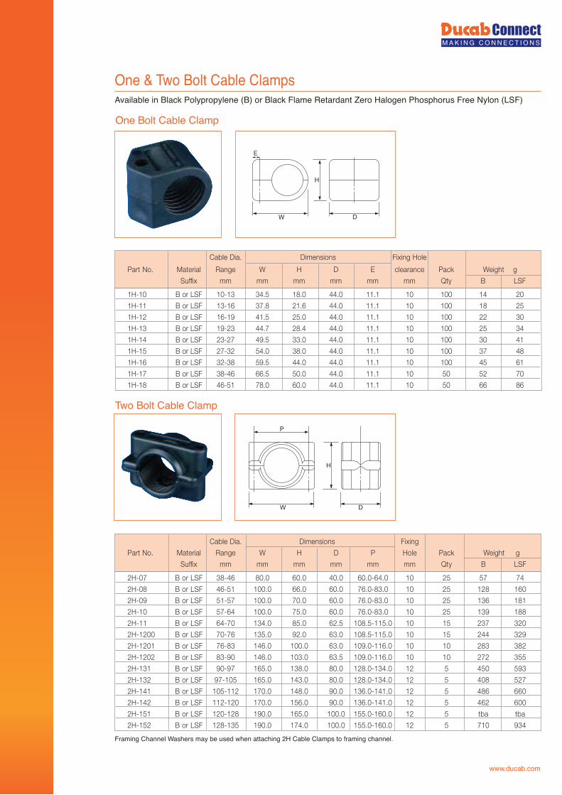
One & Two Bolt Cable ClampsAvailable in Black Polypropylene (B) or Black Flame Retardant Zero Halogen Phosphorus Free Nylon (LSF)
Framing Channel Washers may be used when attaching 2H Cable Clamps to framing channel.
One Bolt Cable Clamp
W D
H
E
1H-10 B or LSF 10-13 34.5 18.0 44.0 11.1 10 100 14 20
1H-11 B or LSF 13-16 37.8 21.6 44.0 11.1 10 100 18 25
1H-12 B or LSF 16-19 41.5 25.0 44.0 11.1 10 100 22 30
1H-13 B or LSF 19-23 44.7 28.4 44.0 11.1 10 100 25 34
1H-14 B or LSF 23-27 49.5 33.0 44.0 11.1 10 100 30 41
1H-15 B or LSF 27-32 54.0 38.0 44.0 11.1 10 100 37 48
1H-16 B or LSF 32-38 59.5 44.0 44.0 11.1 10 100 45 61
1H-17 B or LSF 38-46 66.5 50.0 44.0 11.1 10 50 52 70
1H-18 B or LSF 46-51 78.0 60.0 44.0 11.1 10 50 66 86
Cable Dia. Dimensions Fixing Hole
Part No. Material Range W H D E clearance Pack Weight g
Suffix mm mm mm mm mm mm Qty B LSF
Two Bolt Cable Clamp
W
H
P
D
Cable Dia. Dimensions Fixing
Part No. Material Range W H D P Hole Pack Weight g
Suffix mm mm mm mm mm mm Qty B LSF
2H-07 B or LSF 38-46 80.0 60.0 40.0 60.0-64.0 10 25 57 74
2H-08 B or LSF 46-51 100.0 66.0 60.0 76.0-83.0 10 25 128 160
2H-09 B or LSF 51-57 100.0 70.0 60.0 76.0-83.0 10 25 136 181
2H-10 B or LSF 57-64 100.0 75.0 60.0 76.0-83.0 10 25 139 188
2H-11 B or LSF 64-70 134.0 85.0 62.5 108.5-115.0 10 15 237 320
2H-1200 B or LSF 70-76 135.0 92.0 63.0 108.5-115.0 10 15 244 329
2H-1201 B or LSF 76-83 146.0 100.0 63.0 109.0-116.0 10 10 283 382
2H-1202 B or LSF 83-90 146.0 103.0 63.5 109.0-116.0 10 10 272 355
2H-131 B or LSF 90-97 165.0 138.0 80.0 128.0-134.0 12 5 450 593
2H-132 B or LSF 97-105 165.0 143.0 80.0 128.0-134.0 12 5 408 527
2H-141 B or LSF 105-112 170.0 148.0 90.0 136.0-141.0 12 5 486 660
2H-142 B or LSF 112-120 170.0 156.0 90.0 136.0-141.0 12 5 462 600
2H-151 B or LSF 120-128 190.0 165.0 100.0 155.0-160.0 12 5 tba tba
2H-152 B or LSF 128-135 190.0 174.0 100.0 155.0-160.0 12 5 710 934
www.ducab.com
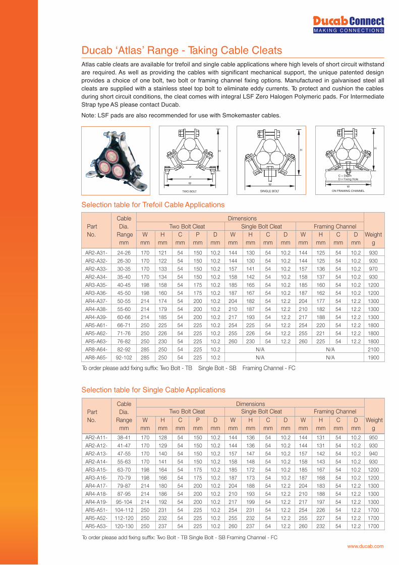
Ducab ‘Atlas’ Range - Taking Cable Cleats
Selection table for Trefoil Cable Applications
Atlas cable cleats are available for trefoil and single cable applications where high levels of short circuit withstand are required. As well as providing the cables with significant mechanical support, the unique patented design provides a choice of one bolt, two bolt or framing channel fixing options. Manufactured in galvanised steel all cleats are supplied with a stainless steel top bolt to eliminate eddy currents. To protect and cushion the cables during short circuit conditions, the cleat comes with integral LSF Zero Halogen Polymeric pads. For Intermediate Strap type AS please contact Ducab.Note: LSF pads are also recommended for use with Smokemaster cables.
ON FRAMING CHANNEL
C = DepthD = Fixing Hole
H
W
SINGLE BOLT
W
H
TWO BOLT
P
H
W
AR2-A31- 24-26 170 121 54 150 10.2 144 130 54 10.2 144 125 54 10.2 930
AR2-A32- 26-30 170 122 54 150 10.2 144 130 54 10.2 144 125 54 10.2 930
AR2-A33- 30-35 170 133 54 150 10.2 157 141 54 10.2 157 136 54 10.2 970
AR2-A34- 35-40 170 134 54 150 10.2 158 142 54 10.2 158 137 54 10.2 930
AR3-A35- 40-45 198 158 54 175 10.2 185 165 54 10.2 185 160 54 10.2 1200
AR3-A36- 45-50 198 160 54 175 10.2 187 167 54 10.2 187 162 54 10.2 1200
AR4-A37- 50-55 214 174 54 200 10.2 204 182 54 12.2 204 177 54 12.2 1300
AR4-A38- 55-60 214 179 54 200 10.2 210 187 54 12.2 210 182 54 12.2 1300
AR4-A39- 60-66 214 185 54 200 10.2 217 193 54 12.2 217 188 54 12.2 1300
AR5-A61- 66-71 250 225 54 225 10.2 254 225 54 12.2 254 220 54 12.2 1800
AR5-A62- 71-76 250 226 54 225 10.2 255 226 54 12.2 255 221 54 12.2 1800
AR5-A63- 76-82 250 230 54 225 10.2 260 230 54 12.2 260 225 54 12.2 1800
0012A/NA/N2.015224505258229-28-46A-8RA
0091A/NA/N2.0152245052582201-29-56A-8RA
snoisnemiDelbaClennahC gnimarF t CleatloB elgniSt CleatloB owT
lennahC gnimarF t CleatloB elgniSt CleatloB owT
.aiDtraPNo. Range W H C P D W H C D W H C D Weight
mm mm mm mm mm mm mm mm mm mm mm mm mm mm g
To order please add fixing suffix: Two Bolt - TB Single Bolt - SB Framing Channel - FC
Selection table for Single Cable Applications
AR2-A11- 38-41 170 128 54 150 10.2 144 136 54 10.2 144 131 54 10.2 950
AR2-A12- 41-47 170 129 54 150 10.2 144 136 54 10.2 144 131 54 10.2 930
AR2-A13- 47-55 170 140 54 150 10.2 157 147 54 10.2 157 142 54 10.2 940
AR2-A14- 55-63 170 141 54 150 10.2 158 148 54 10.2 158 143 54 10.2 930
AR3-A15- 63-70 198 164 54 175 10.2 185 172 54 10.2 185 167 54 10.2 1200
AR3-A16- 70-79 198 166 54 175 10.2 187 173 54 10.2 187 168 54 10.2 1200
AR4-A17- 79-87 214 180 54 200 10.2 204 188 54 12.2 204 183 54 12.2 1300
AR4-A18- 87-95 214 186 54 200 10.2 210 193 54 12.2 210 188 54 12.2 1300
AR4-A19- 95-104 214 192 54 200 10.2 217 199 54 12.2 217 197 54 12.2 1300
AR5-A51- 104-112 250 231 54 225 10.2 254 231 54 12.2 254 226 54 12.2 1700
AR5-A52- 112-120 250 232 54 225 10.2 255 232 54 12.2 255 227 54 12.2 1700
AR5-A53- 120-130 250 237 54 225 10.2 260 237 54 12.2 260 232 54 12.2 1700
snoisnemiDelbaCPart Dia.No. Range W H C P D W H C D W H C D Weight
mm mm mm mm mm mm mm mm mm mm mm mm mm mm g
To order please add fixing suffix: Two Bolt - TB Single Bolt - SB Framing Channel - FC
www.ducab.com
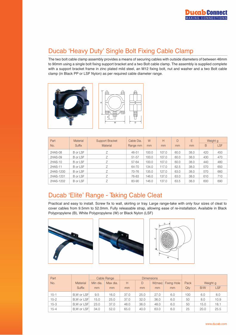
www.ducab.com
Ducab ‘Heavy Duty’ Single Bolt Fixing Cable Clamp The two bolt cable clamp assembly provides a means of securing cables with outside diameters of between 46mm to 90mm using a single bolt fixing support bracket and a two Bolt cable clamp. The assembly is supplied complete with a support bracket frame in zinc plated mild steel, an M12 fixing bolt, nut and washer and a two Bolt cable clamp (in Black PP or LSF Nylon) as per required cable diameter range.
Ducab ‘Elite’ Range - Taking Cable CleatPractical and easy to install. Screw fix to wall, skirting or tray. Large range-take with only four sizes of cleat to cover cables from 9.5mm to 52.0mm. Fully releasable strap, allowing ease of re-installation. Available in Black Polypropylene (B), White Polypropylene (W) or Black Nylon (LSF)
W D
H
E
2HAS-08 B or LSF Z 46-51 100.0 107.0 60.0 38.0 420 450
2HAS-09 B or LSF Z 51-57 100.0 107.0 60.0 38.0 430 470
2HAS-10 B or LSF Z 57-64 100.0 107.0 60.0 38.0 440 480
2HAS-11 B or LSF Z 64-70 134.0 117.0 62.5 38.0 570 650
2HAS-1200 B or LSF Z 70-76 135.0 127.0 63.0 38.0 570 660
2HAS-1201 B or LSF Z 76-83 146.0 137.0 63.0 38.0 610 710
2HAS-1202 B or LSF Z 83-90 146.0 137.0 63.5 38.0 600 690
Part Material Support Bracket Cable Dia. W H D E Weight g
No. Suffix Material Range mm mm mm mm mm B LSF
D
W
H
15-1 B,W or LSF 9.5 16.0 37.0 25.0 27.0 6.0 100 6.0 8.0
15-2 B,W or LSF 15.0 25.0 37.0 32.0 36.0 6.0 50 8.0 10.9
15-3 B,W or LSF 23.0 37.0 48.0 36.0 48.0 6.0 50 15.0 18.1
15-4 B,W or LSF 34.0 52.0 65.0 40.0 63.0 6.0 25 20.0 25.5
snoisnemiDegnaR elbaC traP
No. Material Min dia. Max dia. H D W(max) Fixing Hole Pack Weight g
Suffix mm mm mm mm mm mm Qty B/W LSF
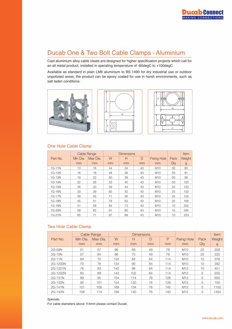
Ducab One & Two Bolt Cable Clamps - AluminiumCast aluminium alloy cable cleats are designed for higher specification projects which call for an all metal product, installed in operating temperature of -60degC to +100degCAvailable as standard in plain LM6 aluminium to BS 1490 for dry industrial use or outdoor unpolluted areas, the product can be epoxy coated for use in harsh environments, such as salt laden conditions.
Specials:For cable diameters above 114mm please contact Ducab.
One Hole Cable Clamp
Two Hole Cable Clamp
W
H
D
P
W
H
D
metIsnoisnemiDegnaR elbaCPart No. Min Dia. Max Dia. W H D Fixing Hole Pack Weight
mm mm mm mm mm mm Qty g1G-11N 13 16 44 34 43 M10 50 80
1G-12N 16 19 48 36 43 M10 50 91
1G-13N 19 22 50 38 43 M10 50 98
1G-14N 22 26 53 40 43 M10 50 100
1G-15N 26 33 59 44 43 M10 25 120
1G-16N 33 39 65 50 43 M10 25 132
1G-17N 39 45 71 56 43 M10 25 152
1G-18N 45 51 78 63 43 M10 25 168
1G-19N 51 58 84 73 43 M10 10 202
1G-20N 58 65 91 80 43 M10 10 189
1G-21N 65 71 97 89 43 M10 10 253
metIsnoisnemiDegnaR elbaCPart No. Min Dia. Max Dia. W H D P Fixing Hole Pack Weight
mm mm mm mm mm mm mm Qty g
2G-09N 51 57 96 68 49 76 M10 25 208
2G-10N 57 64 96 75 49 76 M10 25 220
2G-11N 64 70 134 84 64 114 M10 10 376
2G-1200N 70 76 134 90 64 114 M10 10 392
2G-1201N 76 83 142 96 64 114 M12 10 451
2G-1202N 83 89 142 102 64 114 M12 5 550
2G-131N 89 95 154 114 76 126 M12 5 650
2G-132N 95 101 154 120 76 126 M12 5 750
2G-141N 101 108 169 134 76 140 M12 5 1100
2G-142N 108 114 169 140 76 140 M12 5 1450
www.ducab.com
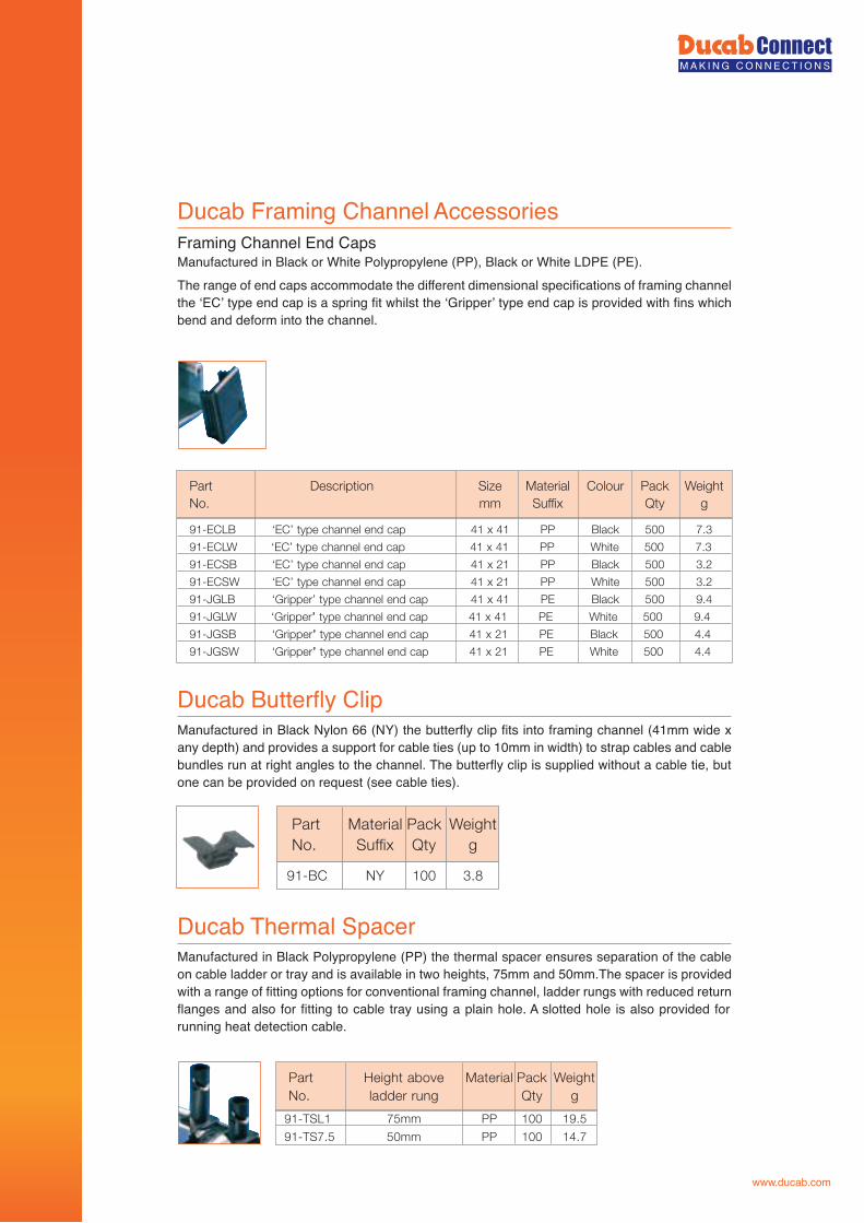
www.ducab.com
Ducab Framing Channel AccessoriesFraming Channel End CapsManufactured in Black or White Polypropylene (PP), Black or White LDPE (PE).The range of end caps accommodate the different dimensional specifications of framing channel the ‘EC’ type end cap is a spring fit whilst the ‘Gripper’ type end cap is provided with fins which bend and deform into the channel.
Ducab Butterfly Clip
91-ECLB ‘EC’ type channel end cap 41 x 41 PP Black 500 7.3
91-ECLW ‘EC’ type channel end cap 41 x 41 PP White 500 7.3
91-ECSB ‘EC’ type channel end cap 41 x 21 PP Black 500 3.2
91-ECSW ‘EC’ type channel end cap 41 x 21 PP White 500 3.2
91-JGLB ‘Gripper’ type channel end cap 41 x 41 PE Black 500 9.4
91-JGLW ‘Gripper’’ type channel end cap 41 x 41 PE White 500 9.4
91-JGSB ‘Gripper’’ type channel end cap 41 x 21 PE Black 500 4.4
91-JGSW ‘Gripper’’ type channel end cap 41 x 21 PE White 500 4.4
Part Description Size Material Colour Pack WeightgytQxiffuSmm.oN
Manufactured in Black Nylon 66 (NY) the butterfly clip fits into framing channel (41mm wide x any depth) and provides a support for cable ties (up to 10mm in width) to strap cables and cable bundles run at right angles to the channel. The butterfly clip is supplied without a cable tie, but one can be provided on request (see cable ties).
Ducab Thermal SpacerManufactured in Black Polypropylene (PP) the thermal spacer ensures separation of the cable on cable ladder or tray and is available in two heights, 75mm and 50mm.The spacer is provided with a range of fitting options for conventional framing channel, ladder rungs with reduced return flanges and also for fitting to cable tray using a plain hole. A slotted hole is also provided for running heat detection cable.
91-BC NY 100 3.8
Part Material Pack WeightNo. Suffix Qty g
91-TSL1 75mm PP 100 19.5
91-TS7.5 50mm PP 100 14.7
Part Height above Material Pack WeightNo. ladder rung Qty g
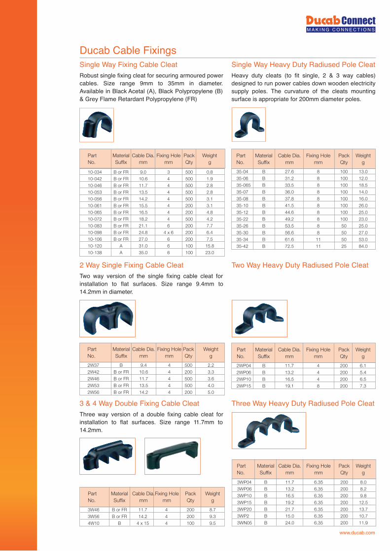
Ducab Cable FixingsSingle Way Fixing Cable CleatRobust single fixing cleat for securing armoured power cables. Size range 9mm to 35mm in diameter. Available in Black Acetal (A), Black Polypropylene (B) & Grey Flame Retardant Polypropylene (FR)
Single Way Heavy Duty Radiused Pole CleatHeavy duty cleats (to fit single, 2 & 3 way cables) designed to run power cables down wooden electricity supply poles. The curvature of the cleats mounting surface is appropriate for 200mm diameter poles.
2 Way Single Fixing Cable CleatTwo way version of the single fixing cable cleat for installation to flat surfaces. Size range 9.4mm to 14.2mm in diameter.
Two Way Heavy Duty Radiused Pole Cleat
10-034 B or FR 9.0 3 500 0.8
10-042 B or FR 10.6 4 500 1.9
10-046 B or FR 11.7 4 500 2.8
10-053 B or FR 13.5 4 500 2.8
10-056 B or FR 14.2 4 500 3.1
10-061 B or FR 15.5 4 200 3.1
10-065 B or FR 16.5 4 200 4.8
10-072 B or FR 18.2 4 500 4.2
10-083 B or FR 21.1 6 200 7.7
10-098 B or FR 24.8 4 x 6 200 6.4
10-106 B or FR 27.0 6 200 7.5
10-120 A 31.0 6 100 15.8
10-138 A 35.0 6 100 23.0
Part Material Cable Dia. Fixing Hole Pack Weight No. Suffix mm mm Qty g
35-04 B 27.6 8 100 13.0
35-06 B 31.2 8 100 12.0
35-065 B 33.5 8 100 18.5
35-07 B 36.0 8 100 14.0
35-08 B 37.8 8 100 16.0
35-10 B 41.5 8 100 26.0
35-12 B 44.6 8 100 25.0
35-22 B 49.2 8 100 23.0
35-26 B 53.5 8 50 25.0
35-30 B 56.6 8 50 27.0
35-34 B 61.6 11 50 53.0
35-42 B 72.5 11 25 84.0
Part Material Cable Dia. Fixing Hole Pack WeightNo. Suffix mm mm Qty g
2W37 B 9.4 4 500 2.2
2W42 B or FR 10.6 4 200 3.3
2W46 B or FR 11.7 4 500 3.6
2W53 B or FR 13.5 4 500 4.0
2W56 B or FR 14.2 4 200 5.0
Part Material Cable Dia. Fixing Hole Pack WeightNo. Suffix mm mm Qty g
2WP04 B 11.7 4 200 6.1
2WP06 B 13.2 4 200 5.4
2WP10 B 16.5 4 200 6.5
2WP15 B 19.1 8 200 7.3
Part Material Cable Dia. Fixing Hole Pack WeightNo. Suffix mm mm Qty g
3 & 4 Way Double Fixing Cable CleatThree way version of a double fixing cable cleat for installation to flat surfaces. Size range 11.7mm to 14.2mm.
Three Way Heavy Duty Radiused Pole Cleat
3WP04 B 11.7 6.35 200 8.0
3WP06 B 13.2 6.35 200 8.2
3WP10 B 16.5 6.35 200 9.8
3WP15 B 19.2 6.35 200 12.5
3WP20 B 21.7 6.35 200 13.7
3WP2 B 15.0 6.35 200 10.7
3WN05 B 24.0 6.35 200 11.9
Part Material Cable Dia. Fixing Hole Pack WeightNo. Suffix mm mm Qty g
3W46 B or FR 11.7 4 200 8.7
3W56 B or FR 14.2 4 200 9.3
4W10 B 4 x 15 4 100 9.5
Part Material Cable Dia.Fixing Hole Pack WeightNo. Suffix mm mm Qty g
www.ducab.com
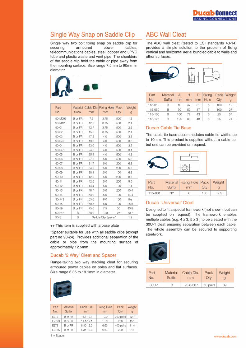
Single Way Snap on Saddle ClipSingle way two bolt fixing snap on saddle clip for securing armoured power cables, telecommunications cables, steel, copper and uPVC tube and plastic waste and vent pipe. The shoulders of the saddle clip hold the cable or pipe away from the mounting surface. Size range 7.5mm to 90mm in diameter.
Ducab ‘2 Way’ Cleat and SpacerRange-taking two way stacking cleat for securing armoured power cables on poles and flat surfaces. Size range 6.35 to 19.1mm in diameter.
Ducab Cable Tie BaseThe cable tie base accommodates cable tie widths up to 10mm. This product is supplied without a cable tie, but one can be provided on request.
Ducab ‘Universal’ CleatDesigned to fit a special framework (not shown, but can be supplied on request). The framework enables multiple cables (e.g. 4 x 3, 5 x 3 ) to be cleated with the 30U-1 cleat ensuring separation between each cable. The whole assembly can be secured to supporting steelwork.
++ This item is supplied with a base plate*Spacer suitable for use with all saddle clips (except part no 90-24). Provides additional separation of the cable or pipe from the mounting surface of approximately 12.5mm.
ABC Wall CleatThe ABC wall cleat (tested to ESI standards 43-14) provides a simple solution to the problem of fixing vertical and horizontal aerial bundled cable to walls and other surfaces.
90-M095 B or FR 7.5 3.75 500 1.8
90-M120 B or FR 12.0 3.75 500 2.4
90-01 B or FR 12.7 3.75 500 2.2
90-02 B or FR 15.0 3.75 500 2.4
90-03 B or FR 17.5 4.0 500 3.3
90-075 B or FR 19.0 4.0 500 3.6
90-04 B or FR 23.0 4.0 500 3.2
90-04.1 B or FR 24.2 4.0 500 3.1
90-05 B or FR 25.4 4.0 500 4.3
90-06 B or FR 27.5 5.0 500 5.3
90-07 B or FR 31.7 5.0 200 6.8
90-08 B or FR 34.0 5.0 200 6.7
90-09 B or FR 38.1 5.0 100 6.8
90-10 B or FR 42.0 5.0 200 8.7
90-11 B or FR 42.6 5.0 200 9.5
90-12 B or FR 44.4 5.0 100 7.4
90-13 B or FR 48.7 5.0 200 10.4
90-14 B or FR 53.9 5.0 100 14.4
90-143 B or FR 55.0 6.0 100 tba
90-15 B or FR 60.5 6.0 100 25.8
90-19 B or FR 75.0 7.5 50 40.8
90-24++ B 88.9 10.0 25 70.7
90-S B Saddle Clip Spacer* 1.2
Part Material Cable Dia. Fixing Hole Pack WeightNo. Suffix mm mm Qty g
S = Spacer
E272 B or FR 11.1-19.1 10.0 200 pairs 22.7
E272S B or FR 11.1-19.1 10.0 200 15.1
E273 B or FR 6.35-12.0 6.63 400 pairs 11.4
E273S B or FR 6.35-12.0 6.63 200 7.2
Part Material Cable Dia. Fixing Hole Pack Weight No. Suffix mm mm Qty g
H
D A
115-010 B 10 47 31 6 100 12
115-050 B 50 59 37 6 100 27
115-100 B 100 72 43 6 25 54
115-125 B 125 80 48 6 25 74
Part Material A H D Fixing Pack WeightNo. Suffix mm mm mm Hole Qty g
115-001 NY 6 100 2.5
Part Material Fixing Hole Pack WeightNo. Suffix mm Qty g
30U-1 B 23.8-38.1 50 pairs 89
Part Material Cable Dia. Pack WeightNo. Suffix mm Qty g
www.ducab.com
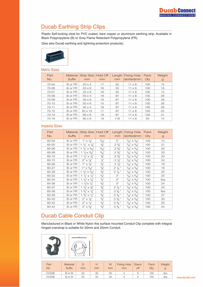
Ducab Earthing Strip Clips
Metric Sizes
Ducab Cable Conduit Clip
Plastic Self-locking cleat for PVC coated, bare copper or aluminium earthing strip. Available in Black Polypropylene (B) or Grey Flame Retardant Polypropylene (FR).(See also Ducab earthing and lightning protection products).
Manufactured in Black or White Nylon this surface mounted Conduit Clip complete with integral hinged overstrap is suitable for 20mm and 25mm Conduit.
Part Material Strip Size Hold Off Length Fixing Hole Pack Weight No. Suffix mm mm mm (slotted)mm Qty g
70-04 B or FR 20 x 4 17 55 11 x 8 100 15
70-06 B or FR 20 x 6 16 55 11 x 8 100 16
70-07 B or FR 25 x 6 16 55 11 x 8 100 14
70-08 B or FR 50 x 4 18 87 11 x 8 100 28
70-09 B or FR 40 x 6 16 87 11 x 8 100 28
70-10 B or FR 50 x 6 15 87 11 x 8 100 26
70-11 B or FR 40 x 4 18 87 11 x 8 100 28
70-12 B or FR 50 x 10 11 87 11 x 8 100 24
70-14 B or FR 60 x 6 18 97 11 x 8 100 31
70-16 B or FR 80 x 6 19 118 11 x 8 50 15
Imperial SizesPart Material Strip Size Hold Off Length Fixing Hole Pack WeightNo. Suffix mm mm mm (slotted)mm Qty g
60-04 B or FR 1” x 1/8” 5/16” 2” 7/16” x 5/16” 100 12
60-05 B or FR 1 1/4” x 1/8” 3/8” 2 5/8” 7/16” x 5/16” 100 21
60-06 B or FR 1 1/4” x 3/16” 5/16” 2 5/8” 7/16” x 5/16” 100 20
60-08 B or FR 1 1/2 x 3/16” 5/16” 2 5/8” 7/16” x 5/16” 100 20
60-10 B or FR 1 1/2” x 1/8” 3/8” 2 5/8” 7/16” x 5/16” 100 20
60-15 B or FR 2” x 1/8” 1/4” 3 1/8” 7/16” x 5/16” 100 24
60-26 B or FR 1” x 1/8” 3/4” 2 1/8” 7/16” x 5/16” 100 16
60-27 B or FR 1” x 3/16” 5/8” 2 1/8 ” 7/16” x 5/16” 100 16
60-28 B or FR 1 1/2” x 3/16” 5/8” 2 7/8 ” 7/16” x 5/16” 100 25
60-32 B or FR 1 1/4” x 1/4” 5/8” 3” 7/16” x 5/16” 100 25
60-34 B or FR 1 1/2” x 1/8” 3/4” 3” 7/16” x 5/16” 100 tba
60-36 B or FR 1 1/2”x 1/4” 5/8” 3” 7/16” x 5/16” 100 24
60-37 B or FR 1 1/2” x 3/8” 3/8” 2 7/8 ” 7/16” x 5/16” 100 23
60-38 B or FR 1 3/4” x 1/8” 3/4” 3 3/8 ” 7/16” x 5/16” 100 tba
60-39 B or FR 1 3/4” x 1/4” 5/8” 3 3/8 ” 7/16” x 5/16” 100 27
60-40 B or FR 2” x 1/8” 3/4” 3 3/8 ” 7/16” x 5/16” 100 30
60-42 B or FR 2” x 1/4” 5/8” 3 3/8 ” 7/16” x 5/16” 100 25
60-44 B or FR 2” x 3/8” 3/8” 3 3/8 ” 7/16” x 5/16” 100 24
Part Material D H W Fixing Hole Stand Pack WeightNo Suffix mm mm mm mm off Qty g
CC20B B or W 20 35 35 4 5 100 tba
CC25B B or W 25 40 40 4 5 100 tba
W
HD
www.ducab.com
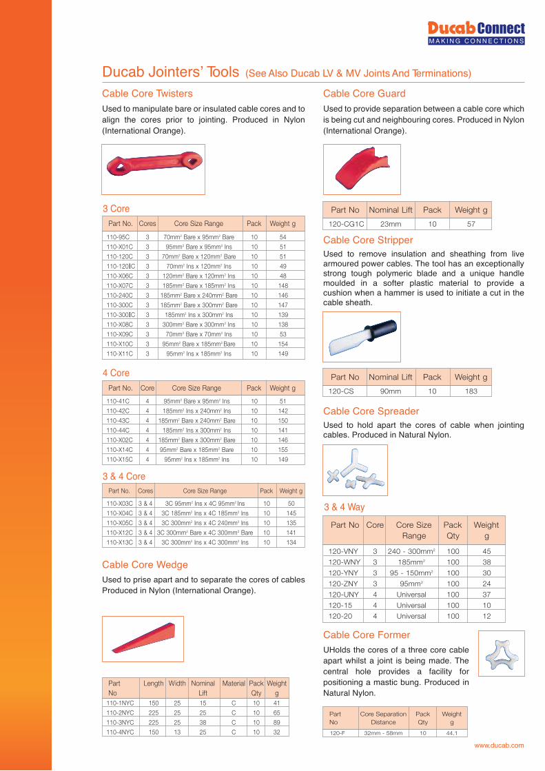
Ducab Jointers’ Tools (See Also Ducab LV & MV Joints And Terminations)
Cable Core TwistersUsed to manipulate bare or insulated cable cores and to align the cores prior to jointing. Produced in Nylon (International Orange).
Cable Core WedgeUsed to prise apart and to separate the cores of cables Produced in Nylon (International Orange).
Cable Core GuardUsed to provide separation between a cable core which is being cut and neighbouring cores. Produced in Nylon (International Orange).
Cable Core StripperUsed to remove insulation and sheathing from live armoured power cables. The tool has an exceptionally strong tough polymeric blade and a unique handle moulded in a softer plastic material to provide a cushion when a hammer is used to initiate a cut in the cable sheath.
Cable Core SpreaderUsed to hold apart the cores of cable when jointing cables. Produced in Natural Nylon.
Cable Core FormerUHolds the cores of a three core cable apart whilst a joint is being made. The central hole provides a facility for positioning a mastic bung. Produced in Natural Nylon.
110-1NYC 150 25 15 C 10 41
110-2NYC 225 25 25 C 10 65
110-3NYC 225 25 38 C 10 89
110-4NYC 150 13 25 C 10 32
Part Length Width Nominal Material Pack Weight gytQtfiLoN
110-X03C 3 & 4 3C 95mm2 Ins x 4C 95mm2 Ins 10 50
110-X04C 3 & 4 3C 185mm2 Ins x 4C 185mm2 Ins 10 145
110-X05C 3 & 4 3C 300mm2 Ins x 4C 240mm2 Ins 10 135
110-X12C 3 & 4 3C 300mm2 Bare x 4C 300mm2 Bare 10 141
110-X13C 3 & 4 3C 300mm2 Ins x 4C 300mm2 Ins 10 134
Part No. Cores Core Size Range Pack Weight g
110-41C 4 95mm2 Bare x 95mm2 Ins 10 51
110-42C 4 185mm2 Ins x 240mm2 Ins 10 142
110-43C 4 185mm2 Bare x 240mm2 Bare 10 150
110-44C 4 185mm2 Ins x 300mm2 Ins 10 141
110-X02C 4 185mm2 Bare x 300mm2 Bare 10 146
110-X14C 4 95mm2 Bare x 185mm2 Bare 10 155
110-X15C 4 95mm2 Ins x 185mm2 Ins 10 149
Part No. Core Core Size Range Pack Weight g
110-95C 3 70mm2 Bare x 95mm2 Bare 10 54
110-X01C 3 95mm2 Bare x 95mm2 Ins 10 51
110-120C 3 70mm2 Bare x 120mm2 Bare 10 51
110-120IC 3 70mm2 Ins x 120mm2 Ins 10 49
110-X06C 3 120mm2 Bare x 120mm2 Ins 10 48
110-X07C 3 185mm2 Bare x 185mm2 Ins 10 148
110-240C 3 185mm2 Bare x 240mm2 Bare 10 146
110-300C 3 185mm2 Bare x 300mm2 Bare 10 147
110-300IC 3 185mm2 Ins x 300mm2 Ins 10 139
110-X08C 3 300mm2 Bare x 300mm2 Ins 10 138
110-X09C 3 70mm2 Bare x 70mm2 Ins 10 53
110-X10C 3 95mm2 Bare x 185mm2 Bare 10 154
110-X11C 3 95mm2 Ins x 185mm2 Ins 10 149
Part No. Cores Core Size Range Pack Weight g
3 & 4 Core
3 & 4 Way
4 Core
3 Core120-CG1C 23mm 10 57
Part No Nominal Lift Pack Weight g
120-CS 90mm 10 183
Part No Nominal Lift Pack Weight g
120-VNY 3 240 - 300mm2 100 45
120-WNY 3 185mm2 100 38
120-YNY 3 95 - 150mm2 100 30
120-ZNY 3 95mm2 100 24
120-UNY 4 Universal 100 37
120-15 4 Universal 100 10
120-20 4 Universal 100 12
Part No Core Core Size Pack WeightRange Qty g
120-F 32mm - 58mm 10 44.1
Part Core Separation Pack WeightNo Distance Qty g
www.ducab.com
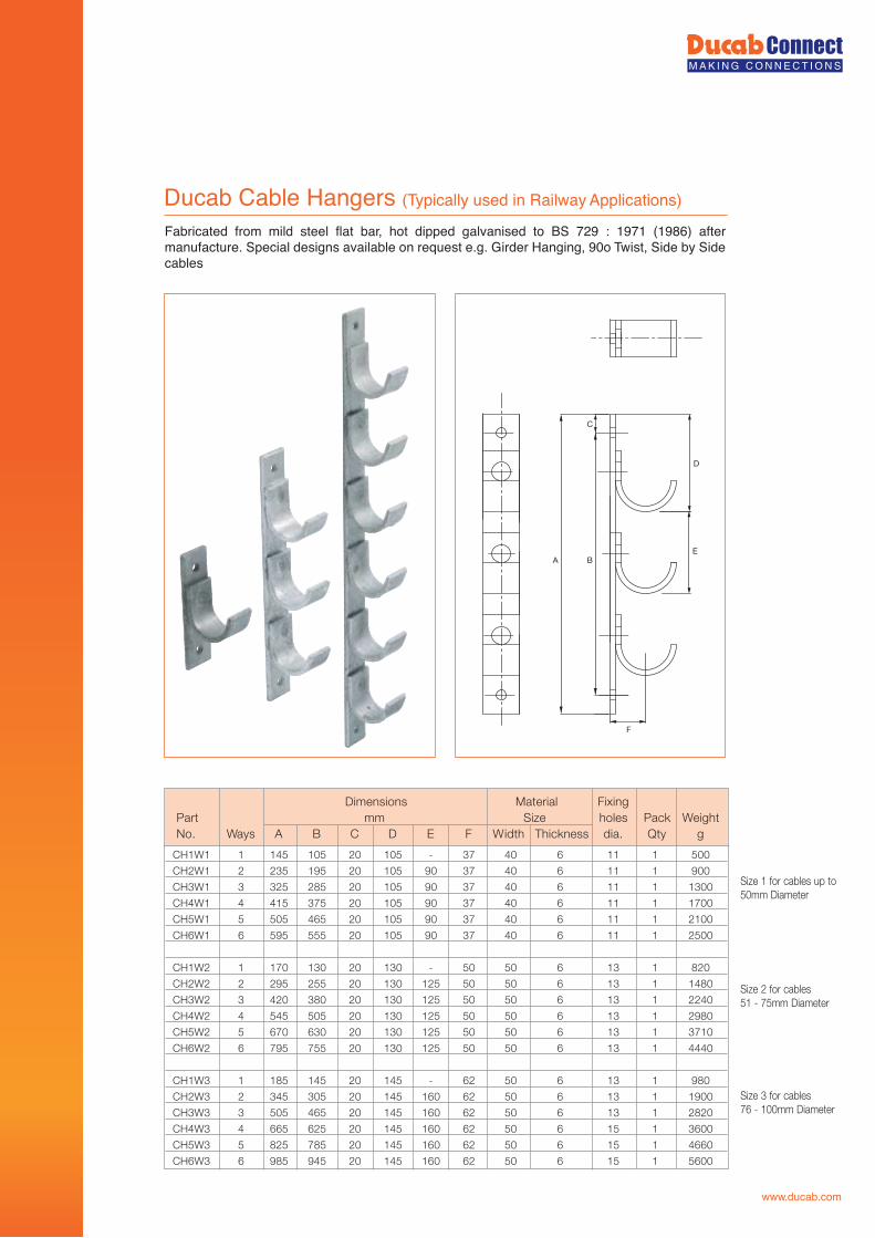
Ducab Cable Hangers (Typically used in Railway Applications)
Fabricated from mild steel flat bar, hot dipped galvanised to BS 729 : 1971 (1986) after manufacture. Special designs available on request e.g. Girder Hanging, 90o Twist, Side by Side cables
Size 1 for cables up to 50mm Diameter
Size 2 for cables51 - 75mm Diameter
Size 3 for cables 76 - 100mm Diameter
D
BA
C
E
F
Dimensions Material FixingthgieW kcaPseloheziSmmtraP
No. Ways A B C D E F Width Thickness dia. Qty g
CH1W1 1 145 105 20 105 - 37 40 6 11 1 500
CH2W1 2 235 195 20 105 90 37 40 6 11 1 900
CH3W1 3 325 285 20 105 90 37 40 6 11 1 1300
CH4W1 4 415 375 20 105 90 37 40 6 11 1 1700
CH5W1 5 505 465 20 105 90 37 40 6 11 1 2100
CH6W1 6 595 555 20 105 90 37 40 6 11 1 2500
CH1W2 1 170 130 20 130 - 50 50 6 13 1 820
CH2W2 2 295 255 20 130 125 50 50 6 13 1 1480
CH3W2 3 420 380 20 130 125 50 50 6 13 1 2240
CH4W2 4 545 505 20 130 125 50 50 6 13 1 2980
CH5W2 5 670 630 20 130 125 50 50 6 13 1 3710
CH6W2 6 795 755 20 130 125 50 50 6 13 1 4440
CH1W3 1 185 145 20 145 - 62 50 6 13 1 980
CH2W3 2 345 305 20 145 160 62 50 6 13 1 1900
CH3W3 3 505 465 20 145 160 62 50 6 13 1 2820
CH4W3 4 665 625 20 145 160 62 50 6 15 1 3600
CH5W3 5 825 785 20 145 160 62 50 6 15 1 4660
CH6W3 6 985 945 20 145 160 62 50 6 15 1 5600
www.ducab.com
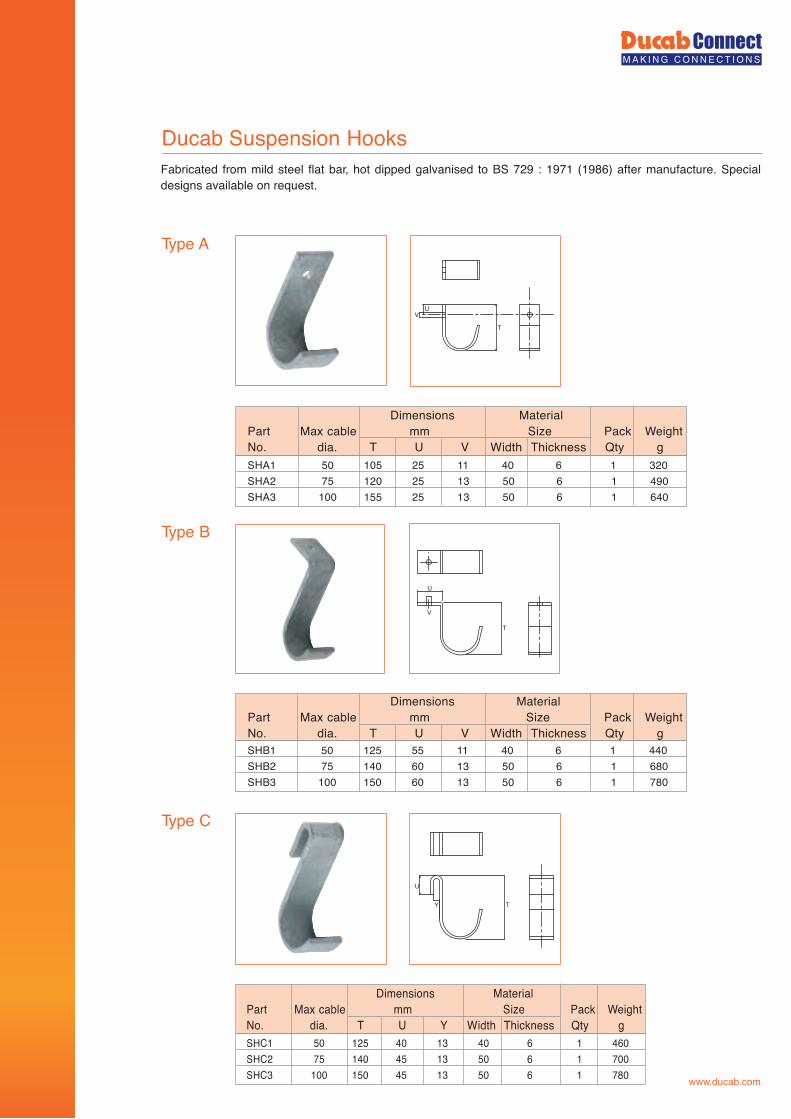
Dimensions MaterialPart Max cable mm Size Pack WeightNo. dia. T U V Width Thickness Qty g
Dimensions MaterialPart Max cable mm Size Pack WeightNo. dia. T U V Width Thickness Qty g
Dimensions MaterialPart Max cable mm Size Pack WeightNo. dia. T U Y Width Thickness Qty g
Ducab Suspension Hooks
Type A
Type B
Type C
SHA1 50 105 25 11 40 6 1 320SHA2 75 120 25 13 50 6 1 490SHA3 100 155 25 13 50 6 1 640
SHB1 50 125 55 11 40 6 1 440SHB2 75 140 60 13 50 6 1 680SHB3 100 150 60 13 50 6 1 780
SHC1 50 125 40 13 40 6 1 460SHC2 75 140 45 13 50 6 1 700SHC3 100 150 45 13 50 6 1 780
V
T
U
T
U
V
T
U
Y
Fabricated from mild steel flat bar, hot dipped galvanised to BS 729 : 1971 (1986) after manufacture. Special designs available on request.
www.ducab.com
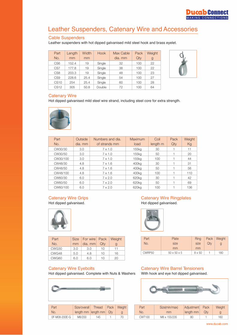
Leather Suspenders, Catenary Wire and Accessories
Leather suspenders with hot dipped galvanised mild steel hook and brass eyelet.Cable Suspenders
Hot dipped galvanised mild steel wire strand, including steel core for extra strength.Catenary Wire
Hot dipped galvanised.Catenary Wire Grips
CS6 152.4 19 Single 32 100 22
CS7 177.8 19 Single 38 100 22
CS8 203.3 19 Single 48 100 23
CS9 228.6 25.4 Single 54 100 27
CS10 254 25.4 Single 60 100 28
CS12 305 50.8 Double 72 100 64
Part Length Width Hook Max Cable Pack WeightNo. mm mm dia. mm Qty g
CW30/30 3.0 7 x 1.0 155kg 30 1 11
CW30/50 3.0 7 x 1.0 155kg 50 1 20
CW30/100 3.0 7 x 1.0 155kg 100 1 44
CW48/30 4.8 7 x 1.6 400kg 30 1 31
CW48/50 4.8 7 x 1.6 400kg 50 1 56
CW48/100 4.8 7 x 1.6 400kg 100 1 110
CW60/30 6.0 7 x 2.0 620kg 30 1 42
CW60/50 6.0 7 x 2.0 620kg 50 1 69
CW60/100 6.0 7 x 2.0 620kg 100 1 136
Part Outside Numbers and dia. Maximum Coil Pack WeightNo. dia. mm of strands mm load length m Qty Kg
Hot dipped galvanised.Catenary Wire Ringplates
Hot dipped galvanised. Complete with Nuts & WashersCatenary Wire Eyebolts
With hook and eye hot dipped galvanised.Catenary Wire Barrel Tensioners
CWG30 3.0 3.0 10 11
CWG48 5.0 4.8 10 16
CWG60 6.0 6.0 10 20
Part Size For wire Pack WeightNo. mm dia. mm Qty g
CWRP50 50 x 50 x 5 8 x 50 1 180
Part Plate Ring Pack WeightNo. size size Qty g
mm mm
CWT100 M8 x 155/235 80 1 160
Part Size(min/max) Adjustment Pack WeightNo. mm length mm Qty g
0F-M08-200E-G M8/200 145 1 70
Part Size/overall Thread Pack WeightNo. length mm length mm Qty g
www.ducab.com
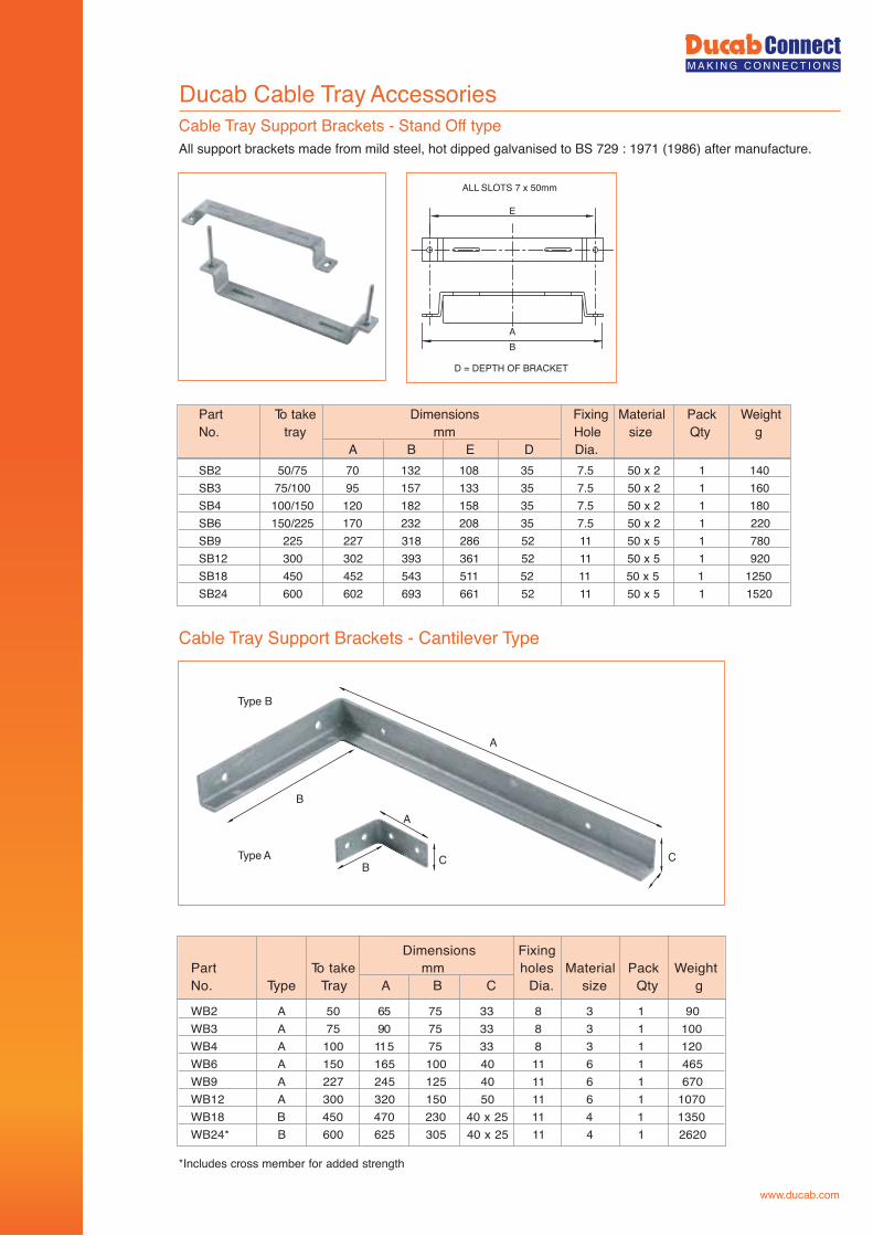
Part To take Dimensions Fixing Material Pack WeightNo. tray mm Hole size Qty g
A B E D Dia.SB2 50/75 70 132 108 35 7.5 50 x 2 1 140SB3 75/100 95 157 133 35 7.5 50 x 2 1 160SB4 100/150 120 182 158 35 7.5 50 x 2 1 180SB6 150/225 170 232 208 35 7.5 50 x 2 1 220SB9 225 227 318 286 52 11 50 x 5 1 780SB12 300 302 393 361 52 11 50 x 5 1 920SB18 450 452 543 511 52 11 50 x 5 1 1250SB24 600 602 693 661 52 11 50 x 5 1 1520
Dimensions FixingPart To take mm holes Material Pack WeightNo. Type Tray A B C Dia. size Qty g
Ducab Cable Tray Accessories
All support brackets made from mild steel, hot dipped galvanised to BS 729 : 1971 (1986) after manufacture.
*Includes cross member for added strength
Cable Tray Support Brackets - Stand Off type
Cable Tray Support Brackets - Cantilever Type
WB2 A 50 65 75 33 8 3 1 90WB3 A 75 90 75 33 8 3 1 100WB4 A 100 115 75 33 8 3 1 120WB6 A 150 165 100 40 11 6 1 465WB9 A 227 245 125 40 11 6 1 670WB12 A 300 320 150 50 11 6 1 1070WB18 B 450 470 230 40 x 25 11 4 1 1350WB24* B 600 625 305 40 x 25 11 4 1 2620
Type A
Type B
A
B
B C C
A
D = DEPTH OF BRACKET
ALL SLOTS 7 x 50mm
E
AB
www.ducab.com
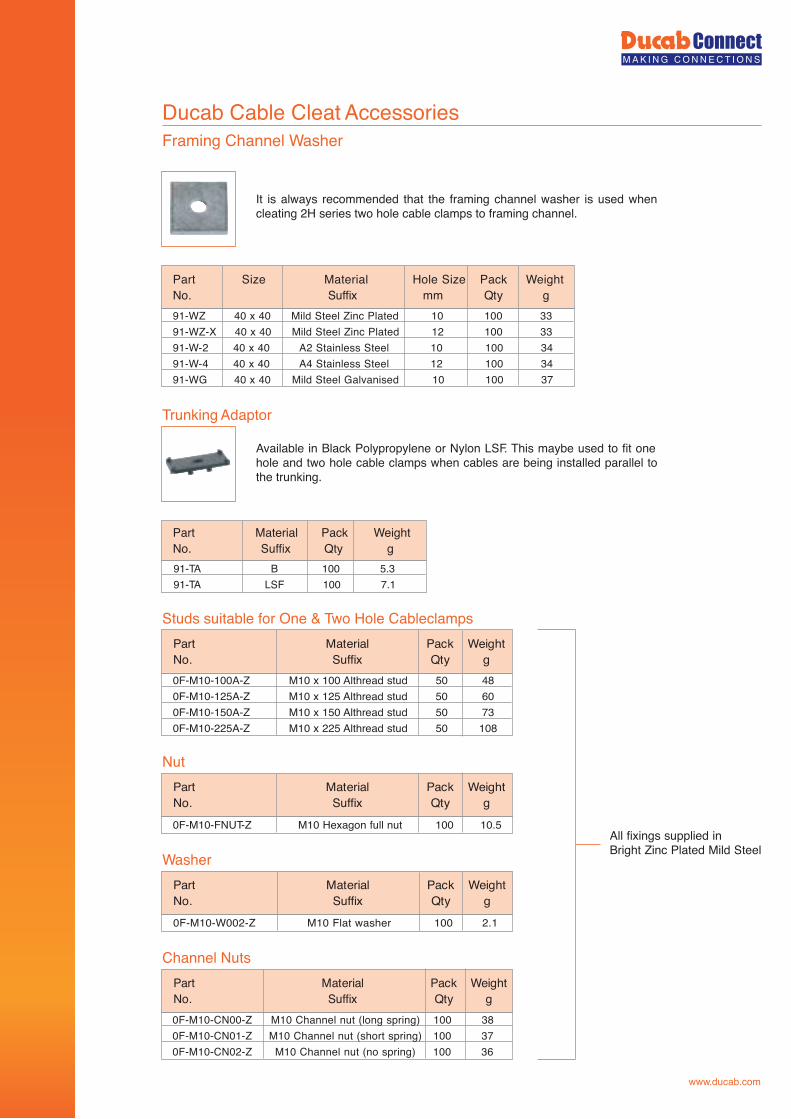
All fixings supplied in Bright Zinc Plated Mild Steel
Ducab Cable Cleat AccessoriesFraming Channel Washer
Trunking Adaptor
Studs suitable for One & Two Hole Cableclamps
Nut
Washer
Channel Nuts
91-WZ 40 x 40 Mild Steel Zinc Plated 10 100 3391-WZ-X 40 x 40 Mild Steel Zinc Plated 12 100 3391-W-2 40 x 40 A2 Stainless Steel 10 100 3491-W-4 40 x 40 A4 Stainless Steel 12 100 3491-WG 40 x 40 Mild Steel Galvanised 10 100 37
91-TA B 100 5.391-TA LSF 100 7.1
Part Material Pack WeightNo. Suffix Qty g
Part Size Material Hole Size Pack WeightgytQmmxiffuS.oN
0F-M10-FNUT-Z M10 Hexagon full nut 100 10.5
thgieWkcaPlairetaM traPgytQxiffuS.oN
0F-M10-W002-Z M10 Flat washer 100 2.1
thgieWkcaPlairetaM traPgytQxiffuS.oN
0F-M10-100A-Z M10 x 100 Althread stud 50 480F-M10-125A-Z M10 x 125 Althread stud 50 600F-M10-150A-Z M10 x 150 Althread stud 50 730F-M10-225A-Z M10 x 225 Althread stud 50 108
thgieWkcaPlairetaM traPgytQxiffuS.oN
0F-M10-CN00-Z M10 Channel nut (long spring) 100 380F-M10-CN01-Z M10 Channel nut (short spring) 100 370F-M10-CN02-Z M10 Channel nut (no spring) 100 36
thgieWkcaPlairetaM traPgytQxiffuS.oN
It is always recommended that the framing channel washer is used when cleating 2H series two hole cable clamps to framing channel.
Available in Black Polypropylene or Nylon LSF. This maybe used to fit one hole and two hole cable clamps when cables are being installed parallel to the trunking.
www.ducab.com
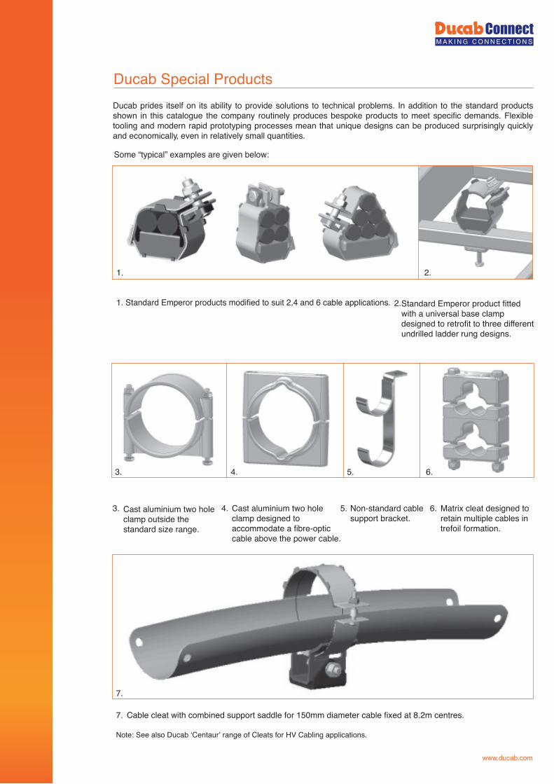
Some “typical” examples are given below:
1. Standard Emperor products modified to suit 2,4 and 6 cable applications.
1.
2.
3. 4. 5. 6.
7. Cable cleat with combined support saddle for 150mm diameter cable fixed at 8.2m centres.
Note: See also Ducab ‘Centaur’ range of Cleats for HV Cabling applications.
Ducab prides itself on its ability to provide solutions to technical problems. In addition to the standard products shown in this catalogue the company routinely produces bespoke products to meet specific demands. Flexible tooling and modern rapid prototyping processes mean that unique designs can be produced surprisingly quickly and economically, even in relatively small quantities.
Standard Emperor product fittedwith a universal base clamp designed to retrofit to three different undrilled ladder rung designs.
Cast aluminium two hole clamp outside the standard size range.
Cast aluminium two hole clamp designed to accommodate a fibre-optic cable above the power cable.
Non-standard cablesupport bracket.
Matrix cleat designed to retain multiple cables in trefoil formation.
www.ducab.com
Ducab Special Products
2.
3. 4. 5. 6.
7.
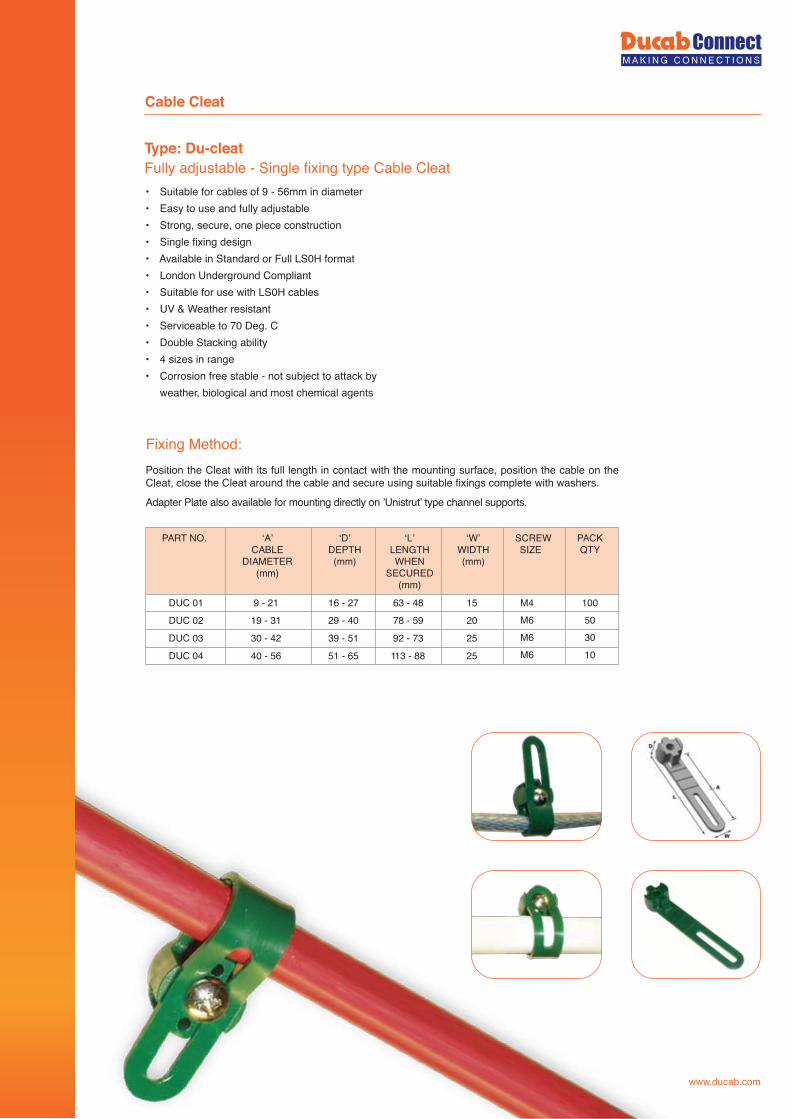
Fixing Method:
• Suitable for cables of 9 - 56mm in diameter• Easy to use and fully adjustable• Strong, secure, one piece construction• Single fixing design• Available in Standard or Full LS0H format• London Underground Compliant• Suitable for use with LS0H cables• UV & Weather resistant• Serviceable to 70 Deg. C• Double Stacking ability• 4 sizes in range• Corrosion free stable - not subject to attack by weather, biological and most chemical agents
Type: Du-cleatFully adjustable - Single fixing type Cable Cleat
DUC 01 9 - 21 16 - 27 63 - 48 15 M4M6M6M6
100503010
DUC 02 19 - 31 29 - 40 78 - 59 20
DUC 03 30 - 42 39 - 51 92 - 73 25
DUC 04 40 - 56 51 - 65 113 - 88 25
PART NO. ‘A’CABLE
DIAMETER(mm)
‘D’DEPTH(mm)
‘L’LENGTHWHEN
SECURED(mm)
‘W’WIDTH(mm)
SCREWSIZE
PACKQTY
Position the Cleat with its full length in contact with the mounting surface, position the cable on the Cleat, close the Cleat around the cable and secure using suitable fixings complete with washers.
Adapter Plate also available for mounting directly on ’Unistrut’ type channel supports.
Cable Cleat
www.ducab.com
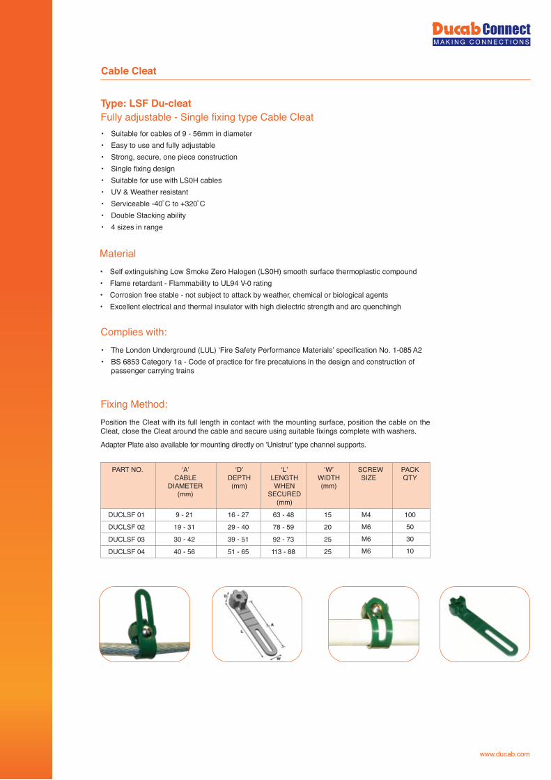
Fixing Method:
• Suitable for cables of 9 - 56mm in diameter• Easy to use and fully adjustable• Strong, secure, one piece construction• Single fixing design• Suitable for use with LS0H cables• UV & Weather resistant• Serviceable -40˚C to +320˚C• Double Stacking ability• 4 sizes in range
Type: LSF Du-cleatFully adjustable - Single fixing type Cable Cleat
DUCLSF 01 9 - 21 16 - 27 63 - 48 15 M4M6M6M6
100503010
DUCLSF 02 19 - 31 29 - 40 78 - 59 20
DUCLSF 03 30 - 42 39 - 51 92 - 73 25
DUCLSF 04 40 - 56 51 - 65 113 - 88 25
PART NO. ‘A’CABLE
DIAMETER(mm)
‘D’DEPTH(mm)
‘L’LENGTHWHEN
SECURED(mm)
‘W’WIDTH(mm)
SCREWSIZE
PACKQTY
Position the Cleat with its full length in contact with the mounting surface, position the cable on the Cleat, close the Cleat around the cable and secure using suitable fixings complete with washers.
Adapter Plate also available for mounting directly on ’Unistrut’ type channel supports.
Material• Self extinguishing Low Smoke Zero Halogen (LS0H) smooth surface thermoplastic compound• Flame retardant - Flammability to UL94 V-0 rating• Corrosion free stable - not subject to attack by weather, chemical or biological agents• Excellent electrical and thermal insulator with high dielectric strength and arc quenchingh
Complies with:• The London Underground (LUL) ‘Fire Safety Performance Materials’ specification No. 1-085 A2• BS 6853 Category 1a - Code of practice for fire precatuions in the design and construction of
passenger carrying trains
Cable Cleat
www.ducab.com
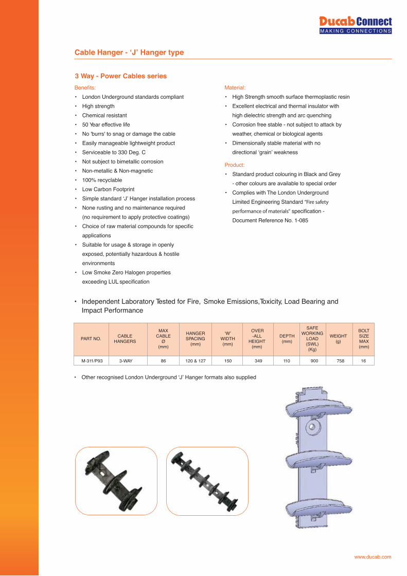
3 Way - Power Cables series
Cable Hanger - ‘J’ Hanger type
Benefits: • London Underground standards compliant • High strength • Chemical resistant • 50 Year effective life • No 'burrs' to snag or damage the cable • Easily manageable lightweight product • Serviceable to 330 Deg. C • Not subject to bimetallic corrosion • Non-metallic & Non-magnetic • 100% recyclable • Low Carbon Footprint • Simple standard ‘J’ Hanger installation process • None rusting and no maintenance required (no requirement to apply protective coatings) • Choice of raw material compounds for specific applications• Suitable for usage & storage in openly exposed, potentially hazardous & hostile environments • Low Smoke Zero Halogen properties exceeding LUL specification
Material: • High Strength smooth surface thermoplastic resin • Excellent electrical and thermal insulator with high dielectric strength and arc quenching • Corrosion free stable - not subject to attack by weather, chemical or biological agents • Dimensionally stable material with no directional ‘grain’ weakness
Product: • Standard product colouring in Black and Grey - other colours are available to special order • Complies with The London Underground Limited Engineering Standard “Fire safety
performance of materials” specification - Document Reference No. 1-085
• Other recognised London Underground ‘J’ Hanger formats also supplied
M-311/P93 3-WAY 86 120 & 127 150 349 110 900 758 16
PART NO. CABLE HANGERS
MAX CABLE
Ø (mm)
HANGER SPACING
(mm)
‘W’WIDTH(mm)
OVER-ALL
HEIGHT (mm)
DEPTH (mm)
SAFE WORKING
LOAD (SWL) (Kg)
WEIGHT (g)
BOLT SIZE MAX (mm)
• Independent Laboratory Tested for Fire, Smoke Emissions,Toxicity, Load Bearing and Impact Performance
www.ducab.com
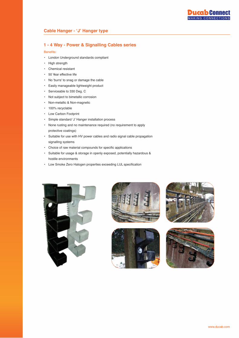
1 - 4 Way - Power & Signalling Cables series
Cable Hanger - ‘J’ Hanger type
Benefits:• London Underground standards compliant• High strength• Chemical resistant• 50 Year effective life• No 'burrs' to snag or damage the cable• Easily manageable lightweight product• Serviceable to 330 Deg. C• Not subject to bimetallic corrosion• Non-metallic & Non-magnetic• 100% recyclable• Low Carbon Footprint• Simple standard ‘J’ Hanger installation process• None rusting and no maintenance required (no requirement to apply protective coatings)• Suitable for use with HV power cables and radio signal cable propagation signalling systems• Choice of raw material compounds for specific applications• Suitable for usage & storage in openly exposed, potentially hazardous & hostile environments• Low Smoke Zero Halogen properties exceeding LUL specification
www.ducab.com
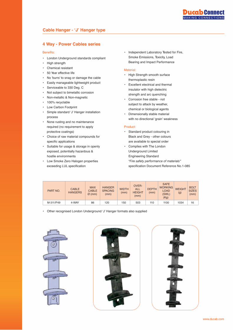
4 Way - Power Cables series
Cable Hanger - ‘J’ Hanger type
Benefits:
• London Underground standards compliant• High strength• Chemical resistant • 50 Year effective life• No 'burrs' to snag or damage the cable• Easily manageable lightweight product• Serviceable to 330 Deg. C• Not subject to bimetallic corrosion• Non-metallic & Non-magnetic• 100% recyclable• Low Carbon Footprint• Simple standard ‘J’ Hanger installation
process• None rusting and no maintenance
required (no requirement to apply protective coatings)
• Choice of raw material compounds for specific applications
• Suitable for usage & storage in openly exposed, potentially hazardous & hostile environments
• Low Smoke Zero Halogen properties exceeding LUL specification
• Independent Laboratory Tested for Fire, Smoke Emissions, Toxicity, Load Bearing and Impact Performance
Material:• High Strength smooth surface
thermoplastic resin• Excellent electrical and thermal
insulator with high dielectric strength and arc quenching
• Corrosion free stable - not subject to attack by weather, chemical or biological agents
• Dimensionally stable material with no directional ‘grain’ weakness
Product:• Standard product colouring in
Black and Grey - other colours are available to special order
• Complies with The London Underground Limited Engineering Standard
“Fire safety performance of materials” specification Document Reference No.1-085
103411001105034-WAY 86 120 150 16
PART NO. CABLEHANGERS
DEPTH(mm)
SAFEWORKING
LOAD(SWL)(Kg)
WEIGHT(g)
BOLTSIZES(mm)
OVER-ALL
HEIGHT(mm)
M-311/P49
MAXCABLEØ (mm)
HANGERSPACING
(mm)
WIDTH(mm)
• Other recognised London Underground ‘J’ Hanger formats also supplied
www.ducab.com
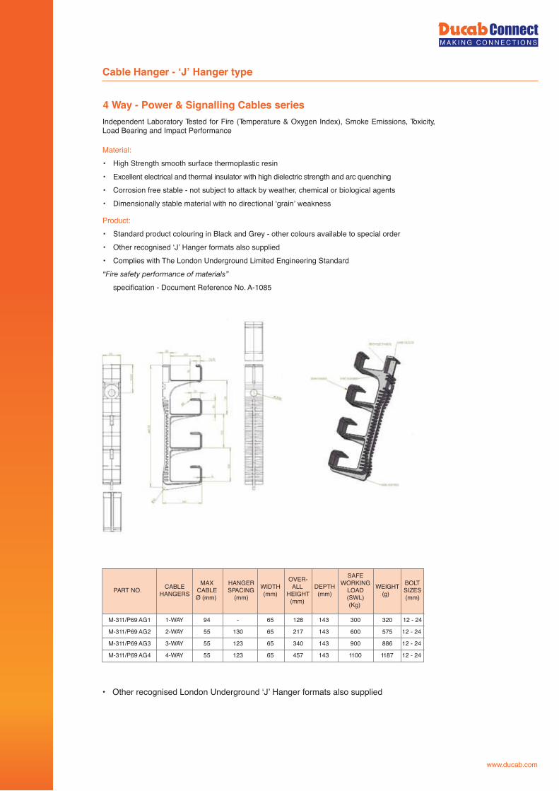
4 Way - Power & Signalling Cables series
• Other recognised London Underground ‘J’ Hanger formats also supplied
320
575
886
1187
300
600
900
1100
143
143
143
143
128
217
340
457
1-WAY
2-WAY
3-WAY
4-WAY
94
55
55
55
-
130
123
123
65
65
65
65
12 - 24
12 - 24
12 - 24
12 - 24
M-311/P69 AG1
M-311/P69 AG2
M-311/P69 AG3
M-311/P69 AG4
PART NO. CABLEHANGERS
DEPTH(mm)
SAFEWORKING
LOAD(SWL)(Kg)
WEIGHT(g)
BOLTSIZES(mm)
OVER-ALL
HEIGHT(mm)
MAXCABLEØ (mm)
HANGERSPACING
(mm)
WIDTH(mm)
Cable Hanger - ‘J’ Hanger type
Independent Laboratory Tested for Fire (Temperature & Oxygen Index), Smoke Emissions, Toxicity, Load Bearing and Impact Performance
Material:• High Strength smooth surface thermoplastic resin• Excellent electrical and thermal insulator with high dielectric strength and arc quenching• Corrosion free stable - not subject to attack by weather, chemical or biological agents• Dimensionally stable material with no directional ‘grain’ weakness
Product:• Standard product colouring in Black and Grey - other colours available to special order• Other recognised ‘J’ Hanger formats also supplied• Complies with The London Underground Limited Engineering Standard “Fire safety performance of materials”
specification - Document Reference No. A-1085
www.ducab.com


www.ducab.com
• Air terminals & fixings• Test & junction clamps• Bonds• Conductor fixings• Conductors, tapes, bars etc.• ESE system (CIRRUS)
Lightning Protection Products & Services
Earthing Products
• Earth rods & fittings• Mechanical clamps• Inspection pits• Copper & lattice earth plates• Earth bonding points• Earth bars & insulators• Miscellaneous
Ducab Connect products are used by specialist Earthing and Lightning protection installers, electrical engineers and Contractors. Our quality range of earthing and lightning protection accessories are suitable for use/specifying to the electricity authorities. Oil, gas and petrochemical sector, Industrial, commercial and civil Construction projects, as well as the telecommunication sector.
Contents
Ducab Earthing & Lightning Protection
www.ducab.com
The following Ducab products are designed and manufactured using the highest quality materials, to enable the capture of the lightning effectively and provide an efficient path down to earth. All our products are of the highest quality and meet stringent recognised International standards.
Lightning Protection
Ducab Earthing & Lightning Protection
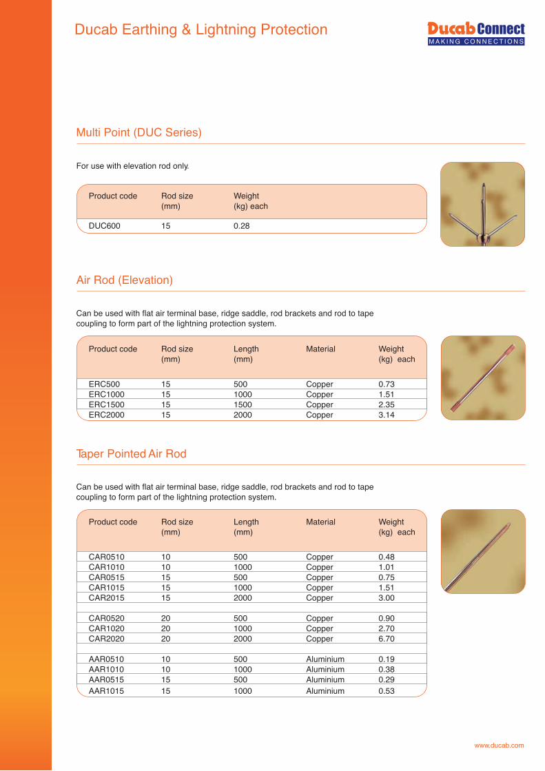
www.ducab.com
Multi Point (DUC Series)
For use with elevation rod only.
Air Rod (Elevation)
Can be used with flat air terminal base, ridge saddle, rod brackets and rod to tape coupling to form part of the lightning protection system.
ERC500 15 500 Copper 0.73 ERC1000 15 1000 Copper 1.51ERC1500 15 1500 Copper 2.35ERC2000 15 2000 Copper 3.14
Taper Pointed Air Rod
Can be used with flat air terminal base, ridge saddle, rod brackets and rod to tape coupling to form part of the lightning protection system.
Product code Rod size Length Material Weight (mm) (mm) (kg) each
CAR0510 10 500 Copper 0.48CAR1010 10 1000 Copper 1.01CAR0515 15 500 Copper 0.75CAR1015 15 1000 Copper 1.51 CAR2015 15 2000 Copper 3.00
CAR0520 20 500 Copper 0.90CAR1020 20 1000 Copper 2.70CAR2020 20 2000 Copper 6.70
AAR0510 10 500 Aluminium 0.19AAR1010 10 1000 Aluminium 0.38AAR0515 15 500 Aluminium 0.29 AAR1015 15 1000 Aluminium 0.53
Product code Rod size Length Material Weight (mm) (mm) (kg) each
DUC600 15 0.28
Product code Rod size Weight (mm) (kg) each
Ducab Earthing & Lightning Protection
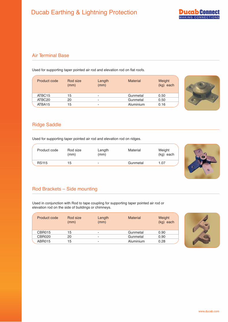
www.ducab.com
Air Terminal Base
Used for supporting taper pointed air rod and elevation rod on flat roofs.
Ridge Saddle
Rod Brackets – Side mounting
Used in conjunction with Rod to tape coupling for supporting taper pointed air rod or elevation rod on the side of buildings or chimneys.
Product code Rod size Length Material Weight (mm) (mm) (kg) each
CBR015 15 - Gunmetal 0.90CBR020 20 - Gunmetal 0.90ABR015 15 - Aluminium 0.28
Used for supporting taper pointed air rod and elevation rod on ridges.
ATBC15 15 - Gunmetal 0.50ATBC20 20 - Gunmetal 0.50ATBA15 15 - Aluminium 0.16
Product code Rod size Length Material Weight (mm) (mm) (kg) each
RS115 15 - Gunmetal 1.07
Product code Rod size Length Material Weight (mm) (mm) (kg) each
Ducab Earthing & Lightning Protection
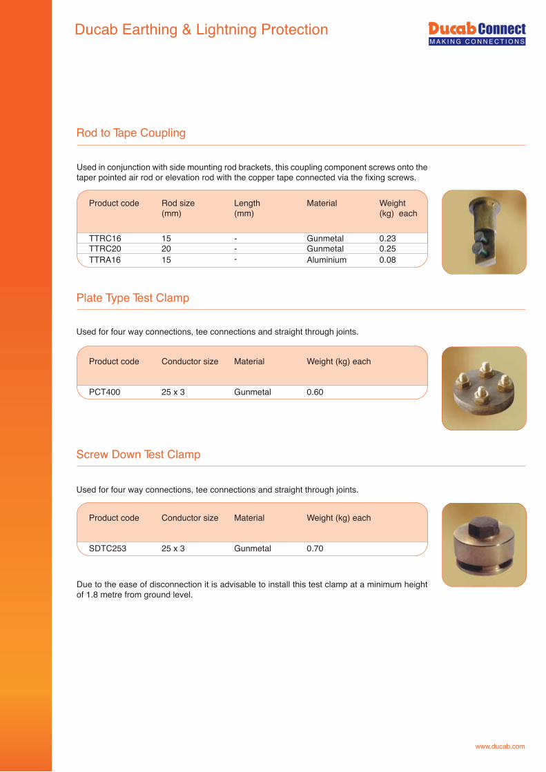
Rod to Tape Coupling
Plate Type Test Clamp
TTRC16 15 - Gunmetal 0.23TTRC20 20 - Gunmetal 0.25 TTRA16 15 - Aluminium 0.08
Product code Rod size Length Material Weight (mm) (mm) (kg) each
Used for four way connections, tee connections and straight through joints.
PCT400 25 x 3 Gunmetal 0.60
Product code Conductor size Material Weight (kg) each
Screw Down Test Clamp
Used for four way connections, tee connections and straight through joints.
SDTC253 25 x 3 Gunmetal 0.70
Product code Conductor size Material Weight (kg) each
Due to the ease of disconnection it is advisable to install this test clamp at a minimum height of 1.8 metre from ground level.
www.ducab.com
Used in conjunction with side mounting rod brackets, this coupling component screws onto the taper pointed air rod or elevation rod with the copper tape connected via the fixing screws.
Ducab Earthing & Lightning Protection
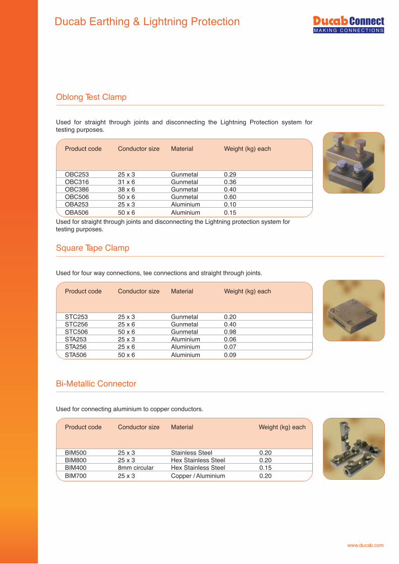
Oblong Test Clamp
Used for straight through joints and disconnecting the Lightning protection system fortesting purposes.
Square Tape Clamp
Bi-Metallic Connector
Used for connecting aluminium to copper conductors.
Product code Conductor size Material Weight (kg) each
BIM500 25 x 3 Stainless Steel 0.20BIM800 25 x 3 Hex Stainless Steel 0.20BIM400 8mm circular Hex Stainless Steel 0.15BIM700 25 x 3 Copper / Aluminium 0.20
OBC253 25 x 3 Gunmetal 0.29OBC316 31 x 6 Gunmetal 0.36OBC386 38 x 6 Gunmetal 0.40OBC506 50 x 6 Gunmetal 0.60OBA253 25 x 3 Aluminium 0.10OBA506 50 x 6 Aluminium 0.15
Product code Conductor size Material Weight (kg) each
Used for four way connections, tee connections and straight through joints.
Product code Conductor size Material Weight (kg) each
STC253 25 x 3 Gunmetal 0.20STC256 25 x 6 Gunmetal 0.40STC506 50 x 6 Gunmetal 0.98STA253 25 x 3 Aluminium 0.06STA256 25 x 6 Aluminium 0.07STA506 50 x 6 Aluminium 0.09
www.ducab.com
Ducab Earthing & Lightning Protection
rof metsys noitcetorP gninthgiL eht gnitcennocsid dna stnioj hguorht thgiarts rof desUtesting purposes.
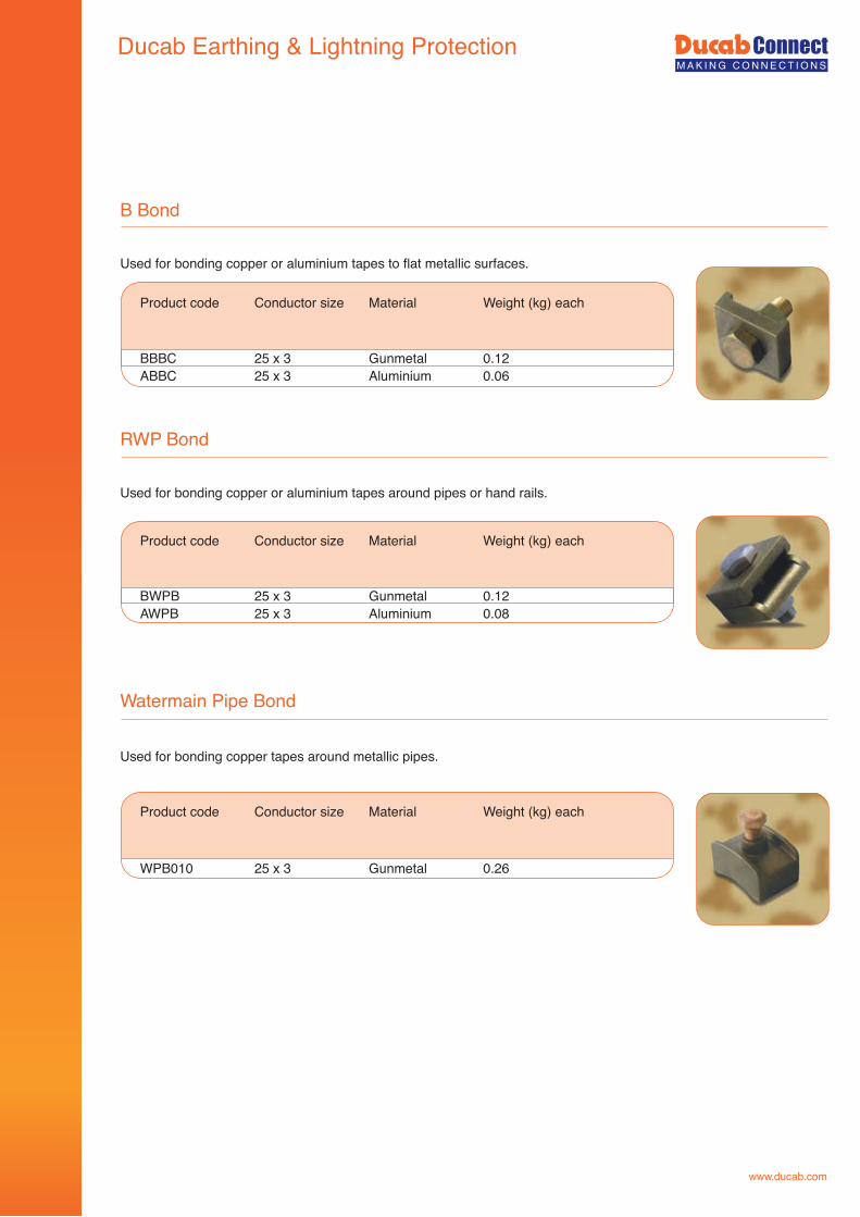
www.ducab.com
B Bond
Used for bonding copper or aluminium tapes to flat metallic surfaces.
RWP Bond
Watermain Pipe Bond
Used for bonding copper tapes around metallic pipes.
Product code Conductor size Material Weight (kg) each
WPB010 25 x 3 Gunmetal 0.26
BBBC 25 x 3 Gunmetal 0.12ABBC 25 x 3 Aluminium 0.06
Product code Conductor size Material Weight (kg) each
Used for bonding copper or aluminium tapes around pipes or hand rails.
Product code Conductor size Material Weight (kg) each
BWPB 25 x 3 Gunmetal 0.12AWPB 25 x 3 Aluminium 0.08
Ducab Earthing & Lightning Protection
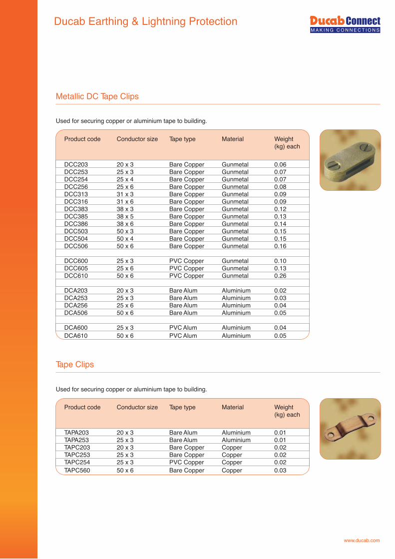
www.ducab.com
Metallic DC Tape Clips
Used for securing copper or aluminium tape to building.
Tape Clips
Used for securing copper or aluminium tape to building.
Product code Conductor size Tape type Material Weight (kg) each
TAPA203 20 x 3 Bare Alum Aluminium 0.01TAPA253 25 x 3 Bare Alum Aluminium 0.01TAPC203 20 x 3 Bare Copper Copper 0.02TAPC253 25 x 3 Bare Copper Copper 0.02TAPC254 25 x 3 PVC Copper Copper 0.02TAPC560 50 x 6 Bare Copper Copper 0.03
DCC203 20 x 3 Bare Copper Gunmetal 0.06DCC253 25 x 3 Bare Copper Gunmetal 0.07DCC254 25 x 4 Bare Copper Gunmetal 0.07DCC256 25 x 6 Bare Copper Gunmetal 0.08DCC313 31 x 3 Bare Copper Gunmetal 0.09DCC316 31 x 6 Bare Copper Gunmetal 0.09DCC383 38 x 3 Bare Copper Gunmetal 0.12DCC385 38 x 5 Bare Copper Gunmetal 0.13DCC386 38 x 6 Bare Copper Gunmetal 0.14DCC503 50 x 3 Bare Copper Gunmetal 0.15DCC504 50 x 4 Bare Copper Gunmetal 0.15DCC506 50 x 6 Bare Copper Gunmetal 0.16
DCC600 25 x 3 PVC Copper Gunmetal 0.10DCC605 25 x 6 PVC Copper Gunmetal 0.13DCC610 50 x 6 PVC Copper Gunmetal 0.26
DCA203 20 x 3 Bare Alum Aluminium 0.02DCA253 25 x 3 Bare Alum Aluminium 0.03DCA256 25 x 6 Bare Alum Aluminium 0.04DCA506 50 x 6 Bare Alum Aluminium 0.05
DCA600 25 x 3 PVC Alum Aluminium 0.04DCA610 50 x 6 PVC Alum Aluminium 0.05
Product code Conductor size Tape type Material Weight (kg) each
Ducab Earthing & Lightning Protection
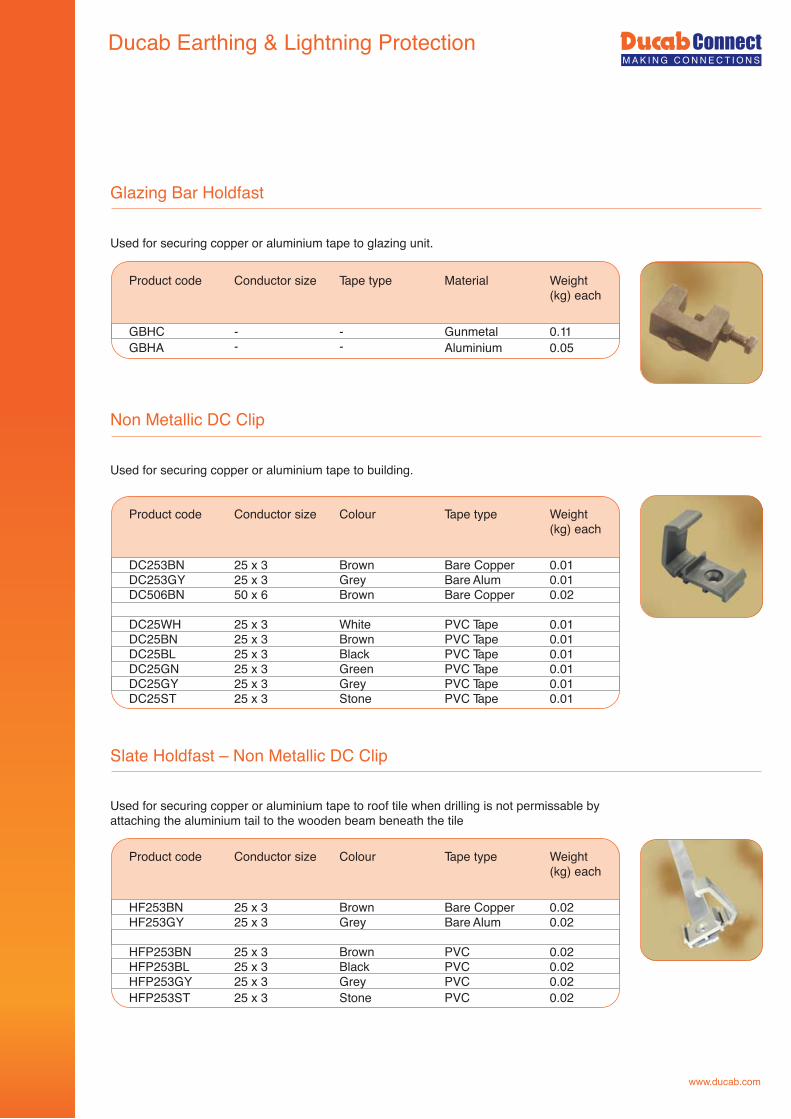
www.ducab.com
Glazing Bar Holdfast
Used for securing copper or aluminium tape to glazing unit.
Non Metallic DC Clip
Slate Holdfast – Non Metallic DC Clip
Used for securing copper or aluminium tape to roof tile when drilling is not permissable by attaching the aluminium tail to the wooden beam beneath the tile
Product code Conductor size Colour Tape type Weight (kg) each
HF253BN 25 x 3 Brown Bare Copper 0.02HF253GY 25 x 3 Grey Bare Alum 0.02
HFP253BN 25 x 3 Brown PVC 0.02HFP253BL 25 x 3 Black PVC 0.02HFP253GY 25 x 3 Grey PVC 0.02HFP253ST 25 x 3 Stone PVC 0.02
GBHC - - Gunmetal 0.11GBHA - - Aluminium 0.05
Product code Conductor size Tape type Material Weight (kg) each
Used for securing copper or aluminium tape to building.
Product code Conductor size Colour Tape type Weight (kg) each
DC253BN 25 x 3 Brown Bare Copper 0.01DC253GY 25 x 3 Grey Bare Alum 0.01DC506BN 50 x 6 Brown Bare Copper 0.02
DC25WH 25 x 3 White PVC Tape 0.01DC25BN 25 x 3 Brown PVC Tape 0.01DC25BL 25 x 3 Black PVC Tape 0.01DC25GN 25 x 3 Green PVC Tape 0.01DC25GY 25 x 3 Grey PVC Tape 0.01DC25ST 25 x 3 Stone PVC Tape 0.01
Ducab Earthing & Lightning Protection
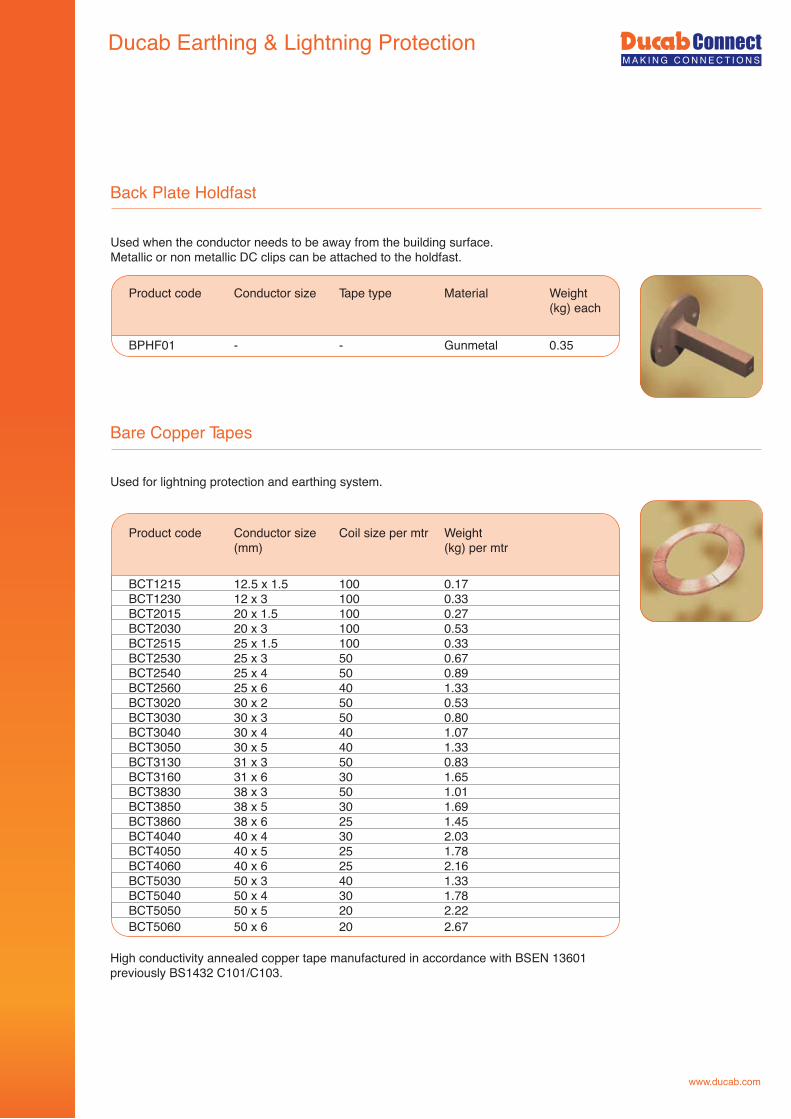
www.ducab.com
Bare Copper Tapes
Used for lightning protection and earthing system.
BCT1215 12.5 x 1.5 100 0.17BCT1230 12 x 3 100 0.33BCT2015 20 x 1.5 100 0.27BCT2030 20 x 3 100 0.53BCT2515 25 x 1.5 100 0.33BCT2530 25 x 3 50 0.67BCT2540 25 x 4 50 0.89BCT2560 25 x 6 40 1.33BCT3020 30 x 2 50 0.53BCT3030 30 x 3 50 0.80BCT3040 30 x 4 40 1.07BCT3050 30 x 5 40 1.33BCT3130 31 x 3 50 0.83BCT3160 31 x 6 30 1.65BCT3830 38 x 3 50 1.01BCT3850 38 x 5 30 1.69BCT3860 38 x 6 25 1.45BCT4040 40 x 4 30 2.03BCT4050 40 x 5 25 1.78BCT4060 40 x 6 25 2.16BCT5030 50 x 3 40 1.33BCT5040 50 x 4 30 1.78BCT5050 50 x 5 20 2.22BCT5060 50 x 6 20 2.67
Product code Conductor size Coil size per mtr Weight (mm) (kg) per mtr
Back Plate Holdfast
Used when the conductor needs to be away from the building surface.Metallic or non metallic DC clips can be attached to the holdfast.
Product code Conductor size Tape type Material Weight (kg) each
BPHF01 - - Gunmetal 0.35
High conductivity annealed copper tape manufactured in accordance with BSEN 13601 previously BS1432 C101/C103.
Ducab Earthing & Lightning Protection
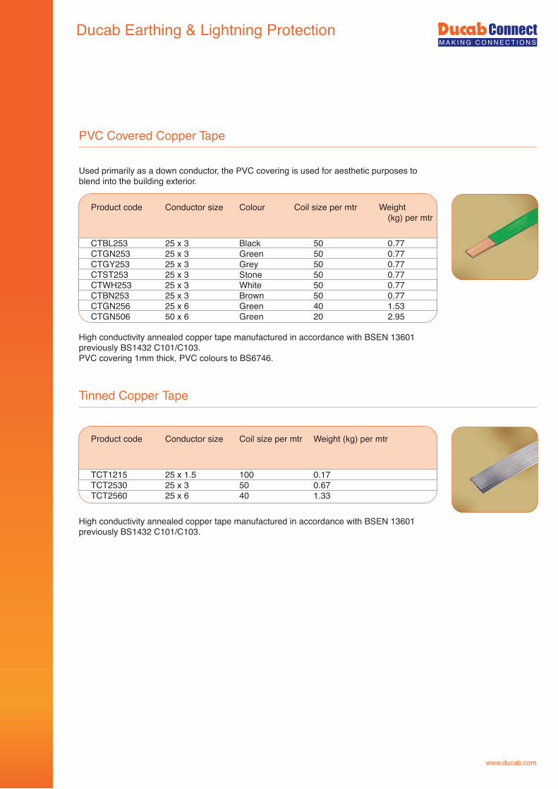
www.ducab.com
PVC Covered Copper Tape
Used primarily as a down conductor, the PVC covering is used for aesthetic purposes to blend into the building exterior.
Tinned Copper Tape
Product code Conductor size Coil size per mtr Weight (kg) per mtr
TCT1215 25 x 1.5 100 0.17TCT2530 25 x 3 50 0.67TCT2560 25 x 6 40 1.33
CTBL253 25 x 3 Black 50 0.77CTGN253 25 x 3 Green 50 0.77CTGY253 25 x 3 Grey 50 0.77CTST253 25 x 3 Stone 50 0.77CTWH253 25 x 3 White 50 0.77CTBN253 25 x 3 Brown 50 0.77CTGN256 25 x 6 Green 40 1.53CTGN506 50 x 6 Green 20 2.95
Product code Conductor size Colour Coil size per mtr Weight (kg) per mtr
High conductivity annealed copper tape manufactured in accordance with BSEN 13601 previously BS1432 C101/C103.PVC covering 1mm thick, PVC colours to BS6746.
High conductivity annealed copper tape manufactured in accordance with BSEN 13601 previously BS1432 C101/C103.
Ducab Earthing & Lightning Protection

www.ducab.com
Tinned PVC Covered Copper Tape
Used for lightning protection and earthing system.
TCT2530BL 25 x 3 Black 50 0.77TCT2530BR 25 x 3 Brown 50 0.77TCT2530GR 25 x 3 Green 50 0.77TCT2530GY 25 x 3 Grey 50 0.77TCT2530ST 25 x 3 Stone 50 0.77TCT2530WH 25 x 3 White 50 0.77
TCT2560BR 25 x 6 Brown 40 1.53TCT2560GR 25 x 6 Green 40 1.53TCT2560ST 25 x 6 Stone 40 1.53TCT2560WH 25 x 6 White 40 1.53
Product code Conductor size Colour Coil size per mtr Weight (kg) per mtr
High conductivity annealed copper tape manufactured in accordance with BSEN 13601 previously BS1432 C101/C103.PVC covering 1mm thick, PVC colours to BS6746.
Plain Copper Bar
HDB2503 25 x 3 - 4mtr 0.67HDB2506 25 x 6 - 4mtr 1.33HDB3806 38 x 6 - 4mtr 1.45HDB5006 50 x 6 - 4mtr 2.67HDB5010 50 x10 - 4mtr 4.45
Product code Conductor size Colour Random lengths Weight (kg) per mtr
Manufactured in accordance with BS2874 C101/C103.
Other sizes and lengths are available upon request.
Ducab Earthing & Lightning Protection
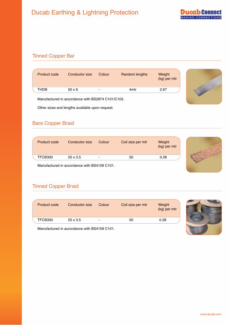
www.ducab.com
Tinned Copper Bar
Bare Copper Braid
Product code Conductor size Colour Coil size per mtr Weight (kg) per mtr
TFCB300 25 x 3.5 - 50 0.28
THDB 50 x 6 - 4mtr 2.67
Product code Conductor size Colour Random lengths Weight (kg) per mtr
Manufactured in accordance with BS2874 C101/C103.
Other sizes and lengths available upon request.
Manufactured in accordance with BS4109 C101.
Tinned Copper Braid
Product code Conductor size Colour Coil size per mtr Weight (kg) per mtr
TFCB350 25 x 3.5 - 50 0.28
Manufactured in accordance with BS4109 C101.
Ducab Earthing & Lightning Protection
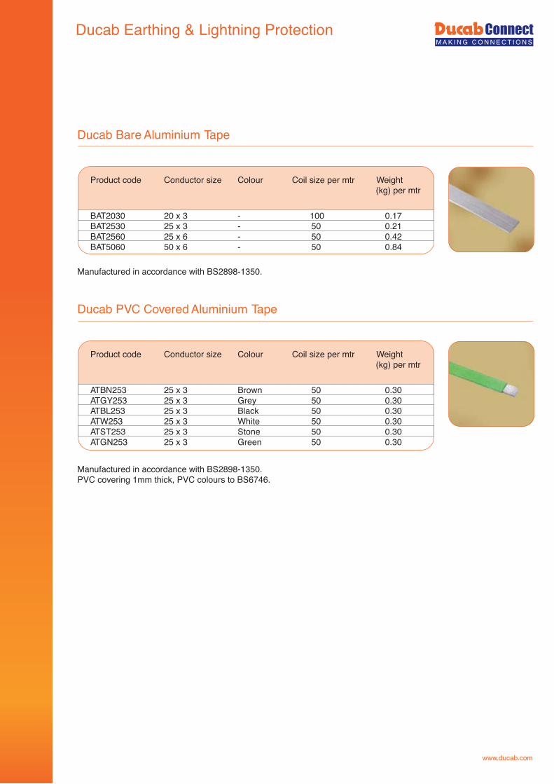
www.ducab.com
Ducab PVC Covered Aluminium Tape
ATBN253 25 x 3 Brown 50 0.30ATGY253 25 x 3 Grey 50 0.30ATBL253 25 x 3 Black 50 0.30ATW253 25 x 3 White 50 0.30 ATST253 25 x 3 Stone 50 0.30ATGN253 25 x 3 Green 50 0.30
Product code Conductor size Colour Coil size per mtr Weight (kg) per mtr
Manufactured in accordance with BS2898-1350. PVC covering 1mm thick, PVC colours to BS6746.
Ducab Bare Aluminium Tape
BAT2030 20 x 3 - 100 0.17BAT2530 25 x 3 - 50 0.21BAT2560 25 x 6 - 50 0.42BAT5060 50 x 6 - 50 0.84
Product code Conductor size Colour Coil size per mtr Weight (kg) per mtr
Manufactured in accordance with BS2898-1350.
Ducab Earthing & Lightning Protection
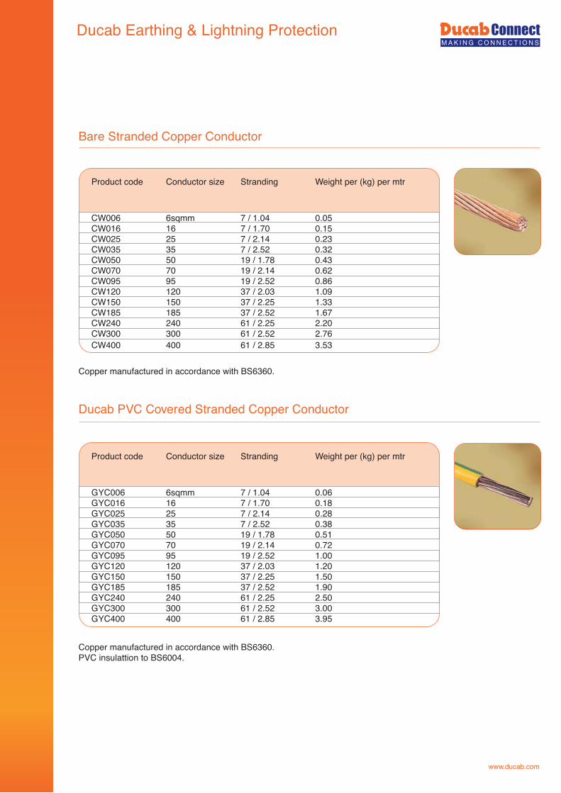
www.ducab.com
Bare Stranded Copper Conductor
Product code Conductor size Stranding Weight per (kg) per mtr
Copper manufactured in accordance with BS6360.
CW006 6sqmm 7 / 1.04 0.05CW016 16 7 / 1.70 0.15CW025 25 7 / 2.14 0.23CW035 35 7 / 2.52 0.32CW050 50 19 / 1.78 0.43CW070 70 19 / 2.14 0.62CW095 95 19 / 2.52 0.86CW120 120 37 / 2.03 1.09CW150 150 37 / 2.25 1.33CW185 185 37 / 2.52 1.67CW240 240 61 / 2.25 2.20CW300 300 61 / 2.52 2.76 CW400 400 61 / 2.85 3.53
Ducab PVC Covered Stranded Copper Conductor
Product code Conductor size Stranding Weight per (kg) per mtr
Copper manufactured in accordance with BS6360. PVC insulattion to BS6004.
GYC006 6sqmm 7 / 1.04 0.06GYC016 16 7 / 1.70 0.18GYC025 25 7 / 2.14 0.28GYC035 35 7 / 2.52 0.38GYC050 50 19 / 1.78 0.51GYC070 70 19 / 2.14 0.72GYC095 95 19 / 2.52 1.00GYC120 120 37 / 2.03 1.20GYC150 150 37 / 2.25 1.50GYC185 185 37 / 2.52 1.90GYC240 240 61 / 2.25 2.50GYC300 300 61 / 2.52 3.00 GYC400 400 61 / 2.85 3.95
Ducab Earthing & Lightning Protection
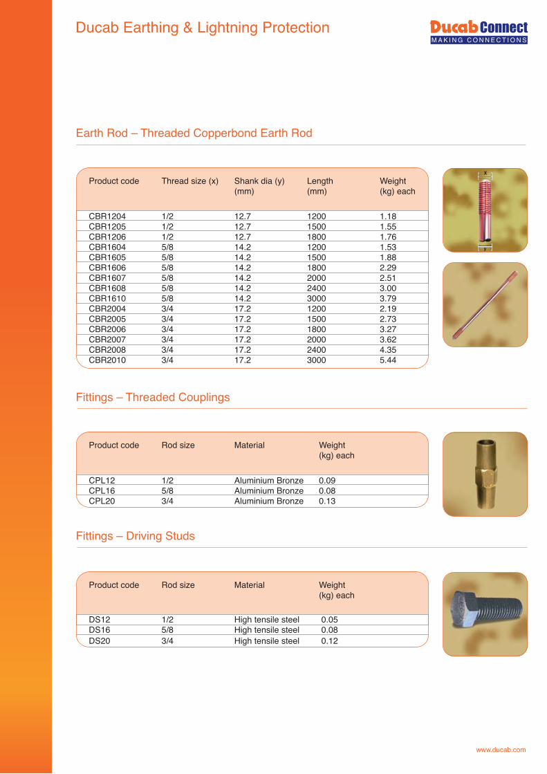
Ducab Earthing & Lightning Protection
www.ducab.com
Earth Rod – Threaded Copperbond Earth Rod
Product code Thread size (x) Shank dia (y) Length Weight (mm) (mm) (kg) each
CBR1204 1/2 12.7 1200 1.18CBR1205 1/2 12.7 1500 1.55CBR1206 1/2 12.7 1800 1.76CBR1604 5/8 14.2 1200 1.53CBR1605 5/8 14.2 1500 1.88CBR1606 5/8 14.2 1800 2.29CBR1607 5/8 14.2 2000 2.51CBR1608 5/8 14.2 2400 3.00CBR1610 5/8 14.2 3000 3.79CBR2004 3/4 17.2 1200 2.19CBR2005 3/4 17.2 1500 2.73CBR2006 3/4 17.2 1800 3.27CBR2007 3/4 17.2 2000 3.62CBR2008 3/4 17.2 2400 4.35CBR2010 3/4 17.2 3000 5.44
Fittings – Threaded Couplings
Product code Rod size Material Weight (kg) each
CPL12 1/2 Aluminium Bronze 0.09CPL16 5/8 Aluminium Bronze 0.08CPL20 3/4 Aluminium Bronze 0.13
Fittings – Driving Studs
Product code Rod size Material Weight (kg) each
DS12 1/2 High tensile steel 0.05DS16 5/8 High tensile steel 0.08DS20 3/4 High tensile steel 0.12
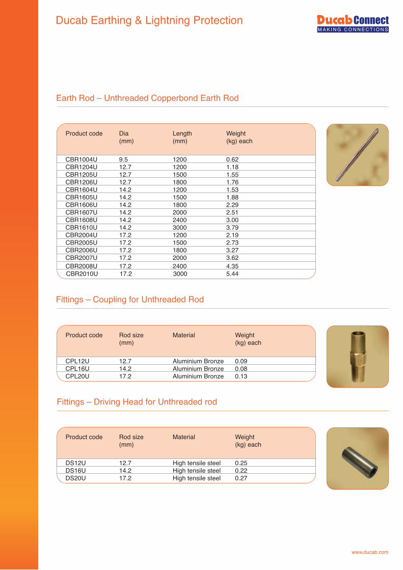
www.ducab.com
Earth Rod – Unthreaded Copperbond Earth Rod
Product code Dia Length Weight (mm) (mm) (kg) each
CBR1004U 9.5 1200 0.62CBR1204U 12.7 1200 1.18CBR1205U 12.7 1500 1.55CBR1206U 12.7 1800 1.76CBR1604U 14.2 1200 1.53CBR1605U 14.2 1500 1.88CBR1606U 14.2 1800 2.29CBR1607U 14.2 2000 2.51CBR1608U 14.2 2400 3.00CBR1610U 14.2 3000 3.79CBR2004U 17.2 1200 2.19CBR2005U 17.2 1500 2.73CBR2006U 17.2 1800 3.27CBR2007U 17.2 2000 3.62CBR2008U 17.2 2400 4.35CBR2010U 17.2 3000 5.44
Fittings – Coupling for Unthreaded Rod
Product code Rod size Material Weight (mm) (kg) each
CPL12U 12.7 Aluminium Bronze 0.09CPL16U 14.2 Aluminium Bronze 0.08CPL20U 17.2 Aluminium Bronze 0.13
Fittings – Driving Head for Unthreaded rod
Product code Rod size Material Weight (mm) (kg) each
DS12U 12.7 High tensile steel 0.25DS16U 14.2 High tensile steel 0.22DS20U 17.2 High tensile steel 0.27
Ducab Earthing & Lightning Protection
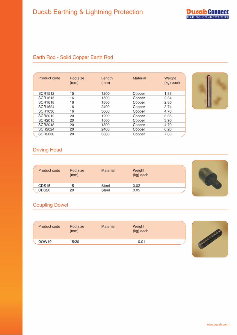
www.ducab.com
Earth Rod - Solid Copper Earth Rod
Product code Rod size Length Material Weight (mm) (mm) (kg) each
SCR1512 15 1200 Copper 1.88SCR1615 16 1500 Copper 2.34SCR1618 16 1800 Copper 2.80SCR1624 16 2400 Copper 3.74SCR1630 16 3000 Copper 4.70SCR2012
20
1200
Copper
3.35
SCR2015
20
1500
Copper
3.90SCR2018
20
1800
Copper
4.70
SCR2024
20
2400
Copper
6.20 SCR2030
20
3000
Copper
7.80
Driving Head
Product code Rod size Material Weight (mm) (kg) each
CDS15 15 Steel 0.02CDS20 20 Steel 0.05
Coupling Dowel
Product code Rod size Material Weight (mm) (kg) each
DOW10 15/20 0.01
Ducab Earthing & Lightning Protection
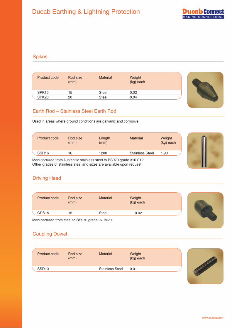
www.ducab.com
Spikes
Product code Rod size Material Weight (mm) (kg) each
SPK15 15 Steel 0.02SPK20 20 Steel 0.04
Earth Rod – Stainless Steel Earth Rod
Product code Rod size Length Material Weight (mm) (mm) (kg) each
SSR16 16 1200 Stainless Steel 1.90
Driving Head
Product code Rod size Material Weight (mm) (kg) each
CDS15 15 Steel 0.02
Coupling Dowel
Product code Rod size Material Weight (mm) (kg) each
SSD10 Stainless Steel 0.01
Used in areas where ground conditions are galvanic and corrosive.
Manufactured from Austenitic stainless steel to BS970 grade 316 S12.Other grades of stainless steel and sizes are available upon request.
Manufactured from steel to BS970 grade 070M20.
Ducab Earthing & Lightning Protection
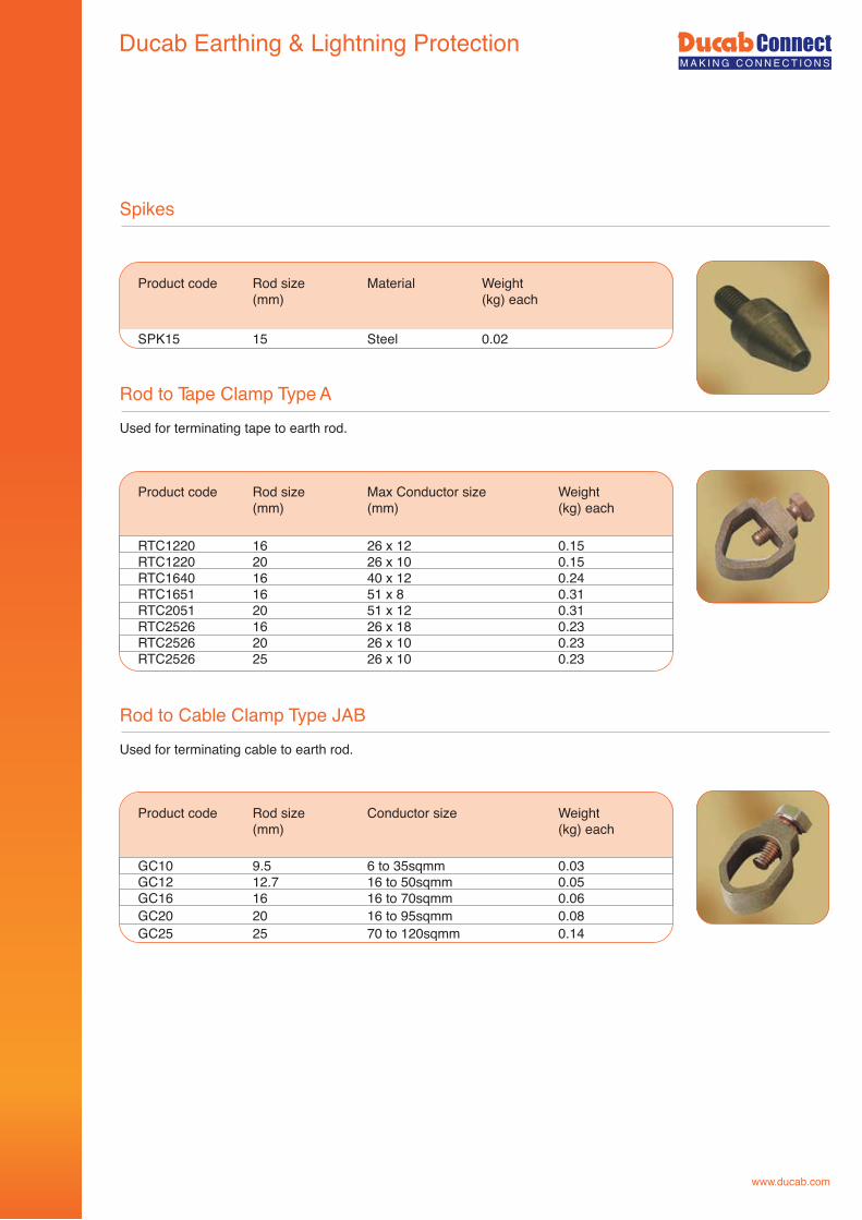
www.ducab.com
Spikes
Product code Rod size Material Weight (mm) (kg) each
SPK15 15 Steel 0.02
Rod to Tape Clamp Type A
Product code Rod size Max Conductor size Weight (mm) (mm) (kg) each
RTC1220 16 26 x 12 0.15 RTC1220 20 26 x 10 0.15RTC1640 16 40 x 12 0.24RTC1651 16 51 x 8 0.31RTC2051 20 51 x 12 0.31RTC2526 16 26 x 18 0.23RTC2526 20 26 x 10 0.23RTC2526 25 26 x 10 0.23
Used for terminating tape to earth rod.
Rod to Cable Clamp Type JAB
Product code Rod size Conductor size Weight (mm) (kg) each
GC10 9.5 6 to 35sqmm 0.03GC12 12.7 16 to 50sqmm 0.05GC16 16 16 to 70sqmm 0.06GC20 20 16 to 95sqmm 0.08GC25 25 70 to 120sqmm 0.14
Used for terminating cable to earth rod.
Ducab Earthing & Lightning Protection
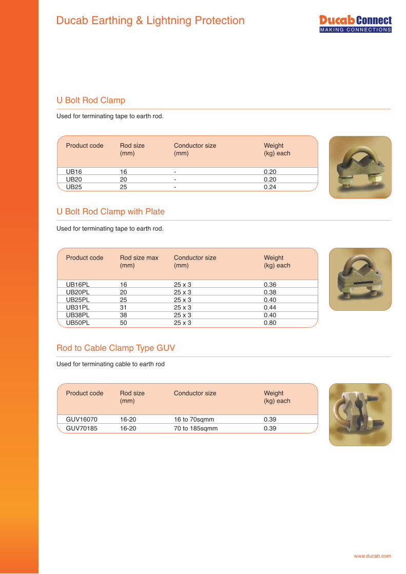
www.ducab.com
U Bolt Rod Clamp
Product code Rod size Conductor size Weight (mm) (mm) (kg) each
UB16 16 - 0.20UB20 20 - 0.20UB25 25 - 0.24
U Bolt Rod Clamp with Plate
Product code Rod size max Conductor size Weight (mm) (mm) (kg) each
UB16PL 16 25 x 3 0.36UB20PL 20 25 x 3 0.38UB25PL 25 25 x 3 0.40UB31PL 31 25 x 3 0.44UB38PL 38 25 x 3 0.40UB50PL 50 25 x 3 0.80
Rod to Cable Clamp Type GUV
Product code Rod size Conductor size Weight (mm) (kg) each
GUV16070 16-20 16 to 70sqmm 0.39GUV70185 16-20 70 to 185sqmm 0.39
Used for terminating tape to earth rod.
Used for terminating tape to earth rod.
Used for terminating cable to earth rod
Ducab Earthing & Lightning Protection
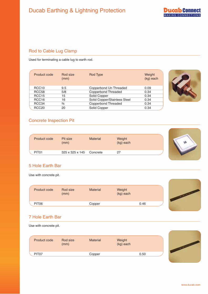
www.ducab.com
Rod to Cable Lug Clamp
Product code Rod size Rod Type Weight (mm) (kg) each
RCC10 9.5 Copperbond Un Threaded 0.09RCC58 5/8 Copperbond Threaded 0.34RCC15 15 Solid Copper 0.34RCC16 16 Solid Copper/Stainless Steel 0.34RCC34 ¾ Copperbond Threaded 0.34RCC20
20
Solid Copper
0.34
Concrete Inspection Pit
Product code Pit size Material Weight (mm) (kg) each
PIT01
325 x 325 x 145
Concrete
27
Used for terminating a cable lug to earth rod.
5 Hole Earth Bar
Product code Rod size Material Weight (mm) (kg) each
PIT06
Copper
0.46
Use with concrete pit.
7 Hole Earth Bar
Product code Rod size Material Weight (mm) (kg) each
PIT07
Copper
0.50
Use with concrete pit.
Ducab Earthing & Lightning Protection
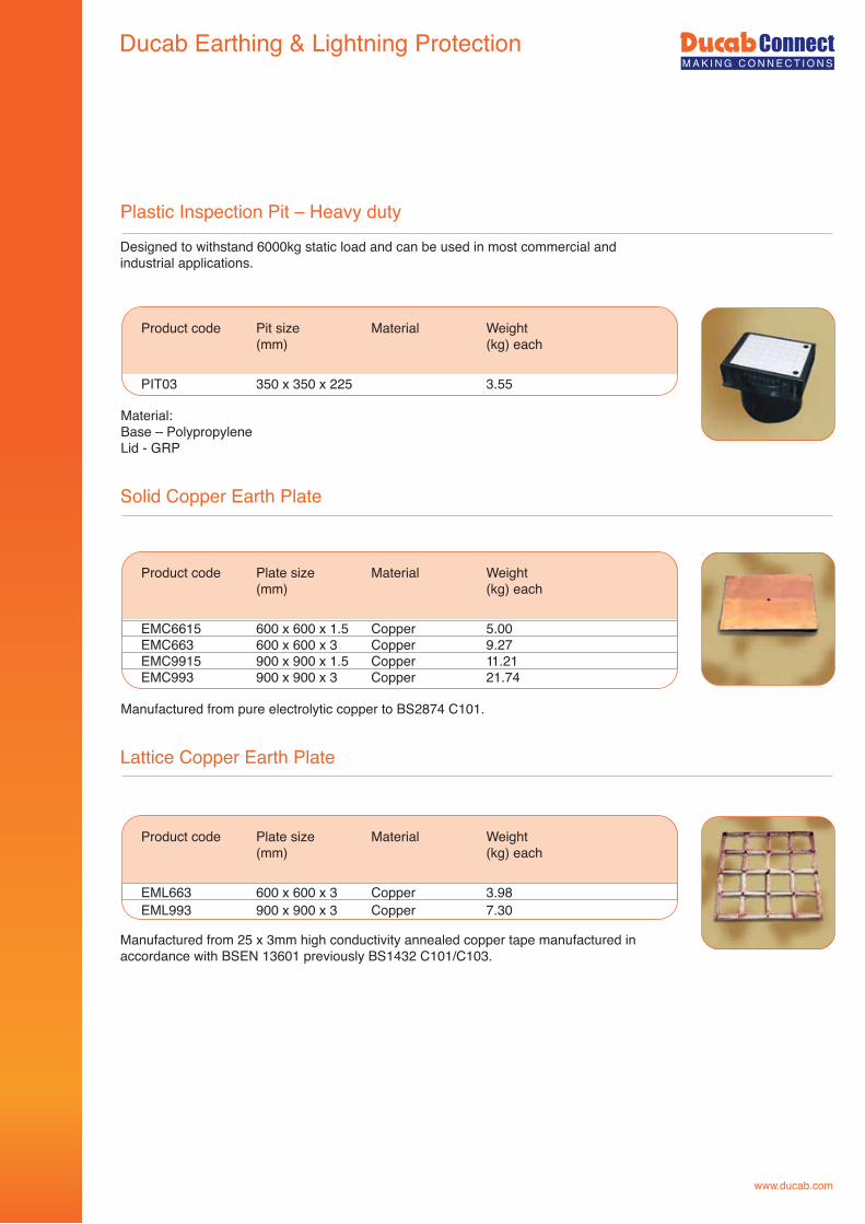
www.ducab.com
25
Plastic Inspection Pit – Heavy duty
Product code Pit size Material Weight (mm) (kg) each
PIT03 350 x 350 x 225 3.55
Solid Copper Earth Plate
Product code Plate size Material Weight (mm) (kg) each
EMC6615 600 x 600 x 1.5 Copper 5.00EMC663 600 x 600 x 3 Copper 9.27EMC9915 900 x 900 x 1.5 Copper 11.21EMC993
900 x 900 x 3
Copper
21.74
Lattice Copper Earth Plate
Product code Plate size Material Weight (mm) (kg) each
EML663 600 x 600 x 3 Copper 3.98EML993 900 x 900 x 3 Copper 7.30
Designed to withstand 6000kg static load and can be used in most commercial and industrial applications.
Material:Base – PolypropyleneLid - GRP
Manufactured from pure electrolytic copper to BS2874 C101.
Manufactured from 25 x 3mm high conductivity annealed copper tape manufactured in accordance with BSEN 13601 previously BS1432 C101/C103.
Ducab Earthing & Lightning Protection
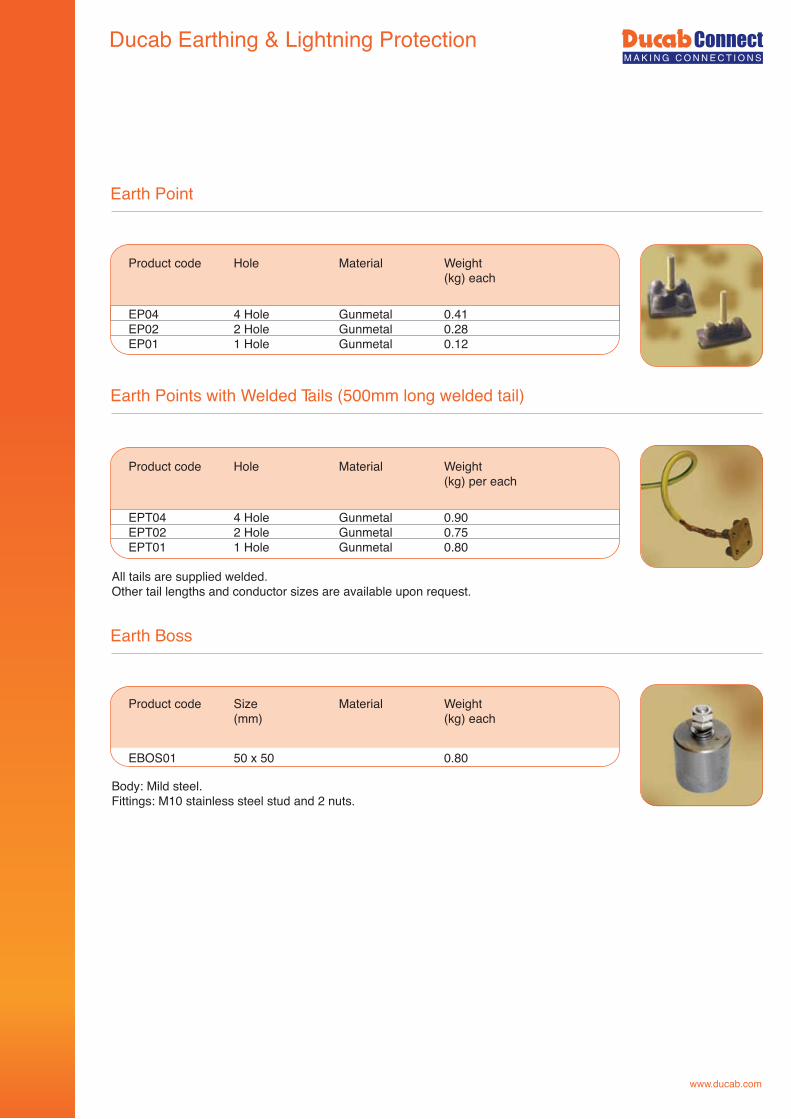
www.ducab.com
Earth Point
Product code Hole Material Weight (kg) each
EP04 4 Hole Gunmetal 0.41EP02 2 Hole Gunmetal 0.28EP01 1 Hole Gunmetal 0.12
Earth Points with Welded Tails (500mm long welded tail) (500mm lg welded tail)
Earth Boss
Product code Size Material Weight (mm) (kg) each
EBOS01
50 x 50
0.80
Body: Mild steel.Fittings: M10 stainless steel stud and 2 nuts.
All tails are supplied welded.Other tail lengths and conductor sizes are available upon request.
Product code Hole Material Weight (kg) per each
EPT04 4 Hole Gunmetal 0.90EPT02 2 Hole Gunmetal 0.75EPT01 1 Hole Gunmetal 0.80
Ducab Earthing & Lightning Protection
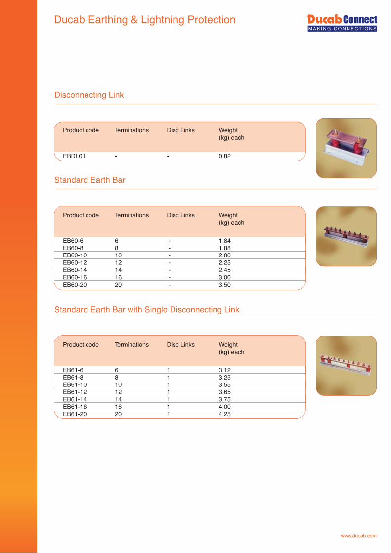
www.ducab.com
Standard Earth Bar with Single Disconnecting Link
Disconnecting Link
Product code Terminations Disc Links Weight (kg) each
EBDL01
-
-
0.82
Product code Terminations Disc Links Weight (kg) each
EB61-6 6 1 3.12 EB61-8 8 1 3.25 EB61-10 10 1 3.55 EB61-12 12 1 3.65 EB61-14 14 1 3.75 EB61-16 16 1 4.00 EB61-20 20 1 4.25
Standard Earth Bar
Product code Terminations Disc Links Weight (kg) each
EB60-6 6 - 1.84 EB60-8 8 - 1.88 EB60-10 10 - 2.00 EB60-12 12 - 2.25 EB60-14 14 - 2.45 EB60-16 16 - 3.00 EB60-20 20 - 3.50
Ducab Earthing & Lightning Protection
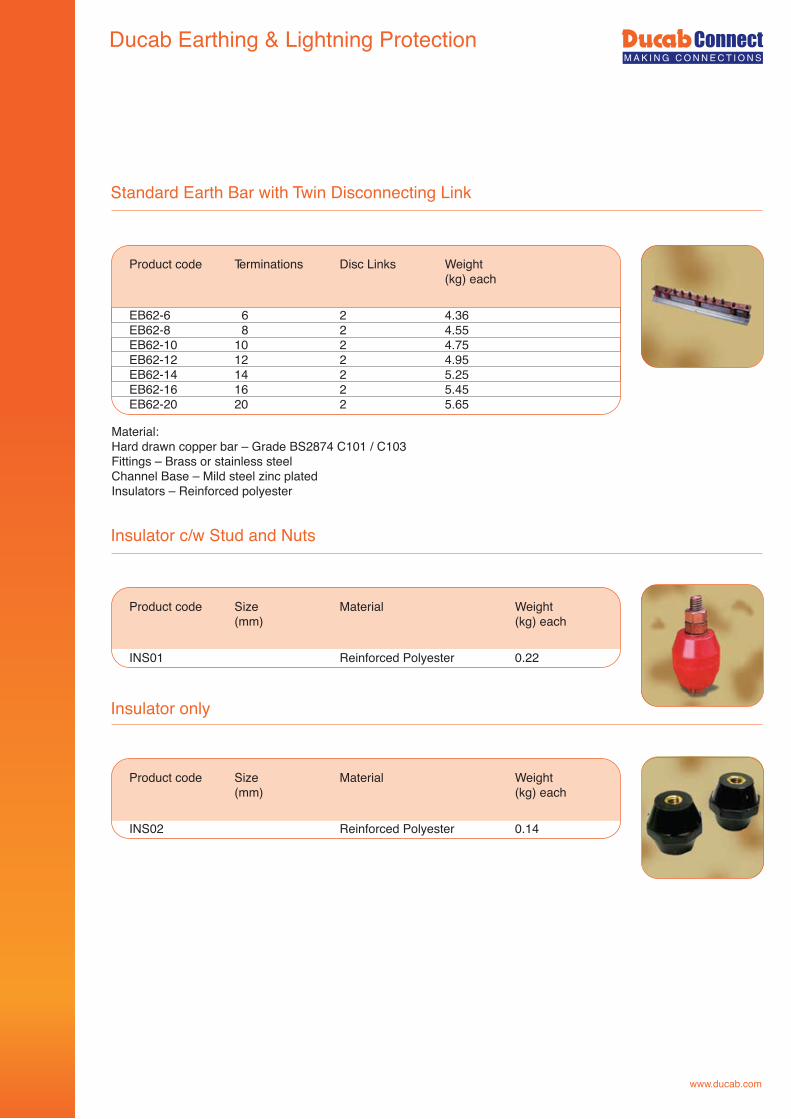
www.ducab.com
Insulator c/w Stud and Nuts
Product code Size Material Weight (mm) (kg) each
INS01 Reinforced Polyester 0.22
Standard Earth Bar with Twin Disconnecting Link
Product code Terminations Disc Links Weight (kg) each
EB62-6 6 2 4.36 EB62-8 8 2 4.55 EB62-10 10 2 4.75 EB62-12 12 2 4.95 EB62-14 14 2 5.25 EB62-16 16 2 5.45 EB62-20 20 2 5.65
Material:Hard drawn copper bar – Grade BS2874 C101 / C103Fittings – Brass or stainless steelChannel Base – Mild steel zinc platedInsulators – Reinforced polyester
Insulator only
Product code Size Material Weight (mm) (kg) each
INS02 Reinforced Polyester 0.14
Ducab Earthing & Lightning Protection
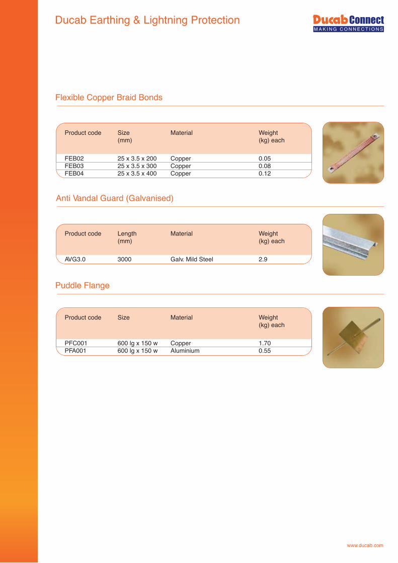
www.ducab.com
Flexible Copper Braid Bonds
Product code Size Material Weight (mm) (kg) each
FEB02 25 x 3.5 x 200 Copper 0.05FEB03 25 x 3.5 x 300 Copper 0.08FEB04 25 x 3.5 x 400 Copper 0.12
Anti Vandal Guard (Galvanised)
Product code Length Material Weight (mm) (kg) each
AVG3.0 3000 Galv. Mild Steel 2.9
Puddle Flange
Product code Size Material Weight (kg) each
PFC001 600 lg x 150 w Copper 1.70PFA001 600 lg x 150 w Aluminium 0.55
Ducab Earthing & Lightning Protection
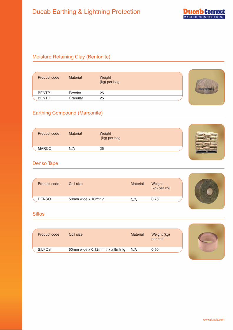
www.ducab.com
Moisture Retaining Clay (Bentonite)
Product code Material Weight (kg) per bag
BENTP Powder 25BENTG Granular 25
Earthing Compound (Marconite)
Denso Tape
Product code Coil size Material Weight (kg) per coil
DENSO 50mm wide x 10mtr lg N/A 0.76
Silfos
Product code Material
N/A
Weight (kg) per bag
MARCO 25
Product code Coil size Material Weight (kg) per coil
SILFOS 50mm wide x 0.12mm thk x 8mtr lg N/A 0.50
Ducab Earthing & Lightning Protection
Why use Ducab cable cleats for securing cables?Ducab cable cleats are designed to fix, retain and support cables. In addition, where short-circuit faults are anticipated, correct cleating will result in the containment of the cables during a fault and enable the circuit to be restored once the fault has been repaired.When adjacent cables carrying three phase current suffer a short circuit fault, the induced magnetic fields result in the cables experiencing significant opposing forces, a safe installation requires well designed and thoroughly tested cable cleats.
Short circuits and short circuit testingShort circuit current is given either as a “peak” or an “rms” value. The peak current is the maximum current experienced by any of the phases and it occurs once within the first few milliseconds of the start of the fault.The rms current is a calculated value for the initial cycles of the fault. The relationship between peak current and rms current varies from installation to installation.The forces experienced by a cleat during a short circuit are a function of short circuit current, cleat spacing and the distance between the cable centres (in the case of trefoil arrangements this is the cable diameter). When comparing short circuit test results for different products all three factors must be taken into consideration to compare the relative aggressiveness of the tests. The following formula taken from the draft Cenelec standard for cable cleats prEN 50368 calculates the force experienced by a cleat with cables arranged in trefoil formation:
This formula gives the static load instantaneously created by the short circuit, however the phase changes of the alternating current mean that the forces on the cable and their direction are changing continuously. No simple formula and no static test can assess the effect of these dynamic forces. The ultimate proof of any product to withstand a short-circuit is to undertake a short-circuit test.Short circuit tests are carried out on a regular basis at various testing stations including The British Short Circuit Testing Station, Hebburn (BSTS). This comprehensive testing program enables us to produce empirical results when developing new products as well as to ensure that our existing products meet the appropriate International Standards. Recent tests have been conducted in accordance with the requirements of the current draft European Standard.Ducab are happy to allow their cable cleats to be subjected to any comparative tests with competitors’ products.Copies of test reports and video footage of tests on CD Rom are available on request.
Where:Ft = maximum force on the cable conductor in trefoil formation for a three phase short-circuit (N/m)ip = the peak short-circuit current (kA)S = the cable diameter (m)
Ft = 0.17 x ip2
S
Ducab Cable Cleating Systems
www.ducab.com
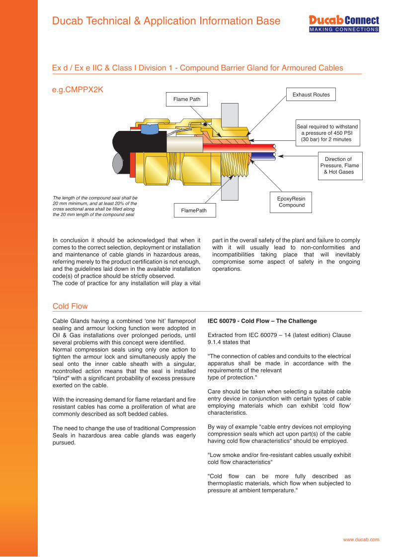
C CABLABLE ME MARKARKINGING & & IDEIDENTINTIFICFICATIATIONON EA EARTHRTHINGING & & LIGLIGHTIHTINGNG PROPROTECTECTIOTIONN CABCABLELE MANMANAGEAGEMENMENT PT PRODRODUCTUCTSS CABCABLELE ACCACCESSESSORIORIESES
www.ducab.com
Ducab - Head Office P.O. BOX 11529, Jebel AliDubai, United Arab EmiratesPh. +9714 8082 500Fax +9714 8082 599email [email protected]
Ducab Branch - OmanP.O. BOX 3542, 112 RuwiMuscat, Sultanate of OmanPh. +968 245 651 78Fax +968 245 643 02email [email protected]
BICC MET W.L.LP.O. BOX 11413, ManamaKingdom of BahrainPh. +973 177 497 61Fax +973 177 280 27email [email protected]
Ducab Qatar LLCP.O. BOX 23209, Street No.52Salwa Industrial Area, Doha State of Qatar Ph. +974 320 9077email [email protected]
Ducab – KSADammam, Plan 71, Al Fasel St.Farhan Al-Zuabi BuildingKingdom of Saudi ArabiaPh. +966 563 212 090
![KAIZEN CASE STUDIES COMPETITION [DUCAB Pvt. Ltd ... · 1 KAIZEN CASE STUDIES COMPETITION [DUCAB Pvt. Ltd.] [Manufacturing & Technical department] [Reduction in Changeover Time in](https://img.pdfslide.net/doc/110x75/5ecebbfa301270614365d71c/kaizen-case-studies-competition-ducab-pvt-ltd-1-kaizen-case-studies-competition.jpg)