Embed Size (px)
Citation preview

Duke T. PRESTON GILLESPIE, JR.Dk Vice PresidentrahEnergy® Oconee Nuclear Station
Duke EnergyONOl VP / 7800 Rochester Hwy.Seneca, SC 29672
864-873-447810 CFR 50.90 864-873-4208 fax
T. Gillespie@duke-energy. corn
July 20, 2012
Document Control DeskU.S. Nuclear Regulatory CommissionWashington, DC 20555-0001
Subject: Duke Energy Carolinas, LLCOconee Nuclear Station, Units 1, 2, and 3Docket Numbers 50-269, 50-270, and 50-287,Renewed Operating Licenses DPR-38, DPR-47, and DPR-55Licensing Basis for the Protected Service Water System - Responses toRequest for Additional Information - Supplement 1
References:
1. Letter from John Boska, Senior Project Manager, Division of OperatingReactor Licensing, Office of Nuclear Reactor Regulation, U.S. NuclearRegulatory Commission, to T. Preston Gillespie, Vice President, OconeeNuclear Station, Duke Energy Carolinas, LLC, "Request for AdditionalInformation (RAI) Regarding the License Amendment Requests (LARs) forthe Licensing Basis for the Protected Service Water System," June 11, 2012.
2. Letter from T. Preston Gillespie, Vice President, Oconee Nuclear Station,Duke Energy Carolinas, LLC, to the U.S. Nuclear Regulatory Commission,"Licensing Basis for the Protected Service Water System - Responses toRequest for Additional Information," dated July 11, 2012.
By letter dated June 11, 2012, Duke Energy Carolinas, LLC (Duke Energy) formallyreceived a Nuclear Regulatory Commission (NRC) Request for Additional Information(RAI) (Reference 1) associated with the design and licensing bases for the proposedProtected Service Water (PSW) system. Duke Energy responded to 41 of the 53 RAIitems by letter dated July 11, 2012 (Reference 2).
The Enclosure to this letter provides the responses to the remaining 12 RAI items (125,128, 139, 140, 141, 142, 144, 145, 147, 148, 160, and 162) from the June 11, 2012, NRCletter. The Attachment provides supplemental information for three (3) of the RAIresponses. In addition, the response to RAI item 141 is based on analysis that requiresvalidation. Upon completion of the validation, Duke Energy will provide a follow-upresponse on RAI item 141 by August 17, 2012.
If you have any questions in regard to this letter, please contact Stephen C. Newman,Regulatory Compliance Senior Engineer, Oconee Nuclear Station, at (864) 873-4388.
www. duke-energy corn

U. S. Nuclear Regulatory CommissionJuly 20, 2012Page 2
I declare under penalty of perjury that the foregoing is true and correct. Executed onJuly 20, 2012.
Sincerely,
T. Preston Gillespie, Jr.Vice PresidentOconee Nuclear Station
Enclosure - Responses to RAI ItemsAttachment - RAI Item Supplemental Information

U. S. Nuclear Regulatory CommissionJuly 20, 2012Page 3
cc: (w/enclosure/attachment)
Mr. John P. Boska, Project Manager(by electronic mail only)U. S. Nuclear Regulatory CommissionOffice of Nuclear Reactor Regulation11555 Rockville PikeRockville, MD 20852
Mr. Victor M. McCree, Administrator, Region IIU.S. Nuclear Regulatory CommissionMarquis One Tower245 Peachtree Center Ave., NE, Suite 1200Atlanta, GA 30303-1257
Mr. Andrew T. SabischNRC Senior Resident InspectorOconee Nuclear Station
Ms. Susan E. Jenkins, ManagerRadioactive & Infectious Waste ManagementSC Dept. of Health and Environmental Control2600 Bull St.Columbia, SC 29201

Enclosure
Duke Energy Responses to RAI Items

Enclosure - Response to RAI ItemsJuly 20, 2012 Page 1
RAI 125 [EEEB16]
In a letter dated December 16, 2011, enclosure 3, tab 2, in response to RAI 43, the licenseereferenced its submittal dated August 31, 2010, and a previous RAI 2-27. In its August letter, thelicensee stated that the loading on the PSW transformer, switchgears, and load centers will beanswered in a future RAI response submittal. However, the staff's review of the licensee'sresponses dated December 7, 2010, December 16, 2011, and January 20, 2012, did not findany discussion regarding equipment loading. Provide a table showing the PSW system worstcase electrical loadings at 13.9 kV, 4.16 kV, and 600 V buses, and all equipment, bus, andbreaker design ratings demonstrating that the worst-case loadings are within the design ratingof the associated equipment/bus/breaker.
Duke Energy Response:
A sketch and applicable tables listing electrical equipment loading versus equipment ratings forPSW 13.8 KV, 4.16 KV and 600 V buses is provided in the RAI #125 supplemental informationsection of the Attachment to this letter. The data in the tables is based on current PSW designinformation. While some of the values may change minimally with design completion, the DukeEnergy QA Program and associated design processes ensure that potential nonconformanceswith equipment design ratings will be resolved prior to placing the equipment in service.
RAI 128 [EEEB19]
In its letter dated December 16, 2011, in response to the staffs RAI 63, the licensee referencedcalculation OSC-9190, Revision 0, "PSW 125 V DC Power System Analysis." Provide asummary table showing all DC loads, required minimum voltage, maximum rated voltage, andthe calculated available voltages at the equipment terminal demonstrating that in all cases, thecalculated voltages are bounded by the minimum and maximum rated voltage.
Duke Energy Response:
The requested information is provided in the data table in the Attachment to this letter. The datacontained in the table demonstrates that the calculated voltages are bounded by the minimumand maximum rated voltages except as noted by note 6 of the table.
RAI 139 [EMCB4]
In addition to the seismic analysis discussion included in Section 9.7.1.2.5.2 of the March 16,2012 letter, for the proposed PSW system credited piping and pipe supports; HVAC systemcomponents and component supports, ducts and duct supports; which are important to safetyand/or need to be seismically qualified, please provide technical evaluation discussions whichaddress the structural analyses or evaluations performed and include, but not limited to, thefollowing.
a) Structural analysis methodology, validated assumptions and criteria.
b) Structural design inputs which as minimum include loads and load combinations utilizedin the structural analyses.
The response to RAI EMCB-4(b) should include guidance and criteria utilized such aswhether the design response spectra is developed in accordance with RG 1.6 and RG1.92 for combining modal responses; whether RG 1.61 is used for damping ratios; otherregulatory guidance, FSAR or SRP sections.
Enclosure - Response to RAI ItemsJuly 20, 2012 Page 2
In addition, please discuss guidance and criteria for monitoring of piping vibration levelsduring startup testing mentioned in UFSAR Section 9.7.1.2.5.3 of the March 16, 2012letter and whether it is in accordance with ASME OM-SG Part 3, UFSAR or otherapproved guidance. Also discuss monitoring of piping thermal motion to verify adequateclearance and restriction of movements.
c) Discussion of the results of the structural analyses and evaluations. Please includequantitative summaries of maximum stresses with a comparison to code of recordallowable stresses. Include only maximum stresses and data at critical locations (i.e.pipe anchors, equipment nozzles, penetrations, component connections, tie-ins toexisting piping, etc). For penetrations and equipment nozzles provide a summary ofloads compared to specific allowable values for the penetrations and nozzles.
d) Describe the method and criteria used for the interface between piping which is requiredto be seismically qualified and non-seismically qualified piping.
e) Describe how the interaction between seismic and non-seismic PSW SSCs (includingpiping) has been considered.
Duke Energy Response:
a) Structural Analysis consists of the following:
" Structural Design of new and/or existing pipe supports for the PSW project is inaccordance with American Institute of Steel Construction (AISC) Manual of SteelConstruction, 6th Edition per Oconee UFSAR Section 3.9.3.4.2, and Oconeespecifications OS-0027.00-00-0001 "Design Specification for Class A, B, C, D and FPipe Supports and Restraints," Revision 14, and OSS-0027.00-00-0002, "Procedures,Supplemental Requirements and Tolerances for Fabrication of Pipe Supports andRestraints," Revision 26, using hand calculations. Additionally, some analyses alsoutilize GTStrudl finite element modeling analysis for qualification of the members usingthe AISC Manual of Steel Construction 7 th Edition (Per RAI 137, the equations used fromthe 7th edition have been reconciled with the 6th edition). Attachment of new and/orexisting piping supports to existing structures is evaluated in accordance withspecification OSS-0027.00-00-0009, "Specification for the Evaluation ofSupport/Restraints and Equipment Structural Attachment Loads at Oconee NuclearStation (Including Keowee Hydro Station)," Revision 1.
* New and/or existing cable tray, and conduit supports affected by the PSW project areevaluated using linear elastic analysis in accordance with the Seismic QualificationUsers Group (SQUG) methodology as described in specification OSS-0254.00-00-4019 "Design Basis Specification for the Cable Tray Supports," Revision 5. Additionalguidance is given in EPRI 7151-D, "Cable Tray and Conduit System Seismic EvaluationGuidelines." In general, cable tray supports are evaluated for dead load, verticalcapacity, ductility, and lateral load as detailed in Generic Implementation Procedure(GIP) 3A Sections 8.3.1, 8.3.2, 8.3.3 and 8.3.4, respectively. Additionally, field runelectray/cable tray that is 6" by 6" or smaller, and 1/2" diameter through 4" field runconduits may be supported in accordance with specification OSS-0218.00-00-0025"Specification for the Installation of Field Run Cable Support Systems," Revision 12. Un-resolved seismic interaction concerns for cable tray, electray, and conduit is addressedas part of the final design process for the cable tray, electray, and conduit runs.Furthermore, attachment of new and/or existing cable tray supports to existing structuresis evaluated in accordance with specification OSS-0027.00-00-0009, "Specification for

Enclosure - Response to RAI ItemsJuly 20, 2012 Page 3
the Evaluation of Support/Restraints and Equipment Structural Attachment Loads atOconee Nuclear Station (Including Keowee Hydro Station)," Revision 1. ExistingOconee cable tray supports in the Auxiliary Building were reviewed and evaluated aspart of the resolution of Unrestricted Safety Issue (USI) A-46. Bounding cases ofraceway supports were evaluated in Oconee Calculation OSC-6734 "EQE InternationalA-46/IPEEE Seismic Evaluation: Analytical Review of Raceway Supports," Revision 0,using the SQUG GIP 3A criteria.
* New and/or existing Heating, Ventilation, and Air Conditioning (HVAC) supports affectedby the PSW project is evaluated in accordance with specification OSS-0235.00-00-0015,"Design Specification for HVAC Support and Restraint," Revision 4. Attachment of newand/or existing HVAC supports to existing structures is evaluated in accordance withspecification OSS-0027.00-00-0009, "Specification for the Evaluation ofSupport/Restraints and Equipment Structural Attachment Loads at Oconee NuclearStation (Including Keowee Hydro Station)," Revision 1. Refer to calculation OSC-10581,"Structural/Seismic Analysis on Fan Mounting for the Oconee PSW Building," RevisionD6, and OSC-10661, "Structural/Seismic Analysis of Ductwork, Hangers and Supports,"Revision 0, which provides a detail analysis of the HVAC system and components in thePSW Building and Auxiliary Building, respectively.
" The following supplements codes and standards cited for the structural attachment ofequipment within the PSW Building in proposed UFSAR section 9.7.1.2.5.2 of the March16, 2012 letter: The attachment of equipment housed within the PSW building isevaluated for worst-case resultant seismic loads by summing forces/moments producedby the vertical seismic acceleration and the controlling horizontal (east/west ornorth/south) seismic acceleration based on pertinent PSW Building developed in-structure response spectra presented in calculation OSC-9506, "Generation of SSE In-Structure Seismic Response Spectra for the PSW Building," Revision 0, accelerationmagnitude, and attachment geometry (see Section 3.7.2.5 of the Oconee UFSAR).Critical damping values are as specified in Section 3.7.1.3 of the Oconee UFSAR. Thedesign of concrete expansion anchors used to attach new and/or existing equipment arein accordance with specifications OSS-0020.00-00-0004, "Specification for the Design,Installation, and Inspection of Concrete Expansion Anchors," Revision 6 and OSS-0020.00-00-0006, "Specification for the Design, Installation, and Inspection of HiltiConcrete Anchors," Revision 5.
b) Structural Design Inputs
The Oconee Nuclear Station (ONS) is a two directional earthquake motion according to theUFSAR, Section 3.7.2.5. Therefore, the PSW structures, systems and components (SSCs)have been analyzed for maximum horizontal component (either X or Z) and the verticalcomponent (Y) for seismic loads applied simultaneously.
Loads
* Dead loads consist of the weight of the structure plus all equipment and materialspermanently fastened to, and supported by, the structure/component.
* Live loads are the loads produced by the use and occupancy of the building orstructure. They include the weight of all movable loads, including personnel, tools,miscellaneous equipment, movable partitions, cranes, hoists, parts of dismantledequipment, and stored material.

Enclosure - Response to RAI ItemsJuly 20, 2012 Page 4
* Seismic design response spectra as specified in Section 3.7.1.1 of the OconeeUFSAR. Critical damping values as specified in Section 3.7.1.3 of the OconeeUFSAR. Components of earthquake motion applied as specified in Section 3.7.2.5 ofthe Oconee UFSAR.
* Tornado loadings conform to Regulatory Guide 1.76, Revision 1
(Note: The PSW system is not credited for mitigation of station damage from turbinemissiles; therefore, turbine missiles are not considered in the design of PSW structures,systems, or components.)
Load Combinations
* Pipe Stress (Refer to specification OS-0027B.00-00-001, "Specification for Class A,B, C, D, E, F, G and H Piping Analysis for Code Compliance," Revision 10)
- Normal (Primary Stresses)
Pressure + DL
- Thermal Expansion (Secondary Stresses)
T + OBE anchor motion if not included in the upset combination.
- Upset
Larger of:
Pressure + DL + OBE (N-S + Vert.) + DYNS
Or
Pressure + DL + OBE (E-W + Vert.) + DYNSOr
Pressure + DL + DYNT
Faulted
Larger of:
Pressure + DL + SSE (N-S + Vert.) + DYNS
Or
Pressure + DL + SSE (E-W + Vert.) + DYNS
Or
Pressure + DL + DYNTWhere,
DL = Dead LoadT = Thermal ExpansionDYNS = Relief valve load steady state (as applicable)DYNT = Relief valve load transient (as applicable)OBE = Operational Basis EarthquakeSSE = Safe Shutdown EarthquakeDBE = Design Basis Earthquake (equals SSE)

Enclosure - Response to RAI ItemsJuly 20, 2012 Page 5
Pipe Supports (Refer to Specification OS-0027.00-00-001, "Design Specification forClass A, B, C, D and F Pipe Supports and Restraints," Revision 14.)
Normal
Hydro
Or
Thermal (use greater of hot or cold load)
+ Pressure (as applicable)+ Weight (Dead + Live Loads)+ Friction (as applicable - see Section 1-2.3)
UpsetThermal (use greater of hot or cold load)
+ OBE or Wind (as applicable)+ Pressure (as applicable)+ Weight (Dead + Live Loads)+ Steam/Water Hammer (as applicable)
Or
Thermal (use greater of hot or cold load)
+ OBE or Wind (as applicable)+ Pressure (as applicable)+ Weight (Dead + Live Loads)+ Relief Valve (Steady State)+ Steam/Water Hammer (as applicable)
Or
Thermal (use greater of hot or cold load)
+ Pressure (as applicable)+ Weight (Dead + Live Loads)+ Relief Valve (Transient)+ Wind (as applicable)+ Steam/Water Hammer (as applicable)
Faulted
Thermal (use greater of hot or cold load)
+ DBE (2 x OBE) or Tornado (as applicable)+ Pressure (as applicable)+ Weight (Dead + Live Loads)+ Steam/Water Hammer (as applicable)
Or
Thermal (use greater of hot or cold load)
+ DBE (2 x OBE) or Tornado (as applicable)+ Pressure (as applicable)+ Weight (Dead + Live Loads)+ Relief Valve (Steady State)+ Steam/Water Hammer (as applicable)

Enclosure - Response to RAI ItemsJuly 20, 2012 Page 6
Or
Thermal (use greater of hot or cold load)
+ Pressure (as applicable)+ Weight (Dead + Live Loads)+ Relief Valve (Transient)+ Tornado (as applicable)+ Steam/Water Hammer (as applicable)
HVAC Supports (Refer to Specification OSS-0235.00-00-0015, "Design Specificationfor HVAC Support and Restraint," Revision 4.)
- NormalDW
- UpsetDW ± OBE
- FaultedDW ± SSE
Where,
DW = Dead Weight of ductwork plus dead weight of the S/R.OBE = Operating Basis Earthquake loading determined by multiplying the
appropriate OBE acceleration by the participating mass.SSE = Safe Shutdown Earthquake loading determined by multiplying the
appropriate SSE acceleration by the participating mass.
For the Regulatory Guides and standards used to develop the PSW Building ResponseSpectra that was used to calculate PSW Building Pipe Stress, refer to RA1-141 Response.All other pipe stress analyses used existing design base spectra per specification OS-027B.00-00-0002, "Specification for the Seismic Displacements and Response Spectra forthe Turbine, Auxiliary, Reactor, and Standby Shutdown Facility Buildings," Revision 8.
The piping is analyzed for design temperature per applicable codes. The resultant thermalmovement is accounted for in pipe support design. This QA-1 piping is installed under theDuke Energy quality control program and QC completes inspection of the tolerances on allsupports once the system is water solid to verify design tolerances are met.
Duke Energy obtained baseline vibration data for the pump assemblies prior to delivery.The pumps will also be monitored during testing. The Oconee Piping Analysis EngineeringManual, Instruction #13 for Piping Vibration (PAEM-013) and the Duke EngineeringModification Process require vibration monitoring of systems in accordance with ASME OM-SG Part 3.
c) The PSW piping is designed in accordance with Oconee piping system Class F (OS-027B.00-00-0001, "Specification for Class A, B, C, D, E, F, G and H Piping Analysis forCode Compliance," Revision 10) and is qualified per Code U.S.A.S. B31.1.0 (1967). Thesafety related piping is analyzed using the SUPERPIPE piping analysis program to evaluatethe piping stresses and to develop support loads due to deadweight, thermal, andearthquake effects. Results provided by the model are compared to Code allowable valuesto determine acceptability and reported in Oconee stress calculations OSC-9206 "ProtectedService Water Main Header / CCW Min Flow, Prob. No: 4-PSW-01 ," Revision 3, OSC-9512,"Protected Service Water from PSW Pump Room to Units 1 & 2 Steam Generators, Problem
Enclosure - Response to RAI ItemsJuly 20, 2012 Page 7
No.: 4-PSW-02," Revision 0 and OSC-9241, "Protected Service Water HPI Pump MotorCooling Line, Problem No.: 4-14B-04," Revision 0.
* Maximum stress load capacity ratio (L/C) for U.S.A.S. B31.1.0 (1967) Codeequations range from 0.70 to 0.85 < 1.0 (i.e., adequate margins exist).
* Equipment nozzles LC range from 0.15 to 0.75 < 1.0, as judged against vendorallowables (i.e., adequate margins exist).
* Valve accelerations are less than values specified in Section 5.2 of OconeeSpecification OS-027B.00-00-0001 (2.5 g's OBE).
* Provisions for relative seismic anchor movements between structures are consideredat penetrations.
* Anchors of the modeled PSW piping systems are considered at equipment nozzlesand penetrations as applicable.
The PSW safety shower/eye-wash station located in the PSW Building is designed inaccordance with Oconee piping system Class D, QA Condition 4 (OS-027B.00-00-0001)and is qualified per Code U.S.A.S. B31.1.0 (1967). Results provided by the SUPERPIPEmodel are compared to Code allowable values to determine acceptability and reported inOconee stress calculations OSC-9906, "PSW Building Battery Room Shower Eye-WashStation Piping Analysis, Problem No.: 4-27-02," Revision 0. Applicable code provisions havebeen satisfied.
The PSW fire protection piping located in the PSW Building is designed in accordance withOconee piping system Class G & H, QA Condition 3 (OS-027B.00-00-0001) and is qualifiedper Code U.S.A.S. B31.1.0 (1967). Results provided by the SUPERPIPE model arecompared to Code allowable values to determine acceptability and reported in Oconeestress calculations OSC-9938, "Pipe Stress Calculation for PSW Building Fire Protection,Problem No.: 1-14A-14," Revision 0. Applicable code provisions have been satisfied.
SUPERPIPE is procured from Areva (Framatome-ANP) as QA-1, SDQA Category Bsoftware. The validation and verification of the software is by the vendor, Areva, under theirQA program. A copy of Areva's SUPERPIPE QA Manual may be found in Duke Energy's in-house verification document COM-0203.C6-17-0042. See SDQA-70024-COM for furtherinformation.
d) Refer to Oconee Specification OS-027B.00-00-0001, Section 4.3.4.6 for overlapped analysisbetween seismic and non-seismic piping. Overlapped piping is considered in Oconee stresscalculations OSC-9206 and OSC-9512 by selecting sufficient overlap regions based onpiping geometry and support configurations. As a minimum, the overlap region must includefive effective restraints in each of the orthogonal directions.
e) Pipe support loads generated by Oconee stress calculations OSC-9206, OSC-9512, andOSC-9241 are transmitted to the Mod/Support Design Group for further evaluation. Theinteraction between the piping systems and surrounding supporting structures are assessedin the applicable support calculations. Additionally, structures are classified and designedfor seismic events per specification OSS-0254.00-00-4010, "Design Basis Specification forthe Seismic Design," Revision 3, section 3.2.1. This classification provides protectionagainst unacceptable interactions in that the most critical structures, required to prevent theuncontrolled release of radioactivity, are classified as Class 1 and have the most extensiveseismic design. Less critical structures whose failure would not directly result in anuncontrolled release of radioactivity; but, which could adversely affect an orderly shutdown,maintenance of the reactor in a safe condition or power generation are classified as Class 2

Enclosure - Response to RAI ItemsJuly 20, 2012 Page 8
and also designed for seismic events. The remaining structures, which are not essential toorderly shutdown, maintenance of the reactor in a safe condition or power generation, areclassified as Class 3 and are not designed for seismic events. Therefore, Class 1 and 2interactions are considered seismic PSW SSCs and Class 3 is Non-seismic.(Note: Unless noted otherwise in the response to this RAI, all specifications referenced areexisting specifications that meet the current licensing basis of Oconee Nuclear Station).
RAI 140 [EMCB5]
Section 3.2.1.1.1 of the Oconee Nuclear Station (ONS) Updated Final Safety Analysis Report(UFSAR) describes Class 1 structures as those structures, systems and components (SSCs)which prevent uncontrolled release of radioactivity and are designed to withstand all loadingswithout loss of function. According to the ONS UFSAR mark-up included in the licensee's letterdated March 16, 2012, the protected service water (PSW) building has a seismic classificationof Category 1 and it is designated as a Class 1 structure.
a) Provide a detailed description of the design criteria and load combinations for structuraldesign and stability analysis of the PSW building and demonstrate compliance withSection 3.1.2 of the ONS UFSAR;
b) Provide a detailed description of the type of foundation(s) and supportingrock/soil/backfill strata, as applicable, used in the design of the PSW building;
c) Provide further information relative to the design features and mitigative measures thathave been incorporated in the design and construction of the PSW building to controlgroundwater infiltration;
d) Provide a detailed explanation of the load path from the PSW building superstructure tothe foundation elements and to the subgrade;
e) Provide the factor of safety against overturning, sliding and floatation and associatedacceptance criteria for all applicable design loading conditions; and
f) Provide the maximum soil bearing pressure and the associated allowable limits for allapplicable design loading conditions.
Duke Energy Response:
a. The PSW Building is designed for Natural Phenomena as specified in the UFSAR Section3.1.2. Load combinations and structural design criteria are given in specification OSS-0292.00-00-0001, Specification for Design and Implementation Support of the ProtectedService Water System, Revision 2. (Note: The PSW system is not credited for mitigation ofstation damage from turbine missiles; therefore, turbine missiles are not considered in thedesign of PSW structures, systems, or components.)
Load Combinations
Load Combinations which govern the design of the PSW Building are as specified inNUREG-0800, Standard Review Plan (SRP) 3.8.4 [DRAFT], Revision 2, AmericanConcrete Institute (ACI) 349-97 (as supplemented by Regulatory Guide 1.142), and

Enclosure - Response to RAI ItemsJuly 20, 2012 Page 9
American National Standards Institute (ANSI)/AISC N690-1984 as supplemented byAppendix F of SRP Section 3.8.4.
(Note: Governing load combinations are the same as those presented in ACI 349-97 assupplemented by RG 1.142 as they are in SRP 3.8.4. The load factors presented in SRP3.8.4 in some instances exceed those within ACI 349-97/RG 1.142 for load cases whichdo not govern the design of the PSW Building. In either case the enveloping loadcombination is used. (The same applies for ANSI/AISC N690-1984 vs. SRP 3.8.4) TheStrength Design Method was used for concrete and Allowable Stress Design was usedfor steel. Separate load combinations were used for the analysis of steel and concrete.)
Structural Desi-qn Criteria
Loads
- Dead loads consist of the weight of the structure plus all equipment and materialspermanently fastened to, and supported by, the structure/component.
- Live loads are the loads produced by the use and occupancy of the PSW Building.They include the weight of all movable loads, including personnel, tools,miscellaneous equipment and stored material. (Note: Pipe loads within the PSWBuilding are incorporated within the live loads, which were included in the analysisand design of the PSW Building. This is consistent with the load combinations usedin SRP 3.8.4 as pipe loads have the same load factors as live loads.)
- The design wind velocity is 95 mph. The applied wind pressures are computed bythe means outlined in American Society of Civil Engineers (ASCE) Paper No. 3269which states that the equivalent static force on the building is equal to the dynamicpressure (q) times the drag coefficient (Cd) multiplied by the elevation area (ONSUFSAR Section 3.3.1).
- Seismic design response spectra are as specified in Section 3.7.1.1 of the OconeeUFSAR. Critical damping values are as specified in Section 3.7.1.3 of the OconeeUFSAR. Components of earthquake motion applied as specified in Section 3.7.2.5 ofthe Oconee UFSAR. See response to RAI 141 for specific information ondevelopment of seismic response spectra for PSW Building.
- Tornado loadings conform to Regulatory Guide 1.76, Revision 1.
Codes and Standards
- Concrete: Subsection C of Regulatory Guide 1.142, Revision 2 (i.e., ACI 349-97(except for Appendix B) as supplemented by Regulatory Guide 1.142 andsupplemented by Regulatory Guide 1.199, November 2003).
- Structural steel and plates: Subsection 11.2 of Standard Review Plan (SRP) Section3.8.4 [DRAFT] Revision 2 (i.e., ANSI/AISC N690-1984 as supplemented byAppendix F of SRP Section 3.8.4).
- Anchoring components and structural supports in concrete: Subsection C ofRegulatory Guide 1.199 (i.e., Appendix B (February 2001) to ACI 349-01 assupplemented by Regulatory Guide 1.199).
- Foundations: Subsection 11.3 of SRP Section 3.8.5, Subsection 11.4.a of SRP Section3.8.5, DRAFT Revision 2 (including SRP Section 3.7.2, DRAFT Revision 3 methodsfor combining three components of earthquake to compute overturning moment),Subsection 11.5 of SRP Section 3.8.5, and NUREG/CR-6896, February 2006.

Enclosure - Response to RAI ItemsJuly 20, 2012 Page 10
- Structural acceptance criteria: Subsection 11.5 of SRP Section 3.8.4, DRAFT
Revision 2
Flood Design
The PSW Building is not designed for an external flood event associated with the postulatedfailure of upstream dams.
The PSW system is credited for the mitigation of high energy line break(s) in the TurbineBuilding that may result in internal flooding of the Turbine Building caused by a resultingfailure of the Condenser Circulating Water (CCW) piping or expansion joint. The maximumwater level resulting from the bounding CCW expansion joint failure is 795.0 ft., which wouldbe contained within the Turbine Building. The grade level entrance of the PSW Building is797.0 ft. Since the maximum internal flood level is below the grade level entrance to thePSW Building, the structure will remain unaffected by internal flooding in the TurbineBuilding.
b. The PSW Building foundation is supported by a continuous exterior spread footer withinternal walls on spread footers and the battery room supported on a structural slab ongrade, refer to drawing O-398-A2-1 01, PSW Building Foundation Plan Sections & Details.All footers (for internal and external walls) were cast monolithically or with intentionallyroughened surfaces to ensure aggregate interlock within the concrete, and reinforcement iscontinuous throughout the footers, therefore all footers are interconnected. The east exteriorwall footer is supported on concrete fill that extends below the adjacent CCW pipes. Thenorth, south and west exterior walls, interior walls and battery room slab on grade are allfounded on compacted structural fill, procured and placed in accordance with ONSspecifications and design documents; refer to drawing O-398-A2-1 00, PSW BuildingGeneral Notes & Reference Drawings.
c. The PSW Building is water resistant up to Elevation 797'-0" the equipment operatingelevation. Waterstops are installed at slab to wall construction joints with the foundationwalls being a continuous placement. Refer to drawings O-398-A2-101, PSW BuildingFoundation Plan Sections & Details, and O-398-A3-401, PSW Building Foundation Sections& Details, Sheet 1, for details and locations.
Where High Pressure Service Water (HPSW) and Plant Drinking Water (PDW) pipingpenetrates the foundation walls link seals are provided, as shown on drawing O-398-A2-401, PSW Building Elevation Sections & Details. There are two floor drains in the PSWBuilding, one common for the two battery rooms and one in the cable spreading area belowthe equipment operating elevation. The battery room drain is within a trench, the top ofwhich is Elevation 797'-0", so that any water backing up through the stormwater system iscontained within the trench, while the cable spreading area floor drain has a backflowpreventor to isolate it from the outside stormwater system. Along the north end of the westexterior foundation wall, core bores were made after the foundation was constructed, forplacement of electrical conduits. These penetrations and conduits are sealed in accordancewith Duke Energy procedures using an RTV foam sealant. Along the north foundation wall, aportion of the existing wall concrete was hydrolazed to allow the placement of PSWDuctbank segment 9. This segment was provided after the PSW Building foundation hadbeen constructed to provide spare electrical conduit raceway capacity for future engineeringchanges. The area hydrolazed had a new waterstop placed along the bottom with non-shrink grout placed around the perimeter of the removed concrete area. Finally, the outsidesurface of the foundation wall and the perimeter of ductbank segment 9 intersecting the wallwere coated with a bitumastic sealant. Details of this are shown on drawing O-398-A3-404A,

Enclosure - Response to RAI ItemsJuly 20, 2012 Page 11
PSW Building North Foundation Wall Segment 9 Ductbank Intersection Sections and
Details.
The HPSW and PDW pipes are non-seismically designed outside of the PSW Buildings. Asstated in the RAI 139 response the HPSW pipe and supports are QA-3/QA-4 (FireProtection/Seismic Category II) and the PDW pipe and supports are QA-4 (SeismicCategory II), therefore they are both seismically designed inside the PSW Building. Pipingpenetrations into the PSW Building are designed for differential movement by providing apipe sleeve with a flexible linkseal as a water barrier. This design ensures adequateflexibility exists to accommodate any differential movement between the piping and the PSWBuilding concrete structure during a seismic event. Additional information on the details ofthese penetrations is provided in RAI 146.
d. The PSW Building is a reinforced concrete structure with a combination reinforced concreteand steel grating operating floor. The roof is supported on 4 sides by the exterior reinforcedconcrete walls. The concrete slabs are supported by a series of walls and beams aroundtheir perimeters at regular intervals. The steel grating is supported on steel floor framingmembers which span between exterior reinforced concrete walls and interior walls, all whichare supported by reinforced concrete strip footings. The main steel girders are supported attheir midspans by steel columns. All interior and exterior reinforced concrete walls and steelcolumns are supported directly on reinforced concrete strip footings which are in contactwith the soil foundation. The bottoms of the footings are at 7.75' below grade.
The battery room on the South end of the building is a slab on grade. The center wall issupported directly on a strip footing approximately 2 feet below grade and the perimeterexterior walls rest on a foundation 7.75' below grade.
The PSW Building was not designed using a simplified analysis for concrete design(one/two way slab). Internal forces and moments in the roof were determined by a 3D FiniteElement Analysis (FEA) utilizing STAAD-PRO. These internal forces and moments wereused to select reinforcement based on the criteria of ACl 349-97. At the center of the roofthe slab will behave as a one way slab, and at the North and South ends the roof willbehave as a two way slab. The enveloping moments from each span (North-South andEast-West) were used to conservatively determine appropriate reinforcement throughout theentire roof.
The FEA model included large openings in walls and slabs, and modeled all concrete andsteel structural members within the PSW Building. Lateral forces will be resisted by exteriorand interior concrete walls and slabs as well as the main floor girders which span East toWest in the PSW Building. Larger wall spans are designed with adequate reinforcement toresist lateral forces without additional support from other structural members.
(Note: fc' = 5,000 psi and fy = 60,000 psi for reinforced concrete design)
e. The required overturning Factor of Safety is 1.5 for OBE and Wind, 1.1 for SSE andTornado per SRP 3.8.5, Section 11.5. The factor of safety against overturning for the PSWBuilding exceeds this criteria.
The required sliding Factor of Safety is 1.5 for the Operational Basis Earthquake (OBE) andWind, 1.1 for SSE and Tornado per SRP 3.8.5 Section 11.5. The factor of safety againstsliding for the PSW Building exceeds this criteria.
The water table in the area of the PSW Building is located at Elev. 752'-0" per OSC-9227,Report of Geotechnical Exploration for Protected Service Water System and NaturalPhenomenon Barrier System Projects. The groundwater elevations are based upon

Enclosure - Response to RAI ItemsJuly 20, 2012 Page 12
observational wells from June 2007 and historical data collected for the construction of theRadwaste Building in May 1980. The PSW Building foundation is located at Elev. 788'-3."The base of the foundation is 36'-3" above the water table in this area, therefore flotation isnot considered (Reference drawings O-398-A2-100A, PSW Building Reference Specs,Schedules & Details, and O-398-A2-101, PSW Building Foundation Plan Sections & Details,for foundation elevations).
(Note: Information contained in Figure 2-41 of the Oconee UFSAR represents groundwaterat elevation 792'-0." Numerous groundwater wells have been installed since 1966 andobservations over the years support the data presented in OSC-9227. The information fromFigure 2-41 also represents groundwater before construction of Oconee Nuclear Station.)
f. The allowable soil pressure is calculated in OSC-9227, Report of Geotechnical Explorationfor Protected Service Water System and Natural Phenomenon Barrier System Projects. Thevalues presented for the PSW Building range from 5.85 ksf (Normal loads) to 10.69 ksf(Faulted Loads - SSE). Analysis of PSW Building foundation loads for all load cases arecalculated in OSC-9230, PSW Building Structural Analysis, and the design passes withadequate design margin.
RAI 141 [EMCB6]
According to the licensee's letter dated March 16, 2012, the ONS UFSAR mark-up includedSection 9.7.1.2.5.1 which states the following:
"The design response spectra for the new structures correspond to the expected maximumbedrock acceleration of 0.1g (MHE). The design response spectra were developed inaccordance with Regulatory Guide 1.122 (Reference 15). The dynamic analysis is made usingthe STAAD-PRO computer program. The structure is built on structural fill. A ground motiontime history was developed based on the soil properties and amplified response spectragenerated at elevations of significant nodal mass."
Provide the following:
a) Considering that the PSW building is described as founded on the structural fill, providea detailed description of rock motion, anchoring point for the input motion, and materialproperties of soil profile(s) overlaying bedrock (thickness, shear wave velocity, and otherrelevant material properties.) Also, discuss the response amplification calculationprocess that was used to determine the free-field horizontal and vertical ground motionat the PSW building.
b) Provide a detailed description of the procedures used for the seismic analysis of thePSW building and to develop the in-structure response spectra (floor design responsespectra). If different from the methods and acceptance criteria outlined in the NRCstandard review plan (SRP) 3.7.1 and 3.7.2, identify those differences and providejustification that the PSW building is adequately designed, using these alternativemethods, to withstand the effects of earthquake loads.
c) Confirm and provide further information that STAAD-PRO and all features of thissoftware related to the dynamic response analysis and static analysis have been verifiedand validated by its provider in compliance with 10 CFR Part 50, Appendix 8 and 10CFR Part 21. Also, provide documentation which demonstrates that the softwareprovider has been audited and approved as an Appendix 8 supplier.
d) Describe the method of combination of modal responses and spatial components usedin the PSW building seismic response analysis. If different from the methods outlined in

Enclosure - Response to RAI ItemsJuly 20, 2012 Page 13
the NRC Regulatory Guide (RG) 1.92, identify those differences and discuss how thesealternative methods provide assurance that the PSW building is adequately designed towithstand the effects of earthquake loads.
Duke Energy Response:
a) Detailed Description of Rock Motion
The acceleration time history used to analyze the seismic response of the soil profilebeneath the PSW Building is the El Centro N/S time history scaled to a peakacceleration of 0.10g; refer to OSC-7944 (MACTEC Calculation No. OCO-36), "ShakeAnalyses for Response Spectra for the PSW Building." The instrument that recordedthis particular accelerogram was attached to the El Centro Terminal SubstationBuilding's concrete floor, and is generally considered as representative of rock outcropmotion.
Anchoring Point of the Input Motion
The horizontal and vertical spectral acceleration curves were anchored at a spectralacceleration value of 0.272g at the period of 0.01 second for both 2-percent and 5-percent damping considered in the SHAKE 91 analyses. The value of 0.272grepresents the maximum seismic acceleration to be experienced by an infinitely rigidstructure with infinitely high natural frequency located at the ground surface, refer toOSC-7944.
Material Properties of Soils
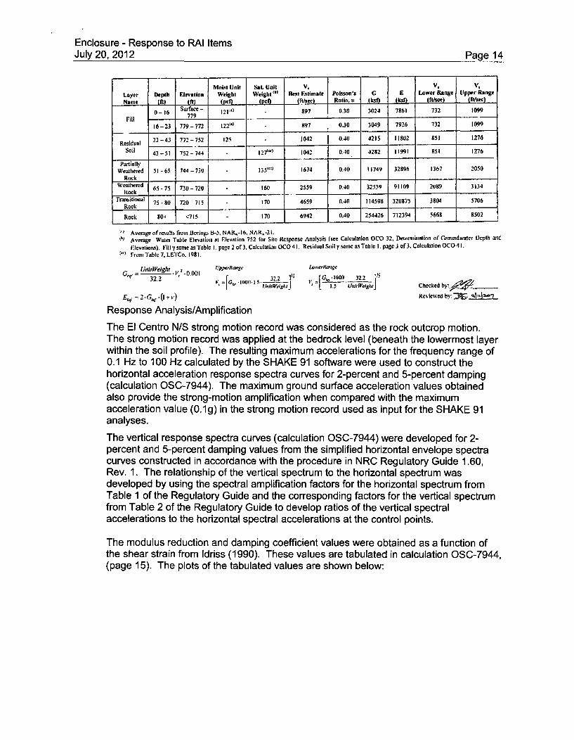
The soil/rock profile and the associated parameters used in the site response analysesof the PSW Building are shown below (refer to OSC-7941 (MACTEC Calculation No.OCO-31), "Shear Wave Velocities and Moduli for the PSW Building." Structural fillconstitutes the upper 23 feet of the soil profile. Beneath the fill, the soil profile graduallytransitions into rock. Bedrock was estimated to be at a depth that exceeds 80 feetbeneath the existing ground surface.
Enclosure - Response to RAI ItemsJuly 20, 2012 Page 14
Moiist Unit Sal. Unit V, V. V.
Layer Depth Elevation Weight Weight B Rest Fqtimale Poisson's G E Lower Range Upper Range
Name (Mt) ML , ( Je (Pe (fltic) Ratio, u ksn (.ksf) [ fl/see) (fl/sec)
0-16 Surface - 12,) 897 0.30 3024 7861 732 1099Fill 779
16-23 779-772 122"') 897 1 0.30 3049 7926 732 1099
Residual 23-43 772-752 125 1042 0.40 4215 11802 851 1276
soil 43-51 752-744 - l27i*'l 1042 0.40 4282 11991 £51 1276
PartiallyWeathered 51 -65 744 -730 1- 35t') 1674 0.40 11749 32896 1367 2050
RockWeathered 65-75 730-720 160 2559 0.40 32539 91109 2089 3134
IRock
Tranbilioual 75-80 720 715 170 4659 0.40 114598 320875 3804 5706Rock
Rock 90' <715 170 6942 0.40 254426 712394 5668 8502
" Average of results from Borings B-5, NAR,-16. NAR.-21.• Average Wate Table Elevalion at Elevation 752 tor Site Response Analysis (see Calculation OCO 32, Determialioa nfiGroumdwater Depth one
'lcvations). Filly same asTable I. page 2 of3. Calculation OCO4I. Residual Soil ,•sme w Table I. page 3 of3. Calculation OCO41.Frotm Table 7. LEICo, 198 1.
tJ,1i1Weigh: I/,2 "0.001 r./perR, ,,' Lor,',ge
32.2 100 32.232.2 *~o~~ I'Aft~egl, j - . UuI'ih Checked by _ ________
E,,. 2. ,.. (I +,.) Reviewed by: Dr. 91nV3--
Response Analysis/Amplification
The El Centro N/S strong motion record was considered as the rock outcrop motion.The strong motion record was applied at the bedrock level (beneath the lowermost layerwithin the soil profile). The resulting maximum accelerations for the frequency range of0.1 Hz to 100 Hz calculated by the SHAKE 91 software were used to construct thehorizontal acceleration response spectra curves for 2-percent and 5-percent damping(calculation OSC-7944). The maximum ground surface acceleration values obtainedalso provide the strong-motion amplification when compared with the maximumacceleration value (0.1g) in the strong motion record used as input for the SHAKE 91analyses.
The vertical response spectra curves (calculation OSC-7944) were developed for 2-percent and 5-percent damping values from the simplified horizontal envelope spectracurves constructed in accordance with the procedure in NRC Regulatory Guide 1.60,Rev. 1. The relationship of the vertical spectrum to the horizontal spectrum wasdeveloped by using the spectral amplification factors for the horizontal spectrum fromTable 1 of the Regulatory Guide and the corresponding factors for the vertical spectrumfrom Table 2 of the Regulatory Guide to develop ratios of the vertical spectralaccelerations to the horizontal spectral accelerations at the control points.
The modulus reduction and damping coefficient values were obtained as a function ofthe shear strain from Idriss (1990). These values are tabulated in calculation OSC-7944,(page 15). The plots of the tabulated values are shown below:

Enclosure - Response to RAI ItemsJuly 20, 2012 Paae 15
Figure 15
Fig~ure 2Modulus Ratio and Diumping Ratios Used in Anaiy.es
Modulus Ratio vs. Shear Strain
08
0-2
.) I -
90001 0.001 0 ,91 01
Shear Strain (percent)
Oamplng Ratio vs. Shear Strain
i
15
Li
CL
E
/
Cu0.0000 O,.ocI 100' 0,0
Shear Strain (percent)
The modulus reduction and damping curves established in this calculation were used asinput for SHAKE91 analyses performed for the same calculation. The very-small strainshear modulus values for the site soil/rock profile were obtained from calculation OSC-7941, as shown below:

Enclosure - Response to RAI ItemsJuly 20, 2012 Page 16
Moist Unit Sat. Uni1 V, f V. V, 1Layer Depth Elevation Weight Weight ' Rest Rimage Poisson's G E Lower Range Upper Range
en 00 I.fS dn.- t1ta/sec I Ralio., • Ik flLst ) (Rifsee) (fl/sec)
0- 16 Surface- 121•" 897 0.30 3024 7861 732 1099
Fill16-23 779-772 122"') 897 0.30 3049 7926 732 1099
Residual 23-43 772-752 125 1042 0.40 4215 11802 851 1276
Soil 43-51 752-3744 127ý") 1042 0.40 4282 11993 R51 1276
PartiallyWeathered 51-65 744-730 135"'11 1674 0.40 11749 32896 1367 2050
Rock I IIWeathered 65-75 730-720 160 2559 0.40 323a9 91109 2089 3134
Rock I ITransilional 75-80 720 715 170 4659 0.40 114598 320875 3804 5706
Rock III
Rock 801 <705 170 6942 0.40 254426 712394 5668 8502
:' Average ofresalts from Borings U-5, NAR,-16. NAR.-21." Average Water Table Elevation at Elevation 752 161 Sile Response Analysis (see Calculation OCO 32, Detrerminatioa oif 'rcmundwatcr D)cpth and
I'levation). Filly same as "tobil . page 2 of3. Calculatioo OCO 43. Residual Soil 7Trame as Table 3. page 3 of3, Calculation OCO 43.
"" Front Table 7, LETCo, 1981.
UnihWeight zP.erR.0ge LonerR.CG 32.2 .* 1 G,,,,t,,,5.a . 32.2 It4 ,
0_• 9. 32.2 C k_
' ftit¢i1.= 5 "ni tJesr Chectked by:•_'00ý
-EW 2. G5,,-(i + Reviewed by: ý. 9iltV2.O
The Poisson's Ratio values shown in the table were obtained from seismic ConePenetration Test (CPT) and Cross-Hole Tests, whereas the Lower and Upper Rangeshear wave velocities were calculated from the Lower and Upper Range shear moduli bydividing and multiplying the best estimate shear moduli by 1.5, respectively, asdescribed in ASCE Standard 4-98 (ASCE, 2000).
The effect of variations in the soil properties on the seismic response of the ground hasbeen considered in the SHAKE91 analyses by the use of the Lower Range, BestEstimate, and Upper Range shear moduli of each layer within the soil profile. For eachcase, the SHAKE91 analyses were performed for 2-percent and 5-percent dampingvalues. Soil profile (layer thicknesses) was considered to be the same in each case.
The same soil profile was also used in calculating the Subgrade Reaction Modulus(impedance function) values for the four modes of displacements (vertical, horizontal,rocking, and torsion) as discussed below. Lower Range, Best Estimate, and UpperRange shear moduli were also used in these calculations. Soil profile (layerthicknesses) was considered to be the same in each case.
The effect of layering on the subgrade modulus values was taken into account by theuse of a technique developed by Christiano, et al. (1974). Prior to the application of thistechnique, the strain-adjusted shear modulus values of the soil layers due to the strainsinduced by the earthquake loading were calculated as a result of SHAKE91 analyses(calculation OSC-7944) for Low Range, Best Estimate, and Upper Range conditions.These values were used to calculate the impedance functions for all three cases asshown below.
The methodology detailed in Christiano, et al. (1974) was followed to compute theequivalent modulus of the layered soil under the foundation. In this procedure,

Enclosure - Response to RAI ItemsJuly 20, 2012 Page 17
appropriate average subgrade modulus values are developed whereby each layer isweighted in accordance with the strain energy in that layer. This method quantifies thediminishing effect of the subsoil layers on the overall impedance of the foundation soilwith increasing depth from the bottom of the foundations. Contribution of each layer tothe Cumulative Strain Energy (AU) is calculated as the difference in the cumulative Ujvalues between the top and the bottom of each layer in the soil profile.
Christiano, et al. (1974) calculates the vertical stiffness of the foundation using theequation and the chart they developed as shown below:
= (1-vi)2 AUi
where
kv = The vertical stiffness of the rigid foundation;a = The radius of the equivalent circular area of the foundation (same as R in
ASCE 4-98);vi = Poisson's ratio of the ith layer;pi = The shear modulus of the ith layer;AUj = The strain energy coefficient change over the thickness of the i t layer
(difference in U values between the top and bottom of the layer;
z-kalt e d1f t lontctse urain tcntr;r 17
4 , V.a$ 0
AL
10
Fig. 1. Cumulative strain energy plotted against depth: vertical mode
For Poisson's Ratios intermediate between those in the above figure, linear interpolationis used.
The average shear modulus (pIavg) for vertical loading is back-calculated from

Enclosure - Response to RAI ItemsJuly 20, 2012 Page 18
avg = kV ( ag)4a
The average Poisson's Ratio vg,9 is computed as a layer-weighted value as
Vag = Z(v,.)AUiZAUi
and the average soil damping I3avg can be computed as
I~a 'g Y= - )AU,XAU,
where
Pavg = Soil material damping ratio, and
Pi = Soil material damping ratio of the ith layer (strain-adjusted; from SHAKE91)
Christiano, et al. (1974) also provided impedance formulas and the CumulativeDimensionless Strain Energy charts for horizontal, rocking, and torsional modes. Thefoundation impedance calculations for the PSW Building are provided in calculationOSC-10676 (MACTEC Calculation No. OCO-039). The following is an excerpt fromcalculation OSC-1 0676, regarding the extension of the methodology discussed above tohorizontal, rocking, and torsional modes of vibration.
Equivalent Shear Ioduhis of Soil-Horizontal Mode
Christiano. et al. calculates the horizontal spring using their Equation 9 and their chart reproducedherein as Figure 2:
h (2 - v . AU, (Christiano, et al., Equation 9)1,h= "32a/1,
Where:
= the horizontal stiffness of the rigid foundation:a the radius of the equivalent circular area of the foundation (same as R in
Table 1):vi= Poisson's ratio of the id' layer from Table 6A

Enclosure - Response to RAI ItemsJuly 20, 2012 Page 19
Pi = tie shear nmodulus of the ith layer (samne as G in Table 1);AUi = the strain energy coefficient change over the thickness of the ih layer (difference
in U values between the top and bottom of the layer as contained in Table 3.which was prepared by scaling fi'om Figure 2).
CswMh.IasI~ara,:(gs, ~ U
"J
Fig- 2. Cumulative altain'sneigy r2otted agninst depih: horizontal mode
Figure 2 - Cumulative Strain Energy versus Depth, Horizontal .Mode(Christiano, et al, 1974)
The average shear modulus (p .) for horizontal loading is back-calculated firom a rearrangementof the equation in Christiano. et al. for the half space.
(2 -
Equivalent Shear Modiduts of Soil-Rocking MAode
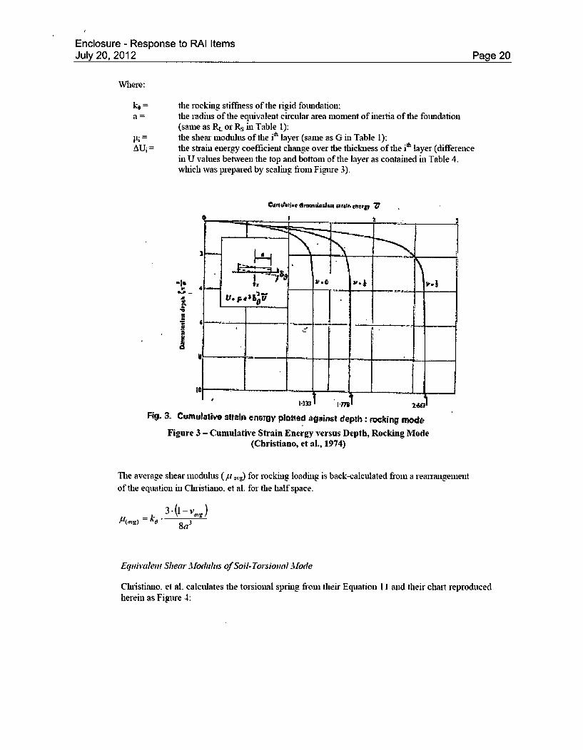
Cluistiano, et al. calculates the rocking spring fi'om their Equation 10 and their chart reproducedherein as Figure 3:
ke2- -i , 3 ' *AU, " (Christiano. et al.. Equation 10)
Enclosure - Response to RAI ItemsJuly 20, 2012 Page 20
Where:
ke = the rocking stiffness of the rigid foundation:a = the radius of the equivalent circular area moment of inertia of the foundation
(same as RE or Rs in Table 1):Ili = the shear modulus of the i' layer (same as G in Table 1):AUi = the strain energy coefficient change over the thickness of the i'h layer (difference
in U values between the top and bottom of the layer as contained in Table 4.which was prepared by scaling filom Figpre 3).
~ji~AatJ.e 4~mauLa4au 4r41h cftt~
-li
H
I
Fig. 3. Cumulative 911alti enwagy platled agaiint depth: romcking mod&
Figure 3 - Cumulative Strain Energy versus Depth, Rocking Mode(Christiono, et al., 1974)
The average shear modulus (p .,,,) for rocking loading is back-calculated from a rearrangementof the equation in Chiistiano. et al. for the half space.
3.- (I - j8a3
Equivalent Shear Modlthis of Soil-Torsional M11ode
Chiistiano. et al. calculates the torsional spring fiom their Equation 11 and their chart reproducedherein as Figure 4:

Enclosure - Response to RAI ItemsJuly 20, 2012 Page 21
12L83 *U (Christiano. et al.. Equation 11)
Where:
k= the torsional stiffness of the rigid foundation:a = the radius of the equivalent circular polar moment of inertia of the foundation
(same as R, in Table 1):li= the shear modulus of the idi layer (same as G in Table 1):
AUi = the strain energy coefficient change over the thickness of die it4 layer (differencein U values between the top and bottom of the layer as contained in Table 5.which was prepared by scaling from Figure 4).
ic
A
Il . i 4u;,
Fig. 4. Cumulative tr~ BflSnergy plotted against depth: twsting made
Figure 4 - Cumulative Strain Energy versus Depth, Torsional Mode(Christiano, et al., 1974)
The average shear modulus (LI ,- for torsional loading is back-calculated from a rearrangement
of the equation in Christiano, et al. for the half space.
3= •16a 3
b) The procedures used for the seismic analysis of the PSW Building are described incalculation OSC-9230, "PSW Building Structural Analysis," Rev.0. The Finite ElementAnalysis (FEA) is used to determine maximum design forces of various structuralcomponents of the PSW building and maximum foundation soil bearing stresses due tospecified loading conditions. A total of five (5) three-dimensional (3-D) FEA models aredeveloped using STAAD-PRO software package. The models consist of 4-noded plate

Enclosure - Response to RAI ItemsJuly 20, 2012 Page 22
(shell) elements with 6 Degrees Of Freedom (DOF)/node, 2-noded beam elements with6 DOF/node, and vertical and horizontal elastic springs representing Soil-StructureInteraction (SSI) characteristics.
The Safe Shutdown Earthquake (SSE) horizontal and vertical site specific designresponse spectra (5% damping ratio) of the PSW Building are determined in calculationOSC-9227, "Report of Geotechnical Exploration for Protected Service Water System andNatural Phenomenon Barrier System Projects", Rev. 0. According to specification OSS-027B.00-00-0002, "Seismic Displacements and Response Spectra for the Turbine,Auxiliary, Reactor and Standby Shutdown Facility Building," Rev. 8, the horizontal andvertical design spectra values for Operating Basis Earthquake (OBE) can be consideredas one-half (1/2) of the corresponding SSE horizontal and vertical design responsespectra values.
The PSW building SSE and OBE design response spectra (5% damping ratio) havebeen used as seismic input motion to perform dynamic linear response-spectrumanalysis in order to determine maximum seismic response of PSW Building in threeorthogonal directions X, Y, and Z (N-S, Vertical, and E-W, respectively).
The ONS is a two-directional earthquake motion plant according to UFSAR, Section3.7.2.5. Therefore, the PSW building has been analyzed for the maximum horizontalcomponent (either X or Z) and vertical component (Y) of earthquake appliedsimultaneously.
In other words, the maximum horizontal response spectrum (either X or Z) and verticalresponse spectrum (Y) are placed at the same load case and applied together to thePSW building FE model. Then modal responses are combined based on the CompleteQuadratic Combination (CQC) method to determine maximum response for eachseismic loading condition.
Four (4) FEA models are used in the seismic analysis of the PSW building. Thesemodels are identical with different seismic loading conditions. The seismic loadingconditions for these models are as follows:
- OBE design spectra applied horizontal N-S and vertical directions- OBE design spectra applied horizontal E-W and vertical directions- SSE design spectra applied horizontal N-S and vertical directions- SSE design spectra applied horizontal E-W and vertical directions
A fifth model is used for the Quasi-static linear analysis to determine the PSW structureresponse due to tornado generated wind pressure, missile impacts, and differentialpressure loads, in addition to dead and live loads.
The first 60 modes of vibration were considered in the linear dynamic response-spectrum analyses that included more than 97% of total structural mass for all threeorthogonal directions (X, Y, and Z) in seismic analysis (OSC-9230, Appendix B).
After performing the linear dynamic response-spectrum analyses for the four (4) seismicmodels and static analysis for the fifth model, then maximum responses of elements ineach finite element model are linearly added according to load combinations presentedin the calculation OSC-9230, Section 7.2 to determine maximum response of differentstructural components. The final forces for various structural components are presentedin OSC-9230, Sections 9.2 and 9.3. No load combinations produced uplift. Accidentaltorsion was not explicitly considered in the analyses due to the behavior of the modelunder seismic load combinations. Under seismic load combinations the motion of the

Enclosure - Response to RAI ItemsJuly 20, 2012 Page 23
PSW Building is such that the inherent eccentricity between the center of mass and thecenter of rigidity remains practically unchanged. In addition, all significant equipmentloads were accounted for and accurately located in the model. Moreover, there is aminimum of twenty percent (20%) reserve capacity in the structural componentsresisting seismic force.
The developed finite element models and performed dynamic linear response-spectrumanalyses are consistent with SRP 3.7.1 and SRP 3.7.2 requirements. There is nodifference in approaches/requirements for seismic analysis presented in SRP 3.7.1 andSRP 3.7.2 versus those used for the PSW building seismic analysis. Therefore, the PSWbuilding is adequately designed to withstand the effects of earthquake loads based onrequirements of SRP 3.7.1 and SRP 3.7.2.
The PSW building In-Structure response spectra development is presented in calculationOSC-9506, "Generation of SSE In-Structure Seismic Response Spectra for the PSWBuilding," Rev. 0. For the PSW building In-Structure response spectra development,linear dynamic time-history analyses of the PSW building have been performed usingartificial time history records as seismic input motion.
This calculation follows the requirements of Regulatory Guide 1.122, SRP 3.7.1, SRP3.7.2 and ASCE 4-98 for the artificial time history record development. The generatedtime history records in each direction satisfied four (4) characteristic requirementspresented in ASCE 4-98, Section 2.3. The developed time-history records satisfiedASCE 4-98 requirements as shown in OSC-9506, Section 6.1.
The SIMQKE software has been used to develop time history record in accordance withASCE 4-98 criteria.
One set of time history record is developed using SSE site specific design responsespectra that includes three statistically independent components of earthquake motion(i.e., three orthogonal time-history acceleration versus time records).
The SIMQKE software is approved for use in the analysis of nuclear safety-relatedstructures. Three statistically independent time history records have been developed forthe three defined orthogonal directions X, Y and Z.
The materials damping have been used in dynamic time-history analysis of the PSWBuilding that contain soil-structure interaction. A steel framing damping value of 2% anda reinforced concrete damping value of 5% for the SSE have been used in dynamicanalysis of the PSW Building in accordance with the ONS UFSAR Section 3.7.1.3.Theaverage soil damping value of 72% has been used in time-history dynamic analyses ofthe PSW Building. Soil damping determination is presented in calculation OSC-9506,Section 6.2.
A 3-D FEA model of the PSW building has been developed that include soil-structureinteraction. The developed model has been used for time-history dynamic analysesusing STAAD-PRO software. The time-history dynamic analysis method has been usedto determine time history response of selected nodes at the PSW Building using twoorthogonal time history records that apply to the base of the PSW building. The PSWbuilding has been analyzed using artificial time-history records, one in the horizontaldirection and one in the vertical direction that are applied simultaneously according tothe UFSAR, Section 3.7.2.5. Therefore, two dynamic analyses of the PSW building havebeen performed.

Enclosure - Response to RAI ItemsJuly 20, 2012 Page 24
The natural frequencies used in the dynamic analyses incorporate the lowest 60 modesat which approximately 97% of the PSW building participating mass are included for alldirections (OSC-9506, Table 6.2). Therefore, including higher modes in the dynamicanalyses would have had negligible effect on the developed floor response spectra.
The first analysis has been performed using horizontal time history record in X-direction(N-S) plus vertical time history record in Y-direction acting simultaneously. Similarly, thesecond analysis has been done using horizontal time history record in Z-direction (E-W)plus vertical time history record in Y-direction acting simultaneously.
Results are in the form of time history response of each of the fifteen (15) selectedlocations. A total of 38692 data points/location/direction) are then input to the RSG V2software to generate corresponding floor response spectra (FRS). The RSG V2 softwarehas been used to generate SSE horizontal and vertical FRS for fifteen (15) selectedlocations (points) using time history response of these selected points. The RSG V2software is approved software for use in the analysis of nuclear safety-related structures.
The developed SSE horizontal and vertical FRS are broadened (+/-) 15% in accordancewith ASCE 4-98, Section 3.4.2.3. RSG V2 software has been used for peak broadening.There are four broadened floor spectra for each selected point. They are horizontal X-direction (N-S), horizontal Z-direction (E-W), and two vertical Y-direction spectra. Twovertical Y-direction spectra are result of two seismic analyses for "N-S & Vertical" and "E-W & Vertical" FEA models.
The broadened SSE horizontal floor response spectra in X (N-S) and Z (E-W) directionsare enveloped at each selected point to determine the corresponding horizontal SSEfloor design spectra (FDS) that can be applied in any horizontal direction.
Similarly, the two broadened SSE vertical floor response spectra are enveloped at eachselected point to determine the corresponding SSE vertical floor design spectra. RSG V2software has been used for enveloping spectra. The enveloping process results in thedevelopment of one horizontal and one vertical SSE floor design spectra for each one ofthe selected points. Therefore a total of thirty (30) FDS are developed for the fifteen (15)selected locations of the PSW building.
In addition, horizontal FRS in N-S direction are enveloped for all selected points in eachelevation to develop one horizontal N-S SSE FDS for operating floor, battery room roof,external walls, and PSW building roof. This process is performed for horizontal FRS inE-W direction to develop one horizontal E-W SSE FDS for the same elevations.
Finally, horizontal and vertical FDS are enveloped for all selected points in eachelevation to develop one horizontal and one vertical SSE FDS for operating floor, batteryroom roof, external walls, and PSW building roof.
The horizontal and vertical floor design spectra for OBE can be determined using thedeveloped floor design spectra for SSE in accordance with Specification OSS-027B.00-00-0002, Rev. 8. This specification defines floor design spectrum values of the OBE asone-half (1/2) of the corresponding SSE values in horizontal and vertical directions.
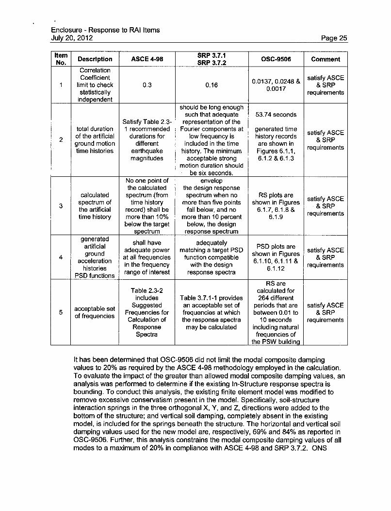
The methodology and approached used in the PSW building In-Structure responsespectra development is consistent with RG 1.122, SRP 3.7.1, SRP 3.7.2 and ASCE 4-98requirements. Therefore, the PSW building generated In-Structure response spectra areacceptable and comply with NRC requirements. See the table below for a reconciliationof the applicable provisions of ASCE 4-98, SRP 3.7.1, SRP 3.7.2, and OSC-9506.
Enclosure - Response to RAI ItemsJuly 20, 2012 Page 25
Item Description ASCE 4-98 SRP 3.7.1 OSC-9506 CommentNo. _______ SRP 3.7.2 OC90 omn
CorrelationCoefficient 0.0137, 0.0248 & satisfy ASCE
limit to check 0.3 0.16 & SRPstatistically 0.0017 requirements
independentshould be long enough
such that adequate 53.74 secondsSatisfy Table 2.3- representation of the
total duration 1 recommended Fourier components at generated time satisfy ASCE2 of the artificial durations for low frequency is history records & SRP
ground motion different included in the time are shown in requirementstime histories earthquake history. The minimum Figures 6.1.1,
magnitudes acceptable strong 6.1.2 & 6.1.3motion duration should
be six seconds.No one point of envelopthe calculated the design response
calculated spectrum (from spectrum when no RS plots are satisfy ASCE3 spectrum of time history more than five points shown in Figures & SRP
the artificial record) shall be fall below, and no 6.1.7, 6.1.8 & requirementstime history more than 10% more than 10 percent 6.1.9
below the target below, the designspectrum response spectrum
generated shall have adequately PSO plots aregrouna adequate power matching a target PSD shown i re satisfy ASCE
4 gron at all frequencies function compatible & SRPhistories in the frequency with the design 6.1.10, 6.1.11 & requirementsacceleration ~~~6.106.1.112 euieetPSD functions range of interest response spectra 6.1.12
RS areTable 2.3-2 calculated for
includes Table 3.7.1-1 provides 264 different
acceptable set Suggested an acceptable set of periods that are satisfy ASCE5 accenies Frequencies for frequencies at which between 0.01 to & SRP
of frequencies Calculation of the response spectra 10 seconds requirements
Response may be calculated including naturalSpectra frequencies of
the PSW building
It has been determined that OSC-9506 did not limit the modal composite dampingvalues to 20% as required by the ASCE 4-98 methodology employed in the calculation.To evaluate the impact of the greater than allowed modal composite damping values, ananalysis was performed to determine if the existing In-Structure response spectra isbounding. To conduct this analysis, the existing finite element model was modified toremove excessive conservatism present in the model. Specifically, soil-structureinteraction springs in the three orthogonal X, Y, and Z, directions were added to thebottom of the structure; and vertical soil damping, completely absent in the existingmodel, is included for the springs beneath the structure. The horizontal and vertical soildamping values used for the new model are, respectively, 69% and 84% as reported inOSC-9506. Further, this analysis constrains the modal composite damping values of allmodes to a maximum of 20% in compliance with ASCE 4-98 and SRP 3.7.2. ONS

Enclosure - Response to RAI ItemsJuly 20, 2012 Page 26
calculation OSC-9506 will be revised and the new results compared with the previousresults and any impact will be evaluated.
c) STAAD-PRO 2004 was used for the PSW building finite element modeling and analyses(see OSC-9230). The PSW In-Structure Response Spectra was developed after thePSW building analysis and design. At the time the In-Structure Response Spectra wasdeveloped the newer version, STAAD-PRO 2007, was available and was utilized.
Both the STAAD-PRO 2004 and STAAD-PRO 2007 FEA software were purchasedcommercial grade and were subjected to acceptance testing (validation) in accordancewith Sargent & Lundy Standard Operating Procedure SOP-0204, the requirements ofwhich are based upon ASME NQA-1 -1994, Subpart 2.7.
SOP-0204, governing all software validation and verification (V&V) regardless of itsintended use, is based on the requirements of Sargent & Lundy's Nuclear QA ProgramTopical Report, SL-TR-1A, including its commitment to the pertinent sections of ASMENQA-1-1994. The granting of "0" (Operational) status to any application at Sargent &Lundy, by definition per SOP-0204, means that it has been validated in accordance withthe SOP and is therefore suitable for nuclear safety-related applications.
d) ONS is a two directional earthquake motion plant according to UFSAR, Section 3.7.2.5.Therefore, PSW building has been analyzed for the maximum horizontal component(either X or Z) and vertical component (Y) of earthquake that is applied simultaneously. Itmeans that dynamic linear analyses of the PSW building consider two spatialcomponents of earthquake motion simultaneously that is consistent with the ONSUFSAR.
The modal responses used in the PSW building dynamic linear response-spectrumanalyses are combined based on complete quadratic combination (CQC) method. TheSTAAD- PRO seismic models are developed for linear response-spectrum analysis ofthe PSW building as it is explained in OSC-9230, Sheets 4 and 9. The two spatialcomponents of earthquake motion (E-W & Vertical or N-S & Vertical) are applied to thePSW building simultaneously and the responses are combined based on CQCmethodology utilizing STAAD-PRO software.
The CQC is an acceptable method of modal response combination as it is described inNRC Regulatory Guide (RG) 1.92, section C.1.1. Therefore, there is no difference inmodal responses combination between NRC RG 1.92 described methods with themethod utilized in PSW building linear dynamic analyses. Hence, the PSW buildinglinear dynamic analyses comply with RG 1.92 requirement; therefore, the PSW buildingis adequately designed to withstand the effects of earthquake loads.
For PSW building floor response spectra development, The STAAD-PRO FEA modelsdeveloped in OSC-9506 calculation and the dynamic linear time-history analysis isperformed to get time-history response of each node. The two statistically independentartificial time-history records (one horizontal and one vertical) are applied to the PSWbuilding finite element models as seismic input motions. It is acceptable methodology touse two statistical independent spatial components of earthquake motion simultaneouslyto get combined effects for dynamic linear time-history analyses as the ONS is a twodirectional plant according to UFSAR Section 3.7.2.5.
Therefore, two FEA models are developed for linear time-history analyses including onefor seismic input motion in N-S and vertical directions (X &Y) and one for seismic input

Enclosure - Response to RAI ItemsJuly 20, 2012 Page 27
motion in E-W and vertical directions (Z &Y). These input files are presented in OSC-9506 calculation, Appendix J and K.
The utilized methodology in the PSW building time-history analyses is consistent withNRC RG 1.92 methodology and also it agrees with method described in ASCE 4-98,Section 3.2.7.2 (a); therefore, the PSW building generated floor response spectra isacceptable and comply with NRC requirement.
RAI 142 [EMCB9]
The ONS UFSAR mark-up, included in the licensee's letter dated March 16, 2012, includesAmerican National Standard Institute (ANSI), American Institute of Steel Construction (AISC)N690-1984, and American Concrete Institute (ACI) 349-97, as the design codes for the PSWbuilding structural steel and reinforced concrete elements, respectively.
The current RG 1.142 (revision 2) endorses ACI 349-97 with exceptions. The SRP 3.8.4references the 1994 edition of ANSI/AISC N690 including Supplement 2 (2004) for the design ofsafety-related steel structures. Provide discussion and further information relative to thefollowing:
a) Demonstrate compliance with the provisions of the 1994 edition of ANSI/AISC N690including Supplement 2 (2004) or identify the differences between two editions andprovide a reconciliation to demonstrate the acceptability of using ANSI/AISCN6901984.
b) Confirm that ACI 349-97 have been followed in its entirety, where applicable, and allapplicable regulatory positions in RG 1.142 have been incorporated in the designand construction of the PSW building.
Duke Energy Response:
a) SRP 3.8.4, Revision 2, was published in March 2007. The PSW project was initiated in2006 utilizing SRP 3.8.4, DRAFT Revision 2, which endorses the use of ANSI/AISCN690-1984. This version of the N690 code was applied to the design of the new PSWStructures, as supplemented by Appendix F of SRP 3.8.4 DRAFT Revision 2.
b) ACI 349-97 was used for the design of new concrete structures (including the PSWBuilding, Manholes, and Ductbanks) as supplemented by Regulatory Guide 1.142,Revision 2. Anchorage of items within these structures was designed in accordance withACI 349-01, Appendix B, as supplemented by Regulatory Guide 1.199, Revision 0.Members subjected to torsion or combined shear/torsion were designed in accordancewith ACI 318-99, Section 11.6, as stated in Regulatory Position 15 of Regulatory Guide1.142, Revision 2.
(Note: Governing load combinations are the same as those presented in ACI 349-97 assupplemented by RG 1.142 as they are in SRP 3.8.4. The load factors presented in SRP3.8.4 in some instances exceed those within ACI 349-97/RG 1.142 for load cases whichdo not govern the design of the PSW Building. In either case the enveloping loadcombination is used (The same applies for ANSI/AISC N690-1984 vs. SRP 3.8.4). TheStrength Design Method was used for concrete and Allowable Stress Design was usedfor steel. Separate load combinations were used for the analysis of steel and concrete.)

Enclosure - Response to RAI ItemsJuly 20, 2012 Page 28
RAI 144 [EMCB9]
The ONS UFSAR mark-up, included in the licensee's letter dated March 16, 2012, describes theunderground conduit duct banks associated with the PSW building. It specifically states that asecond reinforced concrete duct bank/elevated raceway connects the PSW building to the Unit3 auxiliary building. It also states that these structures are seismically qualified to the maximumhypothetical earthquake and designed to withstand missiles, wind and differential pressureassociated with a tornado event.
Provide further information relative to the following:
a) The structural design criteria used for the design of the reinforced concrete duct banksand demonstrate compliance with Section 3.1.2 of the ONS UFSAR;
b) The procedures used for the analysis and design of the reinforced concrete duct banksfor seismic and tornado missile load conditions and confirm that these duct banks havebeen designed for the relative movement at the locations where they enter and exit therespective structures; and
c) The method of protection against tornado wind and tornado missiles for the elevated(above ground) electrical raceway connecting the PSW building to the Unit 3 auxiliarybuilding.
Duke Energy Response:
a) The PSW Ductbanks and related structures are designed for Natural Phenomena asspecified in the UFSAR Section 3.1.2. Load combinations and structural design criteriaare given in ONS specification OSS-0292.00-00-0001, Specification for Design andImplementation Support of the Protected Service Water System, Revision 2. (Note: ThePSW system is not credited for mitigation of station damage from turbine missiles;therefore, turbine missiles are not considered in the design of PSW structures, systems,or components.)
Load Combinations
Load Combinations which govern the design of the PSW Ductbank are as specified inNUREG-0800, SRP 3.8.4, DRAFT Revision 2, ACI 349-97 as supplemented byRegulatory Guide 1.142, and ANSI/AISC N690-1984 as supplemented by Appendix F ofSRP Section 3.8.4.
(Note: Governing load combinations are the same as those presented in ACI 349-97 assupplemented by RG 1.142 as they are in SRP 3.8.4. The load factors presented in SRP3.8.4 in some instances exceed those within ACI 349-97/RG 1.142 for load cases whichdo not govern the design of the PSW Ductbank. In either case the enveloping loadcombination is used. (The same applies for ANSI/AISC N690-1984 vs. SRP 3.8.4) TheStrength Design Method was used for concrete and Allowable Stress Design was usedfor steel. Separate load combinations were used for the analysis of steel and concrete.)

Enclosure - Response to RAI ItemsJuly 20, 2012 Page 29
Structural Design Criteria
Loads
- Dead loads consist of the weight of the structure plus all equipment and materialspermanently fastened to, and supported by, the structure/component.
- Live loads are the loads produced by the use and occupancy of the ductbank.They include the weight of all movable loads, including personnel, tools,miscellaneous equipment and stored material. Areas subjected to roadway loadsare designed for two American Association of State Highway and TransportationOfficials (AASHTO) HS20 trucks passing simultaneously and Reactor CoolantPump Motor transport trailer loadings.
- The design wind velocity is 95 mph. The applied wind pressures are computedby the means outlined in ASCE Paper No. 3269 which states that the equivalentstatic force on the building is equal to the dynamic pressure (q) times the dragcoefficient (Cd) multiplied by the elevation area. (Oconee UFSAR Section 3.3.1)
- Seismic design response spectra as specified in Section 3.7.1.1 of the OconeeUFSAR. Critical damping values as specified in Section 3.7.1.3 of the OconeeUFSAR. Components of earthquake motion applied as specified in Section3.7.2.5 of the Oconee UFSAR.
- Tornado loadings conform to Regulatory Guide 1.76, Revision 1.
Codes and Standards
- Concrete: Subsection C of Regulatory Guide 1.142, Revision 2 (i.e., ACI 349-97(except for Appendix B) as supplemented by Regulatory Guide 1.142 andsupplemented by Regulatory Guide 1.199, November 2003)
- Structural steel and plates: Subsection 11.2 of Standard Review Plan (SRP)Section 3.8.4, DRAFT Revision 2 (i.e., ANSI/AISC N690-1984 as supplementedby Appendix F of SRP Section 3.8.4)
- Anchoring components and structural supports in concrete: Subsection C ofRegulatory Guide 1.199 (i.e., Appendix B (February 2001) to ACI 349-01 assupplemented by Regulatory Guide 1.199)
- Foundations: Subsection 11.3 of SRP Section 3.8.5, Subsection 11.4.a of SRPSection 3.8.5, DRAFT Revision 2 (including SRP Section 3.7.2, DRAFT Revision3 methods for combining three components of earthquake to computeoverturning moment), Subsection 11.5 of SRP Section 3.8.5, and NUREG/CR-6896, February 2006.
- Structural acceptance criteria: Subsection 11.5 of SRP Section 3.8.4, DRAFTRevision 2.
b) Structural analysis and design of the reinforced concrete ductbanks, manholes andassociated structural steel utilized a combination of hand calculations and Finite ElementAnalysis (FEA). Beam on Elastic Foundation analysis used conservative values for soilsprings that yielded an upper bound of maximum forces on critical sections.Reinforcement required for critical sections was conservatively continued through thelength of the reinforced concrete ductbank. The governing load cases for the design ofthe ductbank were tornado missile load combinations, except for lateral loads of belowgrade ductbanks. For lateral loads of below grade ductbanks, the SSE load combinationgoverned and conservative analysis included applying mass inertial forces to the

Enclosure - Response to RAI ItemsJuly 20, 2012 Page 30
ductbank without accounting for soil friction to resist lateral loads. This methodology isconservative in comparison to the methodology presented in ASCE 4-98 Section 3.5.2.
Ductbanks were analyzed for direct vertical missile impacts and soil cover was notincluded in the analysis to resist vertical missile strikes. Horizontal missiles were notincluded in the analysis for below grade ductbanks, but were included in the abovegrade ductbank analyses as direct strikes without any side soil cover to resist missilestrikes.
New structures were analyzed to resist the shears and moments applied by theductbanks and connections were analyzed for rigidity to ensure no differentialmovements would occur between structures. End connection details for the ductbanks atnew structures include embedment of bent reinforcement into adjacent structures for asemi-rigid connection. Concrete placement was monolithic between walls of adjacentstructures and sufficient tributary length of the ductbank to ensure adequate shearcapacity was developed.
To isolate the PSW Ductbank structures from existing structures (i.e. Auxiliary Building,SSF Building/Trenches and existing Keowee trenches) a flexible connection was utilizedto allow deflection under the design loads while still precluding water intrusion. Ananalysis to determine the deflection of the structures under the load combinations listedin part (a) above was compared to the gap provided by the flexible design to ensureaccommodation of the expected deflections without applying loads to theconduits/cables housed within these structures.
(Note: fc' = 5,000 psi and fy = 60,000 psi for reinforced concrete design)
c) The above ground electrical raceway is a steel frame and plate structure that connectsManhole 7 (MH7) to the Technical Support Building (TSB) underground vault and spansabove ground between the two structures. (Reference drawings 0-398-Al-213 and 214)and contains safety related cable supported in cable trays. This structure is designedusing the structural design criteria applied to the entire ductbank system, and asdescribed in part (a) above. The raceway is rigidly connected to MH7 and the TSB Vaultutilizing sixteen (16) embedded anchors at MH7 and TSB Cable Vault (eight (8) eachwall of each structure). MH7, the TSB Cable Vault, the Overhead Cable Raceway, andanchorage between the three structures are all designed for worst case loads which mayresult from any of the applied loads on the structures. FEA models of each of thesestructures were developed congruently to ensure that no structure or connection will failduring a design basis event.
RAI 145 [EMCB10]
Provide further information relative to the evaluation of the existing underground commodities (ifany) for the additional loads exerted by the PSW building foundation footprint to demonstratethat there will be no adverse effects on the existing underground utilities for all applicable designloading conditions.
Duke Energy Response:
Engineering change package EC 91832, "Underground Commodity Relocation," addressed theexisting underground commodities within the PSW Building footprint. These commoditiesidentified on drawing 0-398-Al-302, "PSW Building, Underground Utility Composite Plan, Areaof PSW Building," Revision B, are: an abandoned air pipe, Radwaste Facility sewer pipe,

Enclosure - Response to RAI ItemsJuly 20, 2012 Page 31
existing catch basins and storm sewer (yard drain) pipes. Drawing 0-398-Al-301, "PSWBuilding, Underground Utility Demolition Plan, Area of PSW Building," Revision A indicates theextent of demolition and drawing 0-398-Al-303, "PSW Building, Enlarged Underground UtilityPlan," Revision A, shows the commodity re-routing.
The abandoned air pipe was cut and capped at each end outside the PSW Building footprint toremove it from the extent of construction. The Radwaste Facility sewer pipe was cut andrelocated outside the PSW Building footprint to the west and north sides of the PSW Building.The catch basins and storm sewer (yard drain) pipes were demolished within and around thePSW Building footprint and replaced with new catch basins and storm sewer (yard drain) pipes.The new storm sewer (yard drain) system of catch basins and pipes is located to the west andeast of the PSW Building, except for one new 15-inch diameter storm sewer (yard drain) pipe.This pipe connects new catch basin CB #1000 on the west side and existing Manhole 2 (MH2),on the east side of the PSW Building. This storm sewer (yard drain) pipe, at its highest point,has an invert elevation 2'-9" below the bottom of the PSW Building foundation and is encased inconcrete. There is no interface between the new 15" storm sewer pipe and the PSW Buildingbelow grade walls. Refer to drawings 0-398-Al-304, "PSW Building, Underground Utility &Catch Basin Sections & Details," Revision A, and 0-398-A2-401, "PSW Building, ElevationSections & Details," Revision E. Therefore, the only commodity under the PSW Buildingfoundation is the one new storm sewer line that is adequately protected by soil cover andconcrete encasement from any adverse effects of PSW Building foundation loads.
RAI 147 [EMCB12]
Provide further information relative to the procedures used in calculating the dynamic lateral soilpressure for the design of below grade walls of the PSW building.
Duke Energy Response:
PSW Building external walls (below and above grade) are designed with the samereinforcement size and spacing from foundation level to roof. The horizontal tornado wind andmissile impact load combination governs the design of the external walls above and belowgrade. The generated pressure due to horizontal tornado missile impact (298 kips load appliedto 34.5 in2 area) is much higher, by inspection, than dynamic lateral soil passive pressure.Therefore, the entire wall design governing load combination is bounded by the horizontaltornado wind and missile impact load combination.
In summary, the entire wall is designed based on the horizontal tornado wind and missile impactload combination that is much higher than dynamic lateral soil pressure load combination.Therefore, walls below grade can withstand dynamic lateral soil passive pressure.
RAI 148 [EMCB13]
Provide further information whether there are any existing SSCs, in the vicinity of the PSWbuilding, that could have an adverse interaction with the PSW building.
Duke Energy Response:
There are three major SSCs in the vicinity of the PSW building that could have an adverseinteraction with the PSW building. These SSCs are the "RCP Motor Refurbishment Facility,""Radwaste Facility" and the underground "CCW Piping System."

Enclosure - Response to RAI ItemsJuly 20, 2012 Page 32
The effects of the "Reactor Coolant Pump (RCP) Motor Refurbishment Facility" and "RadwasteFacility" (RWF) on the PSW building integrity has been evaluated in calculation OSC-9230"PSW Building Structural Analysis," Revision 0, Section 12.0. It is determined that failure of the"RCP Motor Refurbishment Facility" and "Radwaste Facility" during a seismic event would affectneither structural integrity, nor operability of the PSW Building during and after the seismicevent.
The RCP Motor Refurbishment Facility is separated by adequate space, approximately 80', toprevent any adverse seismic interaction.
The RWF is a large, relatively low building (approximately 200 ft length x 140 ft width x 50 ftmaximum height, 30 ft height adjacent to PSW Building) that is supported by a minimum 3 ftthick reinforced concrete foundation. Overturning of this structure is not considered a crediblescenario during an SSE event.
The maximum load capacity ratio of RWF structural components is 0.8 under OBE seismic loadcombination. The reserve capacity of the structural components is available to resist theadditional loading of an SSE event prior to the onset of localized failure mechanism formation.Complete global failure of the RWF superstructure during an SSE event is not considered acredible scenario. In the unlikely scenario of significant localized failures of RWF structuralcomponents adjacent to the PSW building the debris from such failures will not have an adverseimpact on the structural integrity or operability of the PSW Building due to its own reservestructural capacity to withstand an SSE event (see OSC-9230, Revision 0, Section 12.0).
The Condenser Circulating Water (CCW) Piping System is located underground parallel to thePSW building east external wall. Concrete fill was placed adjacent to the CCW pipes andbeneath the PSW Building foundation from elevation 788'-3," bottom of PSW footing, toapproximate elevation 778'-3," the bottom of the existing CCW foundation. This massiveconcrete fill ensures that both structures are founded on the same subgrade and there is noadverse seismic interaction between the PSW Building and the CCW Piping System (referencedrawing 0-398-Al-304).
RAI 160 [EMCB15]
In response to RAI-62, the licensee included, in its letter dated January 20, 2012, Institute ofElectrical and Electronic Engineers (IEEE) 344-1975 as one of the industry standards that isbeing used for the PSW system design. Discuss the seismic qualification method(s) used forelectrical and mechanical equipment credited for the PSW system. Provide a summary of theseismic qualification results to demonstrate that all equipment credited for the PSW systemincluding their subcomponents (relays, contacts, breakers etc.) are capable to perform theirintended design function in the event of a safe shutdown earthquake (SSE) after a number ofpostulated occurrences of the operating basis earthquake (OBE). The response to this RAI, as aminimum, should include the test response spectra (if applicable), the required responsespectra, the method of mounting of equipment to the shake table, and the equipment mountingconfiguration in service condition. Also, discuss the methodology, the industry codes andstandards, the level of earthquake, and the acceptance criteria used for the structural design ofthe PSW equipment mounting.
Duke Energy Response:
The Duke Energy response to this request for information has three parts: I) Seismicqualification of electrical equipment, II) seismic qualification of mechanical equipment and Ill)anchorage as discussed below.

Enclosure - Response to RAI ItemsJuly 20, 2012 Page 33
I. Seismic Qualification of Electrical Equipment
Seismic qualification of electrical equipment is outlined in Section 3.10 of the OconeeUpdated Final Safety Analysis Report (UFSAR). For the PSW project, QA-1 electricalequipment was seismically qualified in accordance with IEEE 344-1975, which meets orexceeds the Oconee UFSAR requirements for qualification by testing or analysis.Qualification is performed for all electrical equipment using shake table testing, analysis or acombination of testing and analysis.
The NRC endorsed IEEE 344-1975, with exceptions, in Regulatory Guide 1.100, Revision 1.The exceptions were:
1) Section 5.3 - Use of the 1.5 static coefficient was found acceptable but arequirement was imposed for justifying its use.
2) Section 6.6.2.1 - This concerns single-frequency test input motion and that theresultant Test Response Spectrum (TRS) at the test frequencies must equal 1.5times the acceleration of the required response spectrum (RRS). This section alsoallowed the TRS to not envelope the RRS, if the 1.5 factor was used. Justificationis therefore required to use single frequency testing and for the TRS to notenvelope the RRS.
3) Section 6.6.2.5 - For sine sweep testing, the TRS was again allowed to fall belowthe RRS by reference to Section 6.6.2.1. Sine sweep testing was deemed notsuitable for equipment qualification unless justification was provided.
4) Section 8 - Documentation. Supplemental documentation is required related toequipment malfunction data.
For QA-1 electrical equipment, procurement documents were generated in accordance withDuke Energy's directive EDM-140 "Procurement Specifications for Equipment." Seismicdemand at the equipment mounting location was included in those procurementdocuments. For new floor- and wall-mounted electrical enclosures, the applicable in-structure response spectra demand was used for the equipment mounting location. Forcomponents added to existing safety-related electrical enclosures, such as the electricalcomponents added to the Oconee Main Control Boards, in-cabinet response spectrademand for the electrical component mounting locations was specified.
Procurement documents were used by the selected vendors to perform the qualification.Whether testing, analysis or a combination of testing and analysis was used; the vendorsassured the resulting seismic capacity of the equipment enveloped the specified seismicdemand. For testing, the 10% margin specified in IEEE 323 was included. Pre- and post-seismic functional testing was performed. All shake table testing consisted of five OBEearthquakes followed by SSE testing taking into account the electrical safety function of theequipment (i.e. contactors were evaluated in energized and de-energized states and fortransition between those states and chatter was monitored in excess of 2 msec). Inaddition, random multi-frequency input was used for the testing as opposed to single-frequency and sine-sweep testing noted in the RG 1.100 exceptions #2 and #3 above. Anyanomalies found through testing were documented in the qualification reports and given adisposition. Therefore, RG 1.100, Revision 1 Exceptions #2, #3 and #4 were addressed.
Qualification by analysis was used for some of the equipment following the methods given inIEEE 344-1975. The 1.5 multimode factor was used as appropriate and justified.Therefore, RG 1.100, Revision 1 Exception #1 has been addressed.
As part of the procurement, Duke Energy required an owner review and approval of thequalification plans prior to the qualification to insure the vendor's qualification method would

Enclosure - Response to RAI ItemsJuly 20, 2012 Page 34
meet the owner's requirements. Vendor qualifications were documented in vendorqualification reports that were again owner reviewed. Final qualification reports wereentered into Oconee Document Control and Records Management to maintain a record ofthe qualification. Qualification reports met the documentation requirements of IEEE 344-1975 and included seismic capacity versus demand comparisons. Because of the extensivelist of electrical equipment, there is a corresponding extensive list of qualificationdocuments.
The procurement documents also required the vendor to determine anchoragerequirements. The qualifications documented the adequacy of that anchorage design andeach vendor developed drawings to transmit the anchorage design. The drawings wereused to anchor the equipment to the structures during implementation of the engineeringchanges. If problems arose with the vendor-defined anchorage, then site civil wascontacted and they worked with the vendor to determine the acceptability of any changes.
Appendix AW of ONS calculation OSC-9506, "Generation of SSE In-Structure SeismicResponse Spectra for the PSW Building," Revision 0, includes a figure on P. AW2 identifiedas PAW1 "Seismic Horizontal and Vertical FDS (5% Damping) and EPS, Elevation 818'."The purpose of that figure is to compare the final horizontal and vertical envelopes of the in-structure response spectra calculated for the center of the roof of the PSW Building againstthe conservative estimate of worst-case in-structure spectra referred to as "EquipmentProcurement Spectra" (EPS). It should be noted that the EPS was determined, and used forprocurement purposes for equipment with long lead-times, as the PSW Building responsespectra analyses were being performed. When the final enveloped results were created forthe operating floor, mezzanine, mid-height of the walls and the roof of the PSW Building,they were compared to the EPS in Appendices AT through AW. As shown in those plots,the EPS did indeed bound all of the PSW Building locations except for the vertical responseat the center of the PSW Building roof.
Wherever the EPS was used for the procurement of electrical equipment, the procurementspecifications included hold points to validate the seismic input(s). The hold points wereremoved by either revising the procurement specification to add the corresponding finalenvelopes from OSC-9506 or in some cases deviations to the procurement specificationswere issued with the corresponding final envelopes from OSC-9506. In either case, theequipment that was initially procured using the EPS was qualified using the appropriateseismic in-structure spectra.
Seismic Qualification of Electrical Equipment
Specific Example - Motor Control Centers in the PSW and Auxiliary Buildings
Motor Control Centers (MCC) were included with the scope of PSW electrical equipmentand are located in the Auxiliary and PSW Buildings. The requirements for procurement ofthe MCCs were documented in OSS-0308.00-00-0007, "Procurement Specification for theDesign, Fabrication and testing of the QA-1, 600 VAC Motor Control Centers (MCCs) for theProtected Service Water (PSW) System," Revision 2. Nuclear Logistics Incorporated (NLI)was selected as the supplier and their qualification plan was documented in QP-29412392-1, "Qualification Plan for Motor Control Centers," Revision 3. Duke Energy approved thatqualification plan and NLI performed the qualification. Seismic qualification of theequipment was documented in NLI Qualification Report QR-29412392-1, "QualificationReport for Motor Control Centers," Revision 4 which was filed as an Oconee vendor manualand placed in Oconee Document Control and Records Management. The vendor manual

Enclosure - Response to RAI ItemsJuly 20, 2012 Page 35
number is OM 308.--531.001, "PSW - Seismic Qualification Report for Motor ControlCenters XPSW, 1XPSW, 2XPSWA, 2XPSWB and 3XPSW," Revision 4.
The MCCs were qualified by a combination of shake table testing and analysis inaccordance with IEEE 344-1975. Shake table testing was used to qualify the enclosuresand equipment and analysis was used to qualify additional changes made after thecompletion of the shake table testing. For example, analysis was used to address verticalbarriers added to the enclosures for personnel safety.
The MCCs consist of two different types based on physical location: 1) NEMA 3R MCCs forthe Auxiliary Building and 2) NEMA 1 MCCs for the PSW Building. All of the MCCs wereFreedom 2100 Series with a 600A main bus and were joined in sets connected on theirsides. The largest sets have five sections bolted together and the smallest set has twosections bolted together.
One representative NEMA 1 enclosure was bolted to one representative NEMA 3Renclosure using the standard inter-cabinet bolting used for these enclosures. The boltedenclosure set was welded to a base plate to simulate the installed configuration in the finaldesign drawings. The as-tested layout is shown on NLI Drawing 29412392-LDTS-1, "MCCTest Specimen Outline," Revision 3 that is given in Appendix D of the NLI QualificationReport. The base plate containing the set of two enclosures was fastened to the shaketable using four 3/8" diameter bolts. The report states that four bolts used to anchor the setof two enclosures bounds the proposed field installation where four bolts were specified foreach individual section (i.e. a set of two sections has a total of eight anchors in the field).
Each enclosure specimen included a representative set of electrical equipment. Theequipment was selected by considering all of the equipment in all of the MCC enclosuresand the relative mounting locations of that equipment within the enclosure. Traceabilitybetween the test specimens and the production units was given in Section 2.2 of thequalification report.
In-structure response spectra for the Auxiliary and PSW Buildings were included in theprocurement specification. NLI created a composite envelope of those spectra and used itas the Required Response Spectra (RRS) input for the shake table testing. The OperatingBasis Earthquake (OBE) at Oconee is one-half the Safe Shutdown Earthquake (SSE) so theRRS was factored by 0.5 for the OBE and taken as the full value for the SSE.
A comparison of the Test Response Spectrum (TRS), obtained from the controlaccelerometers, to the RRS for the SSE is shown in Figures 160.1 and 160.2 for thehorizontal and vertical excitation directions respectively (Note: Figures 160.1 and 160.2 areprovided in the RAI #160 supplemental information section of the Attachment to this letter).
An anomaly documented the fact that the TRS did not fully envelope the RRS belowapproximately 2 Hz for both excitation directions. Before the OBE and SSE testing,however, the vendor performed low-level sine-sweeps to determine the resonantfrequencies of the enclosure set. Because the enclosure set did not have resonantfrequencies in that range, the exceedance was deemed acceptable.
The testing consisted of five OBE tests followed by three SSE tests that covered theenergized, de-energized and transition states of the electrical equipment. Two of the SSEtests were substituted for two of the OBE tests. The test series was conducted in fourdifferent specimen orientations at 0, 90, 180 and 270 degrees to capture the in-phase andout-of-phase response due to the dependent biaxial shake table.

Enclosure - Response to RAI ItemsJuly 20, 2012 Page 36
QA-1 electrical equipment was subjected to pre- and post-seismic functional testing and wasmonitored for contact chatter in excess of two milliseconds during the shake table testing.The list of equipment, functional state, type of monitoring and acceptance criteria was givenin Section 4.2.6 of the report for the three SSE tests. Equipment with no moving contacts(i.e. terminal blocks and fuse blocks) was monitored for continuity and non-safety equipmentwas evaluated for structural integrity (mounting) only. All of the equipment met theacceptance criteria except that the door on the NEMA 3R enclosure popped open duringsome of the testing. NLI resolved this issue by adding a small padlock to the door and thenlater qualified a hitch pin proposed by Duke Energy. The requirement to include the hitchpin to maintain seismic qualification was included on the final design drawings.
Anomalies were identified and addressed in an appendix to the test report.
Additional analysis was used to quantify anchorage loads to be used by Duke Energy. Thequalification report references a separate NLI anchorage qualification report. Theanchorage qualification report is QR-29411642-4, Revision 3 and was filed as an OconeeVendor Manual OM 302.A-0072.004, "Mounting Base Design and Anchorage Loads for NLISupplied Equipment," Revision 3.
Specific Example - Batteries and Battery Racks in the PSW Building
See Duke Energy's response to RAI-161 (submitted to the NRC on July 11, 2012) for thedetails of the qualification of the PSW batteries and racks.
I1. Seismic Qualification of Mechanical Equipment
Specification ECV-0601.00-00-0005, Revision1 "Specification for the Seismic Qualificationof Equipment" by Duke Energy Carolinas, LLC, Oconee Nuclear Station Units 1, 2 and 3describes acceptable methods for seismic qualification of electromechanical equipment.The following governing design criteria documents and references are used, among others,as a basis for the seismic qualification:
* UFSAR:
Section 3.7 "Seismic Design," Section 3.9 "Mechanical Systems and Components,"Section 3.10 "Seismic Qualification of Category I Instrumentation and ElectricalEquipment."
" Codes and Standards:
IEEE Standard 344-1975.IEEE Standard 323-1974.
" Specifications:
OSS -254.00-00-4010, "Design Basis Specification for Seismic Design," Revision 4.
* Regulatory Documents:
USAEC RegGuide 1.60, December, 1973.USAEC RegGuide 1.61, October, 1973.USNRC RegGuide 1.100, Revision 1.
As QA -1, the PSW mechanical equipment (ME) seismic qualification is governed by the QAprogram requirements of 10CFR50, Appendix B, and applicable ONS's procurement,design, fabrication, and installation specifications supplemented by industry codes,standards, and US NRC regulatory guides. Procurement specifications cover the design,fabrication, testing, delivery, and quality assurance documentation of the equipment.

Enclosure - Response to RAI ItemsJuly 20, 2012 Page 37
Seismic qualification of QA-1 equipment was treated as Class 1 E equipment and thereforeis governed by detailed requirements stipulated in IEEE Standards 344-1975 and IEEEStandards 323-1974.
IEEE Standards 344-1975 provide procedures which verify that Class 1-E equipment canmeet its performance requirements during and following one SSE preceded by five (5) OBEseismic events. Section 4 of IEEE 344 provides acceptable methods used for seismicqualification as follows:
I. Analysis that would predict equipment performance (safety margins against codeallowable for various operating and accident loading conditions).
2. Testing under simulated seismic conditions (for operability, and overall structuralintegrity determination).
3. Qualification by combined test and analysis.
Choice of qualification method is based on the type, size, shape, and complexity of theequipment and the desired reliability of the conclusion.
IEEE Standard 323-1974, Section 4, lists operating experience as a method of limited useas a sole means of seismic qualification but of great use for supplementation of testing. Inaddition, Section 6.3.1.5 lists margins (suggested factors) to be applied to service conditions(e.g., temperatures +150F, pressure +10% •10 psi, etc.).
For the ONS PSW Project, Mechanical Equipment procurement specifications were issuedto Duke Energy approved vendors. These specifications provided detailed seismicqualification requirements for the vendors to use. The following are examples ofqualification by analysis and testing.
Examples:
1. Seismic Qualification by Analysis
Equipment: Booster PumpSulzer Report No.: PVA1000294590010-01, Revision 3.
Procurement Specification:
Details seismic testing requirements for any PSW mechanical equipment are provided inpertinent procurement specification. Specification OSS-0208.00-00-0015, "ProtectedService Water Booster Pump," Revision 2 provides the following:
* Section 2.5 of the specification addresses seismic requirements. It refers toECV-0601.00-00-0005 for seismic conditions. This specification was generatedby Duke Energy; the response Spectra is provided in the Attachment for RAI#160.
* Section 6.0 addresses Quality Assurance requirements including documentation." Section 8.0 addresses supplier's documents.* Section 10: Test and Inspection." Section 14.0: Conformance with Specification.
Seismic Qualification Analysis:
Qualification Method:
The seismic qualification analysis of the PSW system Booster Pump was performedusing general purpose finite element code ANSYS. A three-dimensional (3-D) FiniteElement Model (FEM) detailing mass, stiffness, and bolted connections of various

Enclosure - Response to RAI ItemsJuly 20, 2012 Page 38
components of the pump, motor and mounting steel frame was developed. The modelincluded contact elements to simulate bolted connections preload conditions andpotential separation between contacted surfaces.
A natural frequency analysis was performed on the FEM and the results indicated that allcalculated natural frequencies were above the Zero Period Acceleration (ZPA) frequencyof 20 Hz. Accordingly, the pump assembly was, therefore, considered rigid andequivalent static analysis method was used to determine effects of OBE and SSEseismic loading conditions. The method includes the use of applicable ZPAaccelerations, a static coefficient of 1.5, and the square-root-sum-of squares (SRSS)method to combine seismic responses in the three orthogonal directions (2 horizontaland 1 vertical).
Loads:
The following loads are considered in the qualification of the pump assembly:
1) Seismic OBE and SSE2) Internal pressure3) Nozzle loading4) Dead weight5) Thermal6) Bolt pre-load
Summary of Results:
Following are Load/Capacity, (L/C) ratios (i.e., Calculated/ Allowable):
- Natural frequency: lowest frequency = 82 Hz > 20 Hz (ZPA):
System is rigid
- Pump/ Pressure Boundary Components:
Casing; L/C = 0.30 < 1.0 O.K.Cover; L/C = 0.35 < 1.0 O.K.Bearing Housing; L/C = 0.25 < 1.0 O.K.
- Bolting:
Case to Cover L/C = 0.50 < 1.0 O.K.Cover to Bearing Housing UC = 0.50 < 1.0 O.K.Cover to Seal Housing LJC = 0.50 < 1.0 O.K.Pump Hold-down L/C = 0.66 < 1.0 O.K.Base Plate (stress) L/C < 0.78 < 1.0 O.K.Base Plate (deflection) L/C = 0.35 < 1.0 O.K.Leakage;
No leakage into bolt-holes predicted O.K.
- Anchor Bolt Loads:
Case 1: Gravity + Nozzle Loads + Motor Short-CircuitCalculated maximum Tension and Shear forces are less than allowablevalues.
Case 2: Gravity + SSE Nozzle Loads + SSECalculated maximum Tension and Shear forces are less than allowablevalues.

Enclosure - Response to RAI ItemsJuly 20, 2012 Page 39
- Rotor Evaluation:
Lateral Displacement: During SSE seismic = 22% of clearance. No touchingAxial Thrust: During SSE seismic is negligible (< 1% of capacity)Coupling Deflection: During SSE seismic is negligible (= 1.7 % of allowable)
- Pipe Work:
Piping Stress: L/C = 0.29 < 1.0 O.K.Nozzle Loads; Acceptable based on piping stresses meeting ONSSpecification OS-027B-00-0001, Revision 8 requirements.
Flange Analysis: L/C = 0.09 < 1.0 O.K.
Based on the above results, the capacity, C, of the evaluated components (as specifiedby the pertinent allowable values) far exceeds the seismic demand (i.e., the calculatedload, L, values). Therefore, ample margins of safety exist against specified operatingand seismic load combinations.
Analysis Response Spectra:
Section 3.1 of Sulzer's seismic analysis report lists applicable OBE seismic responsespectra (RS) (where the Booster Pump will be mounted) for the Auxiliary Building, FloorEl. 771', N-S, E-W, and vertical directions. The applicable RS are provided inprocurement specification OSS-0208.00-00-0015, Revision 2 of the PSW Booster Pump.
2. Seismic Qualification by Testing
Equipment: Six inch (6") Velan forged bolted bonnet gate valves OM-245-2576, OM-245-2577 (DMV-1459, DMV-1 488); Velan Operability Test Report (Duke Energy FileNo.): OM 245-2582.001, Revision 1.
Applicable Specifications:
- OSS-0245.00-00-0004, "ASME Section III and Oconee Safety Related Class F, 2.5inch and larger, carbon and stainless gate, globe and check valves and operators(Duke Energy Class A, B, C and F) Revision 2.
- ECV-0601.00-00-0003, "Specification for Seismic Qualification of Valves for A.S.M.E.Section III and Duke Power safety Class F Applications," Revision 1.
- OSR-0245.00-00-0040, "Technical Requirements for Valve Numbers DMV-1459 andDMV-1488," Revision 1.
Seismic Qualification Test:
Qualification Method:
All active valves having extended structure such as actuators shall be functionally testedto ensure operability. While installed in a suitable test rig, the extended top works (i.e.,the actuator and the yoke) of the valve was statically deflected by a load greater than theequivalent seismic load of the SSE. The load was applied at the center of gravity of theoperator in the direction of the weakest axis of the yoke. Simultaneously, the designpressure of the valve was applied to the valve while in the closed position while thedownstream of the valve was at atmospheric pressure.
To test operability under simulated SSE seismic load, the valve was operated from theclosed position to the open position. The valve internal pressure was increased to the

Enclosure - Response to RAI ItemsJuly 20, 2012 Page 40
design pressure and the valve closed while still being statically deflected. The opening
and closing time was recorded, and checked against the specified operating time limits.
Loads:
- The subject valves are required to meet the acceleration values of 2.5g OBE and5.Og SSE in each of the three (3) orthogonal directions (specification ECV-0601.00-00-0003, Revision 1).
- The required test side load is F = 10 WThe test load is determined as follows:Resultant acceleration = [4(5.0 2 +5.02 +5.02)] g + 1 g (dead weight) = 9.66 gRound up to 10 gWhere:F = the minimum side load to be appliedW = weight of extended mass
Summary of Results:
- No permanent deformation of the extended structure was recorded.- The tested valves operated smoothly throughout the full open and close strokes with
or without the application of the equivalent SSE static side force and pressure.- Seat leakage did not exceed the specified limit of 2 ml (cc) per hour per inch of
nominal size, in 10 minutes.- The tested valves pressure boundary shells and packing did not leak.
I1l. Seismic Qualification of Anchorage
Load combinations and structural design criteria for anchorage of components in the PSW,Auxiliary, and SSF Buildings are given in ONS specification OSS-0292.00-00-0001,Specification for Design and Implementation Support of the Protected Service WaterSystem, for SSE and OBE earthquakes.
Methodolo-gy:
All Buildings
- Attachments are QA-1.- Seismic analysis of the attachment of electrical equipment uses a static coefficient
factor of 1.5 for new designs.- The design of concrete expansion anchors used to attach new and/or existing
equipment are in accordance with specifications OSS-0020.00-00-0004,Specification for the Design, Installation and Inspection of Concrete ExpansionAnchors, and OSS-0020.00-00-0006, Specification for the Design, Installation, andInspection of Hilti Concrete Expansion Anchors.
PSW Building and Auxiliary Buildings
- Attachment of equipment is evaluated for worst-case resultant seismic loads bysumming forces/moments produced by the vertical seismic acceleration and thecontrolling horizontal (east/west or north/south) seismic acceleration based onacceleration magnitude and attachment geometry (see Section 3.7.2.5 of theOconee UFSAR).
- Critical damping values (used for the seismic analysis of the attachment of newand/or existing equipment) are as specified in Section 3.7.1.3 of the Oconee UFSAR.

Enclosure - Response to RAI ItemsJuly 20, 2012 Page 41
SSF Building
The seismic analysis of the attachment of equipment is performed in accordancewith Section 6.3.8 of specification OSS-0176.00-00-0002, Design Specification forStandby Shutdown Facility and shall be evaluated for worst-case resultant seismicloads obtained by the square-root-of-the-sum- of-the-square (SRSS) offorces/moments produced by all three components of earthquake motion: verticalacceleration and both horizontal (east/west and north/south) accelerations.(Regulatory Guide 1.92, Revision 1, and Sections 9.6.3.1 and 9.6.4.3 of the OconeeUFSAR).
Structural Acceptance Criteria:
PSW Building
- Subsection 11.5 of SRP Section 3.8.4 [DRAFT] Revision 2.
Auxiliary Building
- Section 20.2.3 of OSS-0254.00-00-3007, Design Basis Specification for the AuxiliaryBuilding.
SSF Building
- Section 4.2.1 of OSS-0176.00-00-0002, Design Specification for Standby ShutdownFacility.
Loads and Load Combinations:
PSW Building
- Dead loads consist of the weight of the structure plus all equipment and materialspermanently fastened to, and supported by, the structure/component.
- Live loads are the loads produced by the use and occupancy of the building orstructure. They include the weight of all movable loads, including personnel, tools,miscellaneous equipment, movable partitions, cranes, hoists, parts of dismantledequipment, and stored material.
- Seismic design response spectra as specified in Section 3.7.1.1 of the OconeeUFSAR. Critical damping values as specified in Section 3.7.1.3 of the OconeeUFSAR. Components of earthquake motion applied as specified in Section 3.7.2.5 ofthe Oconee UFSAR.
- Load Combinations are as specified in NUREG-800, SRP 3.8.4, DRAFT Revision 2.
Auxiliary Building
- Sections 20.2.1 and 20.2.2 of OSS-0254.00-00-3007, "Design Basis Specification forthe Auxiliary Building."
SSF Building
- Section 6.2.1 of OSS-0176.00-00-0002, "Design Specification for Standby ShutdownFacility."

Enclosure - Response to RAI ItemsJuly 20, 2012 Page 42
Codes and Standards:
PSW Building
- Structural steel and plates: Subsection 11.2 of Standard Review Plan (SRP) Section3.8.4, DRAFT Revision 2 (i.e., ANSI/AISC N690-1984 as supplemented by AppendixF of SRP Section 3.8.4).
- Anchoring components and structural supports in concrete: Subsection C ofRegulatory Guide 1.199 (i.e., Appendix B (February 2001) to ACI 349-01 assupplemented by Regulatory Guide 1.199).
Auxiliary Building
- Section 20.2.4 of OSS-0254.00-00-3007, "Design Basis Specification for theAuxiliary Building."
SSF Building
- Section 4.3.1 of OSS-0176.00-00-0002, "Design Specification for Standby ShutdownFacility."
Examples:
PSW Building
- OSC-9818, "PSW Battery and Battery Racks 0 PSW BC CPSW0O01 and 0 PSWCPSWO02 Seismic Mounting Qualification," Revision 0.
Auxiliary Building
- OSC-9357, "Terminal Cabinet 1 PSWCA0001 Seismic Mounting Qualification,"Revision 0.
SSF Building
- OSC-1371, "Seismic Mounting of Electrical Equipment for the Standby ShutdownFacility," Revision 33.
Note: ONS calculation OSC-9506, "Generation of SSE In-Structure Seismic ResponseSpectra for the PSW Building," contains the response spectra used for the anchorage of allcomponents within the PSW Building. Appendix AW, Page AW2 contains a plot whichdemonstrates the equipment procurement spectra is below the vertical design spectra atelevation 818'. As such, no QA-1 equipment is mounted to the ceiling (El. 818'-0") of thePSW Building. All components which are attached to the ceiling (lights, conduit, monorail,etc.) are qualified as QA-4 (Seismic Category II) using the spectra calculated in OSC-9506and NOT the procurement spectra.
Enclosure - Response to RAI ItemsJuly 20, 2012 Page 43
RAI 162 [EMCB17]
Discuss the methodology, the industry codes and standards, the level of earthquake, and theacceptance criteria used for the structural design of the battery rack structure and itsanchorages.
Duke Energy Response:
1. Seismic Qualification of Electrical Equipment
The battery racks were seismically qualified by seismic shake table testing and dynamicsimilarity in accordance with IEEE 344-1975 as discussed in the Duke Energy response toRAI-161. Because analysis was not used for this equipment qualification, the developmentmethodology or industry codes and standards used by C & D Technologies, Inc (C&D) arenot required as part of this qualification. This is acceptable because the structural design ofthe battery racks was successfully challenged via proof testing in accordance with IEEE344-1975. The level of earthquake and acceptance criteria are discussed in the DukeEnergy Response to RAI-161 (from the RAI response letter dated July 11, 2012)..
2. Anchorage
Load combinations and structural design criteria for anchorage of the Battery Racks in thePSW Building are given in ONS specification OSS-0292.00-00-0001, "Specification forDesign and Implementation Support of the Protected Service Water System, for SSE andOBE earthquakes."
Methodology:
Buildings
* Attachments are QA-1.• Seismic analysis of the attachment of electrical equipment uses a static coefficient factor
of 1.5 for new designs." The design of concrete expansion anchors used to attach new and/or existing equipment
are in accordance with existing Oconee anchor design specifications.* Attachment of equipment is evaluated for worst-case resultant seismic loads by
summing forces/moments produced by the vertical seismic acceleration and thecontrolling horizontal (east/west or north/south) seismic acceleration based onacceleration magnitude and attachment geometry (See Section 3.7.2.5 of the OconeeUFSAR).
* Critical damping values (used for the seismic analysis of the attachment of new and/orexisting equipment) are as specified in Section 3.7.1.3 of the Oconee UFSAR.
" Welds to embedded plates were specified by the vendor and confirmed withincalculation OSC-9818, "PSW Battery and Battery Racks 0 PSW BC CPSWO01 and 0PSW CPSWO02 Seismic Mounting Qualification," to be conservative.

Enclosure - Response to RAI ItemsJuly 20, 2012 Page 44
Structural Acceptance Criteria:
0 Subsection 11.5 of SRP Section 3.8.4, DRAFT Revision 2.
Loads and Load Combinations:
* Dead loads consist of the weight of the structure plus all equipment and materialspermanently fastened to, and supported by, the structure/component.
* Seismic design response spectra as specified in OSC-9506, "Generation of SSE In-Structure Seismic Response Spectra for the PSW Building."
* Load Combinations are as specified in NUREG-800, SRP 3.8.4, [DRAFT] Revision 2.
Codes and Standards:
* Structural steel and plates: Subsection 11.2 of Standard Review Plan (SRP) Section3.8.4, DRAFT Revision 2 (i.e., ANSI/AISC N690-1984 as supplemented by Appendix Fof SRP Section 3.8.4).
" Anchoring components and structural supports in concrete: Subsection C of RegulatoryGuide 1.199 (i.e., Appendix B (February 2001) to ACI 349-01 as supplemented byRegulatory Guide 1.199).
Attachment
RAI Item Supplemental Information
1. RAI #125 - 13.9kV, 4.16 kV, 600V Bus Figure and Tables (9 pages)2. RAI #128 - DC Equipment Ratings and Voltage Drop
Summary Table (1 page)3. RAI #160 - Seismic Result Figures (2 pages)

Attachment - RAI Supplemental InformationJuly 20, 2012 Page 1
I ~RAI #125 (page 1 of 9):1
13.8KV SWITCHGEAR A & B BKR
(KEOWEE TIE /FANT LINE) SUB
Figure and Tables13.8KV SWITCHGEAR C & D BKR
AVA 13.8-4.16 KV CT7 XMR lO/13.3MVA) (KEOWEE TIE/FANT LINE SUB)
4.0Kv MOTORS (HP) 0 B6T SWGR
1- Ul HPI Pp Motor (600 HP) 4- PSW Primary Pp Motor (2000HP)
2- U2 HPI Pp Motor (600 HP) 5 - PSW Booster Pp Motor (200HP)
3- U2 HPI Pp Motor (600 HP)

Attachment - RAI Supplemental InformationJuly 20, 2012 Page 2
RAI #125 (page 2 of 9):
13.8KV SWITCHGEAR B6T-A &BLOAD Switchgear
ITEM BUS Rated A, 1200A (Amp) Breaker
LOAD DESCRIPTIONIAM PACITY
Main Incoming BreakerB6T-A (Keowee Supply) 330A 1200AOR
B6T-B (Fant Line Substation Supply)
CT6 XMR Supply(PSW System Load & SFF House Loads) 330A N/A
(@13.3MVA Max XMR FA Rating = 558A)
13.8KV SWITCHGEAR B7T-C &D
ITEM LOAD SwitchgearBUS Rated A, 1200A (Amp) Breaker
LOAD DESCRIPTION/AM PACITY
Main Incoming BreakerB7T-C (Keowee Supply) 150A 1200AOR
B7T-D (Fant Line Substation Supply)
CT7 XMR Supply(SSF System Load & PSW House Loads) 150A N/A
(@13.3MVA Max XMR FA Rating = 558A)
NOTES:
1. 1HP= 1A @ 600V
2. 1KVA= 1A @ 600V
3. 1KW = 2A @ 600V
4.4KV Motors are considered with 1.15 SF for maximum loading.
5.208/120V loads connected to 15KVa, 45KVA XFMR are considered fully loaded to XFMR sizing.
6. Battery Charger 1Full Load bounds considering PSW Battery Charger 2 in Standby.
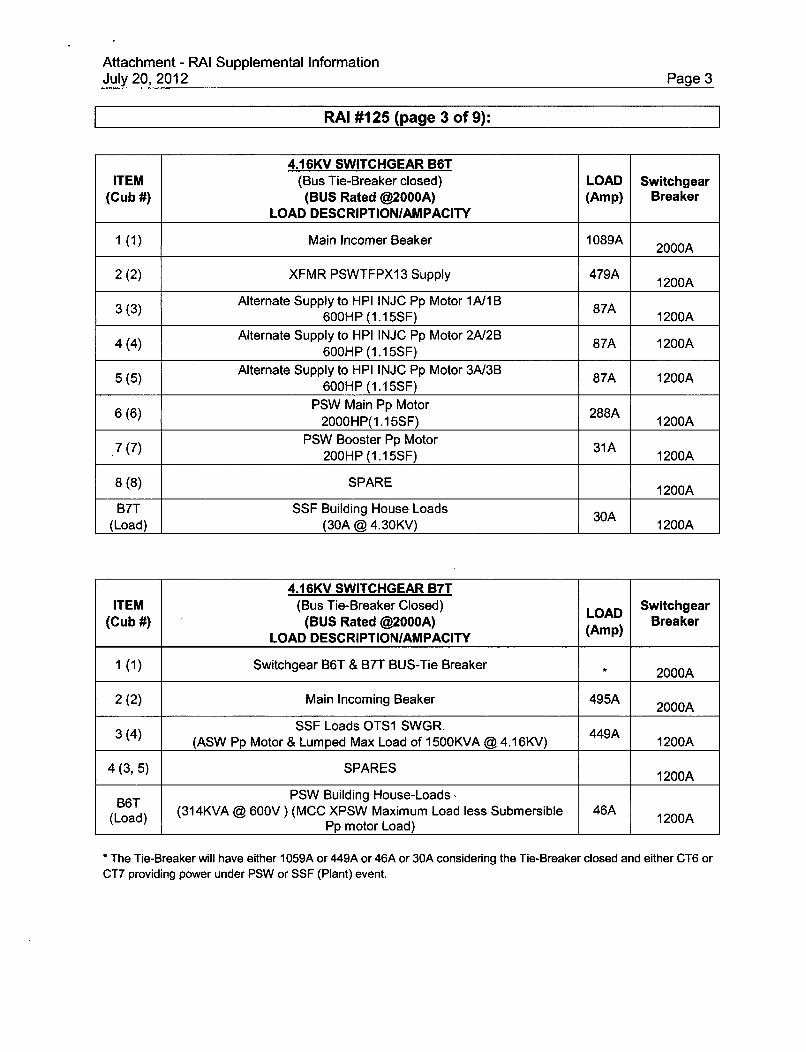
Attachment - RAI Supplemental InformationJuly 20, 2012 Page 3
RAI #125 (page 3 of 9):
4.16KV SWITCHGEAR B6TITEM (Bus Tie-Breaker closed) LOAD Switchgear
(Cub #) (BUS Rated @2000A) (Amp) BreakerLOAD DESCRIPTION/AMPACITY
1 (1) Main Incomer Beaker 1089A 2000A
2 (2) XFMR PSWTFPX13 Supply 479A 1200A
3(3) Alternate Supply to HPI INJC Pp Motor 1A/lB 87A600HP (1.15SF) A 1200A
4(4) Alternate Supply to HPI INJC Pp Motor 2A/2B 87A 1200A600HP (1.15SF)
5 (5) Alternate Supply to HPI INJC Pp Motor 3A/3B 87A 1200A600HP (1.15SF)
6 (6) PSW Main Pp Motor 288A2000HP(1.15SF) 1200A
7(7) PSW Booster Pp Motor 31A200HP (1.15SF) 1200A
8(8) SPARE 1200A
B7T SSF Building House Loads 30A(Load) (30A @ 4.30KV) 1200A
4.16KV SWITCHGEAR B7TITEM (Bus Tie-Breaker Closed) LOAD Switchgear
(Cub #) (BUS Rated @2000A) BreakerLOAD DESCRIPTION/AMPACITY (Amp)
1 (1) Switchgear B6T & B7T BUS-Tie Breaker 2000A
2 (2) Main Incoming Beaker 495A 2000A
3(4) SSF Loads OTS1 SWGR.(ASW Pp Motor & Lumped Max Load of 1500KVA @ 4.16KV) 449A 1200A
4(3,5) SPARES 1200A
36T PSW Building House-Loads
(Load) (314KVA @ 600V) (MCC XPSW Maximum Load less Submersible 46A 1200APp motor Load)
* The Tie-Breaker will have either 1059A or 449A or 46A or 30A considering the Tie-Breaker closed and either CT6 or
CT7 providing power under PSW or SSF (Plant) event.

Attachment - RAI Supplemental InformationJuly 20, 2012 Page 4
RAI #125 (page 4 of 9):
ITEM 600V LOAD CENTER PX13
(Cub #) BUS Rated 5000A LOAD Breaker SIZE
LOAD DESCRIPTION (Amp) (wlLSIG Units)
5000AF
1 5000A Sensor 'A' *
(5B) Load Center Main Incoming Supply Breaker 3318A *Derated to 88% (4400A)per Qualification Report
Section 5.2 800AF(1 B) Supply to PZR HTR MCC 3XJ 378A 600A Sensor 'F '
3 800AF(3D) Supply to PZR HTR MCC 3Xl 210A 600A Sensor A'
4 800AF(2A) Supply to PZR HTR MCC 3XK 168A 400A Sensor 'A'
5 800AF(2B) Supply to PZR HTR MCC 1XJ 322A 800A Sensor 'A'
6 800AF(20) Supply to PZR HTR MCC 2XJ 280A 600A Sensor 'A'
7 800AF(2D) Supply to PZR HTR MCC 2XK 168A 400A Sensor 'A'
8 800AF(3B) Supply to PZR HTR MCC lXK 126A 400A Sensor 'A'
9 1600AF(30) Supply to MCC 2XPSWA 362A 800A Sensor 'A'
10 8 600AF(3D) Supply to MCC 3XPSW 348A 800A Sensor 'A'
11 800AF(4B) Supply to PZR HTR MCC 2Xl 196A 600A Sensor 'A'
12 1600AF(40) Supply to MCC XPSW 414A 1200A Sensor 'A'
13 1600AF(40) Supply to MCC 1XPSW 346A 800A Sensor 'A'
14IA SPARE BREAKER OA 800AF w/800A Sensor 'A'(1A)15 15SPARE BREAKER OA
(1C) 800AF w/800A Sensor 'A'TOTAL LOAD (A) 3318A

Attachment - RAI Supplemental InformationJuly 20, 2012 Page 5
RAI #125 (page 5 of 9):
ITEM 600V MCC IXPSW LOAD(Cub #) BUS Rated @600A Breaker SIZE
LOAD DESCRIPTION (Ampacity)I MCC Main Incoming Supply 345.5A 600A TM
(1A) (MCC MAIN BUS RATED 600A)
2 4HP SizelSTM GEN 1A & 1B Flow ISO MOV 4.OA Starter W/(I1D) PSW6 20A TM
3 0.17HP SizelPSW STM 1A THROTTLE MOV 0.2A Starter W/(2B) 1PSW23 15A TM
4 0.17HP SizelPSW STM 1B THROTTLE MOV 0.2A Starter W/(2D) IPSW25 15A TM
2.6HP SizelRCP Seal Flow Outlet CNTL MOV 2.6A Starter W/
(3A) 1HP139 20ATM
6 0.17HP Size16 .7P0.2A Starter WI(3C) RCP Seal Flow CNTL MOV 1 HP140 ISA TM
Sizel7 2HP Starter W/
(3D) 1A HPI BWST Suction MOV 1HP24 15ATM
8 3.3HP Sizel83HP3.3A Starter WI(4A) HP INJC to Reactor Inlet MOV 1 HP26 20A TM
9 PSW ALT Feed to Existing Battery 159.OA 200A TM(4B) Charger ICA10 PSW ALT Feed to Existing Battery 159.OA 200A TM
(4C) Charger lCB11 Power PNL 1KPSW 15.OA 30ATM
(4D) 15KVA XMFR12
(3B, 5B, 5C, 5D & SPARE TM BREAKERS 20A, 30A, 200A, 20A &5E) 30A TM
13 SizelSPARE STARTERS Starter W/(2A, 2C, & 5A) 20A TM
TOTAL LOAD (A) 345.5A

Attachment - RAI Supplemental InformationJuly 20, 2012 Page 6
RAI #125 (page 6 of 9):
600V MCC 2XPSWAIBITEM LOADITEMLOADBreaker SIZE
(Cub #) BUS Rated 600A (Ampacity)LOAD DESCRIPTION/AMPACITY (A)
1 MCC Main Incoming Supply 361.2A 600A TM(1A) (MCC MAIN BUS RATED 600A)
Sizel2 4HP 4.OA Starter W/
(1 D) PSW STM GEN 2A & 2B Flow ISO MOV 2PSW6 20A TM
Size1l3 0.17HP 0.2A Starter W/
(2A) PSW STM 2B THROTTLE MOV 2PSW25 15A TMSize1
4 0.17HP 0.2A Starter W/(2B) PSW STM 2A THROTTLE MOV 2PSW23 15A TM
5 PSW Feed to Auto Transfer Switch for Control Battery 159.OA 200A TM(2D) Charger 2CA
6 POWER PANEL 2PSWPL2KPSW(3D) 15KVA XFMR
7 PSW PUMP ROOM EXH Fan 15.OA 50A TM(3E) 15HP
8 PSW Feed to Auto Transfer Switch for Control Battery 159.OA 200A TM(3F) Charger 2CB
Size19 0.66HP St rer
(4C) PSW RECIC MOV OPSW 14 0.7A Starter W/15A TM
Sizel10 2.6HP 2.6A Starter W/
(4D) RCP Seal Flow Injc Isolation CNTL MOV 2HP 139 20A TM
11 3.3HP Sizel
(5A) HP INJC to Reactor Inlet MOV 2HP26 3.3A Starter W/20A TM
12 0.17HP Size 1
(5B) RCP Seal Flow CNTL MOV 2HP 140 0.2A Starter W/15A TM
13 2HP Size 1
(5C) 2A HPI BWST Suction MOV 2HP 24 2.OA Starter W/15A TM
1414 SPARE TM BREAKERS OA 20A TM(3C)Sizel15 Starter WI
(2C, 4B, SPARE STARTERS OA 1at W/5D) 15, 20 &
20A TM
TOTAL LOAD (A) 361.2A

Attachment - RAI Supplemental InformationJuly 20, 2012 Page 7
RAI #125 (page 7 of 9):
600V MCC 3XPSWITEM LOADITEMLOADBreaker SIZE
(Cub #) BUS Rated 600A (Ampacity)LOAD DESCRIPTION
1 MCC Main Incoming Supply 347.5A 600A TM(1A) (MCC MAIN BUS RATED 600A)
2 PSW PUMP ROOM EXH Fan 0.OA) 15 HP 00anb 50A TM
(1 D) (Alternate Feed) Standby
Sizel3 4HP 4.OA Starter W/
(2A) PSW STM GEN 3A & 3B Flow ISO MOV 3PSW6 20A TM
4 0.17 HP Sizel
(2C) PSW STM 3A THROTTLE MOV 3PSW23 0.2A Starter W/1 5A TM
5 0.17HP Sizel
(3A) PSW STM 3B THROTTLE MOV 3PSW25 0.2A Starter W/_______1 5A TM
6 2.6HP Sizel626P2.6A Starter WI(3B) RCP Seal Flow INJC Isolation CNTL MOV 3HP 139 20A TM
7 0.17HP Sizel
(3C) RCP Seal Flow CNTL MOV 3HP 140 0.2A Starter W/15A TM
Sizel8 2HP 2.0A Starter W/
(3D) 3A HPI BWST Suction MOV 3HP 24 15ATM
Sizel9 3.3HP 3.3A Starter W/
(4A) HP INJC to Reactor Inlet MOV 3HP26 20ATM
10 PSW Feed to Auto Transfer Switch for Control Battery Charger 159.OA 200A TM(4B) 3CA
11 PSW Feed to Auto Transfer Switch for Control Battery Charger 159.OA 200A TM(4C) 3CB
12 0.66HP Sizel12 PSW REClC MOV OPSW 14 0.OA Starter W/
(5A) (Alternate Feed) 15A TM
13 Power Panel 3KPSW 15.OA 30A TM(5E) 15KVA XMR
14 2-1HP Emergency Cooling Priming Pp Motors 2.OA 20A TM(5D)
15(4D, 5B, SPARE TM BREAKERS OA 30A, 30A & 200A TM
5C0)
16 Sizel
(21,2D) SPARE STARTERS OA Starter W/20A TM
TOTAL LOAD (A) 347.5A

Attachment - RAI Supplemental InformationJuly 20, 2012 Page 8
RAI #125 (page 8 of 9):
Breaker SIZEITEM 600V MCC XPSW LOAD wICL(Cub BUS Rated 600A Ampacity (Current
#) LOAD DESCRIPTION Limiter)
1 MCC Main Incoming Supply 414A 600A TM(lC) MAIN BUS RATED 600A
2 PSW BLDG 208/120V Distribution PNL LP1 60A TM(2A) (45KVA XFMR) 45A W/CL
HVAC (Safety Related) Loads3 Heating &Ventilation Panel (PSWPLEC01) 100A 150A TM
(2C) (2-3HP(TR/EF), 2-10HP(BRJEF), 2-6KW(BR/HTR), 2- W/CL30KW(TR/HTR), 2KVA - CNTL/XMR)
HVAC (Safety Related) Loads4 Heating &Ventilation Panel ( PSWPLEC02) 0.0 150A TM
(3A) 2-3HP(TRJEF), 2-10HP(BR/EF), 2-6KW(BR/HTR), 2- Standby W/CL30KW(TR/HTR), 2KVA (CNTL/XMR)HVAC (Non-Safety Related) Loads
ISO XMR PSW TF203A/205A (600/480V) powering (2-Circuits5 Each Fused with 1OA Fuse) 6.5A 20A TM
(3B) 2-3HP AC Comp, 2-1/8HP Cooling Fans & 2-CNTL XMRs W/CL(480V/24V)
Isolation XMR)HVAC (Non-Safety Related) Loads
ISO XMR PSW TF204A/206A (600/480V) powering (2-Circuits6 Each Fused with 10A Fuse) 6.5A 20A TM
(3C) 2-3HP AC Comp, 2-1/8HP Cooling Fans & 2-CNTL XMRs W/CL(480V/24V)
Isolation XMR)7( PSW Battery Charger 1 82.OA 125A TM W/CL(3D)8 0.0A8 PSW Battery Charger 2 Sta 125A TM W/CL(4A) Standby
99 100HP Submersible Pp Motor (Size 4 Starter) 100A 150A TM W/CL(413)
HVAC (Non-Safety Related) Loads
(XMR Room Condenser PSWAH201&201A)10 2-Circuits for Compressors & Condensers Fused with 45A & 10A 37A 90A TM W/CL
(5A) Fuse respectively.2-15HP Compressors, 2-1HP Cooling Fans, 1-5HP 1-Condenser &
1-CNTL XMRHVAC (Non-Safety Related) Loads
(XMR Room Condenser PSWAH202&202A)11 2-Circuits for Compressors & Condensers Fused with 45A & 1 OA 37A 90A TM W/CL
(5B) Fuse respectively.2-15HP Compressors, 2-1HP Cooling Fans, 1-5HP 1-Condenser &
1-CNTL XMR12 50A,125A,
(2B, 125A, 70A4B, (SPARE TM BREAKERS) OA 125A ALL TM4C, BKR W/CL
5C,5D)TOTAL LOAD (A) 414A

Attachment - RAI Supplemental InformationJuly 20, 2012 Page 9
RAI #125 (page 9 of 9):
UNIT I 600V MCC IXK & IXJ (600A BUS)ITEM (PRESSURIZER HEATERS LOADS) LOAD
(Cub #) Ampacity(A)(LOAD DESCRIPTION)
MCC 1XK 126A126 KW Total Pressurizer Heaters Load
MCC IXJ 322A2 322 KW Pressurizer Load
UNIT 2 600V MCC 2XK, 2XJ & 2Xl (600A BUS)ITEM (PRESSURIZER HEATERS LOADS) LOAD
(Cub #) AmpacityLOAD DESCRIPTION/AMPACITY (A)
1 MCC 2XK 168A168 KW Total Pressurizer Heaters Load
MCC 2XJ 280A2 280KW Pressurizer Load
3 MCC 2XI 196A196 KW Total Pressurizer Heaters Load
UNIT 3 600V MCC 3XK, 3Xl & 3XJ (600A BUS)ITEM (PRESSURIZER HEATERS LOADS) LOAD
(Cub #) AmpacityLOAD DESCRIPTION/AMPACITY (A)
1 MCC 3XK 168A168 KW Total Pressurizer Heaters Load
MCC 3XJ 378A2 378 KW Pressurizer Load
MCC 3XI 210A3_ 210 KW Pressurizer Load

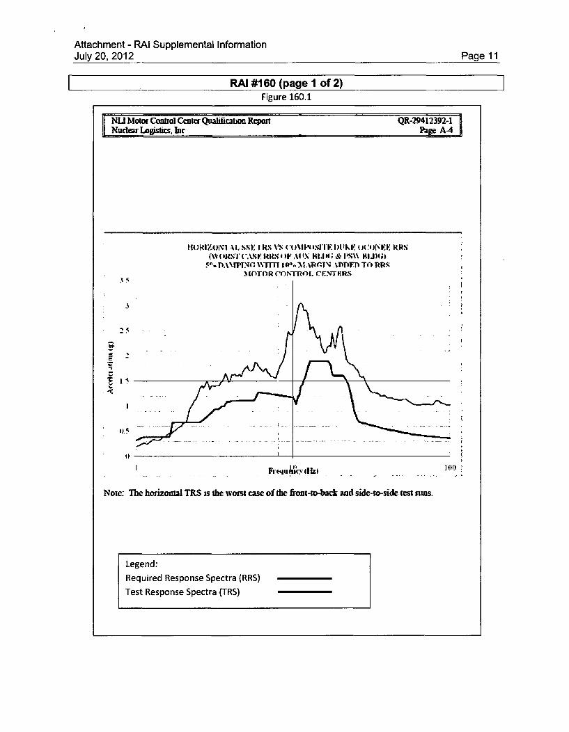
Attachment - RAI Supplemental InformationJuly 20, 2012 Page 11
RAI #160 (pagel1 of 2)Figure 160.1
NUL Motor Control Center Qualifican RepottNuChvr Logists. •c
QR-2412392-1%wge A-4
"oi-)IorviA I. sst1, tx '~ oVu (UPR'I ~'I ~)~~ .R(WORSTUNIA.Sr RRN 4W )A1 IXWN~ HI&, I'.%%% IL4J4~
5FO DANMUMN WMIT lO6,1MARi(.TNJAPP"r T41 RRS%ITO OTL :INtR
'3
E-
-, ~-.
Note: The horizontal TRS is the wonst case of the front-to-back and side-to-side test unws.
14Ic'
Legend:
Required Response Spectra (RRS)
Test Response Spectra (TRS)
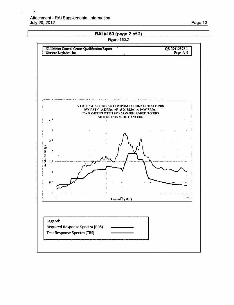
Attachment - RAI Supplemental InformationJuly 20, 2012 Page 12
RAI #160 (page 2 of 2)Figure 160.2
-lNU Mowa Contol Center Qualilication RtpoiNod=~ LO-Osics- brc
QR-29412392-1Page A-5
%IR11rA1. SSI. TRS VS ('O"[ONITY DUILF OCCONVE RRN(AVI hI45T CASE WINI IF .UX FILM) & M'W BLIn:)
*DW.flh If00aMARM~N ADDEDTORBSMYl OJR I'ONIRIL CLN'I ERS
C 6
I ~~F. t4juJ.Vn ilk) 11
Legend:
Required Response Spectra (RRS)
Test Response Spectra (TRS)