Embed Size (px)
Citation preview
5
Dumaclin
Dumaclin - DOC.0001 – EDITION 08 / 2014
The installation is similar for the 3 different types of exterior wall cladding T08 (185 cm) – T09 (170 cm) – T10 (150 cm)
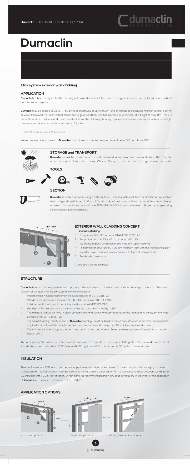
Click system exterior wall cladding APPLICATION Dumaclin has been designed for the covering of insulated and ventilated façades, on gables and sections of façades for newbuild
and renovation projects.
Dumaclin may be applied to Class I (°) buildings at an altitude of up to 1000m and on all façade structures whether concrete, stone
or wood framework, flat and vertical, stable and in good condition, whether insulated or otherwise, of a height of max. 8m - max. 2
floors (1)- and at a distance of 4m vis-à-vis the limits of the plot. (neighbouring façade). Dark shades – except for white/cream/light
grey – are not recommended on south-facing façades.
(°) Decree of 22.10.2010 and 19.07.2011
We recommend that you avoid a Dumaclin installation at an ambient temperature of below 0°C and above 30°C.
STORAGE and TRANSPORT Dumaclin should be stored in a dry, well ventilated area away from rain and direct UV rays, flat
or on a support inter-axis of max. 60 cm. Transport, handling and storage, always horizontal.
TOOLS
SECTION
Dumaclin is worked like wood using traditional tools. Hand saw with small teeth or circular saw with hollow
teeth of type sharp flat gap of 10 mm. LElectric tools will be connected to an appropriate vacuum cleaner
or failing this an anti-dust mask of type FFP2 (EN149 :2001) is recommended. Protect your eyes using
safety goggles during installation.
EXTERIOR WALL CLADDING CONCEPT1 Dumaclin cladding
2 Fixing screw 3.5 x 35 authentic STAINLESS STEEL A2
3 Support lathing min. 28 x 45 mm, spacing 40 cm(°).
We advise to put a ventilation profile onto the support lathing.
4 Primary rafter structure 50 x 80 mm minimum flush with the thermal insulation
5 Insulation layer, thickness in accordance with thermal requirements
6 Rain barrier membrane
(°) see structure advice below
STRUCTURE
Dumaclin boarding is always installed on a primary rafter structure that interlocks with the load bearing structure via fittings as a
function of the quality of the structure and of wind exposure.
• Implementation in accordance with the Specifications of CSTB 3316-V2
• Wood in accordance with standard NF EN 13183 and Class C18 – NF EN 338
• Individual sections chosen in accordance with standard NF EN 13183-2
• Wood given flame-retardant treatment with a max. degree of humidity of 18%
• The framework must be fixed in place using anchors and screws that are adapted to the load bearing structure and in ac-
cordance with CSTB 1661 – V2
• The support lathing – final support of Dumaclin boarding – must be fixed to the primary structure in the direction perpendic-
ular to the direction of the boards and fixed onto each intersection using two A2 stainless steel wood screws.
• The finished surface of support lathing must be flat with a gap of max. 2mm between adjacent rafters or 10 mm under a
ruler of 2m (°)
The inter-axes of the primary structure’s rafters are limited to max. 60 cm. The support lathing inter-axis is max. 40 cm in case of
light shades - the shades white (852)/ cream (840)/ Light grey (841) - and limited to 30 cm for all other shades.
INSULATION
Thermal Regulations 2012 are to be checked. Apply insulation in rigid panels classed in the «non-hydrophilic» category according to
DTU 20.1 and in fire classification M0 or polyurethane panels with fire classification M1, in accordance with specifications CSTB 3316-
V2. Insulator with ACERMI certification. A rain barrier is recommended and in any case compulsory in the event of the application
of Dumaclin on a wooden framework – see DTU 31.2.
APPLICATION OPTIONS
Horizontal application Vertical application Vertical/ diagonal application
No warranty if these instructions are not followed
EN
T08 T09 T10
6
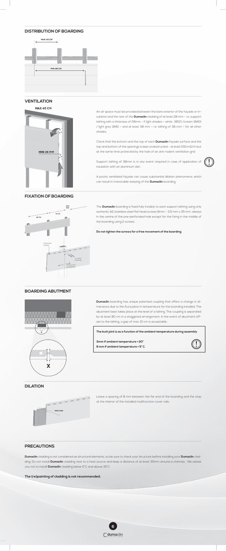
DISTRIBUTION OF BOARDING
VENTILATION
An air space must be provided between the bare exterior of the façade or in-
sulation and the rear of the Dumaclin cladding of at least 28 mm - i.e. support
lathing with a thickness of 28mm - if light shades – white (852) /cream (840)
/ light grey (841) – and at least 38 mm – i.e. lathing of 38 mm – for all other
shades.
Check that the bottom and the top of each Dumaclin façade surface and the
top and bottom of the openings is kept unobstructed - at least 100cm2/m but
at the same time protected by the hole of an anti-rodent ventilation grid.
Support lathing of 38mm is in any event required in case of application of
insulation with an aluminium skin.
A poorly ventilated façade can cause substantial dilation phenomena, which
can result in irrevocable warping of the Dumaclin boarding.
FIXATION OF BOARDING
The Dumaclin boarding is fixed fully invisibly to each support lathing using only
authentic A2 stainless steel flat head screws 8mm – 3.5 mm x 35 mm. always
in the centre of the pre-perforated hole except for the fixing in the middle of
the boarding using 2 screws.
Do not tighten the screws for a free movement of the boarding.
40 CM
40 CM
max100
trouspoinçonnées
milieu du clin
double visage
BOARDING ABUTMENT
Dumaclin boarding has unique patented coupling that offers a change in di-
mensions due to the fluctuation in temperature for the boarding installed. The
abutment best takes place at the level of a lathing. The coupling is separated
by at least 80 cm in a staggered arrangement. In the event of abutment off-
set to the lathing, a gap of max. 10 cm is acceptable.
The butt joint is as a function of the ambient temperature during assembly
3mm if ambient temperature = 20°
8 mm if ambient temperature = 5° C.
DILATION
Leave a spacing of 8 mm between the far end of the boarding and the stop
at the interior of the installed multifunction cover rails.
min 8 mm
PRECAUTIONS
Dumaclin cladding is not considered as structural elements, so be sure to check your structure before installing your Dumaclin clad-
ding. Do not install Dumaclin cladding next to a heat source and keep a distance of at least 30mm around a chimney. We advise
you not to install Dumaclin cladding below 0°C and above 30°C
The (re)painting of cladding is not recommended.
double screws
middle of boarding
middle of boarding
punched holes
7
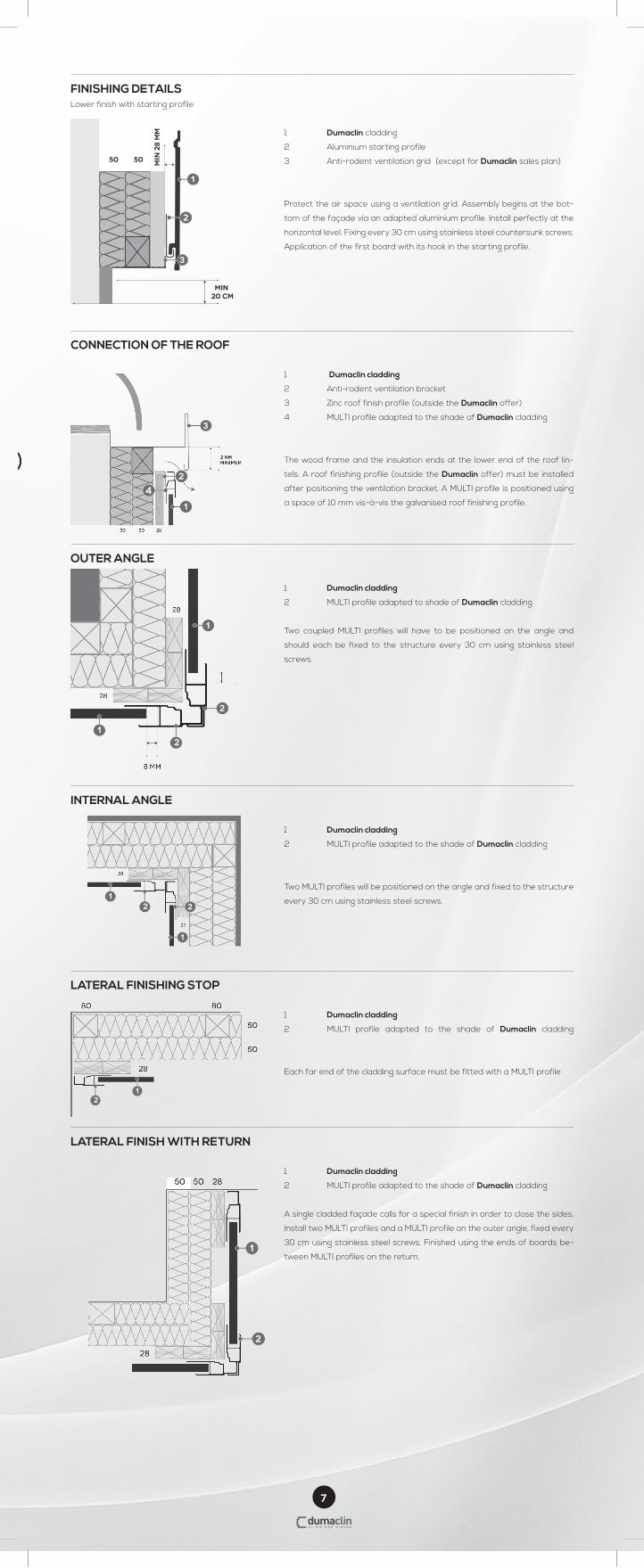
FINISHING DETAILSLower finish with starting profile
1 Dumaclin cladding
2 Aluminium starting profile
3 Anti-rodent ventilation grid (except for Dumaclin sales plan)
Protect the air space using a ventilation grid. Assembly begins at the bot-
tom of the façade via an adapted aluminium profile. Install perfectly at the
horizontal level. Fixing every 30 cm using stainless steel countersunk screws.
Application of the first board with its hook in the starting profile.
min
28
mm
min 20 cm
50 50
CONNECTION OF THE ROOF
1 Dumaclin cladding
2 Anti-rodent ventilation bracket
3 Zinc roof finish profile (outside the Dumaclin offer)
4 MULTI profile adapted to the shade of Dumaclin cladding
The wood frame and the insulation ends at the lower end of the roof lin-
tels. A roof finishing profile (outside the Dumaclin offer) must be installed
after positioning the ventilation bracket. A MULTI profile is positioned using
a space of 10 mm vis-à-vis the galvanised roof finishing profile.
OUTER ANGLE
1 Dumaclin cladding
2 MULTI profile adapted to shade of Dumaclin cladding
Two coupled MULTI profiles will have to be positioned on the angle and
should each be fixed to the structure every 30 cm using stainless steel
screws.
INTERNAL ANGLE
1 Dumaclin cladding
2 MULTI profile adapted to the shade of Dumaclin cladding
Two MULTI profiles will be positioned on the angle and fixed to the structure
every 30 cm using stainless steel screws.
LATERAL FINISHING STOP
1 Dumaclin cladding
2 MULTI profile adapted to the shade of Dumaclin cladding
Each far end of the cladding surface must be fitted with a MULTI profile
LATERAL FINISH WITH RETURN
1 Dumaclin cladding
2 MULTI profile adapted to the shade of Dumaclin cladding
A single cladded façade calls for a special finish in order to close the sides.
Install two MULTI profiles and a MULTI profile on the outer angle, fixed every
30 cm using stainless steel screws. Finished using the ends of boards be-
tween MULTI profiles on the return.
4
8
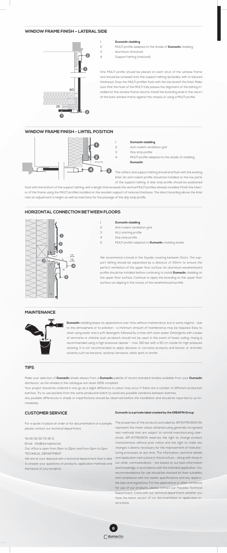
WINDOW FRAME FINISH – LATERAL SIDE
1 Dumaclin cladding
2 MULTI profile adapted to the shade of Dumaclin cladding
3 Aluminium threshold
4 Support lathing (reduced)
One MULTI profile should be placed on each strut of the window frame
and should be screwed onto the support lathing (probably with a reduced
thickness). Stop the MULTI profiles flush with the low levelof the lintel. Make
sure that the hook of the MULTI fully passes the alignment of the lathing in-
stalled on the window frame returns. Install the boarding ends in the return
of the bare window frame against the chassis or using a MULTI profile.
WINDOW FRAME FINISH – LINTEL POSITION
1 Dumaclin cladding
2 Anti-rodent ventilation grid
3 Drip strip profile
4 MULTI profile adapted to the shade of cladding
Dumaclin
The rafters and support lathing should end flush with the existing
lintel. An anti-rodent profile should be installed on the low parts
of the support lathing. A drip strip profile should be positioned
flush with the bottom of the support lathing, with a length that exceeds the vertical MULTI profiles already installed. Finish the interi-
or of the frame using the MULTI profiles installed on the wooden support of reduced thickness. The direct boarding above the lintel
risks an adjustment in height as well as insertions for the passage of the drip strip profile.
HORIZONTAL CONNECTION BETWEEN FLOORS
1 Dumaclin cladding
2 Anti-rodent ventilation grid
3 ALU starting profile
4 Drip strip profile
5 MULTI profile adapted to Dumaclin cladding shade
We recommend a break in the façade covering between floors. The sup-
port lathing should be separated by a distance of 20mm to ensure the
perfect ventilation of the upper floor surface. An aluminium weatherboard
profile should be installed before continuing to install Dumaclin cladding on
the upper floor surface. Continue to apply the boarding on the upper floor
surface via clipping in the recess of the weatherboard profile.
MAINTENANCE
Dumaclin cladding keeps its appearance over time without maintenance, but in some regions - due
to the atmosphere or to pollution - a minimum amount of maintenance may be required. Easy to
clean using water and a soft detergent, followed by a rinse with clean water. Detergents with a base
of ammonia or chlorine such as bleach should not be used. In the event of heavy soiling, rinsing is
recommended using a high-pressure cleaner – max. 100 bar with a 50 cm nozzle for high-pressure
cleaning. It is not recommended to apply abrasive or corrosive products and ketonic or aromatic
solvents such as benzene, acetone, kerosene, white spirit or similar.
TIPS
Make your selection of Dumaclin shade always from a Dumaclin palette of recent standard shades available from your Dumaclin
distributor, as the shades in the catalogue are never 100% compliant.
Your project should be ordered in one go as a slight difference in colour may occur if there are a number of different production
batches. Try to use packets from the same production batch to avoid any possible variations between batches.
Any possible differences in shade or imperfections should be observed before the installation and should be reported to us im-
mediately.
4
CUSTOMER SERVICE
For a quote, to place an order or for documentation or a sample,
please contact our technical department
Tel 00 32 50 72 90 11
Email: [email protected]
Our office is open from 9am to 12pm and from 2pm to 5pm
TECHNICAL DEPARTMENT
We are at your disposal with a technical department that is able
to answer your questions on products, application methods and
the layout of your projects.
Dumaclin is a private label created by the KREAFIN Group
The properties of the products extruded by API EXTRUSION SA
represent the mean values obtained using generally recognised
test methods that are subject to normal manufacturing toler-
ances. API EXTRUSION reserves the right to change product
characteristics without prior notice and the right to make any
changes it deems necessary for the improvement of manufac-
turing processes at any time. The information, technical details
and application instructions in this brochure - along with those in
our other communications - are based on our best information
and knowledge, in accordance with the intended application. Our
recommendations for use should be checked for their suitability
and compliance with the needs, specifications and any applica-
ble laws and regulations. For the applications or other conditions
for use of our products, please contact our Façades Technical
Department. Check with our technical department whether you
have the latest version of our documentation or application in-
structions.