Embed Size (px)
Citation preview

1
Duo Battery Charge Controller RENOGY 10A | 20A Pulse Width Modulation Solar Charge Controller Manual
2775 E. Philadelphia St., Ontario CA 91761 1-800-330-8678 Version: 1.2

2
Important Safety Instructions Please save these instructions. This manual contains important safety, installation, and operating instructions for the charge controller. The following symbols are used throughout the manual to indicate potentially dangerous conditions or important safety information.
WARNING: Indicates a potentially dangerous condition. Use extreme caution when performing this task. CAUTION: Indicates a critical procedure for safe and proper operation of the controller NOTE: Indicates a procedure or function that is important to the safe and proper operation of the controller. General Safety Information
Read all of the instructions and cautions in the manual before beginning the installation.
There are no serviceable parts for this controller. Do NOT disassemble or attempt to repair the controller.
Disconnect the solar module and fuse/breakers near to battery before installing or adjusting the PWM1020CC-DB.
Install external fuses/breakers as required.
Do NOT allow water to enter the controller.
Confirm that the power connections are tightened to avoid excessive heating from a loose connection.
Charge Controller Safety
NEVER connect the solar panel array to the controller without a battery. Battery must be connected first.
Ensure input voltage does not exceed 30 VDC (for 12V system) or 55VDC (for 24V system) to prevent permanent damage. Use the Open Circuit (Voc) to make sure the voltage does not exceed this value when connecting panels together.
Do not exceed 10A (PWM10DB) or 20A (PWM20DB). The Short Circuit (Isc) of the solar array should be less than 10A (PWM10DB) or 20A (PWM20DB).

3
Battery Safety
Use only sealed lead-acid, flooded, or gel batteries which must be deep cycle.
Explosive battery gases may be present while charging. Be certain there is enough ventilation to release the gases.
Be careful when working with large lead acid batteries. Wear eye protection and have fresh water available in case there is contact with the battery acid.
Carefully read battery manuals before operation.
Do NOT let the positive (+) and negative (-) terminals of the battery touch each other.
Recycle battery when it is replaced.
Over-charging and excessive gas precipitation may damage the battery plates and
activate material shedding on them. Too high of an equalizing charge or too long of one may cause damage. Please carefully review the specific requirements of the battery used in the system.
Equalization is carried out only for non-sealed / vented/ flooded / wet cell lead acid batteries.
Do NOT equalize sealed / VRLA type AGM / Gel cell batteries UNLESS permitted by battery manufacturer.
WARNING: Connect battery terminals to the charge controller BEFORE connecting the solar panel(s) to the charge controller. NEVER connect solar panels to charge controller until the battery is connected. WARNING: Do NOT connect any inverters or battery charger into the load terminal of the charge controller. WARNING: Once equalization is active in the battery charging, it will not exit this stage unless there is adequate charging current from the solar panel. There should be NO load on the batteries when in equalization charging stage.

4
Table of Contents General Information ...................................................................................................................................................5
Optional Components ...............................................................................................................................................6
Identification of Parts .................................................................................................................................................7
Installation ........................................................................................................................................................................8
Operation....................................................................................................................................................................... 13
Troubleshooting ......................................................................................................................................................... 15
Maintenance ................................................................................................................................................................ 15
Fusing.............................................................................................................................................................................. 15
Technical Specifications ....................................................................................................................................... 16
Dimensions .................................................................................................................................................................. 17

5
General Information The Renogy PWM1020CC-DB features dual battery charging capability making it great for RVs, caravans, and boats. With its advanced PWM charging technology, your batteries will be protected from discharging and over-charging. This controller is specifically designed for mobile off-grid applications supporting 12V deep cycle battery varieties such as sealed lead acid, gel, and flooded. The built-in RJ45 connector gives you the freedom of monitor the voltage, current and temperature of your system via MT-1 remote meter (sold separately). Key Features
12V / 24V auto recognition Micro controller digital accuracy High efficient PWM charging, increase the battery lifetime and improve the solar system
performance. Dual battery charging Sealed, Gel, and Flooded battery option. Remote temperature sensor (sold separated) Corrects the charging and discharging parameters automatically based on temperature
compensation, improving battery lifetime. Short circuit protection Battery reverse polarity protection Overcharging or discharging protection Overload protection
PWM Technology The PWM 10A/20ACC-Dual Battery utilizes Pulse Width Modulation (PWM) technology for battery charging. Battery charging is a current based process so controlling the current will control the battery voltage. For the most accurate return of capacity, and for the prevention of excessive gassing pressure, the battery is required to be controlled by specified voltage regulation set points for Absorption, Float, and Equalization charging stages. The charge controller uses automatic duty cycle conversion, creating pulses of current to charge the battery. The duty cycle is proportional to the difference between the sensed battery voltage and the specified voltage regulation set point. Once the battery reached the specified voltage range, pulse current charging mode allows the battery to react and allows for an acceptable rate of charge for the battery level.

6
Optional Components *The PWM10A/20A-Dual Battery charge controller is shipped by itself, without any additional components. Optional components that require a separate purchase:
Remote Temperature Sensor (TS-R): Measures the temperature
at the battery and uses this data for very accurate temperature
compensation. The sensor is supplied with a 6.6ft cable length that
connects to the charge controller. (Figure 1)
LCD Display Tracer Meter (MT-1): Allows for real time monitoring
of the charge controller. Perfect for circumstances where the user
cannot easily access the controller or modify its parameters. It is
supplied with a mounting frame and a cable that connects to the
RJ45 port on the Dual Battery Charge Controller. (Figure 2)
Figure 1
Figure 2

7
Identification of Parts
Key Parts
1. Local Temp. Sensor—Measures ambient temperature. Battery regulation is adjusted
accordingly. 2. Batt #1 status LED—Provides charging & battery status and errors 3. Batt #2 status LED—Provides charging & battery status and errors 4. Setting Indicator LEDs and Digital Display 5. SET Button 6. Remote Temp. Sensor (sold separately) — a connection point for RTS (optional) to remotely
monitor battery temperature. 7. Remote Meter Connection (RJ45) — a communication port for the remote meter MT-1 (sold
separately).
1 2
3
45
6 7
Figure 3
8
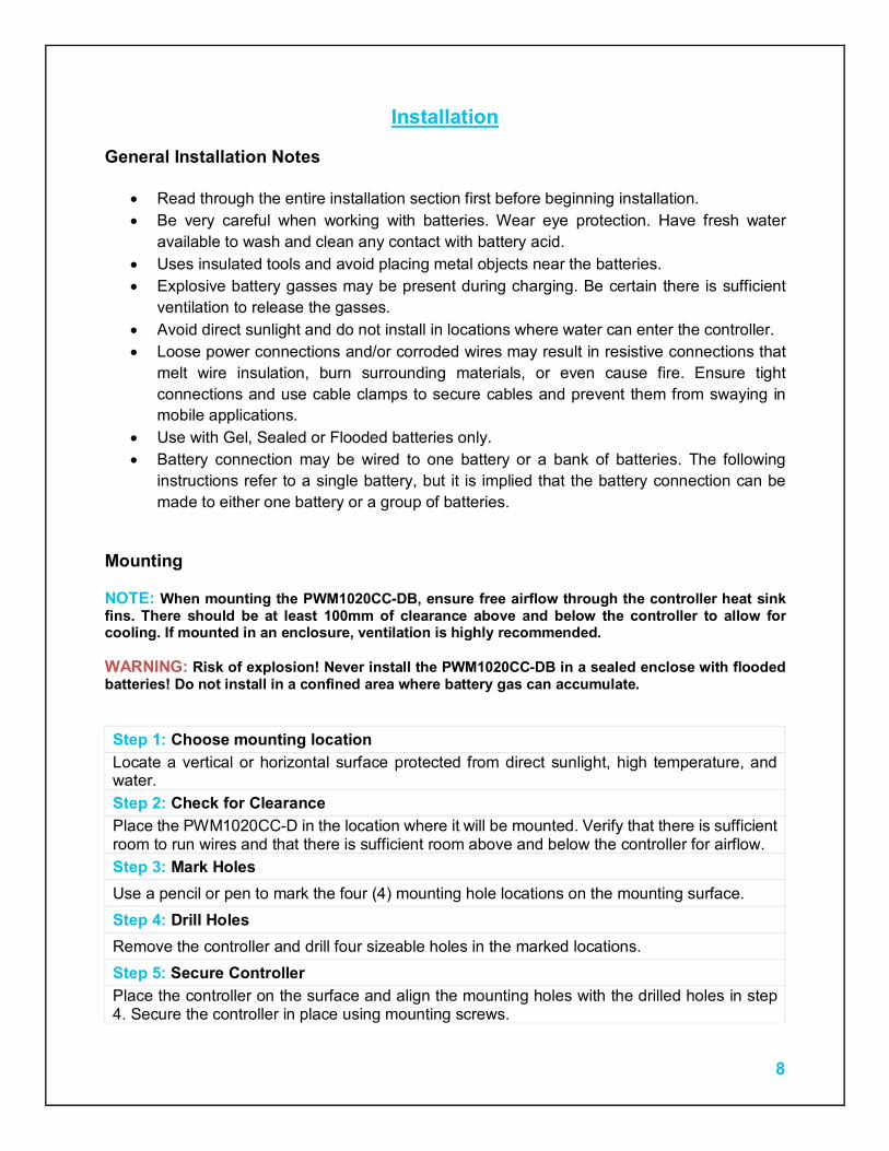
Installation General Installation Notes
Read through the entire installation section first before beginning installation. Be very careful when working with batteries. Wear eye protection. Have fresh water
available to wash and clean any contact with battery acid. Uses insulated tools and avoid placing metal objects near the batteries. Explosive battery gasses may be present during charging. Be certain there is sufficient
ventilation to release the gasses. Avoid direct sunlight and do not install in locations where water can enter the controller. Loose power connections and/or corroded wires may result in resistive connections that
melt wire insulation, burn surrounding materials, or even cause fire. Ensure tight connections and use cable clamps to secure cables and prevent them from swaying in mobile applications.
Use with Gel, Sealed or Flooded batteries only. Battery connection may be wired to one battery or a bank of batteries. The following
instructions refer to a single battery, but it is implied that the battery connection can be made to either one battery or a group of batteries.
Mounting NOTE: When mounting the PWM1020CC-DB, ensure free airflow through the controller heat sink fins. There should be at least 100mm of clearance above and below the controller to allow for cooling. If mounted in an enclosure, ventilation is highly recommended. WARNING: Risk of explosion! Never install the PWM1020CC-DB in a sealed enclose with flooded batteries! Do not install in a confined area where battery gas can accumulate. Step 1: Choose mounting location Locate a vertical or horizontal surface protected from direct sunlight, high temperature, and water. Step 2: Check for Clearance Place the PWM1020CC-D in the location where it will be mounted. Verify that there is sufficient room to run wires and that there is sufficient room above and below the controller for airflow. Step 3: Mark Holes Use a pencil or pen to mark the four (4) mounting hole locations on the mounting surface. Step 4: Drill Holes Remove the controller and drill four sizeable holes in the marked locations. Step 5: Secure Controller Place the controller on the surface and align the mounting holes with the drilled holes in step 4. Secure the controller in place using mounting screws.
9
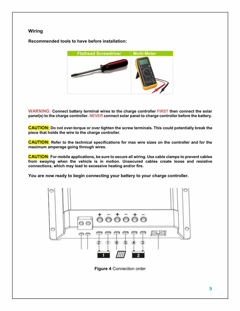
Wiring Recommended tools to have before installation:
Flathead Screwdriver Multi-Meter
WARNING: Connect battery terminal wires to the charge controller FIRST then connect the solar panel(s) to the charge controller. NEVER connect solar panel to charge controller before the battery. CAUTION: Do not over-torque or over tighten the screw terminals. This could potentially break the piece that holds the wire to the charge controller. CAUTION: Refer to the technical specifications for max wire sizes on the controller and for the maximum amperage going through wires. CAUTION: For mobile applications, be sure to secure all wiring. Use cable clamps to prevent cables from swaying when the vehicle is in motion. Unsecured cables create loose and resistive connections, which may lead to excessive heating and/or fire. You are now ready to begin connecting your battery to your charge controller.
Figure 4 Connection order
10
Battery
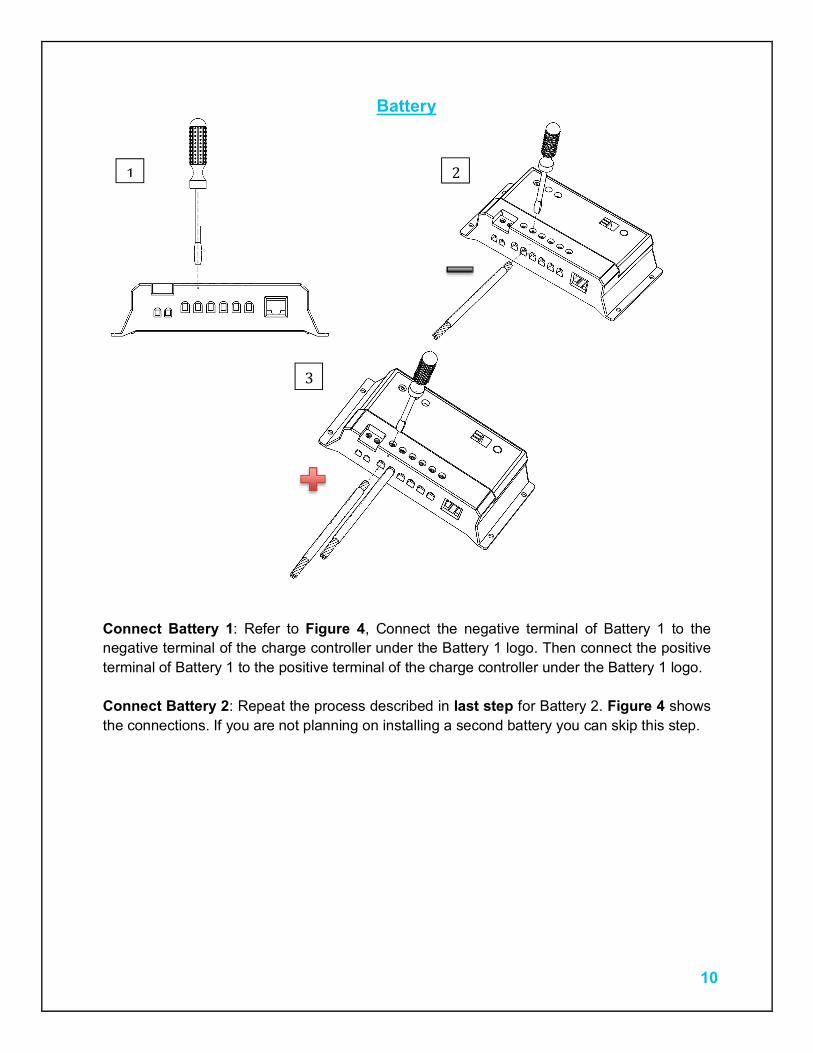
Connect Battery 1: Refer to Figure 4, Connect the negative terminal of Battery 1 to the negative terminal of the charge controller under the Battery 1 logo. Then connect the positive terminal of Battery 1 to the positive terminal of the charge controller under the Battery 1 logo. Connect Battery 2: Repeat the process described in last step for Battery 2. Figure 4 shows the connections. If you are not planning on installing a second battery you can skip this step.
1 2
3

11
Solar Panels
Connect the solar panel(s): Connect the negative PV lead of the solar panel to the negative terminal of the charge controller under the solar array logo. Then connect the positive lead of solar to the positive terminal of the charge controller under the solar array logo. Make sure the solar module(s) voltage and current do not exceed the ratings of the charge controller.
1 2
3
12
Temperature Sensor (if applicable)
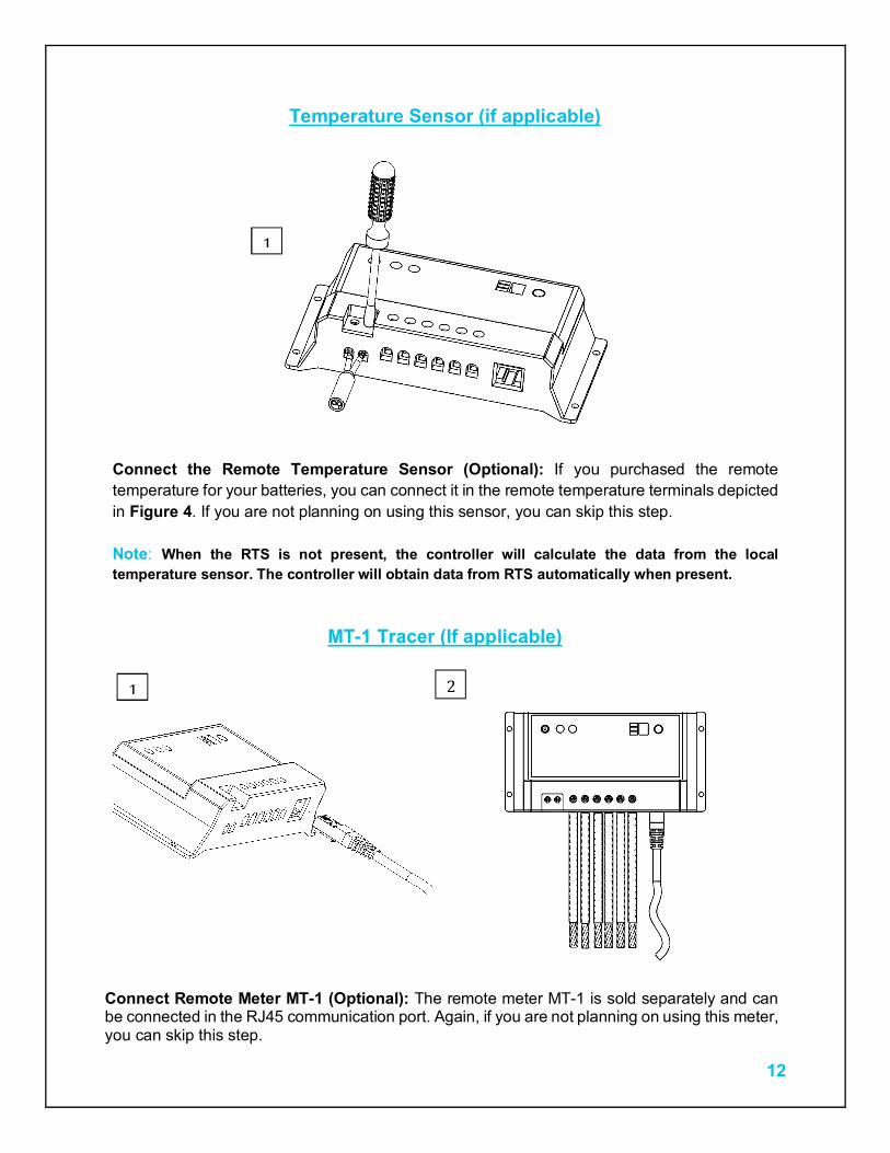
Connect the Remote Temperature Sensor (Optional): If you purchased the remote temperature for your batteries, you can connect it in the remote temperature terminals depicted in Figure 4. If you are not planning on using this sensor, you can skip this step. Note: When the RTS is not present, the controller will calculate the data from the local temperature sensor. The controller will obtain data from RTS automatically when present.
MT-1 Tracer (If applicable)
Connect Remote Meter MT-1 (Optional): The remote meter MT-1 is sold separately and can be connected in the RJ45 communication port. Again, if you are not planning on using this meter, you can skip this step.
1
1 2

13
Operation
Battery Type To select the battery type press the SET button on the controller a few times until the “Battery Type” LED lights up. Press the setting button again and hold it for 5 seconds until the digits start flashing. Press the setting button again to choose the battery type as described in Table 1. Leave it in this position, and it will stop flashing after a few seconds. The controller has recorded the battery setting.
Battery Type Digital Display
Sealed lead acid battery 1 Gel battery 2 Flooded battery 3
Table 1 Battery type setting Charging Priority To adjust the charging priority of the batteries press the setting button on the controller a few times until the “Charging priority” LED lights up. Press the setting button again and hold it for 5 seconds until the digits start flashing. Press the setting button again to choose the percentage level listed on Table 2. Leave it in this position, and it will stop flashing after a few seconds. The controller has recorded the Charging priority setting.
Number Battery #1 Battery #2
0 0% 100% 1 10% 90% 2 20% 80% 3 30% 70% 4 40% 60% 5 50% 50% 6 60% 40% 7 70% 30% 8 80% 20% 9 90% (pre-set) 10%
Table 2 Charging priority settings Note: In the normal charging conditions, the controller will distribute the charge for the selected setting. When Battery 1 is fully charged, charge will be diverted to Battery 2, and return to the no. 4 charging priority setting automatically when Battery 1 is low on voltage. When the controller detects that Battery 1 is the only battery connected, all the charge will go to the Battery 1 automatically. Charging frequency To change the charging frequency press the setting button on the controller a few times until the “Charging frequency” LED lights up. Press the setting button again and hold it for 5 seconds until the digits start flashing. Press the setting button again to choose a charging frequency listed on Table 3. Leave it in this position, and it will stop flashing after a few seconds. The controller has recorded the Charging priority setting.
14
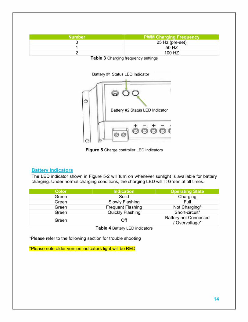
Number PWM Charging Frequency
0 25 Hz (pre-set) 1 50 HZ 2 100 HZ
Table 3 Charging frequency settings
Figure 5 Charge controller LED indicators Battery Indicators The LED indicator shown in Figure 5-2 will turn on whenever sunlight is available for battery charging. Under normal charging conditions, the charging LED will lit Green at all times.
Color Indication Operating State Green Solid Charging Green Slowly Flashing Full Green Frequent Flashing Not Charging* Green Quickly Flashing Short-circuit*
Green Off Battery not Connected / Overvoltage*
Table 4 Battery LED indicators *Please refer to the following section for trouble shooting *Please note older version indicators light will be RED
Battery #1 Status LED Indicator
Battery #2 Status LED Indicator

15
Troubleshooting
Check all connections to ensure they are secure and clean Check polarity of the battery connection and make sure the battery generates at least 6V Ensure the solar panels are exposed to sufficient light – ideally position them to face the
sun directly If charge controller states that there is short-circuit, please ensure that the panels are
connected correctly, and that the wires at the terminals are not touching each other. If one of the status LED is off and a battery is connected, check that the battery terminals
have good connection and that the polarity is correct. Check that the voltage doesn’t exceed the rated input voltage shown in Table 7-1 on Section 7.
If the charge controller is not charging, ensure that the panel’s polarity, and check for loose connections.
Maintenance For best controller performance, it is recommended that these tasks be performed from time to time.
1. Check that controller is mounted in a clean, dry, and ventilated area. 2. Check wiring going into the charge controller and make sure there is no wire damage or
wear. 3. Tighten all terminals and inspect any loose, broken, or burnt up connections 4. Make sure readings in the LEDs are consistent.
Fusing Fusing is a recommended in PV systems to provide a safety measure for connections going from panel to controller and controller to battery. Remember to always use the recommended wire gauge size based on the PV system and the controller.
NEC Maximum Current for different Copper Wire Sizes AWG 16 14 12 10 8 6 4 2 0 Max.
Current 10A 15A 20A 30A 55A 75A 95A 130A 170A
Table 5
16
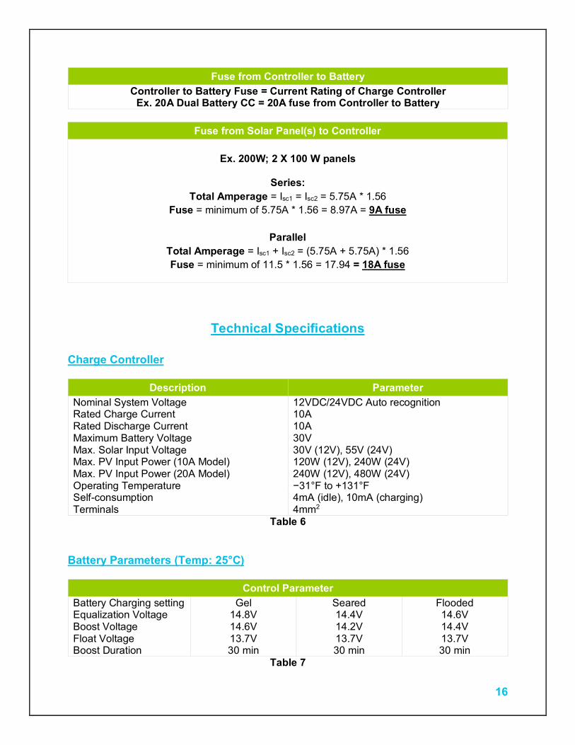
Fuse from Controller to Battery Controller to Battery Fuse = Current Rating of Charge Controller
Ex. 20A Dual Battery CC = 20A fuse from Controller to Battery
Technical Specifications Charge Controller
Description Parameter Nominal System Voltage 12VDC/24VDC Auto recognition Rated Charge Current 10A Rated Discharge Current 10A Maximum Battery Voltage 30V Max. Solar Input Voltage 30V (12V), 55V (24V) Max. PV Input Power (10A Model) 120W (12V), 240W (24V) Max. PV Input Power (20A Model) 240W (12V), 480W (24V) Operating Temperature −31°F to +131°F Self-consumption 4mA (idle), 10mA (charging) Terminals 4mm2
Table 6 Battery Parameters (Temp: 25°C)
Control Parameter Battery Charging setting Gel Seared Flooded Equalization Voltage 14.8V 14.4V 14.6V Boost Voltage 14.6V 14.2V 14.4V Float Voltage 13.7V 13.7V 13.7V Boost Duration 30 min 30 min 30 min
Table 7
Fuse from Solar Panel(s) to Controller
Ex. 200W; 2 X 100 W panels
Series: Total Amperage = Isc1 = Isc2 = 5.75A * 1.56
Fuse = minimum of 5.75A * 1.56 = 8.97A = 9A fuse
Parallel Total Amperage = Isc1 + Isc2 = (5.75A + 5.75A) * 1.56 Fuse = minimum of 11.5 * 1.56 = 17.94 = 18A fuse
17
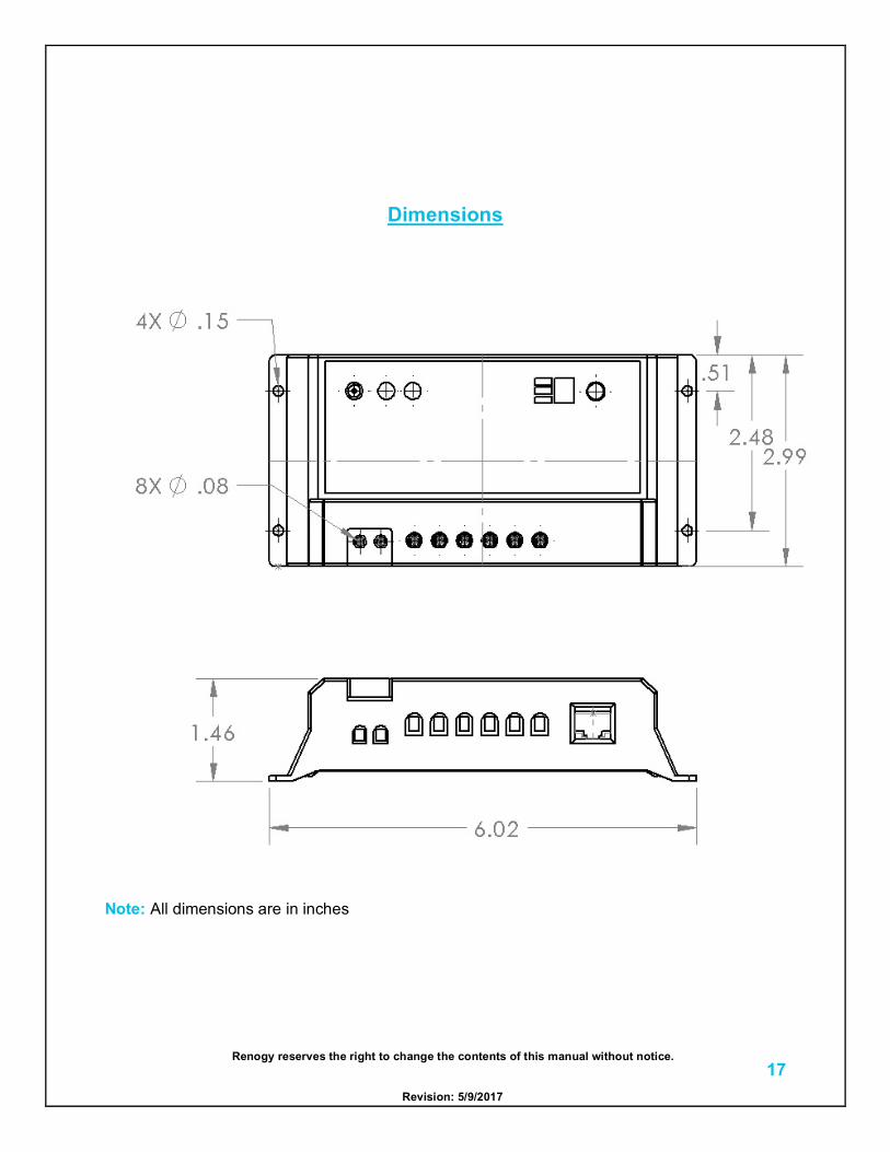
Dimensions
Note: All dimensions are in inches
Renogy reserves the right to change the contents of this manual without notice.
Revision: 5/9/2017