Embed Size (px)
Citation preview
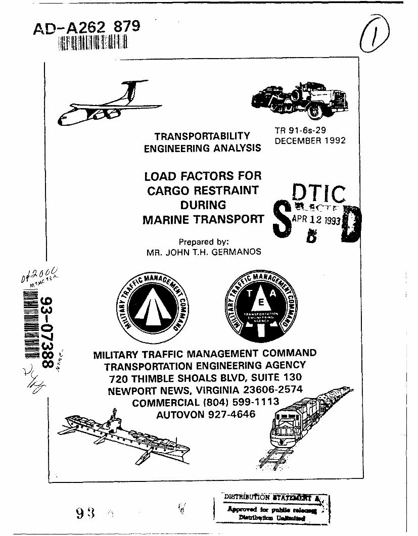
AD-A262 879
TRANSPORTABILITY TR 91-6s-29
ENGINEERING ANALYSIS DECEMBER 1992
LOAD FACTORS FORCARGO RESTRAINT DTIC
DURING SMARINE TRANSPORT OAPR12 1993'
Prepared by:MR. JOHN T.H. GERMANOS
7 SE
00O MILITARY TRAFFIC MANAGEMENT COMMAND
v) ~ TRANSPORTATION ENGINEERING AGENCY720 THIMBLE SHOALS BLVD, SUITE 130NEWPORT NEWS, VIRGINIA 23606-2574
COMMERCIAL (804) 599-1113AUTOVON 927-4646
9f r
CONTENTS
PAU
1. EXECUTIVE SUMMARY ............................................................. 1
II. BA CK G RO U N D ......................................................................... I
III. ANALYSIS ............................................................................. 3
A. Acceleration Equations .......................................................... 3
B. Load Factor Equations .......................................................... 6
C. Assumptions and Rationale ................................................... 6
D. Findings ............................................................................. 8
IV. CONCLUSION .......................................................................... 10
V. RECOMMENDATIONS .............................................................. 12
APPENDIXES
A. MSC Memorandum on Eftects of G-Forces During Marine Transport .... A-i
B. Load Factor Example Calculation ............................................... B-I
GLOSSARY
DISTRIBUTION
Accession For
St #A, Auth MTMC/TEA ,"(Ms. Napiecek - DSN 927-4646) -•
Telecon, 12 Apr 93 - CBByDI 5 tx ,buton/iAvpilability Codeli
jAvel. end/orDIst 40 3 ai-I ' I
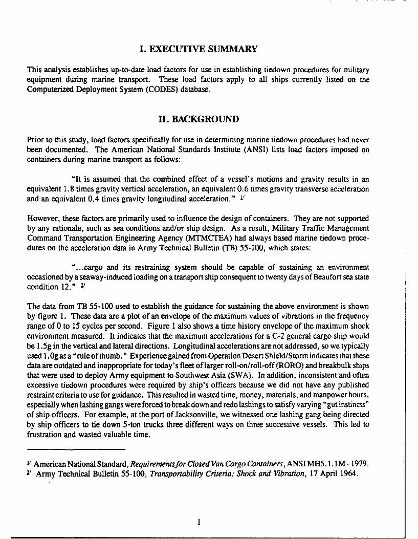
I. EXECUTIVE SUMMARY
This analysis establishes up-to-date load factors for use in establishing tiedown procedures for militaryequipment during marine transport. These load factors apply to all ships currently listed on theComputerized Deployment System (CODES) database.
II. BACKGROUND
Prior to this study, load factors specifically for use in determining marine tiedown procedures had neverbeen documented. The American National Standards Institute (ANSI) lists load factors imposed oncontainers during marine transport as follows:
"It is assumed that the combined effect of a vessel's motions and gravity results in anequivalent 1.8 times gravity vertical acceleration, an equivalent 0.6 times gravity transverse accelerationand an equivalent 0.4 times gravity longitudinal acceleration." 1-
However, these factors are primarily used to influence the design of containers. They are not supportedby any rationale, such as sea conditions and/or ship design. As a result, Military Traffic ManagementCommand Transportation Engineering Agency (MTMCTEA) had always based marine tiedown proce-dures on the acceleration data in Army Technical Bulletin (TB) 55-100, which states:
"...cargo and its restraining system should be capable of sustaining an environmentoccasioned by a seaway-induced loading on a transport ship consequent to twenty days of Beaufort sea statecondition 12." 2'
The data from TB 55-100 used to establish the guidance for sustaining the above environment is shownby figure 1. These data are a plot of an envelope of the maximum values of vibrations in the frequencyrange of 0 to 15 cycles per second. Figure 1 also shows a time history envelope of the maximum shockenvironment measured. It indicates that the maximum accelerations for a C-2 general cargo ship wouldbe 1.5g in the vertical and lateral directions. Longitudinal accelerations are not addressed, so we typicallyused 1.0g as a "rule of thumb." Experience gained from Operation Desert Shield/Storm indicates that thesedata are outdated and inappropriate for today's fleet of larger roll-on/roll-off (RORO) and breakbulk shipsthat were used to deploy Army equipment to Southwest Asia (SWA). In addition, inconsistent and oftenexcessive tiedown procedures were required by ship's officers because we did not have any publishedrestraint criteria to use for guidance. This resulted in wasted time, money, materials, and manpower hours,especially when lashing gangs were forced to break down and redo lashings to satisfy varying "gut instincts"of ship officers. For example, at the port of Jacksonville, we witnessed one lashing gang being directedby ship officers to tie down 5-ton trucks three different ways on three successive vessels. This led tofrustration and wasted valuable time.
-1 American National Standard, Requirementsfor Closed Van Cargo Containers, ANSI MH5. 1. I M - 1979.2' Army Technical Bulletin 55-100, Transportability Criteria: Shock and Vibration, 17 April 1964.
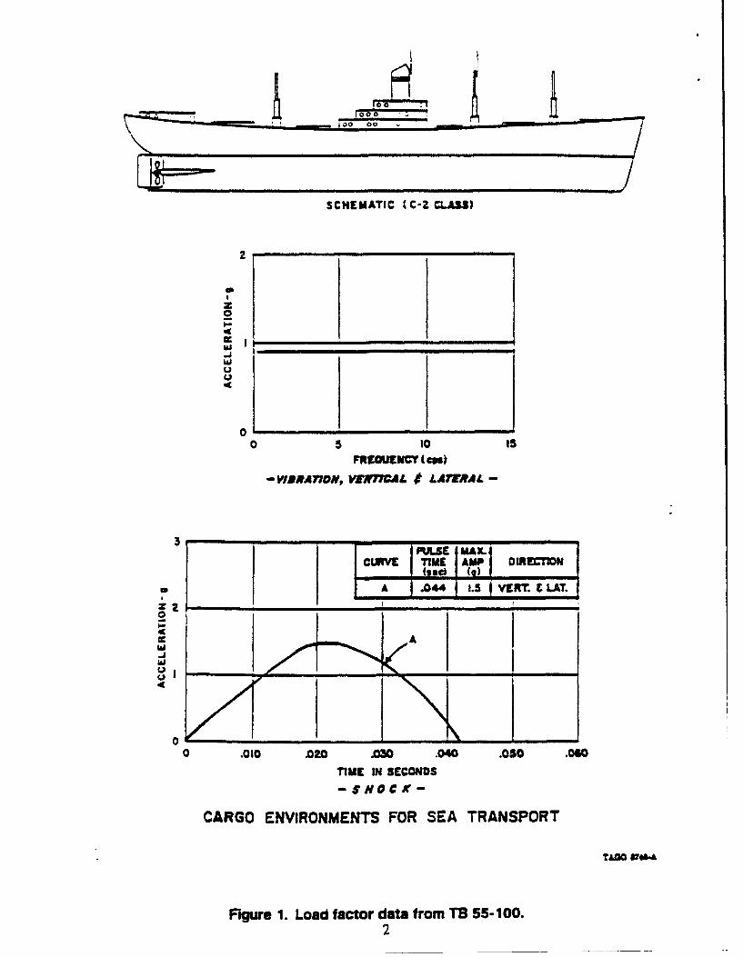
SCHEMATIC C-Z CLASS)
2
CC Iw
04
0 5 10 15FRC0UENCY (C")
-WBR, A7AoN, VERnTCAL "M LATRAL -
3p -
'PU9S MAXCUM TIME AMP DIRECTION(,,c, (3)-:A .044 1.5 VERT.
....... T,,
01
4/4
0 .010 .020 =0 .040 .050 .060
TIME IN SECONDS-S$OCK-
CARGO ENVIRONMENTS FOR SEA TRANSPORT
TAoM W".A
Figure 1. Load factor data from TB 55-100.2
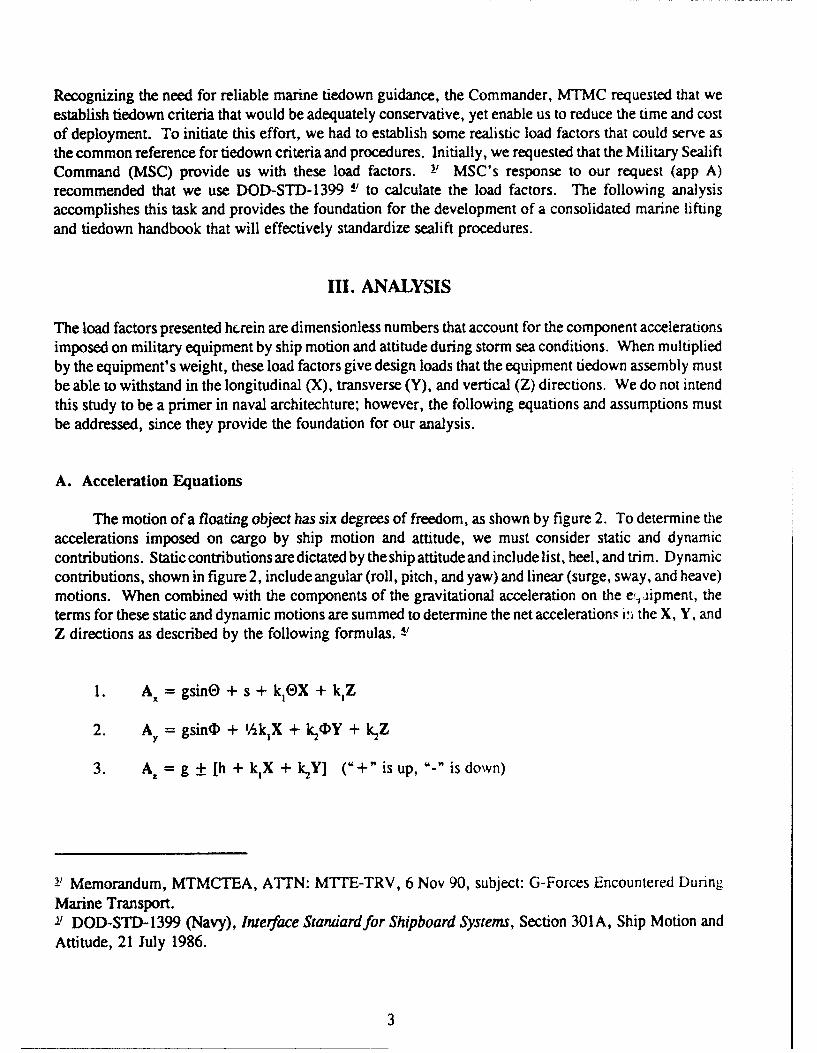
Recognizing the need for reliable marine tiedown guidance, the Commander, MTMC requested that weestablish tiedown criteria that would be adequately conservative, yet enable us to reduce the time and costof deployment. To initiate this effort, we had to establish some realistic load factors that could serve asthe common reference for tiedown criteria and procedures. Initially, we requested that the Military SealiftCommand (MSC) provide us with these load factors. 1, MSC's response to our request (app A)recommended that we use DOD-STD-1399 1' to calculate the load factors. The following analysisaccomplishes this task and provides the foundation for the development of a consolidated marine liftingand tiedown handbook that will effectively standardize sealift procedures.
III. ANALYSIS
The load factors presented herein are dimensionless numbers that account for the component accelerationsimposed on military equipment by ship motion and attitude during storm sea conditions. When multipliedby the equipment's weight, these load factors give design loads that the equipment tiedown assembly mustbe able to withstand in the longitudinal (X), transverse (Y), and vertical (Z) directions. We do not intendthis study to be a primer in naval architechture; however, the following equations and assumptions mustbe addressed, since they provide the foundation for our analysis.
A. Acceleration Equations
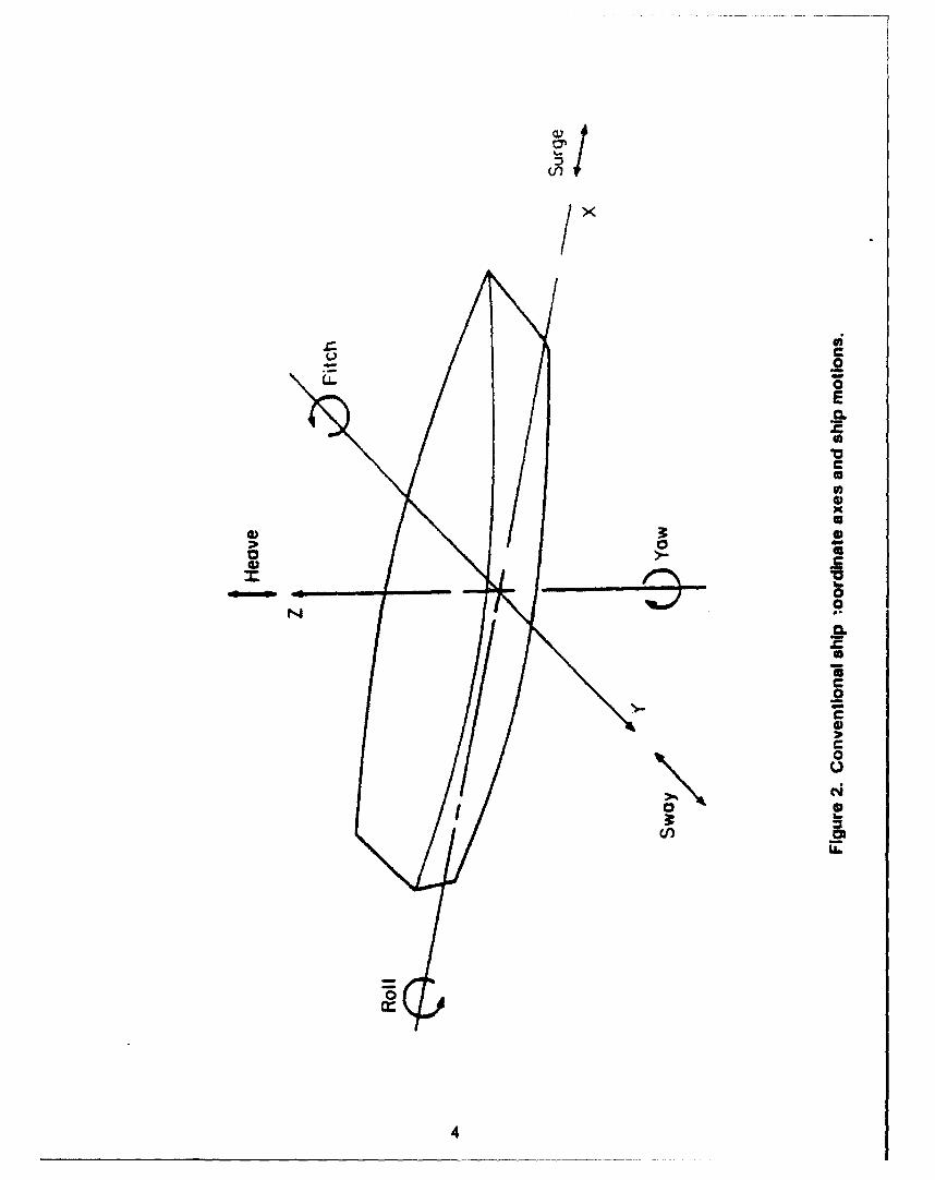
The motion of a floating object has six degrees of freedom, as shown by figure 2. To determine theaccelerations imposed on cargo by ship motion and attitude, we must consider static and dynamiccontributions. Static contributions are dictated by the ship attitude and include list, heel, and trim. Dynamiccontributions, shown in figure 2, include angular (roll, pitch, and yaw) and linear (surge, sway, and heave)motions. When combined with the components of the gravitational acceleration on the ejipment, theterms for these static and dynamic motions are summed to determine the net accelerations 1% the X, Y, andZ directions as described by the following formulas. -1
1. AX = gsinO + s + kOX + k,Z
2. Ay = gsincI + 'AkX + k2cY + k2 Z
3. A. = g ± [h + k,X + k2Y] ("+" is up, "- is down)
3_ Memorandum, MTMCTEA, ATTN: MTTE-TRV, 6 Nov 90, subject: G-Forces Encountered DunrngMarine Transport.-1 DOD-STD-1399 (Navy), Interface Standard for Shipboard Systems, Section 301 A, Ship Motion andAttitude, 21 July 1986.
3
(ill
WiU C
- .2
E
0
CU00U
4) 3 0C
C S0) C
aU.
.9.0*1C.2C0C
0N NS3 h.
'/)
4
Where,
4. k, = 4t'E)/T,2 (T = (C'B)/CIM
and,
5. k, = 4n24)/T 2
The variables and symbols used in the above equations are defined as follows:
A = component acceleration in the longitudinal directionAY = component acceleration in the transverse direction
Az = component acceleration in the vertical direction
0 = maximum pitch angle (rad)
(I = maximum roll angle (rad)
s = surge acceleration (m/s2 or ft/s2)
h = heave acceleration (m/s2 or ft/s2)
g = acceleration caused by gravity (mis 2 or ftls 2)
TP = pitch period (sec)
Tr = roll period (sec)
GM = maximum metacentric height (m or ft)
B = maximum beam at or below the waterline (m or ft)
C = roll constant (sW/JI
X = longitudinal distance from CG (m or ft)
Y = transverse distance from CG (m or ft)
Z = vertical distance above CG (m or ft)
N X, Y, and Z define the stowage location farthest from the ship's center of gravity (CG).
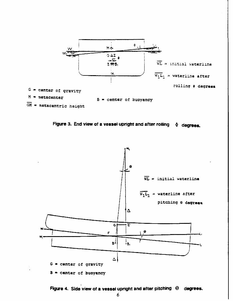
Many of the above symbols and/or terms appear in the Glossary. In addition, figurcs 3 and 4 illustratethe two most significant dynamic motions (rolling and pitching) along with some appropriate symbols.
5
W M 46-
5 iqsWL = ..t.al aterlilne
W-, L waterline after
G - center of gravity rling degrees
M -metacanter B - cenzer of buoyancy
GM metacentric height
Figure 3. End view of a vessel upright and after roiling i degres.
e
WL =initial waterline
W-•I waterline after
pitching 8 degrees
G - center of gravity
B - center of buoyancy
Figure 4. Side view of a vessel upright and after pitching e degrees.6
B. Load Factor Equations
Once the component accelerations have been calculated as shown above, determination of the loadfactors is relatively simple. The following equations define these load factors.
1. L 2, = A.g longitudinal load factor
2. L• = A/g transverse load factor
3. Lf, = A./g vertical load factor
C. Assumptions and Rationale
To conduct our analysis for a "worst case" scenario, we made the following assumptions. Rationaleis included where appropriate.
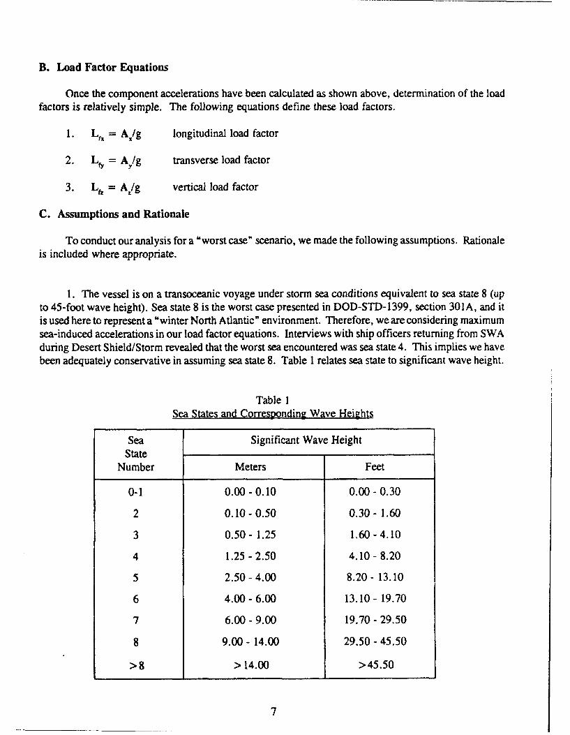
1. The vessel is on a transoceanic voyage under storm sea conditions equivalent to sea state 8 (upto 45-foot wave height). Sea state 8 is the worst case presented in DOD-STD-1399, section 301 A, and itis used here to represent a "winter North Atlantic" environment. Therefore, we are considering maximumsea-induced accelerations in our load factor equations. Interviews with ship officers returning from SWAduring Desert Shield/Storm revealed that the worst sea encountered was sea state 4. This implies we havebeen adequately conservative in assuming sea state 8. Table 1 relates sea state to significant wave height.
Table ISea States and Corresponding Wave Heights
Sea Significant Wave HeightState
Number Meters Feet
0-1 0.00-0.10 0.00-0.30
2 0.10-0.50 0.30-1.60
3 0.50- 1.25 1.60-4.10
4 1.25-2.50 4.10- 8.20
5 2.50-4.00 8.20- 13.10
6 4.00-6.00 13.10 - 19.70
7 6.00 - 9.00 19.70 - 29.50
8 9.00 - 14.00 29.50 - 45.50
> 8 > 14.00 > 45.50
7
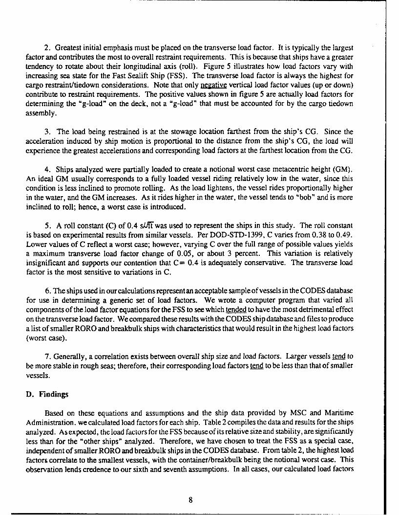
2. Greatest initial emphasis must be placed on the transverse load factor. It is typically the largestfactor and contributes the most to overall restraint requirements. This is because that ships have a greatertendency to rotate about their longitudinal axis (roll). Figure 5 illustrates how load factors vary withincreasing sea state for the Fast Sealift Ship (FSS). The transverse load factor is always the highest forcargo restraint/tiedown considerations. Note that only negative vertical load factor values (up or down)contribute to restraint requirements. The positive values shown in figure 5 are actually load factors fordetermining the "g-load" on the deck, not a "g-load" that must be accounted for by the cargo tiedownassembly.
3. The load being restrained is at the stowage location farthest from the ship's CG. Since theacceleration induced by ship motion is proportional to the distance from the ship's CG, the load willexperience the greatest accelerations and corresponding load factors at the farthest location from the CG.
4. Ships analyzed were partially loaded to create a notional worst case metacentric height (GM).An ideal GM usually corresponds to a fully loaded vessel riding relatively low in the water, since thiscondition is less inclined to promote rolling. As the load lightens, the vessel rides proportionally higherin the water, and the GM increases. As it rides higher in the water, the vessel tends to "bob" and is moreinclined to roll; hence, a worst case is introduced.
5. A roll constant (C) of 0.4 s/rt was used to represent the ships in this study. The roll constantis based on experimental results from similar vessels. Per DOD-STD-1399, C varies from 0.38 to 0.49.Lower values of C reflect a worst case; however, varying C over the full range of possible values yieldsa maximum transverse load factor change of 0.05, or about 3 percent. This variation is relativelyinsignificant and supports our contention that C= 0.4 is adequately conservative. The transverse loadfactor is the most sensitive to variations in C.
6. The ships used in our calculations represent an acceptable sample of vessels in the CODES databasefor use in determining a generic set of load factors. We wrote a computer program that varied allcomponents of the load factor equations for the FSS to see which tended to have the most detrimental effecton the transverse load factor. We compared these results with the CODES ship database and files to producea list of smaller RORO and breakbulk ships with characteristics that would result in the highest load factors(worst case).
7. Generally, a correlation exists between overall ship size and load factors. Larger vessels tend tobe more stable in rough seas; therefore, their corresponding load factors tend to be less than that of smallervessels.
D. Findings
Based on these equations and assumptions and the ship data provided by MSC and MaritimeAdministration. we calculated load factors for each ship. Table 2 compiles the data and results for the shipsanalyzed. As expected, the load factors for the FSS because of its relative size and stability, are significantlyless than for the "other ships" analyzed. Therefore, we have chosen to treat the FSS as a special case,independent of smaller RORO and breakbulk ships in the CODES database. From table 2, the highest loadfactors correlate to the smallest vessels, with the container/breakbulk being the notional worst case. Thisobservation lends credence to our sixth and seventh assumptions. In all cases, our calculated load factors
8
-j <
<UULLJ
U-)
0 U) 0
ou-
U-4
-Sj
I
9
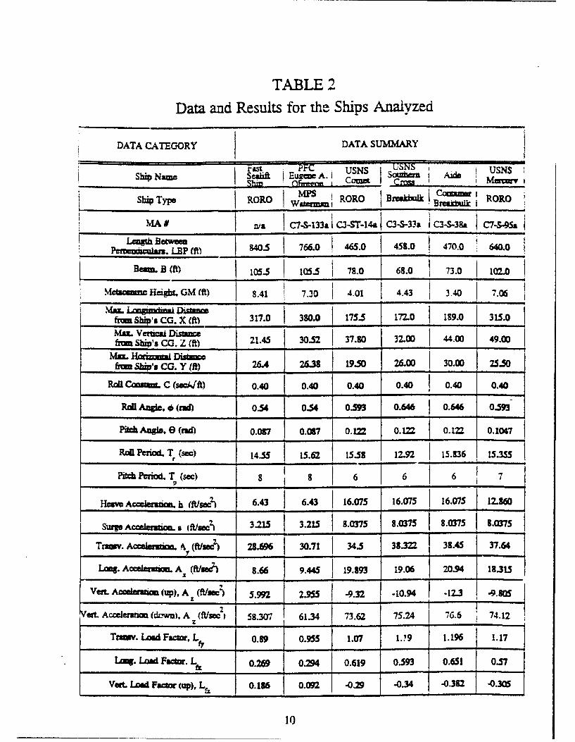
TABLE 2
Data and Results for the Ships Analyzed
DATA CATEGORY DATA SUMMARY
Shp~r ISani EuAI USNS USNS USNSSbi_ Nam SAii_ EU_ A. i Comet Sm s I MUS i
Ship Type _WbCm= ROO_
MA w C7S-33aC3ST-4aC3-S-33a C3-S-38a 04..S&9n/ iI C• .a45.
Legt Bww0 Q 766.0 465.0 480 470.0 60.P a ...... ... LB (f )
B. (f) 105-5 10i5. 78.0 68.0 73.0 1(Y2.0Pe ca1z LE1t __....___ __ _ _ ___ __
Metammm: Height, GM (ft) 8.41 7.30 4.01 4.43 3.40 7.06
from Ship's CG. X (ft) 317.0 380.0 177.5 177-0 189.0 315.0
Max. Vertical Distane3(5 32n I4f I490fro Shiis CG. Z (ft) 21.40 37.80 37-00 00 49.00
Mmx Harhma Distae I ~-frm S",s cm. Y fft) 26.4 2638 19.50 26.00 30.00 25.50
Roa Cam= C (secf A) 0.40 0.40 0.40 0.40 0.40 0.40
RaU Angie , (rad)0.54 0.54 0.593 0.646 0.646 0.59-
Pich Angle, 0 (thd) 0.07 0.0•7 OM 0.12 I 0. 0.1047
Rail Period. T f(see) 14.557 15.62t 153 12.92.. 15.936 ISMS5
Pitch Peiod. T (sc) 8 6 6 6 7
Have Accemdon. h (ft/sec) 6.43 6.43 16.075 16.075 16.075 12.1%60
Supg Accelenm & flc. t/weJ 3.215 3215. L .07 8 .0375 805 9(7
Trn=v. Ack,,,mu. y (ftfuJ 28.M 30.71 34.5 38.322 38.45 37.64
Ltmg. AcMI*lan. A (xf w/e) 8.66 9.445 I 19.893 19.06 20.94 13.315
Vert. Accelau~m (up), A (ft(1c) 599.9 __ _-IZ _ 2.3oet. Accelemlcm (do-•), A M/3=21 58.307 61.34 73.62 75.24 76.6 74.12
Traimv. Load Factor, LfL 0.89 0.955 1.07 1.'9 1.196 1.17
L9. LUnd Faor. Lfz 0.269 o.4 0.619 0.593 0.651 0.57
Vet. Load Facr (up), Lf 0.136 0.092 -0.29 -0.34 -0.312 -0.30S
10
were significantly less than those historically used by MTMC for planning marine restraintL/tiedownprocedures. Table 3 compares our results with the load factors previously used and shows the percentreduction resulting from our study. Appendix B contains an example calculation for the vessel, Aide, sinceit presented the worst case load factors. Similar calculations were done for each vessel analyzed by usingthe equations in paragraphs III A and B. Our calculations and results were sent to MSC for approval inFebruary 1991. 11 MSC concurred with our results, stating that "These factors are considered conservativeand satisfactory for ship cargo loadings." t"
These load factors provide the common base required for developing general tiedown proceduresfor marine transport. Once developed, these procedures will be incorporated into MTMCTEA Pamphlet55-22, Marine TerminalLifting and Tiedown Guidance. We published similar pamphlets for rail tiedown(MTMCTEA Pam 55-19) and marine lifting (MTMCTEA Pam 56-1). These pamphlets were usedextensively during Desert Shield/Storm operations. MTMCTEA Pam 55-22 will consolidate the revisionof MTMCTEA Pam 56-1 (lifting manual) with the newly developed tiedown guidance, to produce acomprehensive marine terminal reference that military and commercial shippers did not have in the past.The net result will be more efficient loading operations at the ports.
IV. CONCLUSION
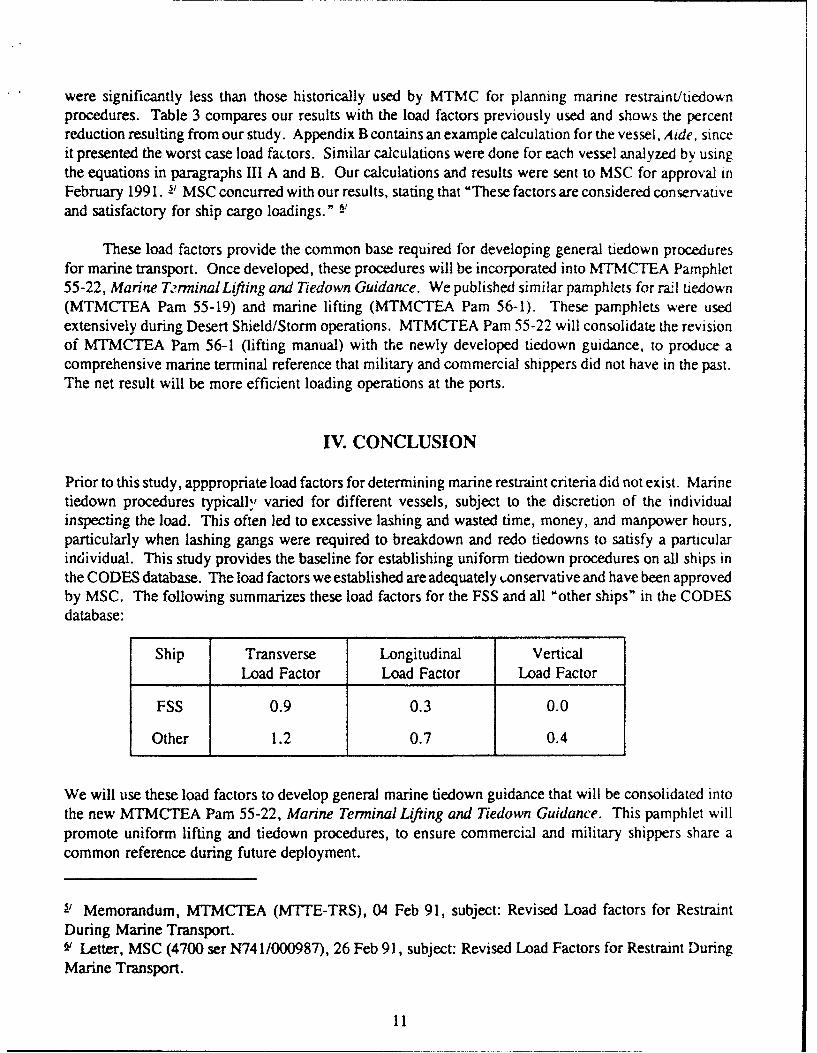
Prior to this study, apppropriate load factors for determining marine restraint criteria did not exist. Marinetiedown procedures typically varied for different vessels, subject to the discretion of the individualinspecting the load. This often led to excessive lashing and wasted time, money, and manpower hours,particularly when lashing gangs were required to breakdown and redo tiedowns to satisfy a particularindividual. This study provides the baseline for establishing uniform tiedown procedures on all ships inthe CODES database. The load factors we established are adequately -.onservative and have been approvedby MSC. The following summarizes these load factors for the FSS and all "other ships" in the CODESdatabase:
Ship Transverse Longitudinal Vertical
Load Factor Load Factor Load Factor
FSS 0.9 0.3 0.0
Other 1.2 0.7 0.4
We will use these load factors to develop general marine tiedown guidance that will be consolidated intothe new MTMCTEA Pam 55-22, Marine Terminal Lifting and Tiedown Guidance. This pamphlet willpromote uniform lifting and tiedown procedures, to ensure commercial and military shippers share acommon reference during future deployment.
s_ Memorandum, MTMCTEA (M'ITE-TRS), 04 Feb 91, subject: Revised Load factors for RestraintDuring Marine Transport.V- Letter, MSC (4700 ser N741/000987), 26 Feb 91, subject: Revised Load Factors for Restraint DuringMarine Transport.
11
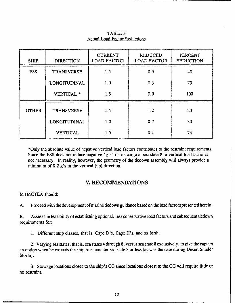
TABLE 3Actual Load Factor Reduction3
CURRENT REDUCED PERCENT
SHIP DIRECTION LOAD FACTOR LOAD FACTOR REDUCTION
FSS TRANSVERSE 1.5 0.9 40
LONGITUDINAL 1.0 0.3 70
VERTICAL * 1.5 0.0 100
OTHER TRANSVERSE 1.5 1.2 20
LONGITUDINAL 1.0 0.7 30
VERTICAL 1.5 0.4 73
*Only the absolute value of negative vertical load factors contributes to the restraint requirements.
Since the FSS does not induce negative "g's" on its cargo at sea state 8, a vertical load factor isnot necessary. in reality, however, the geometry of the tiedown assembly will always provide aminimum of 0.2 g's in the vertical (up) direction.
V. RECOMMENDATIONS
MTMCTEA should:
A. Proceed with the development of marine tiedown guidance based on the load factors presented herein.
B. Assess the feasibility of establishing optional, less conservative load factors and subsequent tiedownrequirements for:
1. Different ship classes, that is, Cape D's, Cape H's, and so forth.
2. Varying sea states, that is, sea states 4 through 8, versus sea state 8 exclusively, to give the captainan optionr when he expects the ship to encounter sea state 8 or less (as was the case during Desert Shield/Storm).
,3. Stowage locations closer to the ship's CG since locations closest to the CG will require little orno restraint.
12
C. Coordinate all future related progress and findings extensively throughout DOD and the commercialshipping industry.
Note: For ships not in the CODES database, ships with unusual ship loading configurations, and/or ship'swith extraordinary dimensions, load factors should be calculated on a case-by-case basis to ensure theyare less than or equal to those presented in this analysis. MTMCTEA will be happy to assist and/or performthese calculations on a request basis.
In addition, questions and/or suggestions pertaining to this study should be addressed to:
Director, MTMCTEAATTN: MTTE-TRV (Mr. John Germanos)720 Thimble Shoals Blvd - Suite 130Newport News, VA 23606-2574
13
APPENDIX A
MSC Memorandum on Effects of G-Forces During Marine Transport
A-1
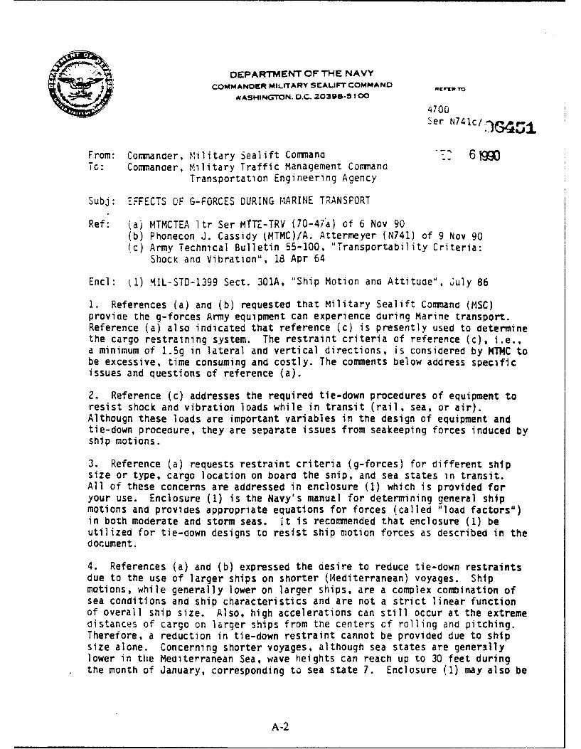
DEPARTMENT OF THE NAVY
COMMANDER MILITARY SEALIFT COMMAND mrto
WASHINGTON. D.C. 20396-5 100
'4700Ser N74lc/
From: Commander, Military Sealift Coniano -_- 6M9To: Comiancer, Military Traffic Management Commanc
Transportation Engineering Agency
Subj: EFFECTS OF G-FORCES DURING MARINE TRANSPORT
Ref: (a) MTMCTEA Itr Ser MTTE-TRV (70-47a) of 6 Nov 90(b) Phonecon J. Cassidy (MTMC)/A. Attermeyer (N741) of 9 Nov 90(c) Army Technical Bulletin 55-100, "Transportability Criteria:
ShocK and Vibration", 18 Apr 64
Encl: £1) MIL-STD-1399 Sect. 301A, "Ship Motion and Attitude", July 86
I. References (a) and (b) requested that Military Sealift Commana (MSC)provide the g-forces Army equipment can experience during Marine transport.Reference (a) also indicated that reference (c) is presently used to determinethe cargo restraining system. The restraint criteria of reference (c), i.e.,a minimum of 1.5g in lateral and vertical directions, is considered by MTMC tobe excessive, time consuming and costly. The comments below address specificissues and questions of reference (a).
2. Reference (c) addresses the required tie-down procedures of equipment toresist shock and vibration loads while in transit (rail, sea, or air).Althougn these loads are important variables in the design of equipment andtie-down procedure, they are separate issues from seakeeping forces induced byship motions.
3. Reference (a) requests restraint criteria (g-forces) for different shipsize or type, cargo location on board the snip, and sea states in transit.All of these concerns are addressed in enclosure (1) which is provided foryour use. Enclosure (1) is the Navy's manual for determining general shipmotions and provides appropriate equations for forces (called "load factors")in both moderate and storm seas. it is recommended that enclosure (1) beutilized for tie-down designs to resist ship motion forces as described in thedocument.
4. References (a) and (b) expressed the desire to reduce tie-down restraintsdue to the use of larger ships on shorter (Mediterranean) voyages. Shipmotions, while generally lower on larger ships, are a complex combination ofsea conditions and ship characteristics and are not a strict linear functionof overall ship size. Also, high accelerations can still occur at the extremedistances of cargo on larger ships from the centers of rolling and pitching.Therefore, a reduction in tie-down restraint cannot be provided due to shipsize alone. Concerning shorter voyages, although sea states are generfllylower in the Mediterranean Sea, wave heights can reach up to 30 feet duringthe month of January, corresponding to sea state 7. Enclosure (1) may also be
A-2
Subj: EFFECTS OF G-FORCES DURING MARINE TRANSPORT
utilized to determine appropriate loading forces in the Mediterranean on acase-by-case basis. However, any voyage originating on the East Coast (U.S.)but transiting through the Mediterranean should have cargo restraint for anocean voyage.
AY D-recz3o
A-3
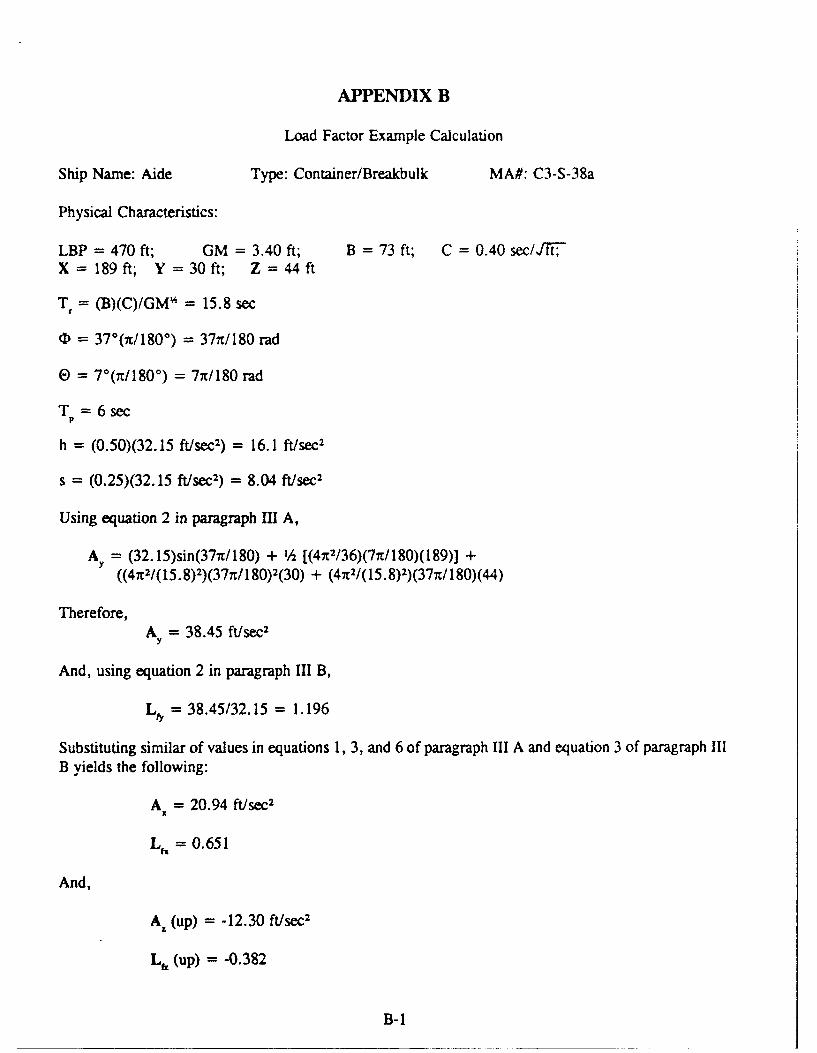
APPENDIX B
Load Factor Example Calculation
Ship Name: Aide Type: Container/Breakbulk MA#: C3-S-38a
Physical Characteristics:
LBP = 470 ft; GM = 3.40 ft; B =73 ft; C =0.40 sec/JTF,X = 189ft; Y = 30ft; Z =44ft
T = (B)(C)/GM' = 15.8 sec
S= 37"(n/180*) = 37nt/180 rad
0 = 7° r/180°) = 7nr/180 rad
T =6sec
h (0.50)(32.15 ft/sec2) = 16.1 ft/sec 2
s = (0.25)(32.15 ft/sec2) = 8.04 ft/sec2
Using equation 2 in paragraph Ill A,
AY = (32.15)sin(37nr/180) + 1/h [(47t2/36)(7rt/180)(189)] +((4n2/(15.8)2)(377t/ 180)2(30) + (4n 2/(15.8)2)(37n/ 180)(44)
Therefore,A = 38.45 ft/sec2
y
And, using equation 2 in paragraph III B,
LfY = 38.45/32.15 = 1.196
Substituting similar of values in equations 1, 3, and 6 of paragraph III A and equation 3 of paragraph IIIB yields the following:
A = 20.94 ft/sec2
X
Lf, = 0.651
And,
Az (up) = -12.30 ft/sec2
L,. (up) = -0.382
B-I
GLOSSARY
1. Angular motions - the oscillatory motions of roll, pitch, and yaw.
2. Attitude, ship's - defined by a ship's list, trim, and heel; the net inclination of a ship in the water.
3. Beam - the extreme width of a ship at or below the waterline.
4. Design load - the force applied to cargo at a given location in the ship, determined by multiplying thecargo mass by the load factor(s). This is the load the tiedown assembly must be capable of restraining.
5. "g-load" or "g-force" - acceleration caused by gravity (9.807 m/sec2 or 32.15 ft/sec2 ).
6. Heave - the up and down motion of a ship along the vertical (Z) axis.
7. Heel - the nonoscillating angular displacement of a ship about the longitudinal (X) axis caused by steadyexternally imposed loads (that is wind, control surface, and so forth).
8. Length between perpendiculars - the length of a ship measured from the forward perpendicular to theafter perpendicular.
9. Linear motions - motions contributed by heave, surge and sway along the respective axes.
10. List, also called "heel"- the inclination of a ship about the longitudinal (X) axis caused by either lateralseparation between the center of gravity and the center of buoyancy or by steady externally imposed
loads (that is wind or control surface).
11. Load factor - a calculated number in terms of gravitational and dynamic acceleration, which, whenmultiplied by the mass of cargo, determines the design load that the cargo tiedown assembly mustrestrain in the longitudinal, transverse, and vertical directions as a result of the accelerations of gravityand ship motions.
12. Metacentric height - distance from the ship's center of gravity to the metacenter; a measure of the
vessel's stability in the upright or nearly upright condition.
13. Pitch - the oscillatory motion of a ship about the transverse (Y) axis.
14. Roll - the oscillatory motion of a ship about the longitudinal (X) axis.
15. Sea state - a measure of the severity of the sea conditions, to include wave height, period, energydistribution with wave frequency, and direction.
16. Ship's motion - the motions defined by the six degrees of freedom of a floating vessel (roll, pitch, yaw,surge, sway, and heave).
17. Surge - fore and aft motion of a ship along the longitudinal (X)axis.
18. Sway - the lateral motion of a ship along the transverse (Y) axis.
19. Tiedown assembly - all components of the restraint system that must secure the cargo to the designload requirements dictated by the respective load factors; includes cargo tiedown provisions, chains,load binders, shackles, deck tiedowns, and so forth.
20. Trim - the inclination of a ship about the transverse (Y) axis caused by longitudinal separation of thecenter of gravity and the center of buoyancy.
21. Yaw - the oscillatory motion of a ship about the vertical (Y) axis.
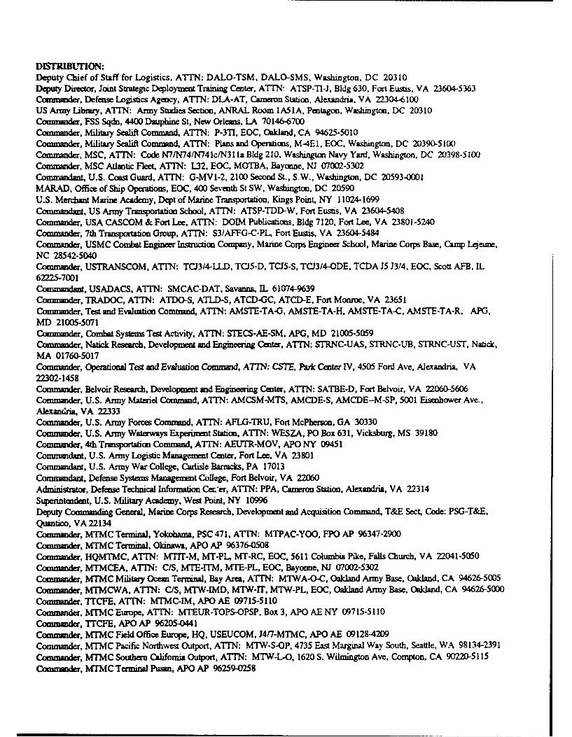
DISTRIBUrION:Deputy Chief of Staff for Logistics, ATTN: DALO-TSM, DALO-SMS, Washington, DC 20310Deputy Director, Joint Strategic Deployment Training Center, ATTIN: ATSP-TI-i, Bldg 630, Fort Eusis, VA 23604-5363Cortmnader, Defense Logistics Agency, ATTN: DLA-AT, Cameron Station, Alexandria, VA 22304-6100US Army Library, ATTN: Army Studies Section, ANRAL Room IA51A, Pentagon, Washington, DC 20310Commander, FSS Sqdn, 4400 Dauphine St, New Orleans, LA 70146-6700Czmmander, Military Sealift Command, ATTN: P-3TI, EOC, Oakland, CA 94625-5010Commander, Military Sealif" Command, AITN: Plans and Operations, M4E 1, EOC, Washington, DC 20390-5100Commander, MSC, ATTN: Code N7/N74/N741c/N3 la Bldg 210, Washington Navy Yard, Washington, DC 20398-5100Commander, MSC Atlantic Fleet, ATTN: L32, EOC, MOTBA, Bayonne, NJ 07002-5302Commandant, U.S. Coast Guard, ATTN: G-MVI-2, 2100 Second St., S.W., Washington, DC 20593-0001MARAD, Office of Ship Operations, EOC, 400 Seventh St SW, Washington, DC 20590U.S. Merchant Marine Academy, Dept of Marine Transportation, Kings Point, NY 11024-1699Commandant, US Army Transportation School, ATTN: ATSP-TDD-W, Fort Eustis, VA 23604-5408Commander, USA CASCOM & Fort Lee, ATTN: DOIM Publications, Bldg 7120, Fort Lee, VA 23801-5240Commander, 7th Transportation Group, ATTN: S3/AFFG-C-PL, Fort Eustis, VA 23604-5484Commander, USMC Combat Engineer Instruction Company, Marine Corps Engineer School, Marine Corps Base, Camp Lejeun,NC 28542-5040Commander, USTRANSCOM, ATTN: TCJ3/4-LLD, TCJ5-D, TCJS-S, TCJ3/4-ODE, TCDA J5 J3/4, EOC, Scott AFB, IL62225-7001Commandant, USADACS, AMTN: SMCAC-DAT, Savanna, IL 61074-9639Commander, TRADOC, ATTN: ATDO-S, ATLD-S, ATCD-GC, ATCD-E, Fort Monroe, VA 23651Commander, Test and Evaluation Command, ATTN: AMSTE-TA-G, AMSTE-TA-H, AMSTE-TA-C, AMSTE-TA-R, APG,MD 21005-5071Commander, Combat Systems Tea Activity, ATTN: STECS-AE-SM, APO, MD 21005-5059Commander, Natick Research, Development and Engineering Center, ATTN: STRNC-UAS, STRNC-UB, STRNC-UST, Natick,MA 01760-5017Commander, Operational Test and Evaluation Command, ATTN: CS'7, Park Center IV, 4505 Ford Ave, Alexandria, VA22302-1458Commander, Belvoir Research, Developmnt and Engineering Center, ATTN: SATBE-D, Fort Belvoir, VA 22060-5606Commander, U.S. Army Materiel Command, ATTN: AMCSM-MTS, AMCDE-S, AMCDE-M-SP, 5001 Eisenhower Ave.,Alexandria, VA 22333Commander, U.S. Army Forces Command, ATTN: AFLG-TRU, Fort McPherson, GA 30330Commander, U.S. Army Waterways Experiment Station, ATTN: WESZA, PO Box 631, Vicksburg, MS 39180Commander, 4th Transportation Command, ATrN: AEUTR-MOV, APO NY 09451Commandant, U.S. Army Logistic Management Center, Fort Lee, VA 23801Commandant, U.S. Army War College, Carlisle Barracks, PA 17013Commmadant, Defense Systems Managemet College, Fort Belvoir, VA 22060Administrator, Defense Technical Information Cecer, ATTN: PPA, Cameron Station, Alexandria, VA 22314Superintendent, U.S. Military Academy, West Point, NY 10996Deputy Commanding General, Marine Corps Research, Development and Acquisiion Command, T&E Sect, Code: PSG-T&E,Quantico, VA 22134Commander, MTMC Terminal, Yokohama, PSC 471, ATTN: MTPAC-YOO, FPO AP 96347-2900Commander, MTMC Terminal, Okinawa, APO AP 96376-0508Commander, HQMTMC, ATTN: MTIT-M, MT-PL, MT-RC, EOC, 5611 Columbia Pike, Falls Church, VA 22041-5050Commander, MTMCEA, ATITN: C/S, MTE-ITM, MTE-PL, EOC, Bayonne, NJ 07002-5302Commander, MTMC Military Ocean Terminal, Bay Area, ATrN: MTWA-O-C, Oakland Army Base, Oakland, CA 94626-5005Commander, MTMCWA. ATTN: C/S, MTW-IMD, MTW-1T, MTW-PL, EOC, Oakland Army Base, Oakland, CA 94626-5000Commander, "TCFE, ATTN: MTMC-IM, APO AE 09715-5110Commander, MTMC Europe, ATTN: MTEUR-TOPS-OPSP, Box 3, APO AE NY 09715-5110Commander, TrCFE, APO AP 96205-0441Commander, MTMC Field Office Europe, HQ, USEUCOM, J4/7-MTMC, APO AE 09128-4209Commander, MTMC Pacific Northwest Outport, ATTN: MTW-S-OP, 4735 East Marginal Way South, Seattle, WA 98134-2391Commander, MTMC Southern California Outpomt, ATTN: MTW-L-O, 1620 S. Wilmington Ave, Compton, CA 90220-5115Commander, MTMC Terminal Pusan, APO AP 96259-0258
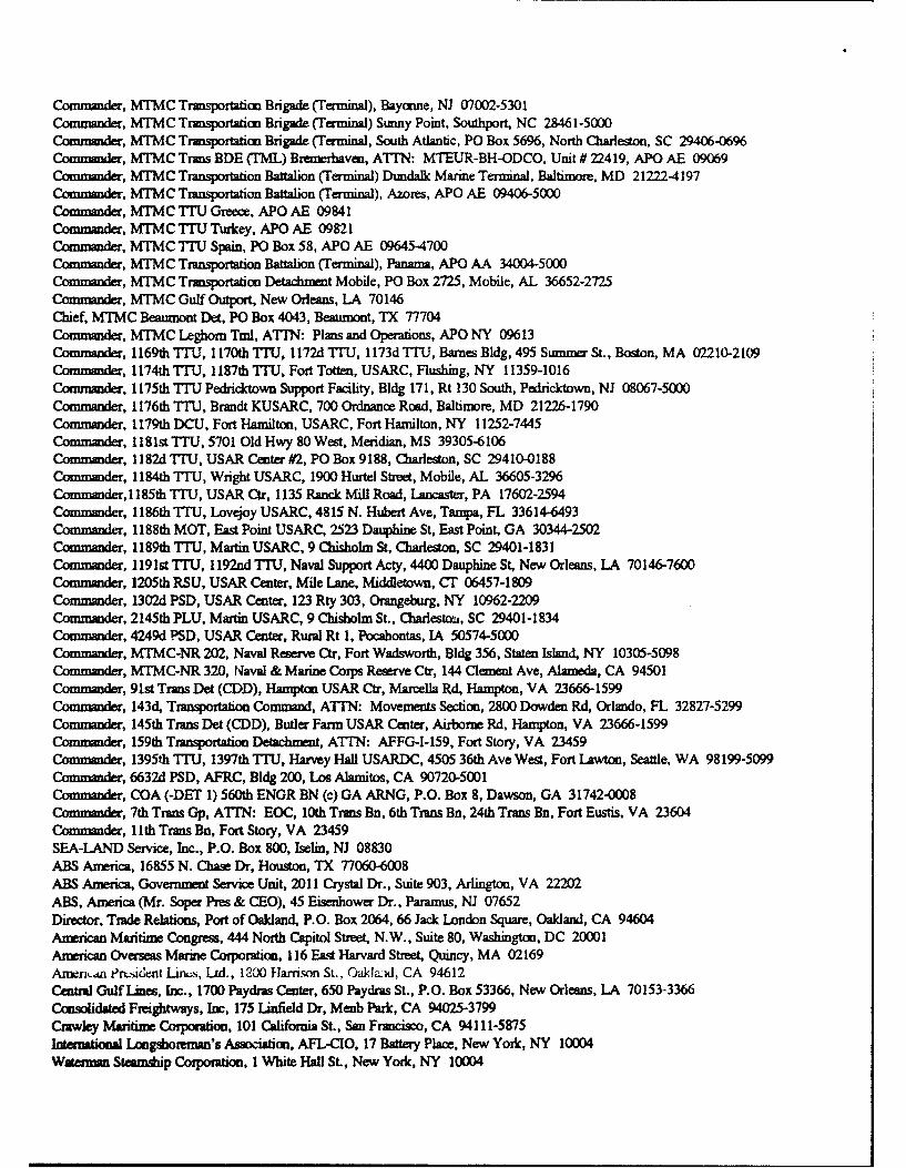
Commander, MTMC Transportation Brigade (Terminal), Bayonne, NJ 07002-5301Commander, MTMC Transportation Brigade (Terminal) Sunny Point, Southport, NC 28461-5000Commander, MTMC Transportation Brigade (Terminal, South Atlantic, PO Box 5696, North Charleston, SC 29406-0696Commander, MTMC Trans BDE (TML) Bremerhaven, ATTN: MTEUR-BH-ODCO, Unit # 22419, APO AE 09069Commander, MTMC Transportation Battalion (Terminal) Dundalk Marine Terminal, Baltimore, MD 212224197Commander, MTMC Transportation Battalion (Terminal), Azores, APO AE 09406-5000Commander, MTMC TTU Greece, APO AE 09841Commander, MTMC TTU Turkey, APO AE 09821Commander, MTMC TTU Spain, PO Box 58, APO AE 096454700Commander, MTMC Transporlation Battalion (Terminal), Panama, APO AA 34004-5000Commander, MTMC Transportation Detaclunet Mobile, PO Box 2725, Mobile, AL 36652-2725Commander, MTMC Gulf Outport, New Orleans, LA 70146Chief, MTMC Beaumont Det, PO Box 4043, Beaumont, TX 77704Commander, MTMC Leghorn Tml, ATTN: Plans and Operations, APO NY 09613Commander, 1169th TTU, 1170th TTU, 1172d TrU, 1173d TTU, Barnes Bldg, 495 Summer St., Boston, MA 02210-2109Commander, 1174th TTU, 1187th T'U, Fort Totten, USARC, Flushing, NY 11359-1016Commander, 1175th TrU Pedricktown Support Facility, Bldg 171, Rt 130 South, Pedricktown, NJ 08067-5000Commander, 1176th TTU, Brandt KUSARC, 700 Ordnance Road, Baltimore, MD 21226-1790Commander, 1179th DCU, Fort Hamilton, USARC, Fort Hamilton, NY 11252-7445Commander, 1l81st TTU, 5701 Old Hwy 80 West, Meridian, MS 39305-6106Commander, 1182d ITU, USAR Center #2, PO Box 9188, Charleston, SC 29410,0188Commander, 1184th T7U, Wright USARC, 1900 Hurtel Street, Mobile, AL 36605-3296Commander, I 185th TTU, USAR Ctr, 1135 Ranck Mill Road, Lancaster, PA 17602-2594Commander, 1186th TTU, Lovejoy USARC, 4815 N. Hubert Ave, Tampa, FL 33614-6493Commander, 1188th MOT, East Point USARC, 2523 Dauphine St, East Point, GA 30344-2502Commander, 1189th TTU, Martin USARC, 9 Chisholm St, Charleston, SC 29401-1831Commander, 1191st TTU, 1192nd TTU, Naval Support Acty, 4400 Dauphine St, New Orleans, LA 70146-7600Commander, 1205th RSU, USAR Center, Mile Lane, Middletown, CT 06457-1809Commander, 1302d PSD, USAR Center, 123 Rty 303, Orangeburg, NY 10962-2209Commander, 2145th PLU, Martin USARC, 9 Chisholm St., Charestau, SC 29401-1834Commander, 4249d PSD, USAR Center, Rural Rt 1, Pocahontas, IA 50574-5000Commander, MTMC-NR 202, Naval Reserve Ctr, Fort Wadsworth, Bldg 356, Staten Island, NY 10305-5098Commander, MTMC-NR 320, Naval & Marine Corps Reserve Ctr, 144 Clement Ave, Alameda, CA 94501Commander, 91st Trans Det (CDD), Hampton USAR Ctr, Marcella Rd, Hampton, VA 23666-1599Commander, 143d, Transportation Command, ATTN: Movements Section, 2800 Dowden Rd, Orlando, FL 32827-5299Commander, 145th Trans Det (CDD), Butler Farm USAR Center, Airborne Rd, Hampton, VA 23666-1599Commander, 159th Transportation Detachment, ATTN: AFFG-I-159, Fort Story, VA 23459Commander, 1395th 'TTU, 1397th TTU, Harvey Hall USARDC, 4505 36th Ave West, Fort Lawton, Seattle, WA 98199-5099Commander, 6632d PSD, AFRC, Bldg 200, Los Alamitos, CA 90720-5001Commander, COA (-DET 1) 560th ENGR BN (c) GA ARNG, P.O. Box 8, Dawson, GA 31742-0008Commander, 7th Tram Gp, ATTN: EOC, 10th Trans Bn, 6th Trans Bn, 24th Tram Bn, Fort Eustis, VA 23604Commander, 11 th Trans Bn, Fort Story, VA 23459SEA-LAND Service, Inc., P.O. Box 800, Iselin, NJ 08830ABS America, 16855 N. Chase Dr, Houston, TX 77060-6008ABS America, Government Service Unit, 2011 Crystal Dr., Suite 903, Arlington, VA 22202ABS, America (Mr. Soper Pres & CEO), 45 Eisenhower Dr., Paramus, NJ 07652Director, Trade Relations, Port of Oakland, P.O. Box 2064, 66 Jack London Square, Oakland, CA 94604American Maritime Congress, 444 North Capitol Street, N.W., Suite 80, Washington, DC 20001American Overseas Marine Corporation, 116 East Harvard Street, Quincy, MA 02169Amenn•a Prt.sident Lin,.-, Ltd., 1200 Harrison St., Oakkl"d, CA 94612Central Gulf Lines, Inc., 1700 Paydras Center, 650 Paydras St., P.O. Box 53366, New Orleans, LA 70153-3366Comfidated Freightways, Inc, 175 Linfield Dr, Menb Park, CA 94025-3799Crawley Maritime Corporation, 101 California St., San Francisco, CA 94111-5875International Longshoreman's Association, AFL-CIO, 17 Battery Place, New York, NY 10004Waterman Steamship Corpomtion, I White Hall St., New York, NY 10004
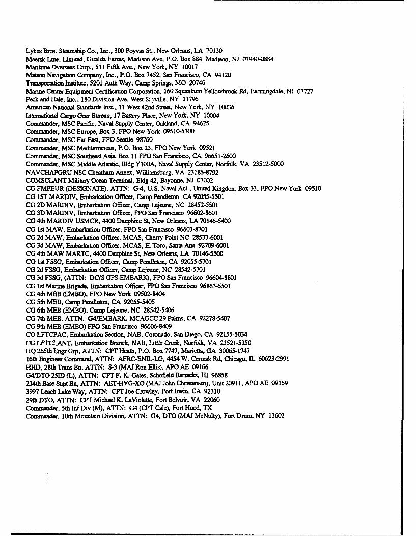
Lykes Bros. Steamship Co., Inc., 300 Poyvas St., New Orleans, LA 70130Maersk Line, Limited, Giralda Farms, Madison Ave, P.O. Box 884, Madison, NJ 07940-0884Maritime Overseas Corp., 511 Fifth Ave., New York, NY 10017Matson Navigation Company, Inc., P.O. Box 7452, San Francisco, CA 94120Tramportalion Institute, 5201 Auth Way, Camp Springs, MO 20746Marine Center Equipment Certification Corporation, 160 Squankum Yellowbrook Rd, Farmingdale, NJ 07727Peck and Hale, Inc., 180 Division Ave, West & ,ville, NY 11796American National Standards Inst., 11 West 42nd Street, New York, NY 10036International Cargo Gear Bureu, 17 Battery Place, New York, NY 10004Commander, MSC Pacific, Naval Supply Center, Oakland, CA 94625Commander, MSC Europe, Box 3, FPO New York 09510-5300Commander, MSC Far East, FPO Seattle 98760Commander, MSC Mediterranean, P.O. Box 23, FPO New York 09521Commander, MSC Southeast Asia, Box 11 FPO San Francisco, CA 96651-2600Commander, MSC Middle Atlantic, Bldg Y100A, Naval Supply Center, Norfolk, VA 23512-5000NAVCHAPGRU NSC Cheatham Annex, Williamsburg, VA 23185-8792COMSCLANT Military Ocean Terminal, Bldg 42, Bayonne, NJ 07002CG FMFEUR (DESIGNATE), ATIN: G-4, U.S. Naval Act., United Kingdon, Box 33, FPO New York 09510CG 1ST MARDIY, Embarkation Officer, Camp Pendleton, CA 92055-5501CG 2D MARDIV, Embarkation Officer, Camp Lejeune, NC 28452-5501CG 3D MARDIV, Embarkation Officer, FPO San Francisco 96602-8601CG 4th MARDIV USMCR, 4400 Dauphine St, New Orleans, LA 70146-5400CG 1st MAW, Embarkation Officer, FPO San Francisco 96603-8701CG 2d MAW, Embarkation Officer, MCAS, Cherry Point NC 28533-6001CG 3d MAW, Embarkation Officer, MCAS, El Toro, Santa Ana 92709-6001CG 4th MAW MARTC, 4400 Dauphine St, New Orleans, LA 70146-5500CO 1st FSSG, Embarkation Officer, Camp Pendleton, CA 92055-5701CG 2d FSSG, Embarkation Officer, Camp Lejeune, NC 28542-5701CG 3d FSSG, (ATITN: DC/S OPS-EMBARK), FPO San Francisco 96604-8801CO 1st Marine Brigade, Embarkation Officer, FPO San Francisco 96863-5501CG 4th MEB (EMBO), FPO New York 09502-8404CG 5th MEB, Camp Pendleton, CA 92055-5405CG 6th MEB (EMBO), Camp Lejeune, NC 28542-5406CG 7th MEB, ATTN: G4/EMBARK, MCAGCC 29 Palms, CA 92278-5407CG 9th MEB (EMBO) FPO San Francisco 96606-8409CO LFTCPAC, Embarkation Section, NAB, Coronado, San Diego, CA 92155-5034CG LFTCLANT, Embarkation Branch, NAB, Little Creek, Norfolk, VA 23521-5350HQ 265th Engr Grp, ATTN: CPT Heath, P.O. Box 7747, Marietta, GA 30065-174716th Engineer Command, ATTN: AFRC-ENIL-LG, 4454 W. Cermak Rd, Chicago, IL 60623-2991HHD, 28th Trans Bn, ATTN: S-3 (MAI Ron Ellis), APO AE 09166G4fDTO 251D (L), ATTN: CPT F. K. Gates, Schofield Barracks, HI 96858234th Base Supt Bn, ATTN: AET-HVG-XO (MAJ John Christensen), Unit 2091 1, APO AE 091693997 Leach Lake Way, ATTN: CPT Joe Crowley, Fort Irwin, CA 9231029th DTO, ATTN: CPT Michael K. LaViolette, Fort Belvoir, VA 22060Commander, 5th Inf Div (M), ATTN: G4 (CPT Cale), Fort Hood, TXCommander, 10th Mountain Division, AMTN: G4, DTO (MAJ McNulty), Fort Drum, NY 13602