Embed Size (px)
Citation preview
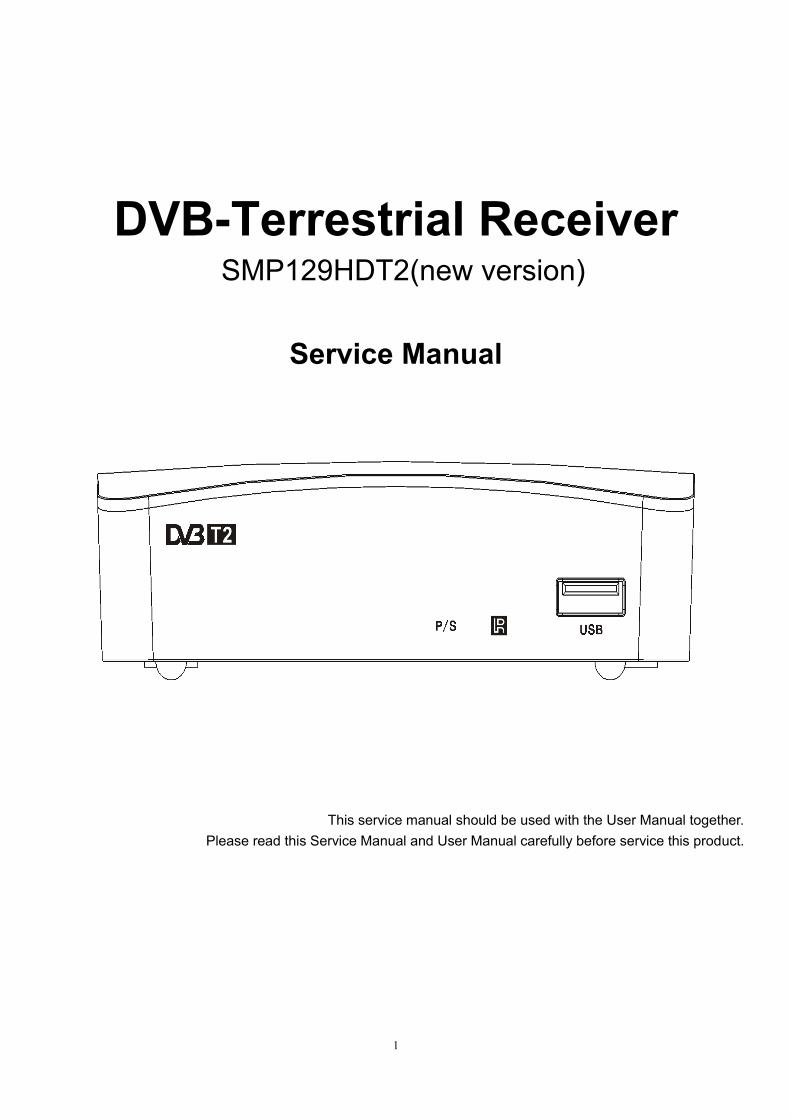
1
DVB-Terrestrial Receiver SMP129HDT2(new version)
Service Manual
This service manual should be used with the User Manual together.
Please read this Service Manual and User Manual carefully before service this product.
2
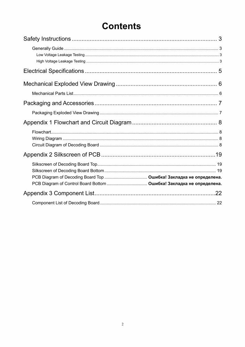
Contents
Safety Instructions ......................................................................................... 3
Generally Guide .................................................................................................................................. 3
Low Voltage Leakage Testing ................................................................................................................................. 3
High Voltage Leakage Testing ................................................................................................................................ 3
Electrical Specifications ................................................................................. 5
Mechanical Exploded View Drawing .............................................................. 6
Mechanical Parts List .......................................................................................................................... 6
Packaging and Accessories ........................................................................... 7
Packaging Exploded View Drawing .................................................................................................... 7
Appendix 1 Flowchart and Circuit Diagram .................................................... 8
Flowchart ............................................................................................................................................. 8
Wiring Diagram ................................................................................................................................... 8
Circuit Diagram of Decoding Board .................................................................................................... 8
Appendix 2 Silkscreen of PCB ......................................................................19
Silkscreen of Decoding Board Top .................................................................................................... 19
Silkscreen of Decoding Board Bottom .............................................................................................. 19
PCB Diagram of Decoding Board Top .................................... Ошибка! Закладка не определена.
PCB Diagram of Control Board Bottom .................................. Ошибка! Закладка не определена.
Appendix 3 Component List ..........................................................................22
Component List of Decoding Board .................................................................................................. 22

3
Safety Instructions
Generally Guide
1. Please check electric circuits before maintenance and change the damaged or over heated components if
short-circuit has been found.
2. Please check all protective devices have been installed well after maintenance, such as insulation covering
and paper.
3. Please finish following electrical leakage tests after maintenance to avoid electric shock.
Low Voltage Leakage Testing
Take out power cord from an AC outlet and connect a length of wire between the two leads of the plug.
Use Gear R x 10K of the voltmeter to measure the resistance between shorted-out AC plug and exposed
metallic parts like screw cap, control shaft etc. which shall be infinite.
Picture 1
High Voltage Leakage Testing
As shown in Picture 1, connect a resistor of 1.5K, 10W and capacitor of 0.15 uF between exposed metallic
part and well grounded devices (water pipe etc.).
Plug power cord directly into the socket. Do not use insulated transformer to test.
Use 1000 Ohm/V or more sensitive voltmeter to measure AC voltage of the resistor.
Turn over the AC jack and plug into the socket again to iterate the inspection as above.
Inspect the voltage of the resistor between other exposed metallic parts and the earth in the same way.
Any parts’ voltage of the resistor should not over 0.75Vrms. A leakage testing machine with voltage over
2,500 V can also be used for this inspection in which case the electric leakage should not be over 0.5mA. When
the leakage exceeds that limit, electric shock may occur. Please check and repair again before hand it over to
users.
4. Protect Electrostatic-Sensitive Devices from Electrostatic Discharge
Some solid states made of semiconductors materials can be easily damaged by commonly static charges,
those components are usually called electrostatic-sensitive devices. Such like integrated circuits, laser diodes
and field effect devices. The following tips will help you to reduce the impacts on those components while
electrostatic discharging.
Please release static which build-up on human body before handling electrostatic-sensitive devices by using
grounded tools. The antistatic strap which can be found in the market will be a good choice.
4
Please install the electrostatic-sensitive devices on conductor products such as aluminum foil to prevent static
build-up after disassembling from this DVB-T receiver.
The soldering iron must be earthed while soldering and unsoldering the electrostatic-sensitive devices.
Only antistatic solder can be used for electrostatic-sensitive devices disassembly. The electrostatic-sensitive
devices will be damaged by static without ESD prevention solder while disassembling.
Do not use Freon Volatile which may damage the electrostatic-sensitive devices by discharging static.
Do not take the new electrostatic-sensitive devices from the antistatic protection package unless you are
ready for installation. (Most electrostatic-sensitive devices will be packed with anti-static foam, foil or similar
conductive materials. And a lead wire to prevent short circuit.)
Please contact the core or circuit parts of the device to be installed with ESD protection package before carry
out the new electrostatic-sensitive devices from it. And make sure no power supply on the device and remember
other precautions.
Try to reduce body movements while assembling or disassembling electrostatic-sensitive devices. (Clothes
made of fabrics will build-up static by attrition. Feet lifts up from floor will also build-up static.)
5
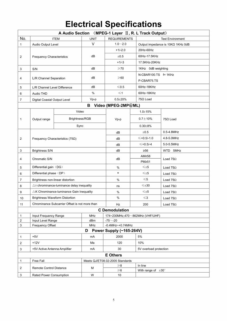
Electrical Specifications A Audio Section (MPEG-1 Layer Ⅱ, R. L Track Output)
No. ITEM UNIT REQUIREMENTS Test Environment
1 Audio Output Level V 1.0~2.0 Output impedance is 10KΩ 1KHz 0dB
2 Frequency Characteristics dB
+1/-2.0 20Hz-60Hz
0.5 60Hz-17.5KHz
+1/-3 17.5KHz-20KHz
3 S/N dB ≥70 1KHz 0dB weighting
4 L/R Channel Separation dB ≥60 N-CBAR100.TS f= 1KHz
P-CBAR75.TS
5 L/R Channel Level Difference dB ≤0.5 60Hz-18KHz
6 Audio THD % ≤1 60Hz-18KHz
7 Digital Coaxial Output Level Vp-p 0.520% 75Ω Load
B Video (MPEG-2MP@ML)
1 Output range
Video
Vp-p
1.015%
75Ω Load Brightness/RGB 0.7±10%
Sync 0.308%
2 Frequency Characteristics (75Ω)
dB 0.5 0.5-4.8MHz
dB ≤+0.5/-1.0 4.8-5.0MHz
dB ≤+0.5/-4 5.0-5.5MHz
3 Brightness S/N dB ≥56 WTD 5MHz
4 Chromatic S/N dB AM≥58
Load 75 PM≥51
5 Differential gain(DG) % ≤5 Load 75
6 Differential phase(DP) ° ≤5 Load 75
7 Brightness non-linear distortion % ≤5 Load 75
8 △τ chrominance-luminance delay inequality ns ≤30 Load 75
9 △K Chrominance-luminance Gain Inequality % ≤5 Load 75
10 Brightness Waveform Distortion % ≤3 Load 75
11 Chrominance Subcarrier Offset is not more than Hz 200 Load 75
C Demodulation
1 Input Frequency Range MHz 174~230MHz,470~862MHz (VHF/UHF)
2 Input Level Range dBm -75~-20
3 Frequency Offset MHz -0.4MHz~+0.74MHz
D Power Supply (~165-264V)
1 +5V mA 2000 5%
2 +12V Ma 120 10%
3 +5V Active Antenna Amplifier mA 30 5V overload protection
E Others
1 Free Fall Meets QJ/ET08.02-2005 Standards
2 Remote Control Distance M ≥8 In line
≥6 With range of 30°
3 Rated Power Consumption W 10
6
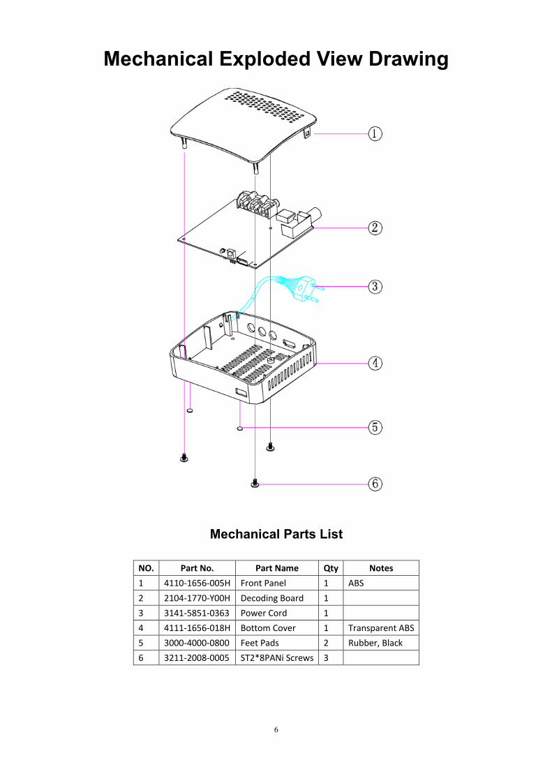
Mechanical Exploded View Drawing
Mechanical Parts List
NO. Part No. Part Name Qty Notes
1 4110-1656-005H Front Panel 1 ABS
2 2104-1770-Y00H Decoding Board 1
3 3141-5851-0363 Power Cord 1
4 4111-1656-018H Bottom Cover 1 Transparent ABS
5 3000-4000-0800 Feet Pads 2 Rubber, Black
6 3211-2008-0005 ST2*8PANi Screws 3
7
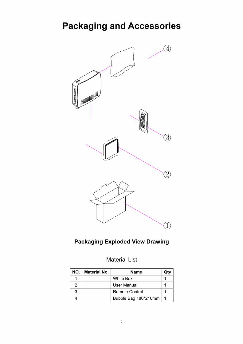
Packaging and Accessories
Packaging Exploded View Drawing
Material List
NO. Material No. Name Qty
1 White Box 1
2 User Manual 1
3 Remote Control 1
4 Bubble Bag 180*210mm 1

8
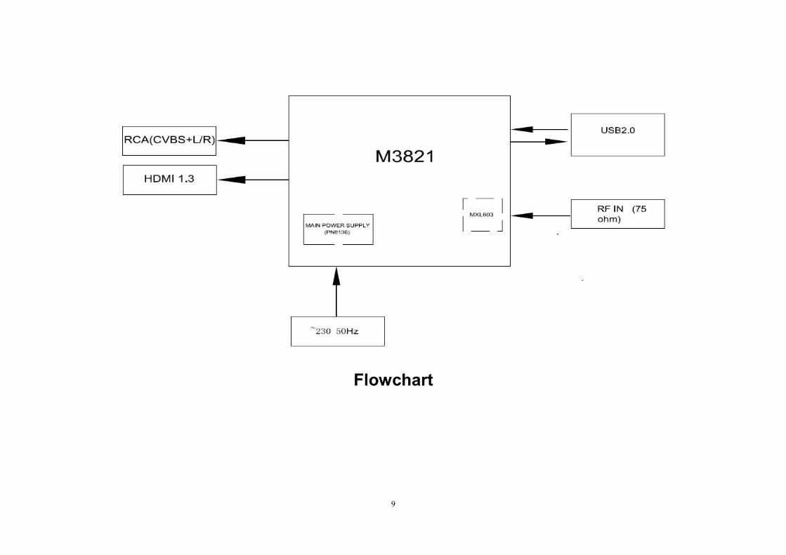
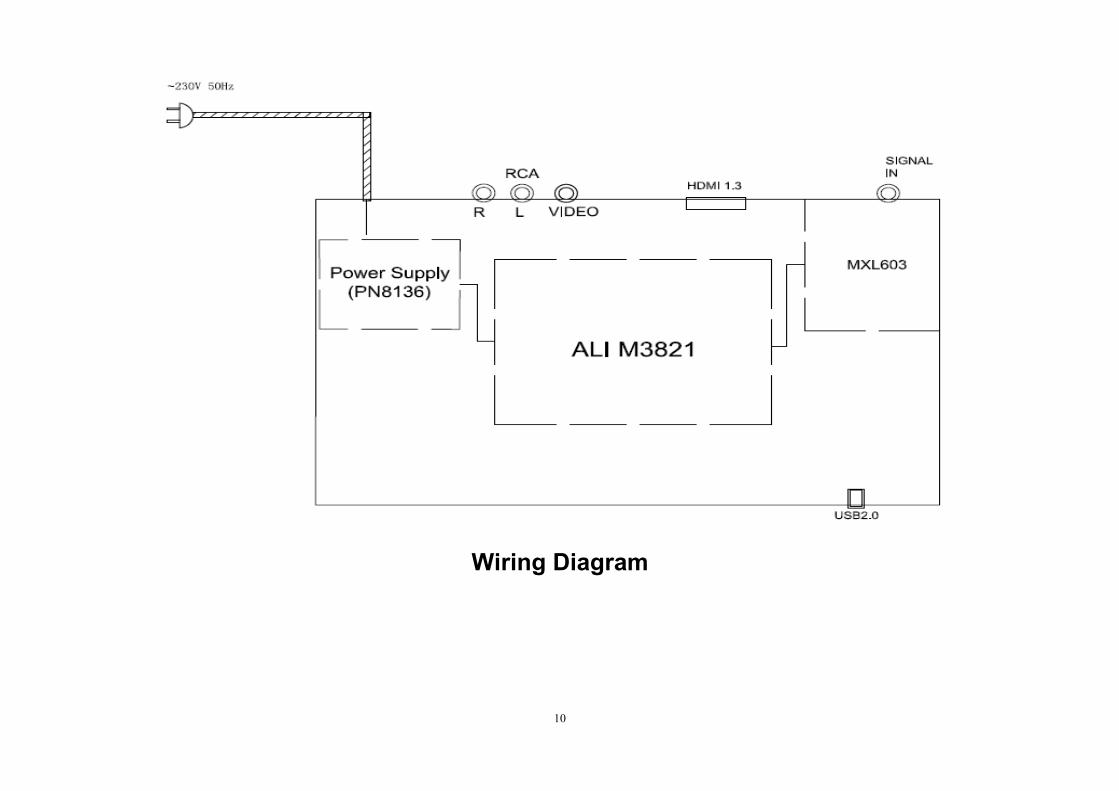
Appendix 1 Flowchart and Circuit Diagram
Flowchart
Wiring Diagram
Circuit Diagram of Decoding Board
9
Flowchart
10
Wiring Diagram
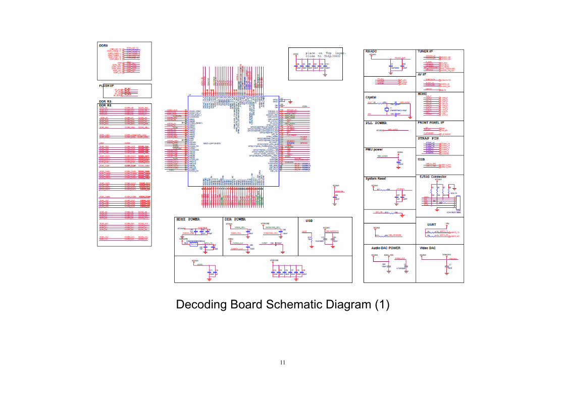
11
Decoding Board Schematic Diagram (1)
12
Decoding Board Schematic Diagram (2)
13
Decoding Board Schematic Diagram (3)
14
Decoding Board Schematic Diagram (4)
15
Decoding Board Schematic Diagram (5)
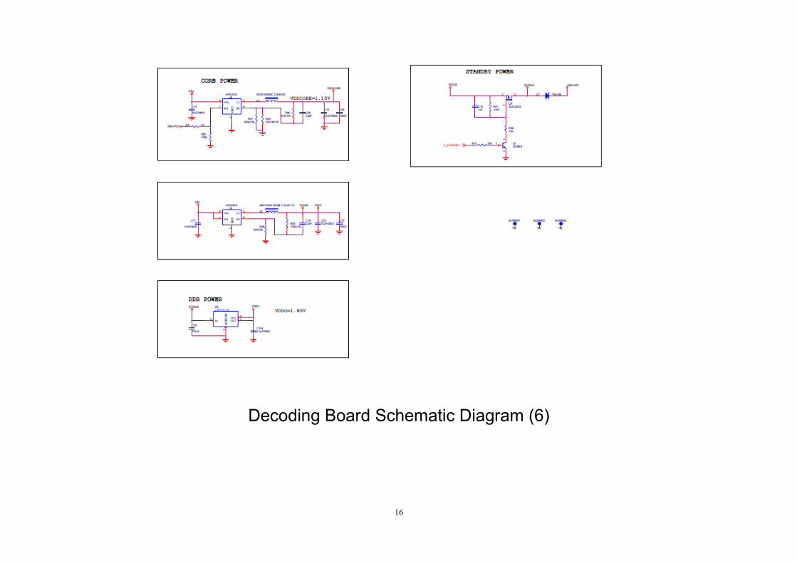
16
Decoding Board Schematic Diagram (6)

17
Power Board Schematic Diagram (1)
18
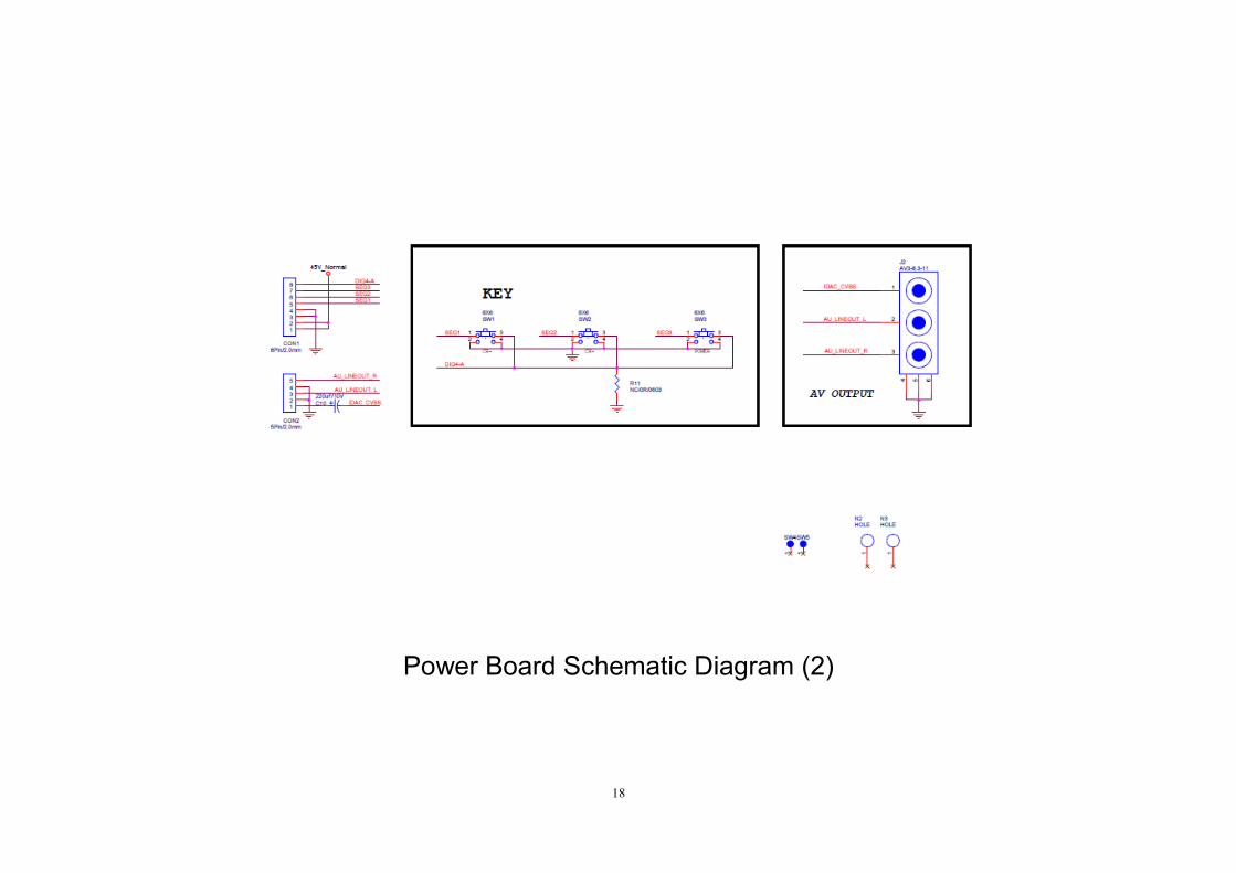
Power Board Schematic Diagram (2)
19
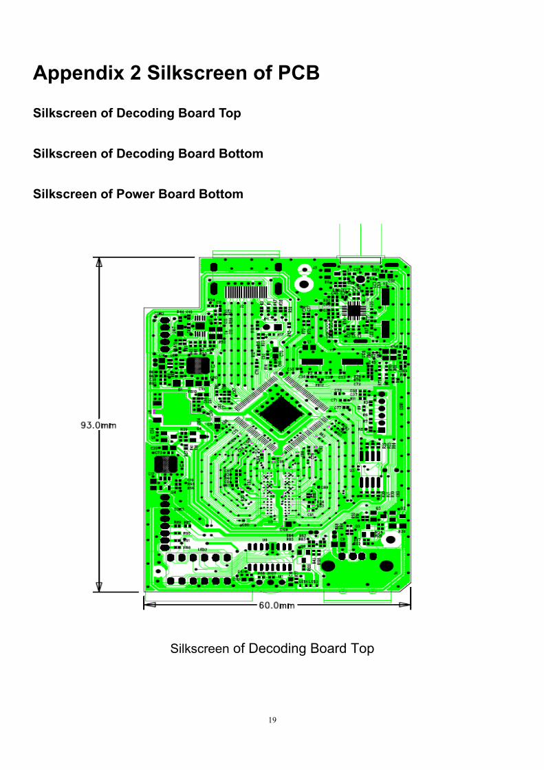
Appendix 2 Silkscreen of PCB
Silkscreen of Decoding Board Top
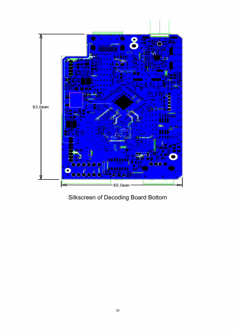
Silkscreen of Decoding Board Bottom
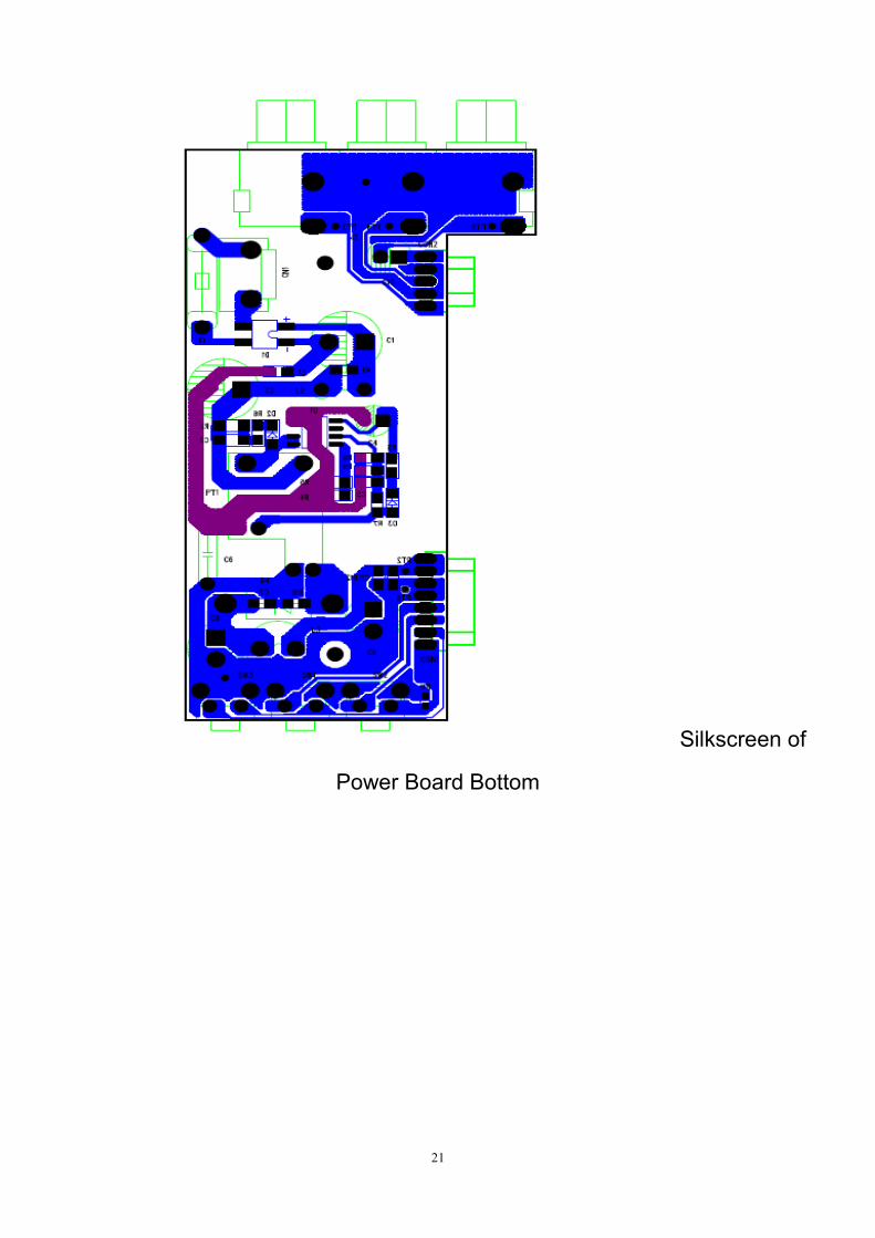
Silkscreen of Power Board Bottom
Silkscreen of Decoding Board Top
20
Silkscreen of Decoding Board Bottom
21
Silkscreen of
Power Board Bottom

22
Appendix 3 Component List
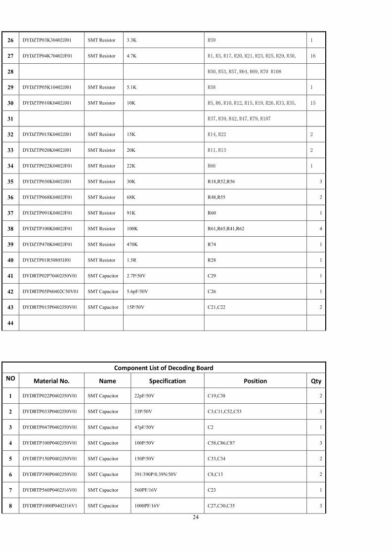
Component List of Decoding Board

23
Component List of Decoding Board
Component List
Component List of Decoding Board
NO
. Material No. Name Specification Position Qty
1 WJQTPBGAD3MM01 Shield Cover 0.3mm 1
2 JCQTHW00MYS83801 Receiver Head MYS-838 IR1 1
3 JCCZQTUSB0000001 USB Socket USB-A J1 1
4
5 WJQTSR20X20X1001 Heat Sink 20*20*10mm On the top of U1 1
6 JCZZWZ1X05W20001 Curved needle 1*5P*2.0mm CON2 1
7 FH=4.0mm,H=2.0mm PL=3.0mm
8 JCZZWZ1X08W20001 Curved needle 1*8P*2.0mm FH=4.0mm CON3 1
9 ,H=2.0mm PL=3.0mm 90°
10 WJQTPBPBZ09401 Tuner cover 0.3mm RF IN J3 1
11
12 DYDZTP000R0402JJ01 SMT Resistor 0R R49,R67,R68 3
13 DYDZTP05R10402JJ01 SMT Resistor 5.1R R44 1
14 DYDZTP010R0402JJ01 SMT Resistor 10R R77 1
15 DYDZTP033R0402JJ01 SMT Resistor 33R R2,R9 2
16 DYDZTP075R0402JJ01 SMT Resistor 75R R81 1
17 DYDZTP100R0402JJ01 SMT Resistor 100R R71,R72,R88 3
18 DYDZTP680R0402JJ01 SMT Resistor 680R R109 1
19 DYDZTP200R0402JJ01 SMT Resistor 200R R80 1
20 DYDZTP330R0402JJ01 SMT Resistor 330R R45,R54,R73,R75 4
21
22 DYDZTP470R0402JJ01 SMT Resistor 470R R16 1
23 DYDZTP001K0402JF01 SMT Resistor 1K R38,R40 2
24 DYDZTP001K0402JJ01 SMT Resistor 1K R4,R24,R27,R34,R43,R46,R76 7
25 DYDZTP01K20402JJ01 SMT Resistor 1.2K 1/16W R51 1
24
26 DYDZTP03K30402JJ01 SMT Resistor 3.3K R59 1
27 DYDZTP04K70402JF01 SMT Resistor 4.7K R1,R3,R17,R20,R21,R23,R25,R29,R30, 16
28 R50,R53,R57,R64,R69,R70 R108
29 DYDZTP05K10402JJ01 SMT Resistor 5.1K R58 1
30 DYDZTP010K0402JJ01 SMT Resistor 10K R5,R6,R10,R12,R15,R19,R26,R33,R35, 15
31 R37,R39,R42,R47,R79,R107
32 DYDZTP015K0402JJ01 SMT Resistor 15K R14,R22 2
33 DYDZTP020K0402JJ01 SMT Resistor 20K R11,R13 2
34 DYDZTP022K0402JF01 SMT Resistor 22K R66 1
35 DYDZTP030K0402JJ01 SMT Resistor 30K R18,R52,R56 3
36 DYDZTP068K0402JF01 SMT Resistor 68K R48,R55 2
37 DYDZTP091K0402JF01 SMT Resistor 91K R60 1
38 DYDZTP100K0402JF01 SMT Resistor 100K R61,R65,R41,R62 4
39 DYDZTP470K0402JF01 SMT Resistor 470K R74 1
40 DYDZTP01R50805JJ01 SMT Resistor 1.5R R28 1
41 DYDRTP02P70402J50V01 SMT Capacitor 2.7P/50V C29 1
42 DYDRTP05P60402C50V01 SMT Capacitor 5.6pF/50V C26 1
43 DYDRTP015P0402J50V01 SMT Capacitor 15P/50V C21,C22 2
44
Component List of Decoding Board
NO
. Material No. Name Specification Position Qty
1 DYDRTP022P0402J50V01 SMT Capacitor 22pF/50V C19,C38 2
2 DYDRTP033P0402J50V01 SMT Capacitor 33P/50V C3,C11,C52,C53 3
3 DYDRTP047P0402J50V01 SMT Capacitor 47pF/50V C2 1
4 DYDRTP100P0402J50V01 SMT Capacitor 100P/50V C58,C86,C87 3
5 DYDRTP150P0402J50V01 SMT Capacitor 150P/50V C33,C34 2
6 DYDRTP390P0402J50V01 SMT Capacitor 391/390P/0.39N/50V C8,C13 2
7 DYDRTP560P0402J16V01 SMT Capacitor 560PF/16V C23 1
8 DYDRTP1000P0402J16V1 SMT Capacitor 1000PF/16V C27,C30,C35 3
25
9 DYDRTP04N70402K50V01 SMT Capacitor 4.7nF/50V C28 1
10 DYDRTP010N0402M50V01 SMT Capacitor 103/10N/0.01uF/50V C46,C50,C62,C90 4
11 DYDRTP330N0402K10V01 SMT Capacitor 334/330N/0.33U/10V C6,C10 2
12 DYDRTP100N0402M16V01 SMT Capacitor 104/100N/0.1U/16V
C7,C24,C25,C31,C32,C36,C37,C43,C44,C45,C
48,C49,C54,C55,C56,C59,C60,C63,C64,C65,C
66,C68,C69,C71,C73,C74,C75,C76,C77,C78,C
79,C80,C83,C84,C88,C89,C91,C92,C93,C94,C
95,C96,C97,C99,C100,C101,C105
47
13 DYDRTP001U0402M16V01 SMT Capacitor 1UF/16V C18,C42,C47,C57,C61,C67,C72 7
14 DYDRTP02U20603M10V01 SMT Capacitor 2.2uF/10V C16,C104 2
15 DYDRTP02U20805M10V01 SMT Capacitor 2.2uF/10V C4,C12,C107 3
16 DYDRTP04U70805M10V01 SMT Capacitor 4.7UF/10V C5 1
17 DYDRTP010U0805M16V01 SMT Capacitor 10U/16V C1,C9,C14,C15,C17,C20,C51,C70,C106,C108 10
18 DYDGTP012N0402JJ01 Inductance 12nH/ MLG1005 L1 1
19 DYDGTP033N0402JJ01 Inductance 33nH/ MLG1005 L2,L5 2
20 DYDGTP150N0603JJ02 Inductance 150nH L4 1
21 DYDGGL02U2SMD4X402 Inductance MD43-2R2MC,2.2UH,2.6A L6 1
22 DYDGGL02U2SMD4X403 Inductance 2.2UH±20%, L6 1
23 2.6A,GDCD4532-2R2MTF
24
25 DYDGGL03U3SMD4X402 Inductance 3.3uH±20%, L3 1
26 2.5A,GDCD4532-3R3MTF
27
28 DYCZTP330R0402K0A102 chip Bead 0402,330Ω,100mHz,100mA, FB12 1
29 DYCZTP330R0603K0A201 chip Bead 330Ω,100mHz,200mA, FB3,FB4,FB10 3
30 DYCZTP330R0805K1A501 chip Bead 330Ω,100mHz,1.5A, FB2 1
31 DYEJZLT0LL4148LL3401 Diode LL4148 D1 1
32 DYEJFGTPRED0603002 Diode KF0603R1412B LED1 1
33 DYEJFGTPGREEN0603002 Diode KF0603PG1412B LED3 1
34 DYEJSDBAV99SOT230001 Diode BAV99(LBAV99LT1G) D2 1
35 DYJZWYF000016M05 Crystal 16MHZ, 20PF, Y2 1
36 DYJZWYT000027M01 Crystal 27MHZ Y1 1
26
37 DYSJNPMMBT3904SO230
1 Triode(NPN)
MMBT3904/LMBT3904LT1G(
NPN) Q1,Q3,Q6 3
38
39
40
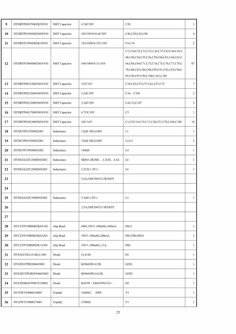
Component List of Decoding Board
NO
. Material No. Name Specification Position Qty
1 DYSJPNMMBT3906SO230
1 Triode(PNP)
MMBT3906/LMBT3906LT1G(P
NP) Q5 1
2 DYSJ00TS85500SOT01 Triode S8550 Q2 1
3 DYSJPNT0008550SO2301 Triode L8550HQLT1G Q2 1
4 DYSJMSSI2323DSST2301 Triode SI2323DS Q4 1
5 DYSJMSWTM4PE020SOT
01 MOS tube WTM4PE02EA Q4 1
6 DYXPQTT0LD11170SOP01 CHIP IC LD1117-1.8V ( OR
LM1117-1.8V) U8 1
7 DYXPAS1117LX1D8V01 CHIP IC(LDO) AS1117L-1.8 U8 1
8 DYXPWY0LC1117SOT03 CHIP IC LC1117-1.8 U8 1
9 DYXPDYJY1117180SOT01 CHIP IC(POWER
(LDO)) JY1117-1.8V,SOT223, U8 1
10 DYXPM14D5121632BGA0
2 CHIP IC
M14D5121632A-1.8BG2K,FBG
A-84 U5 1
11 DYXPA3R12E40FBGA01 CHIP IC(DDR2)
A3R12E40CBF-AH
IC-84P-FBGA-DDR2
(64M)(zentel)
U5 1
12 DYXPNT5TU32M16DG02 CHIP IC(DDR2) NT5TU32M16DG-BE(64MB) U5 1
13 DYXPDYAPS2408E0SOT0
1
CHIP IC(DC-DC
POWER) APS2408ES5-ADJ U4 1
14 DYXPDYAPS2420E0SOT0
1
CHIP IC(DC-DC
POWER) APS2420TBER-ADJ SOT23-6L U6 1
15 DYXPM3821LQFP12801 MAIN CHIP
IC(CPU)
M3821-ALAAA(WITHOUT
DOBLY) U1 1
16 DYXPMXL6080QFN01 CHIP IC MXL608-AG U7 1
17 DYXPSGM8905MSOP001 CHIP IC SGM8905YPMS10G/TR U2 1
18 DYXPGD25Q32CSOP801 CHIP IC(FLASH) GD25Q32CSIG (4MB) U3 1

27
19 JCCZHDMISOCKET01 HDMI Socket HDMI SOCKET,:JCJ-CZL-018 J2 1
20
21
22
23
24
25
26
27
28
29
30
31
32
33
34
35
36
37
38
39
40
41
Component List of POWER Board
NO
. Material No. Name Specification Position Qty
1 DYDRDJ04U70000MK4005 Capacitor 4.7UF/400V,105° C1 1
2 DYDRDJ010U0000M50V01 Capacitor 106/10U/50V C4 1
3 DYDRDJ010U0000MK4005 Capacitor 10UF/400V,105°, C2 1
28
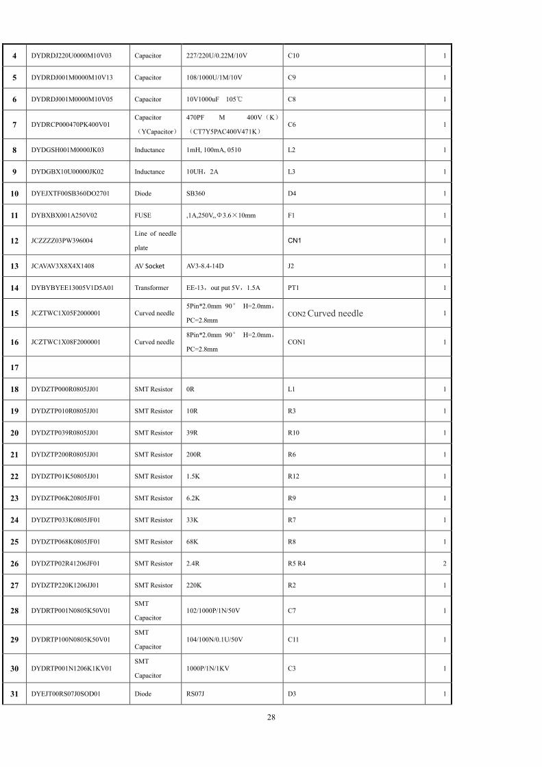
4 DYDRDJ220U0000M10V03 Capacitor 227/220U/0.22M/10V C10 1
5 DYDRDJ001M0000M10V13 Capacitor 108/1000U/1M/10V C9 1
6 DYDRDJ001M0000M10V05 Capacitor 10V1000uF 105℃ C8 1
7 DYDRCP000470PK400V01 Capacitor
(YCapacitor)
470PF M 400V(K)
(CT7Y5PAC400V471K) C6 1
8 DYDGSH001M0000JK03 Inductance 1mH, 100mA, 0510 L2 1
9 DYDGBX10U00000JK02 Inductance 10UH,2A L3 1
10 DYEJXTF00SB360DO2701 Diode SB360 D4 1
11 DYBXBX001A250V02 FUSE ,1A,250V,,Φ3.6×10mm F1 1
12 JCZZZZ03PW396004 Line of needle
plate CN1 1
13 JCAVAV3X8X4X1408 AV Socket AV3-8.4-14D J2 1
14 DYBYBYEE13005V1D5A01 Transformer EE-13,out put 5V,1.5A PT1 1
15 JCZTWC1X05F2000001 Curved needle 5Pin*2.0mm 90° H=2.0mm,
PC=2.8mm CON2 Curved needle 1
16 JCZTWC1X08F2000001 Curved needle 8Pin*2.0mm 90° H=2.0mm,
PC=2.8mm CON1 1
17
18 DYDZTP000R0805JJ01 SMT Resistor 0R L1 1
19 DYDZTP010R0805JJ01 SMT Resistor 10R R3 1
20 DYDZTP039R0805JJ01 SMT Resistor 39R R10 1
21 DYDZTP200R0805JJ01 SMT Resistor 200R R6 1
22 DYDZTP01K50805JJ01 SMT Resistor 1.5K R12 1
23 DYDZTP06K20805JF01 SMT Resistor 6.2K R9 1
24 DYDZTP033K0805JF01 SMT Resistor 33K R7 1
25 DYDZTP068K0805JF01 SMT Resistor 68K R8 1
26 DYDZTP02R41206JF01 SMT Resistor 2.4R R5 R4 2
27 DYDZTP220K1206JJ01 SMT Resistor 220K R2 1
28 DYDRTP001N0805K50V01 SMT
Capacitor 102/1000P/1N/50V C7 1
29 DYDRTP100N0805K50V01 SMT
Capacitor 104/100N/0.1U/50V C11 1
30 DYDRTP001N1206K1KV01 SMT
Capacitor 1000P/1N/1KV C3 1
31 DYEJT00RS07J0SOD01 Diode RS07J D3 1

29
32 DYEJZLT0LB10SSOPA01 Rectifier LB10S D1 1
33 DYXPPN8368SOP701 CHIP
IC( power) PN8368SSC-R1 U1 1
34 DYEJZLTD71KV1A0SOD01 Diode D7,1000V,1A D2 1
35
36
37
38
39