Embed Size (px)
Citation preview
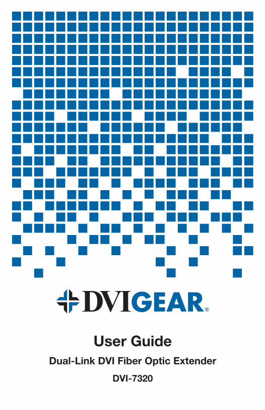
User GuideDual-Link DVI Fiber Optic Extender
DVI-7320
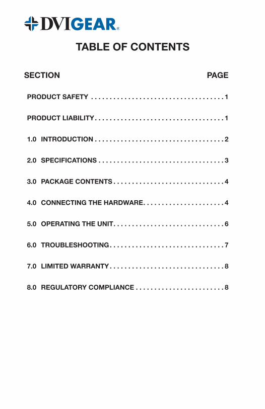
TABLE OF CONTENTS
SECTION PAGE
PRODUCT SAFETY . . . . . . . . . . . . . . . . . . . . . . . . . . . . . . . . . . . . 1
PRODUCT LIABILITY . . . . . . . . . . . . . . . . . . . . . . . . . . . . . . . . . . . 1
1.0 INTRODUCTION . . . . . . . . . . . . . . . . . . . . . . . . . . . . . . . . . . . 2
2.0 SPECIFICATIONS . . . . . . . . . . . . . . . . . . . . . . . . . . . . . . . . . . 3
3.0 PACKAGE CONTENTS . . . . . . . . . . . . . . . . . . . . . . . . . . . . . . 4
4.0 CONNECTING THE HARDWARE . . . . . . . . . . . . . . . . . . . . . . 4
5.0 OPERATING THE UNIT . . . . . . . . . . . . . . . . . . . . . . . . . . . . . . 6
6.0 TROUBLESHOOTING . . . . . . . . . . . . . . . . . . . . . . . . . . . . . . . 7
7.0 LIMITED WARRANTY . . . . . . . . . . . . . . . . . . . . . . . . . . . . . . . 8
8.0 REGULATORY COMPLIANCE . . . . . . . . . . . . . . . . . . . . . . . . 8
-1-
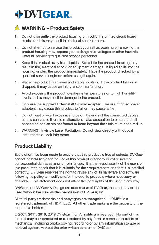
WARNING – Product Safety
1. Do not dismantle the product housing or modify the printed circuit board module as this may result in electrical shock or burn.
2. Do not attempt to service this product yourself as opening or removing the product housing may expose you to dangerous voltages or other hazards. Refer all servicing to qualified service personnel.
3. Keep this product away from liquids. Spills into the product housing may result in fire, electrical shock, or equipment damage. If liquid spills into the housing, unplug the product immediately. Have the product checked by a qualified service engineer before using it again.
4. Place the product in an even and stable location. If the product falls or is dropped, it may cause an injury and/or malfunction.
5. Avoid exposing the product to extreme temperatures or to high humidity levels as this may result in damage to the product.
6. Only use the supplied External AC Power Adapter. The use of other power adapters may cause this product to fail or may cause a fire.
7. Do not twist or exert excessive force on the ends of the connected cables as this can cause them to malfunction. Take precaution to ensure that all connected cables are not forced to bend beyond their minimum bend radius.
8. WARNING: Invisible Laser Radiation. Do not view directly with optical instruments or look into beam.
Product Liability
Every effort has been made to ensure that this product is free of defects. DVIGear cannot be held liable for the use of this product or for any direct or indirect consequential damages arising from its use. It is the responsibility of the users of this product to check that it is suitable for their requirements and that it is installed correctly. DVIGear reserves the right to revise any of its hardware and software following its policy to modify and/or improve its products where necessary or desirable. This statement does not affect the legal rights of the user in any way.
DVIGear and DVIGear & Design are trademarks of DVIGear, Inc. and may not be used without the prior written permission of DVIGear, Inc.
All third-party trademarks and copyrights are recognized. HDMI™ is a registered trademark of HDMI LLC. All other trademarks are the property of their respective holders.
© 2007, 2011, 2016, 2018 DVIGear, Inc. All rights are reserved. No part of this manual may be reproduced or transmitted by any form or means, electronic or mechanical, including photocopying, recording or by any information storage or retrieval system, without the prior written consent of DVIGear.
-2-
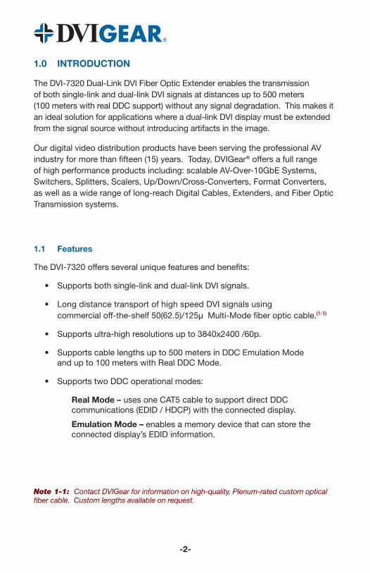
1.0 INTRODUCTION
The DVI-7320 Dual-Link DVI Fiber Optic Extender enables the transmission of both single-link and dual-link DVI signals at distances up to 500 meters (100 meters with real DDC support) without any signal degradation. This makes it an ideal solution for applications where a dual-link DVI display must be extended from the signal source without introducing artifacts in the image.
Our digital video distribution products have been serving the professional AV industry for more than fifteen (15) years. Today, DVIGear® offers a full range of high performance products including: scalable AV-Over-10GbE Systems, Switchers, Splitters, Scalers, Up/Down/Cross-Converters, Format Converters, as well as a wide range of long-reach Digital Cables, Extenders, and Fiber Optic Transmission systems.
1.1 Features
The DVI-7320 offers several unique features and benefits:
• Supports both single-link and dual-link DVI signals.
• Long distance transport of high speed DVI signals using commercial off-the-shelf 50(62.5)/125µ Multi-Mode fiber optic cable.(1-1)
• Supports ultra-high resolutions up to 3840x2400 /60p.
• Supports cable lengths up to 500 meters in DDC Emulation Mode and up to 100 meters with Real DDC Mode.
• Supports two DDC operational modes:
Real Mode – uses one CAT5 cable to support direct DDC communications (EDID / HDCP) with the connected display.
Emulation Mode – enables a memory device that can store the connected display’s EDID information.
Note 1-1: Contact DVIGear for information on high-quality, Plenum-rated custom optical fiber cable. Custom lengths available on request.
-3-
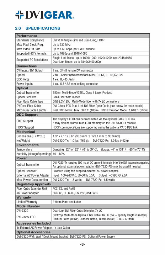
2.0 SPECIFICATIONS
PerformanceStandards Compliance DVI v1.0 (Single-Link and Dual-Link), HDCPMax. Pixel Clock Freq. Up to 330 MHzMax. Video Bit Rate Up to 1.65 Gbps. per TMDS channelSupported HDTV Formats Up to 1080p and 2048x1080
Supported PC ResolutionsSingle-Link Mode: up to 1600x1200, 1920x1200, and 2048x1080 Dual-Link Mode: up to 3840x2400 /60p
ConnectionsDVI Input / DVI Output 1 ea. 24+5 female DVI connectorOptical 7 ea. LC fiber optic connectors (Clock, R1, G1, B1, R2, G2, B2)DDC Ports 1 ea. RJ-45 JackPower Inputs 1 ea. 5.5 / 2.5 mm locking connectorOpticalOptical Transmitter 850nm Multi-Mode VCSEL, Class 1 Laser ProductOptical Receiver GaAs PIN Photo DiodesFiber Optic Cable Type 50 (62.5)/125µ Multi-Mode fiber with 7x LC connectorsDVIGear Fiber Cable DVI-23xxx-FOD Dual-Link DVI Fiber Optic Cable (see below for more details)Maximum Cable Length Real EDID Mode: Max. 328 ft. (100m); EDID Emulation Mode: 1,640 ft. (500m)DDC Support
EDID SupportThe display’s EDID can be transmitted via the optional CAT5 DDC link. It may also be stored in an EDID memory on the DVI-7320-TX module.
HDCP Support HDCP communications are supported using the optional CAT5 DDC link.MechanicalDimensions (H x W x D) 1.3” x 7.1” x 3.6” (33.3 mm x 179.1 mm x 90.3 mm)Net Weight DVI-7320-Tx: 1.0 lbs. (462 g); DVI-7320-Rx: 1.0 lbs. (462 g)Environmental Temperature Operating: 32° to 122° F ( 0° to 50° C ); Storage: -4° to 158° F ( -20° to 70° C )Humidity (storage/operating) 10 – 80%Power
Optical TransmitterDVI-7320-Tx requires 300 ma of DC current from pin 14 of the DVI (source) connector. An optional external power adapter (DVI-7320-PS) may be used if needed.
Optical Receiver Powered using the supplied external AC power adapter.External AC Power Adapter Input: 100-240VAC, 50-60Hz 0.5A; Output: +5VDC @ 2.0A Max. Power Consumption DVI-7320-Tx: 1.5 watts; DVI-7320-Rx: 1.5 watts Regulatory ApprovalsFiber Optic Extender Unit FCC, CE, and RoHSAC Power Adapter FCC, CE, UL, C-UL, GS, PSE, and RoHSWarrantyLimited Warranty 3 Years Parts and LaborModel NumberDVI-7320 Dual-Link DVI Fiber Optic Extender, 7x LC
DVI-23xxx-FOD50/125µ Multi-Mode Optical Fiber Cable, 8x LC (xxx = specify length in meters) Plenum Rated (OFNP), Outdoor Rated, Black Jacket, O.D. = 6.2mm
Accessories Included1x External AC Power Adapter, 1x User Guide Optional AccessoriesDVI-7320-WM: Wall / Desk Mount Bracket; DVI-7320-PS: Optional Power Supply
3.0 PACKAGE CONTENTS
Before attempting to use this unit, please check the packaging and make certain the following items are contained in the shipping carton:
• 1x DVI-7320-Tx Transmitter Unit• 1x DVI-7320-Rx Receiver Unit• 1x DVI-7320-PS External AC Power Adapter (5VDC, 2A)• 1x User Guide
Note 3-1: Please retain the original packing material in case you need to return the unit. If you find any items are missing, contact your reseller or DVIGear immediately. Please have the Model Number, Serial Number, and Invoice Number available for reference when you call.
4.0 CONNECTING THE HARDWARE
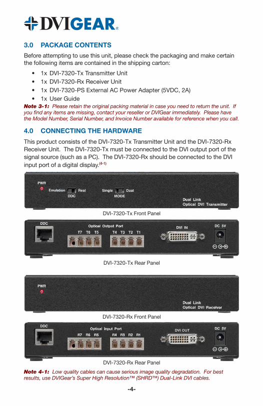
This product consists of the DVI-7320-Tx Transmitter Unit and the DVI-7320-Rx Receiver Unit. The DVI-7320-Tx must be connected to the DVI output port of the signal source (such as a PC). The DVI-7320-Rx should be connected to the DVI input port of a digital display.(4-1)
DVI-7320-Tx Front Panel
DVI-7320-Tx Rear Panel
DVI-7320-Rx Front Panel
DVI-7320-Rx Rear Panel
Note 4-1: Low quality cables can cause serious image quality degradation. For best results, use DVIGear’s Super High Resolution™ (SHRD™) Dual-Link DVI cables.
-4-
-5-
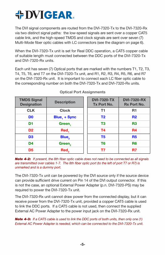
The DVI signal components are routed from the DVI-7320-Tx to the DVI-7320-Rx via two distinct signal paths: the low-speed signals are sent over a copper CAT5 cable link, and the high-speed TMDS and clock signals are sent over seven (7) Multi-Mode fiber optic cables with LC connectors (see the diagram on page 6).
When the DVI-7320-Tx unit is set for Real DDC operation, a CAT5 copper cable of suitable length must connected between the DDC ports of the DVI-7320-Tx and DVI-7320-Rx units.
Each unit has seven (7) Optical ports that are marked with the numbers T1, T2, T3, T4, T5, T6, and T7 on the DVI-7320-Tx unit, and R1, R2, R3, R4, R5, R6, and R7 on the DVI-7320-Rx unit. It is important to connect each LC fiber optic cable to the corresponding number on both the DVI-7320-Tx and DVI-7320-Rx units.
Optical Port Assignments
TMDS Signal Designation
DescriptionDVI-7320-TXTx Port No.
DVI-7320-RXRx Port No.
CLK Clock T1 R1
D0 Blue1 + Sync T2 R2
D1 Green1 T3 R3
D2 Red1 T4 R4
D3 Blue2 T5 R5
D4 Green2 T6 R6
D5 Red2 T7 R7
Note 4-2: If present, the 8th fiber optic cable does not need to be connected as all signals are transmitted over cables 1-7. The 8th fiber optic port (to the left of port T7 or R7) is unmarked and is a dummy port.
The DVI-7320-Tx unit can be powered by the DVI source only if the source device can provide sufficient drive current on Pin 14 of the DVI output connector. If this is not the case, an optional External Power Adapter (p.n. DVI-7320-PS) may be required to power the DVI-7320-Tx unit.
The DVI-7320-Rx unit cannot draw power from the connected display, but it can receive power from the DVI-7320-Tx unit, provided a copper CAT5 cable is used to link the DDC ports. If a CAT5 cable is not used, then connect the supplied External AC Power Adapter to the power input jack on the DVI-7320-Rx unit.
Note 4-3: If a CAT5 cable is used to link the DDC ports of both units, then only one (1) External AC Power Adapter is needed, which can be connected to the DVI-7320-Tx unit.
-6-
5.0 OPERATING THE UNIT
5.1 DDC Communications
In Real DDC Mode, the EDID of the connected display is presented to the DVI source device via the DDC link between the DVI-7320-Tx and DVI-7320-Rx units. Since DDC communications are based on I2C technology, the maximum cable length for the DDC link (CAT5 cable) is 100 meters (328 ft.) as this is the limit of I2C extenders.
In DDC Emulation Mode, the connected display’s EDID can be stored in an EDID memory device located in the DVI-7320-Tx unit. When the DVI source boots, up it reads the EDID information stored in the DVI-7320-Tx in the same way as if the display were connected directly to it. The DDC Emulation Mode eliminates the need for the copper DDC link; hence it allows much longer cable runs (up to 500 meters) to be used.
5.2 Programming the EDID Memory
1.) To program the EDID memory, remove all connections to the DVI-7320-Tx unit.
2.) Set the DDC switch on the DVI-7320-Tx to the Emulation position.
3.) Connect a DVI cable between the DVI-7320-Tx and the display.
4.) Connect the External AC Power Adapter to the DVI-7320-Tx.
5.) After a brief delay, the red PWR LED will flash rapidly for 1-2 seconds, then turn OFF for a moment and finally turn back ON.
The EDID has now been successfully stored in the DVI-7320-Tx.
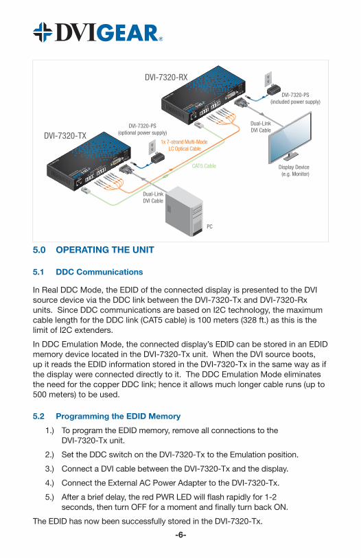
DVI-7320-RX
DVI-7320-TX
Dual-LinkDVI Cable
Display Device(e.g. Monitor)
Dual-LinkDVI Cable
PC
CAT5 Cable
1x 7-strand Multi-Mode LC Optical Cable
DVI-7320-PS(included power supply)
DVI-7320-PS(optional power supply)
-7-
5.3 Single and Dual Mode Operations
The DVI-7320 is capable of operating in either Single-Link or Dual-Link modes. The user may toggle between these modes using the switch on the front panel of the transmitter. In Dual Mode, the extender pair uses all 7x optical channels to transmit the video signal. In Single-Link Mode, only optical ports 1-4 are active, and the unit supports the maximum Single-Link resolutions listed on page 3.
6.0 TROUBLESHOOTING
If this unit does not appear to be functioning, confirm there is power to the transmitter and the receiver. The transmitter module must receive adequate power in order to function. In the event that the source device cannot provide sufficient power, the transmitter may be powered by an optional External AC Power Adapter. The receiver unit cannot draw power from the connected display, but it can receive power from the transmitter (see page 5).
If the system fails to display a signal, power OFF all devices and confirm that the following connections are properly installed: the Tx unit must be connected to the source using the shortest possible high quality cable. The Rx unit must be connected to the display using the shortest possible high quality cable. Each fiber optic cable must be connected between the corresponding ports (e.g. T1 to R1, T2 to R2, T3 to R3, etc.). If the unit is in Real EDID mode, then there must be a CAT5 cable connected between the DDC ports. If the unit is in Emulated EDID mode, then the EDID from the display must be stored in the Tx first before system setup (see page 6). Ensure that the fiber optic and CAT5 cables between the Tx and Rx are of the highest quality possible and within the supported lengths noted on page 3. Verify that the cables used do not show signs of damage and are not forced to bend beyond their minimum bend radius.
Check to ensure that the source signal resolution does not exceed those specified for Single-Link or Dual-Link modes on page 3. When using Dual-Link resolutions higher than those allowed by Single-Link mode, be certain to switch the unit into Dual Mode using the switch on the front panel of the transmitter.
Fiber optic ports and cables are very sensitive to dust, dirt and oil from handling. Even minute amounts can interfere or disrupt the optical transmission of the video signals. If erratic performance or disruption is noted, it may be necessary to have qualified technical personnel clean the optical ports and/or cable fibers using appropriate procedures and cleaning materials.
If the above has been verified and all necessary connections have been made, power the display device on first and then the signal source. If the system still fails to display an image, check to ensure that the signal source is compatible with the display by making a direct connection between the two so as to bypass the DVI-7320 extender pair. If there is still no image, then there is a compatibility issue between the source and the display that must be resolved.
If the problem persists after trying the above suggestions, please contact your dealer for additional assistance. If the dealer’s technical personnel are unable to assist you, please contact DVIGear via telephone at 1.888.463.9927 (toll-free for United States and Canada) or 1.770.421.6699. You may contact DVIGear by e-mail at [email protected].
7.0 LIMITED WARRANTY
LIMITED WARRANTY – Subject to the limitations stated below, DVIGear warrants that this product will be free from defects in materials and workmanship for a period of three (3) years from the date of purchase.
Should the product, in DVIGear’s opinion, prove defective within the warranty period stated above, DVIGear, at its option, will repair or replace this product without charge. Any defective parts replaced become the property of DVIGear. This warranty does not apply to products that have been damaged due to accident, unauthorized alterations, improper repair, modifications, inadequate maintenance and care, or use in any manner for which the product was not intended.
If repairs are necessary under this warranty policy, the original purchaser must obtain a Return Authorization Number from DVIGear and return the product freight prepaid to a location designated by DVIGear. After repairs are complete, the product will be returned, freight prepaid.
The foregoing warranty is the sole and exclusive warranty given by DVIGear, express or implied, and DVIGear disclaims all implied warranties, including but not limited to implied warranties of merchantability or fitness for a particular use.
LIMITATIONS – The liability of DVIGear with respect to any defective products will be limited to the repair or replacement of such products. In no event shall DVIGear be responsible or liable for any damage arising from the use of such defective products, including but not limited to loss of use, revenue or profit, whether such damages are direct, indirect, consequential or otherwise and whether such damages are incurred by the reseller, end-user, or any third-party.
8.0 REGULATORY COMPLIANCE
This product is compliant with appropriate FCC, CE and RoHS rules and regulations. The supplied AC Power Adapter is compliant with FCC, CE, UL, C-UL, CEC, GS, PSE and RoHS rules and regulations.
-8-

www.dvigear.com
Your Digital Connectivity Experts
Toll Free 888.463.9927Phone 770.421.6699Fax 770.234.4207
DVIGear, Inc.1059 Triad Court, Suite 8Marietta, Georgia 30062-2258
DVI-7320-UG-04 / March.2018