Embed Size (px)
Citation preview
DVR User Manual
For H.264 4/8/16-channel digital video recorder All rights reserved
Digital Video Recorder User Manual
CAUTION
Please read this user manual carefully to ensure that you can use the device correctly and safely We do not warrant all the content is correct. The contents of this manual are subject to change without notice This device should be operated only from the type of power source indicated on the marking label. The voltage of the power must be verified before using. Kindly remove the cables from the power source if the device is not to be used for a long period of time. Do not install this device near any heat sources such as radiators, heat registers, stoves or other device that produce heat Do not install this device near water. Clean only with a dry cloth Do not block any ventilation openings and ensure well ventilation around the machine Do not power off the DVR when the device is function. The correct procedure to shut down DVR is to stop recording firstly, and then use “shut down” button from the menu, and finally switching off the main power. This equipment is for indoor use only. Do not expose the machine in rain or moist environment. In case any solid or liquid get inside the machine’s case, please cut off the power supply immediately, and get it checked by a qualified technician. Refer all servicing to qualified service personnel. No any parts repaired by yourself without technical aid or approval. This manual is suitable for 4/8/16-channel digital video recorders. All examples and pictures used in the manual are from 16-channel DVR.
Digital Video Recorder User Manual
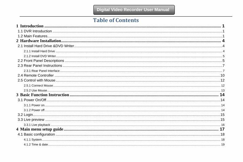
Table of Contents 1 Introduction ................................................................................................................................................... 1 1.1 DVR Introduction ..................................................................................................................................................................... 1 1.2 Main Features.......................................................................................................................................................................... 1
2 Hardware Installation ..................................................................................................................................... 4 2.1 Install Hard Drive &DVD Writer ................................................................................................................................................ 4
2.1.1 Install Hard Drive .................................................................................................................................................................................................. 4 2.1.2 Install DVD Writer.................................................................................................................................................................................................. 5
2.2 Front Panel Descriptions ......................................................................................................................................................... 5 2.3 Rear Panel Instructions ........................................................................................................................................................... 7
2.3.1 Rear Panel Interface ............................................................................................................................................................................................. 7 2.4 Remote Controller ................................................................................................................................................................. 10 2.5 Control with Mouse ................................................................................................................................................................ 12
2.5.1 Connect Mouse ................................................................................................................................................................................................... 12 2.5.2 Use Mouse .......................................................................................................................................................................................................... 13
3 Basic Function Instruction ............................................................................................................................ 14 3.1 Power On/Off ......................................................................................................................................................................... 14
3.1.1 Power on ............................................................................................................................................................................................................. 14 3.1.2 Power off ............................................................................................................................................................................................................. 14
3.2 Login ...................................................................................................................................................................................... 15 3.3 Live preview .......................................................................................................................................................................... 15
3.3.1 Live playback ...................................................................................................................................................................................................... 16 4 Main menu setup guide ................................................................................................................................. 17 4.1 Basic configuration ................................................................................................................................................................ 18
4.1.1 System ................................................................................................................................................................................................................ 18 4.1.2 Time & date ......................................................................................................................................................................................................... 19
Digital Video Recorder User Manual
4.1.3 DST ..................................................................................................................................................................................................................... 20 4.2 Live configuration .................................................................................................................................................................. 20
4.2.1 Live ..................................................................................................................................................................................................................... 20 4.2.2 Main monitor ....................................................................................................................................................................................................... 21 4.2.3 Spot ..................................................................................................................................................................................................................... 22 4.2.4 Mask ................................................................................................................................................................................................................... 22
4.3 Record configuration ............................................................................................................................................................. 23 4.3.1 Enable ................................................................................................................................................................................................................. 23 4.3.2 Record stream .................................................................................................................................................................................................... 24 4.3.3 Time .................................................................................................................................................................................................................... 24 4.3.4 Stamp .................................................................................................................................................................................................................. 25 4.3.5 Recycle record .................................................................................................................................................................................................... 26 4.3.6 Snap ................................................................................................................................................................................................................... 26
4.4 Schedule configuration .......................................................................................................................................................... 26 4.4.1 Schedule ............................................................................................................................................................................................................. 26 4.4.2 Motion ................................................................................................................................................................................................................. 27 4.4.3 Sensor ................................................................................................................................................................................................................ 28
4.5 Alarm configuration ................................................................................................................................................................ 28 4.5.1 Sensor ................................................................................................................................................................................................................ 29 4.5.2 Motion ................................................................................................................................................................................................................. 30 4.5.3 Video loss ........................................................................................................................................................................................................... 32 4.5.4 Other alarm ......................................................................................................................................................................................................... 33 4.5.5 Alarm out ............................................................................................................................................................................................................. 34
4.6 Network configuration ............................................................................................................................................................ 34 4.6.1 Network ............................................................................................................................................................................................................... 34 4.6.2 Sub stream.......................................................................................................................................................................................................... 35 4.6.3 Email ................................................................................................................................................................................................................... 36
Digital Video Recorder User Manual
4.6.4 Other settings ...................................................................................................................................................................................................... 37 4.7 User management configuration............................................................................................................................................ 40 4.8 P.T.Z configuration ................................................................................................................................................................. 42 4.9 Advanced ............................................................................................................................................................................... 45
4.9.1 Reset .................................................................................................................................................................................................................. 45 4.9.2 Import/Export ...................................................................................................................................................................................................... 45 4.9.3 Block/Allow list .................................................................................................................................................................................................... 45
5 Record search & playback and backup ......................................................................................................... 46 5.1 Time search ........................................................................................................................................................................... 46 5.2 Event search.......................................................................................................................................................................... 47 5.3 File management ................................................................................................................................................................... 48 5.4 Image .................................................................................................................................................................................... 49 5.5 Backup .................................................................................................................................................................................. 49
6 Manage DVR ............................................................................................................................................... 50 6.1 Check system information ..................................................................................................................................................... 50
6.1.1 System information ............................................................................................................................................................................................. 50 6.1.2 Event information ................................................................................................................................................................................................ 50 6.1.3 Log information ................................................................................................................................................................................................... 50 6.1.4 Network information ............................................................................................................................................................................................ 50 6.1.5 Online information ............................................................................................................................................................................................... 50
6.2 Manual alarm ......................................................................................................................................................................... 50 6.3 Disk management .................................................................................................................................................................. 51 6.4 Upgrade ................................................................................................................................................................................. 51 6.5 Logoff .................................................................................................................................................................................... 51
7 Remote Surveillance ..................................................................................................................................... 52 7.1 IE Remote Surveillance ......................................................................................................................................................... 52
7.1.1 On LAN ............................................................................................................................................................................................................... 52
Digital Video Recorder User Manual
7.1.2 On WAN .............................................................................................................................................................................................................. 52 7.2 Remote Surveillance through Apple PC ................................................................................................................................ 54
7.2.1 On LAN ............................................................................................................................................................................................................... 55 7.2.2 On WAN .............................................................................................................................................................................................................. 57
7.3 The remote live preview interface .......................................................................................................................................... 58 7.4 Remote playback & backup ................................................................................................................................................... 61
7.4.1 Remote playback ................................................................................................................................................................................................ 61 7.4.2 Remote backup ................................................................................................................................................................................................... 67
7.5 Remote System configuration ............................................................................................................................................... 68 7.6 Remote Management ............................................................................................................................................................ 69
Remote Information Search ......................................................................................................................................................................................... 69 8 Mobile Surveillance ...................................................................................................................................... 70 8.1 By Phones with Windows mobile ........................................................................................................................................... 70 8.2 By Phones with Symbian ....................................................................................................................................................... 71 8.3 The Software installation for iPhone mobile clients ................................................................................................................ 73 8.4 The installation & operation methods for Android mobile clients ............................................................................................ 80 8.5 Installation and operation Methods for BlackBerry Mobile phone Client ................................................................................ 86
8.5.1 Installation instruction for BlackBerry Mobile phone Client .................................................................................................................................. 86 8.5.2 Operation method for Blackberry mobile phone client ........................................................................................................................................ 88
Appendix A FAQ…......................................................................................................................................................................92 Appendix B Calculate Recording Capacity..............................................................................................................................98 Appendix C Compatible Devices..............................................................................................................................................99 Appendix D 4-CH DVR Specifications.....................................................................................................................................101 Appendix E 8-CH DVR Specifications.....................................................................................................................................102 Appendix F 16-CH DVR Specifications....................................................................................................................................103
1
Digital Video Recorder User Manual
1 Introduction
1.1 DVR Introduction This model of DVR (Digital Video Recorder) is designed for high performance CCTV solutions. It adopts state of the art video processing chips and embedded Linux system. Meanwhile, it utilizes most advanced technologies, such as standard H.264 with low bit rate, Dual stream, SATA interface, VGA output mouse supported, IE browser supported with full remote control, mobile view(by phones), etc., ensuring powerful functions and high stability. Due to these distinctive characteristics, it is widely used in banks, telecommunication, transportation, factories, warehouse, and other related applications.
1.2 Main Features
COMPRESSION FORMAT • Standard H.264 compression with low bit rate and better image quality
LIVE SURVEILLANCE • Support HD VGA output • Support channel security by hiding live display • Display the local record state and basic information • Support USB to make full control
RECORD MEDIA • Support two SATA HDD to record for a longer time without any limitation
BACKUP • Support USB 2.0 devices to backup • Support built-in SATA DVD writer to backup • Support saving recorded files with AVI standard format to a remote computer through internet
2
Digital Video Recorder User Manual
RECORD & PLAYBACK • Record modes: Manual, Schedule, Motion detection and Sensor alarm recording • Support recycle after HDD full • Resolution, frame rate and picture quality are adjustable • 128MB for every video file packaging • 4 audio channels available • Three record search mode: time search, event search and image search • Support 1/4 screen playback simultaneously • Support deleting and locking the recorded files one by one • Support remote playback in Network Client through LAN or internet
ALARM • 1 channel alarm output and 4/8/16 channel alarm input available • Support schedule for motion detection and sensor alarm • Support pre-recording and post recording • Support linked channels recording once motion or alarm triggered on certain channel • Support linked PTZ preset ,auto cruise and track of the corresponding channel
PTZ CONTROL • Support various PTZ protocols • Support 128 PTZ presets and 8 auto cruise tracks • Support remote PTZ control through internet
SECURITY • Customize user right: log search, system setup, two way audio, file management, disk management, remote login, live view, manual record, playback, PTZ control and remote live view
3
Digital Video Recorder User Manual
• Support 1 administrator and 63 users. • Support event log recording and checking, events unlimited
NETWORK • Support TCP/IP, DHCP, PPPoE, DDNS protocol • Support IE browser to do remote view • Support setup client connection amount • Support dual stream. Network stream is adjustable independently to fit the network bandwidth and environment. • Support picture snap and color adjustment in remote live • Support remote time and event search, and channel playback with picture snap • Support remote PTZ control with preset and auto cruise • Support remote full menu setup, changing all the DVR parameters remotely • Support mobile surveillance by smart phones , symbian, WinCE, Iphone or Gphone, blackberry, 3G network available • Support CMS to manage multi devices on internet
4
Digital Video Recorder User Manual
2 Hardware Installation Notice: Check the unit and the accessories after getting the DVR.
Please disconnect the power before being connected to other devices. Don't hot plug in/out
2.1 Install Hard Drive &DVD Writer 2.1.1 Install Hard Drive
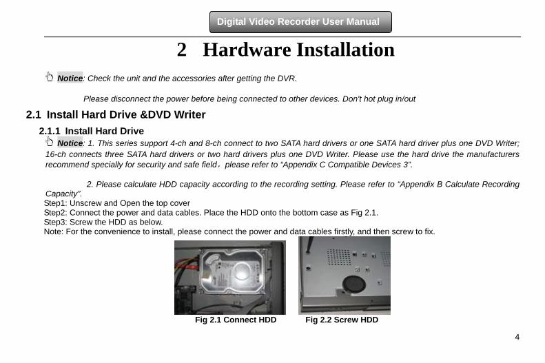
Notice: 1. This series support 4-ch and 8-ch connect to two SATA hard drivers or one SATA hard driver plus one DVD Writer; 16-ch connects three SATA hard drivers or two hard drivers plus one DVD Writer. Please use the hard drive the manufacturers recommend specially for security and safe field,please refer to “Appendix C Compatible Devices 3”. 2. Please calculate HDD capacity according to the recording setting. Please refer to “Appendix B Calculate Recording Capacity”. Step1: Unscrew and Open the top cover Step2: Connect the power and data cables. Place the HDD onto the bottom case as Fig 2.1. Step3: Screw the HDD as below. Note: For the convenience to install, please connect the power and data cables firstly, and then screw to fix.
Fig 2.1 Connect HDD Fig 2.2 Screw HDD
5
Digital Video Recorder User Manual
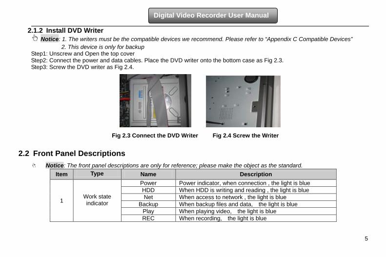
2.1.2 Install DVD Writer Notice: 1. The writers must be the compatible devices we recommend. Please refer to “Appendix C Compatible Devices”
2. This device is only for backup Step1: Unscrew and Open the top cover Step2: Connect the power and data cables. Place the DVD writer onto the bottom case as Fig 2.3. Step3: Screw the DVD writer as Fig 2.4.
Fig 2.3 Connect the DVD Writer Fig 2.4 Screw the Writer
2.2 Front Panel Descriptions Notice: The front panel descriptions are only for reference; please make the object as the standard.
Item Type Name Description
1
Work state indicator
Power Power indicator, when connection , the light is blue HDD When HDD is writing and reading , the light is blue Net When access to network , the light is blue
Backup When backup files and data, the light is blue Play When playing video, the light is blue REC When recording, the light is blue
6
Digital Video Recorder User Manual
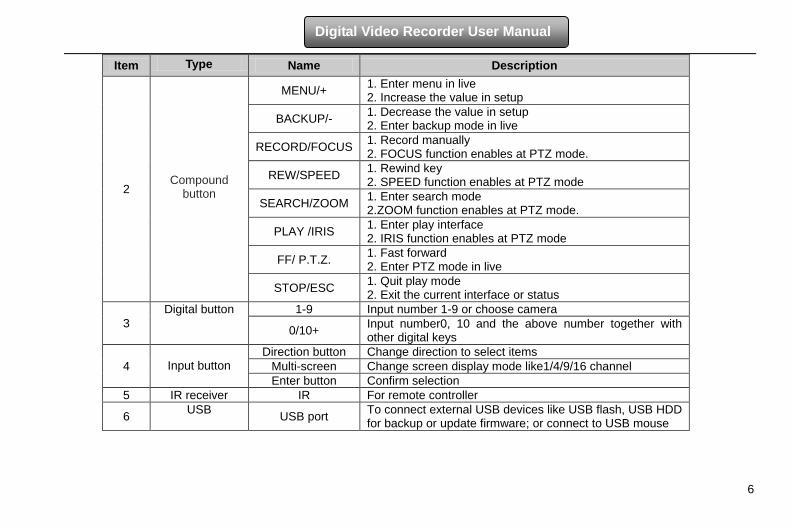
Item Type Name Description
2
Compound button
MENU/+ 1. Enter menu in live 2. Increase the value in setup
BACKUP/- 1. Decrease the value in setup 2. Enter backup mode in live
RECORD/FOCUS 1. Record manually 2. FOCUS function enables at PTZ mode.
REW/SPEED 1. Rewind key 2. SPEED function enables at PTZ mode
SEARCH/ZOOM 1. Enter search mode 2.ZOOM function enables at PTZ mode.
PLAY /IRIS 1. Enter play interface 2. IRIS function enables at PTZ mode
FF/ P.T.Z. 1. Fast forward 2. Enter PTZ mode in live
STOP/ESC 1. Quit play mode 2. Exit the current interface or status
3 Digital button 1-9 Input number 1-9 or choose camera
0/10+ Input number0, 10 and the above number together with other digital keys
4
Input button Direction button Change direction to select items
Multi-screen Change screen display mode like1/4/9/16 channel Enter button Confirm selection
5 IR receiver IR For remote controller
6 USB USB port To connect external USB devices like USB flash, USB HDD for backup or update firmware; or connect to USB mouse
7
Digital Video Recorder User Manual
2.3 Rear Panel Instructions 2.3.1 Rear Panel Interface
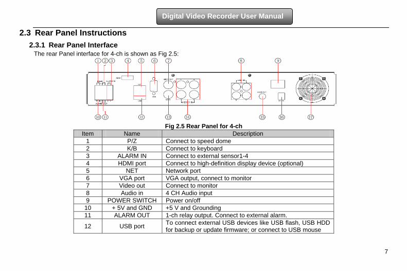
The rear Panel interface for 4-ch is shown as Fig 2.5:
Fig 2.5 Rear Panel for 4-ch
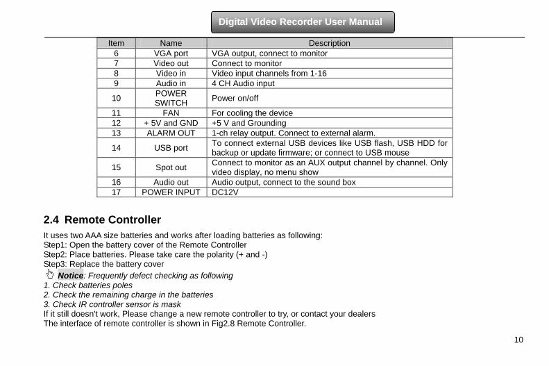
Item Name Description 1 P/Z Connect to speed dome 2 K/B Connect to keyboard 3 ALARM IN Connect to external sensor1-4 4 HDMI port Connect to high-definition display device (optional) 5 NET Network port 6 VGA port VGA output, connect to monitor 7 Video out Connect to monitor 8 Audio in 4 CH Audio input 9 POWER SWITCH Power on/off
10 + 5V and GND +5 V and Grounding 11 ALARM OUT 1-ch relay output. Connect to external alarm.
12 USB port To connect external USB devices like USB flash, USB HDD for backup or update firmware; or connect to USB mouse
8
Digital Video Recorder User Manual
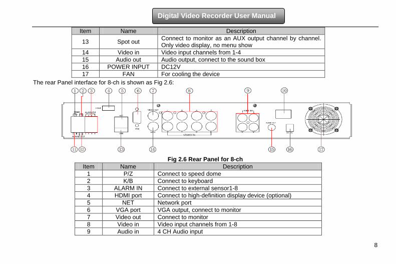
Item Name Description
13 Spot out Connect to monitor as an AUX output channel by channel. Only video display, no menu show
14 Video in Video input channels from 1-4 15 Audio out Audio output, connect to the sound box 16 POWER INPUT DC12V 17 FAN For cooling the device
The rear Panel interface for 8-ch is shown as Fig 2.6:
Fig 2.6 Rear Panel for 8-ch
Item Name Description 1 P/Z Connect to speed dome 2 K/B Connect to keyboard 3 ALARM IN Connect to external sensor1-8 4 HDMI port Connect to high-definition display device (optional) 5 NET Network port 6 VGA port VGA output, connect to monitor 7 Video out Connect to monitor 8 Video in Video input channels from 1-8 9 Audio in 4 CH Audio input
9
Digital Video Recorder User Manual
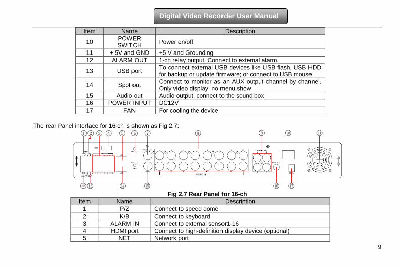
Item Name Description
10 POWER SWITCH Power on/off
11 + 5V and GND +5 V and Grounding 12 ALARM OUT 1-ch relay output. Connect to external alarm.
13 USB port To connect external USB devices like USB flash, USB HDD for backup or update firmware; or connect to USB mouse
14 Spot out Connect to monitor as an AUX output channel by channel. Only video display, no menu show
15 Audio out Audio output, connect to the sound box 16 POWER INPUT DC12V 17 FAN For cooling the device
The rear Panel interface for 16-ch is shown as Fig 2.7:
Fig 2.7 Rear Panel for 16-ch
Item Name Description 1 P/Z Connect to speed dome 2 K/B Connect to keyboard 3 ALARM IN Connect to external sensor1-16 4 HDMI port Connect to high-definition display device (optional) 5 NET Network port
10
Digital Video Recorder User Manual
Item Name Description 6 VGA port VGA output, connect to monitor 7 Video out Connect to monitor 8 Video in Video input channels from 1-16 9 Audio in 4 CH Audio input
10 POWER SWITCH Power on/off
11 FAN For cooling the device 12 + 5V and GND +5 V and Grounding 13 ALARM OUT 1-ch relay output. Connect to external alarm.
14 USB port To connect external USB devices like USB flash, USB HDD for backup or update firmware; or connect to USB mouse
15 Spot out Connect to monitor as an AUX output channel by channel. Only video display, no menu show
16 Audio out Audio output, connect to the sound box 17 POWER INPUT DC12V
2.4 Remote Controller It uses two AAA size batteries and works after loading batteries as following: Step1: Open the battery cover of the Remote Controller Step2: Place batteries. Please take care the polarity (+ and -) Step3: Replace the battery cover
Notice: Frequently defect checking as following 1. Check batteries poles 2. Check the remaining charge in the batteries 3. Check IR controller sensor is mask If it still doesn't work, Please change a new remote controller to try, or contact your dealers The interface of remote controller is shown in Fig2.8 Remote Controller.
11
Digital Video Recorder User Manual
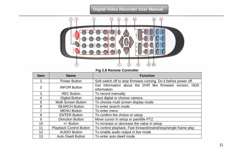
Fig 2.8 Remote Controller
Item Name Function 1 Power Button Soft switch off to stop firmware running. Do it before power off.
2 INFOR Button Get information about the DVR like firmware version, HDD information
3 REC Button To record manually 4 Digital Button Input digital or choose camera 5 Multi Screen Button To choose multi screen display mode 6 SEARCH Button To enter search mode 7 MENU Button To enter menu 8 ENTER Button To confirm the choice or setup 9 Direction Button Move cursor in setup or pan/title PTZ
10 +/- Button To increase or decrease the value in setup 11 Playback Control Button To control playback, Fast forward/rewind/stop/single frame play 12 AUDIO Button To enable audio output in live mode 13 Auto Dwell Button To enter auto dwell mode
12
Digital Video Recorder User Manual
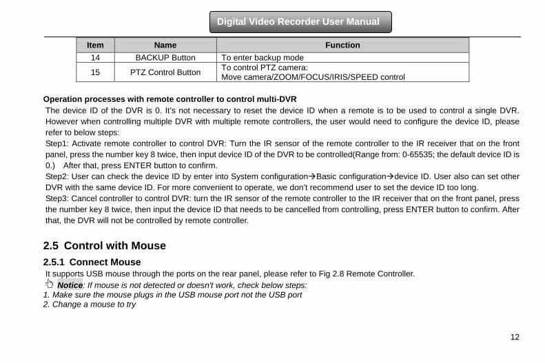
Item Name Function 14 BACKUP Button To enter backup mode
15 PTZ Control Button To control PTZ camera: Move camera/ZOOM/FOCUS/IRIS/SPEED control
Operation processes with remote controller to control multi-DVR The device ID of the DVR is 0. It’s not necessary to reset the device ID when a remote is to be used to control a single DVR. However when controlling multiple DVR with multiple remote controllers, the user would need to configure the device ID, please refer to below steps: Step1: Activate remote controller to control DVR: Turn the IR sensor of the remote controller to the IR receiver that on the front panel, press the number key 8 twice, then input device ID of the DVR to be controlled(Range from: 0-65535; the default device ID is 0.) After that, press ENTER button to confirm. Step2: User can check the device ID by enter into System configurationBasic configurationdevice ID. User also can set other DVR with the same device ID. For more convenient to operate, we don’t recommend user to set the device ID too long. Step3: Cancel controller to control DVR: turn the IR sensor of the remote controller to the IR receiver that on the front panel, press the number key 8 twice, then input the device ID that needs to be cancelled from controlling, press ENTER button to confirm. After that, the DVR will not be controlled by remote controller.
2.5 Control with Mouse 2.5.1 Connect Mouse It supports USB mouse through the ports on the rear panel, please refer to Fig 2.8 Remote Controller.
Notice: If mouse is not detected or doesn't work, check below steps: 1. Make sure the mouse plugs in the USB mouse port not the USB port 2. Change a mouse to try
13
Digital Video Recorder User Manual
2.5.2 Use Mouse In live: Double-click left button on one camera to be full screen display. Double-click again to return to the previous screen display. Click right button to show the control bar at the bottom of the screen as Fig 2.8 Remote Controller. Here are all control and setup.
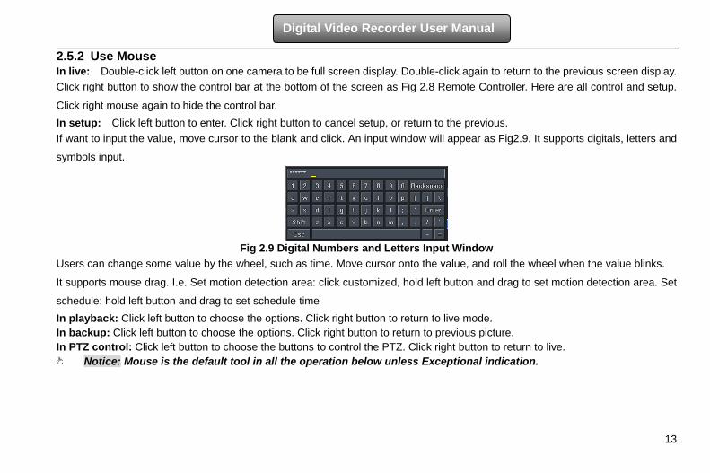
Click right mouse again to hide the control bar. In setup: Click left button to enter. Click right button to cancel setup, or return to the previous. If want to input the value, move cursor to the blank and click. An input window will appear as Fig2.9. It supports digitals, letters and
symbols input.
Fig 2.9 Digital Numbers and Letters Input Window
Users can change some value by the wheel, such as time. Move cursor onto the value, and roll the wheel when the value blinks.
It supports mouse drag. I.e. Set motion detection area: click customized, hold left button and drag to set motion detection area. Set
schedule: hold left button and drag to set schedule time In playback: Click left button to choose the options. Click right button to return to live mode. In backup: Click left button to choose the options. Click right button to return to previous picture. In PTZ control: Click left button to choose the buttons to control the PTZ. Click right button to return to live.
Notice: Mouse is the default tool in all the operation below unless Exceptional indication.
14
Digital Video Recorder User Manual
3 Basic Function Instruction 3.1 Power On/Off
Before you power on the unit, please make sure all the connection is good.
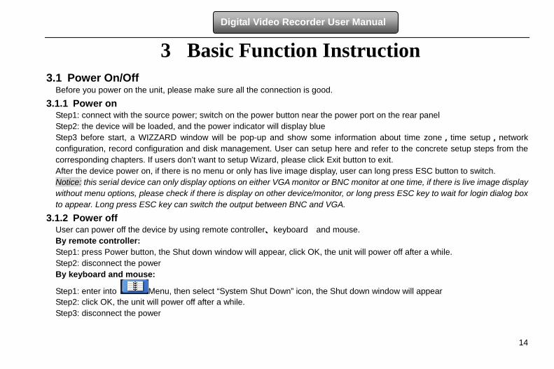
3.1.1 Power on Step1: connect with the source power; switch on the power button near the power port on the rear panel Step2: the device will be loaded, and the power indicator will display blue Step3 before start, a WIZZARD window will be pop-up and show some information about time zone,time setup,network configuration, record configuration and disk management. User can setup here and refer to the concrete setup steps from the corresponding chapters. If users don’t want to setup Wizard, please click Exit button to exit. After the device power on, if there is no menu or only has live image display, user can long press ESC button to switch. Notice: this serial device can only display options on either VGA monitor or BNC monitor at one time, if there is live image display without menu options, please check if there is display on other device/monitor, or long press ESC key to wait for login dialog box to appear. Long press ESC key can switch the output between BNC and VGA.
3.1.2 Power off User can power off the device by using remote controller、keyboard and mouse. By remote controller: Step1: press Power button, the Shut down window will appear, click OK, the unit will power off after a while. Step2: disconnect the power By keyboard and mouse:
Step1: enter into Menu, then select “System Shut Down” icon, the Shut down window will appear Step2: click OK, the unit will power off after a while. Step3: disconnect the power
15
Digital Video Recorder User Manual
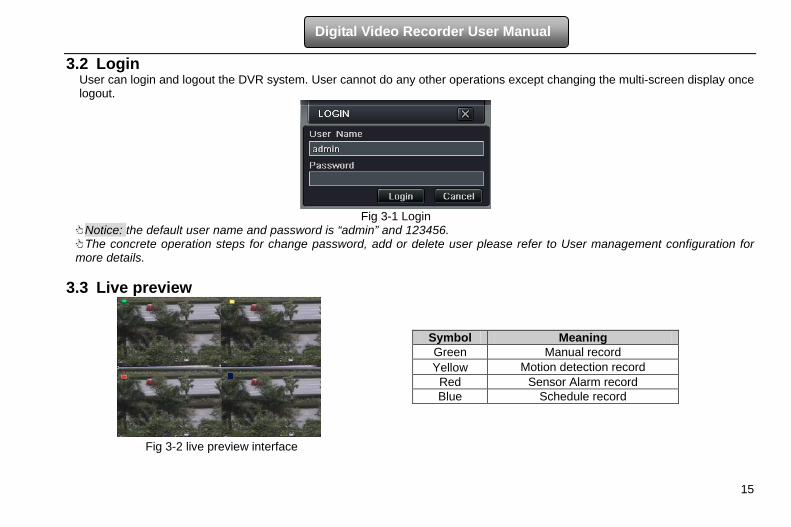
3.2 Login User can login and logout the DVR system. User cannot do any other operations except changing the multi-screen display once logout.
Fig 3-1 Login
Notice: the default user name and password is “admin” and 123456. The concrete operation steps for change password, add or delete user please refer to User management configuration for
more details.
3.3 Live preview
Fig 3-2 live preview interface
Symbol Meaning Green Manual record Yellow Motion detection record
Red Sensor Alarm record Blue Schedule record
16
Digital Video Recorder User Manual
3.3.1 Live playback
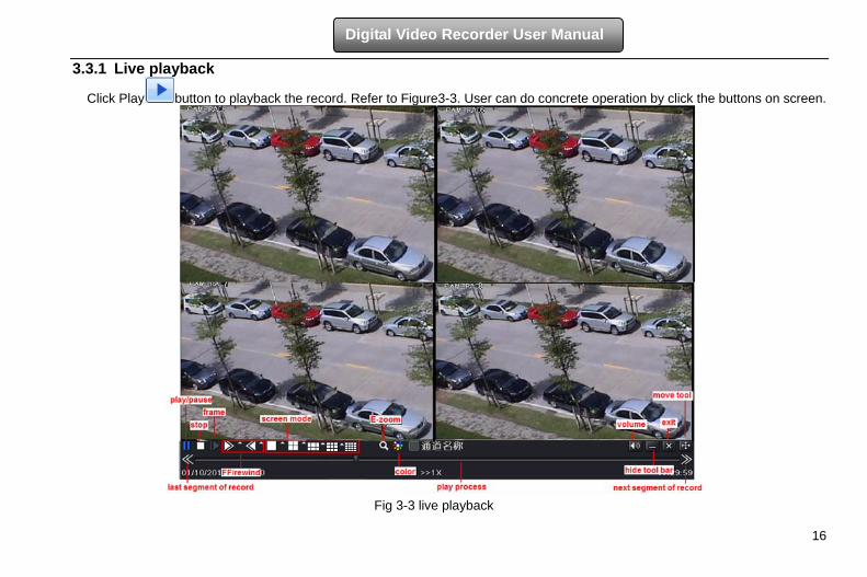
Click Play button to playback the record. Refer to Figure3-3. User can do concrete operation by click the buttons on screen.
Fig 3-3 live playback
17
Digital Video Recorder User Manual
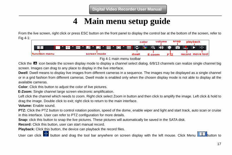
4 Main menu setup guide From the live screen, right click or press ESC button on the front panel to display the control bar at the bottom of the screen, refer to Fig 4-1:
Fig 4-1 main menu toolbar
Click the icon beside the screen display mode to display a channel select dialog. 6/8/13 channels can realize single channel big screen. Images can drag to any place to display in the live interface. Dwell: Dwell means to display live images from different cameras in a sequence. The images may be displayed as a single channel or in a grid fashion from different cameras. Dwell mode is enabled only when the chosen display mode is not able to display all the available cameras. Color: Click this button to adjust the color of live pictures. E-Zoom: Single channel large screen electronic amplification. Left click the channel which needs to zoom. Right click select Zoom in button and then click to amplify the image. Left click & hold to drag the image. Double click to exit; right click to return to the main interface. Volume: Enable sound. PTZ: Click the PTZ button to control rotation position, speed of the dome, enable wiper and light and start track, auto scan or cruise in this interface. User can refer to PTZ configuration for more details. Snap: click this button to snap the live pictures. These pictures will automatically be saved in the SATA disk. Record: Click this button, user can start manual record. Playback: Click this button, the device can playback the record files.
User can click button and drag the tool bar anywhere on screen display with the left mouse. Click Menu button to
18
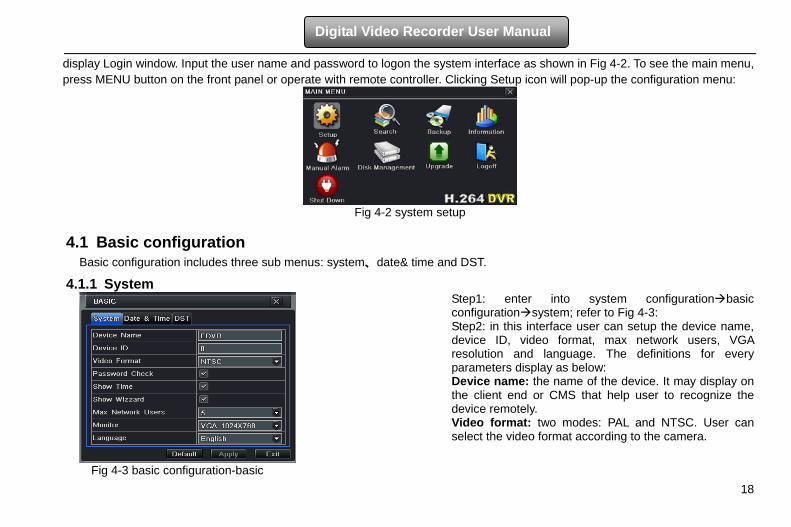
Digital Video Recorder User Manual
display Login window. Input the user name and password to logon the system interface as shown in Fig 4-2. To see the main menu, press MENU button on the front panel or operate with remote controller. Clicking Setup icon will pop-up the configuration menu:
Fig 4-2 system setup
4.1 Basic configuration
Basic configuration includes three sub menus: system、date& time and DST.
4.1.1 System
Step1: enter into system configurationbasic configurationsystem; refer to Fig 4-3: Step2: in this interface user can setup the device name, device ID, video format, max network users, VGA resolution and language. The definitions for every parameters display as below: Device name: the name of the device. It may display on the client end or CMS that help user to recognize the device remotely. Video format: two modes: PAL and NTSC. User can select the video format according to the camera.
Fig 4-3 basic configuration-basic
19
Digital Video Recorder User Manual
Password check: If enabled, the user would need to input the user name and the password for performing corresponding operations. Show time: display time in live. Show wizard: if this item is selected, there will display an opening wizard with time zone and time setup information Max network uses: set the max user amount of network connection VGA resolution: the resolution of live display interface, range from: VGA800*600, VGA1024*768, VGA1280*1024 and CVBS Note:When switch between VGA and CVBS will change the menu output mode, please connect to relevant monitor. Language: setup the menu language. Note: After changed the language and video output, the device needs to login again.
4.1.2 Time & date
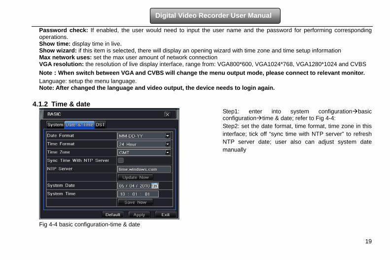
Step1: enter into system configurationbasic configurationtime & date; refer to Fig 4-4: Step2: set the date format, time format, time zone in this interface; tick off “sync time with NTP server” to refresh NTP server date; user also can adjust system date manually
Fig 4-4 basic configuration-time & date
20
Digital Video Recorder User Manual
4.1.3 DST
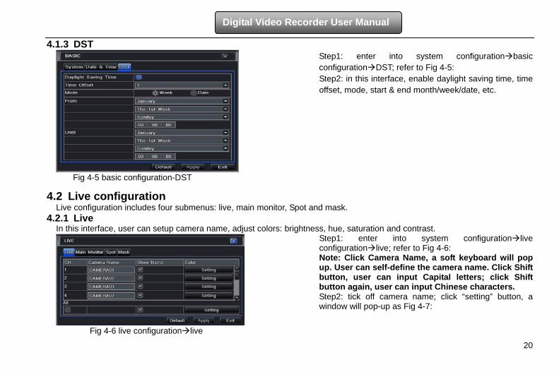
Step1: enter into system configurationbasic configurationDST; refer to Fig 4-5: Step2: in this interface, enable daylight saving time, time offset, mode, start & end month/week/date, etc.
Fig 4-5 basic configuration-DST
4.2 Live configuration Live configuration includes four submenus: live, main monitor, Spot and mask.
4.2.1 Live In this interface, user can setup camera name, adjust colors: brightness, hue, saturation and contrast.
Step1: enter into system configurationlive configurationlive; refer to Fig 4-6: Note: Click Camera Name, a soft keyboard will pop up. User can self-define the camera name. Click Shift button, user can input Capital letters; click Shift button again, user can input Chinese characters. Step2: tick off camera name; click “setting” button, a window will pop-up as Fig 4-7:
Fig 4-6 live configurationlive
21
Digital Video Recorder User Manual
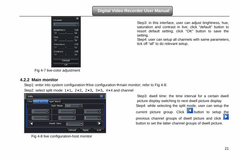
Step3: in this interface, user can adjust brightness, hue, saturation and contrast in live; click “default” button to resort default setting; click “OK” button to save the setting. Step4: user can setup all channels with same parameters, tick off “all” to do relevant setup.
Fig 4-7 live-color adjustment
4.2.2 Main monitor Step1: enter into system configurationlive configurationmain monitor; refer to Fig 4-8: Step2: select split mode: 1×1、2×2、2×3、3×3、4×4 and channel
Step3: dwell time: the time interval for a certain dwell picture display switching to next dwell picture display
Step4: while selecting the split mode, user can setup the
current picture group. Click button to setup the
previous channel groups of dwell picture and click button to set the latter channel groups of dwell picture.
Fig 4-8 live configuration-host monitor

22
Digital Video Recorder User Manual
4.2.3 Spot Step1: enter into system configurationlive configurationSpot; refer to Fig 4-9: Step2: select split mode: 1×1and channel.
Step 3: dwell time: the time interval for a certain dwell picture display switching to next dwell picture display
Step 4: while selecting the split mode, user can setup the
current picture group. Click button to setup the
previous channel groups of dwell picture, click button to set the latter channel groups of dwell picture.
Fig 4-9 live configuration-Spot
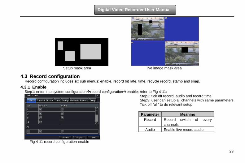
4.2.4 Mask User can setup private mask area on the live image picture, max threes areas.
Setup mask area: click Setting button and then enter into live image. Next, press left mouse and drag mouse to set mask area referring to the left picture. Click Apply button to save the setting. Delete mask area: select a certain mask area and left click to delete that mask area. Then click Apply button to save the setting.
Fig 4-10 live configuration-mask
23
Digital Video Recorder User Manual
Setup mask area live image mask area
4.3 Record configuration Record configuration includes six sub menus: enable, record bit rate, time, recycle record, stamp and snap.
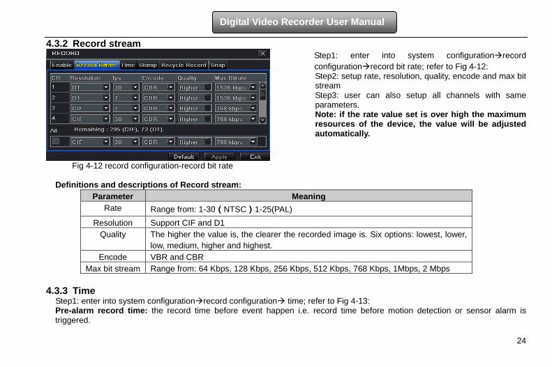
4.3.1 Enable Step1: enter into system configurationrecord configurationenable; refer to Fig 4-11:
Step2: tick off record, audio and record time Step3: user can setup all channels with same parameters. Tick off “all” to do relevant setup.
Fig 4-11 record configuration-enable
Parameter Meaning Record Record switch of every
channels Audio Enable live record audio
24
Digital Video Recorder User Manual
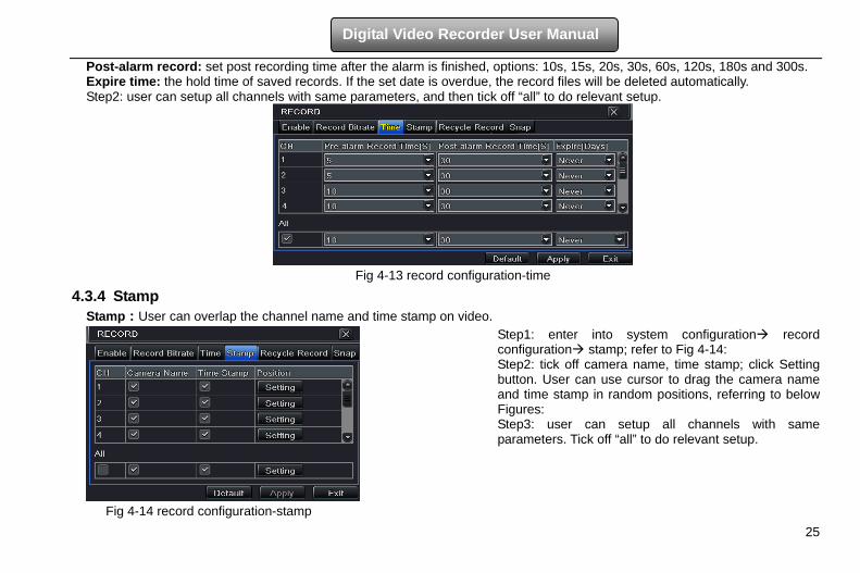
4.3.2 Record stream Step1: enter into system configurationrecord configurationrecord bit rate; refer to Fig 4-12: Step2: setup rate, resolution, quality, encode and max bit stream Step3: user can also setup all channels with same parameters. Note: if the rate value set is over high the maximum resources of the device, the value will be adjusted automatically.
Fig 4-12 record configuration-record bit rate Definitions and descriptions of Record stream:
Parameter Meaning Rate Range from: 1-30(NTSC)1-25(PAL)
Resolution Support CIF and D1 Quality The higher the value is, the clearer the recorded image is. Six options: lowest, lower,
low, medium, higher and highest. Encode VBR and CBR
Max bit stream Range from: 64 Kbps, 128 Kbps, 256 Kbps, 512 Kbps, 768 Kbps, 1Mbps, 2 Mbps
4.3.3 Time Step1: enter into system configurationrecord configuration time; refer to Fig 4-13: Pre-alarm record time: the record time before event happen i.e. record time before motion detection or sensor alarm is triggered.
25
Digital Video Recorder User Manual
Post-alarm record: set post recording time after the alarm is finished, options: 10s, 15s, 20s, 30s, 60s, 120s, 180s and 300s. Expire time: the hold time of saved records. If the set date is overdue, the record files will be deleted automatically. Step2: user can setup all channels with same parameters, and then tick off “all” to do relevant setup.
Fig 4-13 record configuration-time
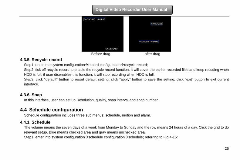
4.3.4 Stamp Stamp:User can overlap the channel name and time stamp on video.
Step1: enter into system configuration record configuration stamp; refer to Fig 4-14: Step2: tick off camera name, time stamp; click Setting button. User can use cursor to drag the camera name and time stamp in random positions, referring to below Figures: Step3: user can setup all channels with same parameters. Tick off “all” to do relevant setup.
Fig 4-14 record configuration-stamp
26
Digital Video Recorder User Manual
Before drag after drag
4.3.5 Recycle record Step1: enter into system configurationrecord configurationrecycle record; Step2: tick off recycle record to enable the recycle record function. It will cover the earlier recorded files and keep recoding when HDD is full; if user disenables this function, it will stop recording when HDD is full. Step3: click “default” button to resort default setting; click “apply” button to save the setting; click “exit” button to exit current interface.
4.3.6 Snap In this interface, user can set up Resolution, quality, snap interval and snap number.
4.4 Schedule configuration Schedule configuration includes three sub menus: schedule, motion and alarm.
4.4.1 Schedule The volume means the seven days of a week from Monday to Sunday and the row means 24 hours of a day. Click the grid to do relevant setup. Blue means checked area and gray means unchecked area. Step1: enter into system configurationschedule configurationschedule; referring to Fig 4-15:
27
Digital Video Recorder User Manual
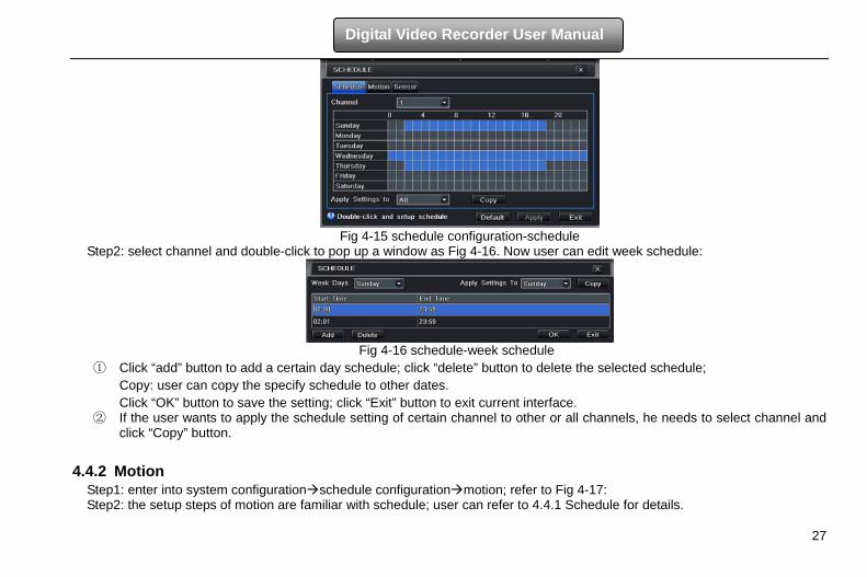
Fig 4-15 schedule configuration-schedule
Step2: select channel and double-click to pop up a window as Fig 4-16. Now user can edit week schedule:
Fig 4-16 schedule-week schedule
① Click “add” button to add a certain day schedule; click “delete” button to delete the selected schedule; Copy: user can copy the specify schedule to other dates. Click “OK” button to save the setting; click “Exit” button to exit current interface.
② If the user wants to apply the schedule setting of certain channel to other or all channels, he needs to select channel and click “Copy” button.
4.4.2 Motion
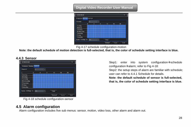
Step1: enter into system configurationschedule configurationmotion; refer to Fig 4-17: Step2: the setup steps of motion are familiar with schedule; user can refer to 4.4.1 Schedule for details.
28
Digital Video Recorder User Manual
Fig 4-17 schedule configuration-motion
Note: the default schedule of motion detection is full-selected, that is, the color of schedule setting interface is blue.
4.4.3 Sensor
Step1: enter into system configurationschedule configurationalarm; refer to Fig 4-18: Step2: the setup steps of alarm are familiar with schedule; user can refer to 4.4.1 Schedule for details. Note: the default schedule of sensor is full-selected, that is, the color of schedule setting interface is blue.
Fig 4-18 schedule configuration-sensor
4.5 Alarm configuration Alarm configuration includes five sub menus: sensor, motion, video loss, other alarm and alarm out.
29
Digital Video Recorder User Manual
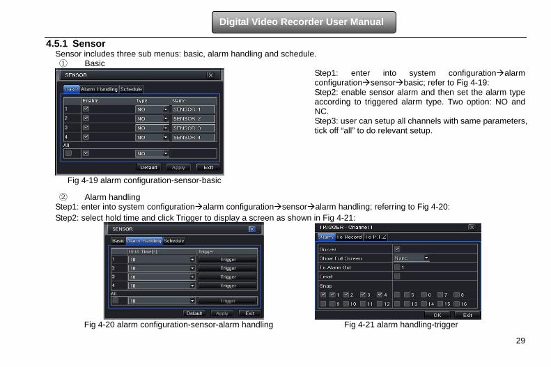
4.5.1 Sensor Sensor includes three sub menus: basic, alarm handling and schedule. ① Basic
Step1: enter into system configurationalarm configurationsensorbasic; refer to Fig 4-19: Step2: enable sensor alarm and then set the alarm type according to triggered alarm type. Two option: NO and NC. Step3: user can setup all channels with same parameters, tick off “all” to do relevant setup.
Fig 4-19 alarm configuration-sensor-basic
② Alarm handling Step1: enter into system configurationalarm configurationsensoralarm handling; referring to Fig 4-20: Step2: select hold time and click Trigger to display a screen as shown in Fig 4-21:
Fig 4-20 alarm configuration-sensor-alarm handling Fig 4-21 alarm handling-trigger
30
Digital Video Recorder User Manual
Step 3: If Buzzer is selected, there will be triggered buzzer alarm out. Full screen alarm: when alarm is triggered, there will pop up full screen alarm; Email: Select this function. When an alarm is triggered, a notification email will be sent to user’s designed email box including trigger events, time, snap pictures, device name, ID camera name etc. Snap: Select channels. When an alarm is trigged, the system will automatically save the captured pictures from the selected channel. If user ticks off Email function, these pictures will also be sent to user’s designed email box. To alarm out: After selecting the channel, there will be triggered alarm out in the designated channel. Click OK button to save the setting; click Exit button to exit the current interface. To record: Select recoding channels. It will record the camera when alarm is triggered. Click OK button to save the setting; click Exit button to exit the current interface. To P.T.Z: set linked preset and cruise for alarm. User can select any channel and multi channels as linked channels. Click OK button to save the setting; click Exit button to exit the current interface. Step4: user can setup all channels with same parameters. Tick off “all” to do relevant setup.
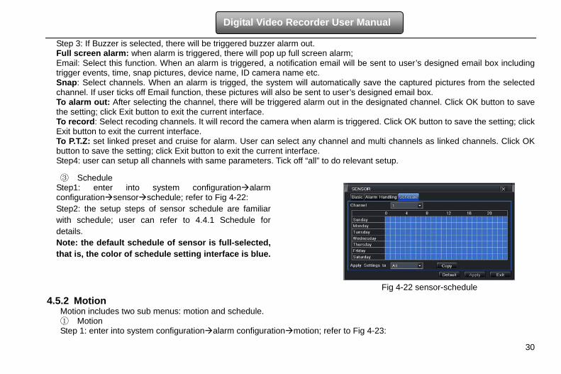
③ Schedule Step1: enter into system configurationalarm configurationsensorschedule; refer to Fig 4-22: Step2: the setup steps of sensor schedule are familiar with schedule; user can refer to 4.4.1 Schedule for details. Note: the default schedule of sensor is full-selected, that is, the color of schedule setting interface is blue.
Fig 4-22 sensor-schedule
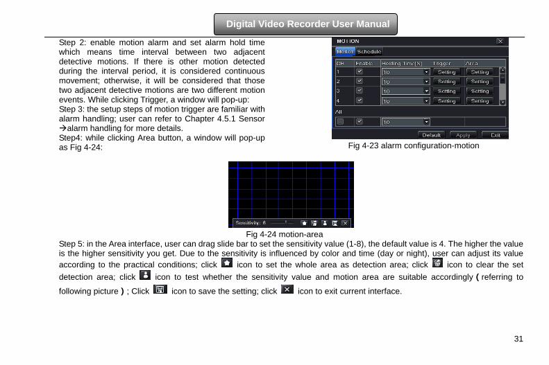
4.5.2 Motion Motion includes two sub menus: motion and schedule. ① Motion Step 1: enter into system configurationalarm configurationmotion; refer to Fig 4-23:
31
Digital Video Recorder User Manual
Step 2: enable motion alarm and set alarm hold time which means time interval between two adjacent detective motions. If there is other motion detected during the interval period, it is considered continuous movement; otherwise, it will be considered that those two adjacent detective motions are two different motion events. While clicking Trigger, a window will pop-up: Step 3: the setup steps of motion trigger are familiar with alarm handling; user can refer to Chapter 4.5.1 Sensor alarm handling for more details. Step4: while clicking Area button, a window will pop-up as Fig 4-24:
Fig 4-23 alarm configuration-motion
Fig 4-24 motion-area
Step 5: in the Area interface, user can drag slide bar to set the sensitivity value (1-8), the default value is 4. The higher the value is the higher sensitivity you get. Due to the sensitivity is influenced by color and time (day or night), user can adjust its value according to the practical conditions; click icon to set the whole area as detection area; click icon to clear the set detection area; click icon to test whether the sensitivity value and motion area are suitable accordingly(referring to
following picture); Click icon to save the setting; click icon to exit current interface.
32
Digital Video Recorder User Manual
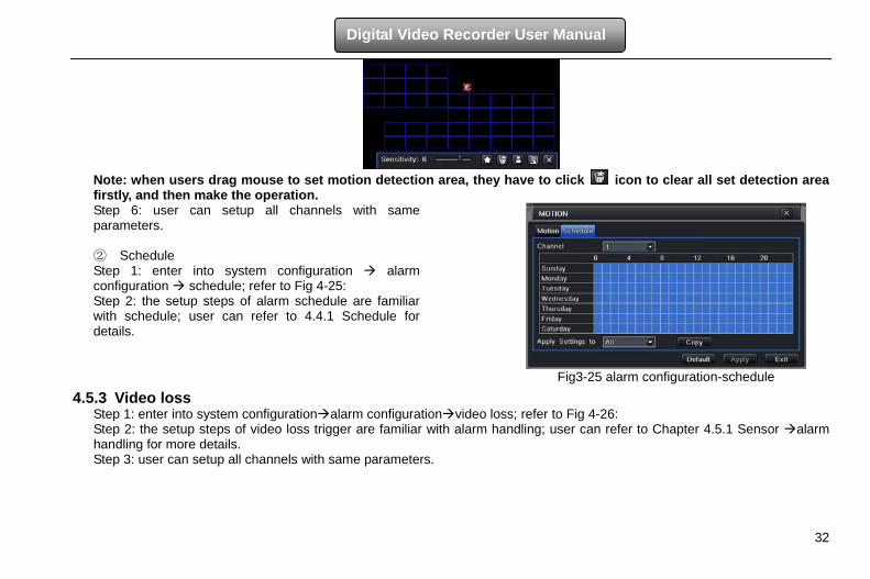
Note: when users drag mouse to set motion detection area, they have to click icon to clear all set detection area firstly, and then make the operation. Step 6: user can setup all channels with same parameters. ② Schedule Step 1: enter into system configuration alarm configuration schedule; refer to Fig 4-25: Step 2: the setup steps of alarm schedule are familiar with schedule; user can refer to 4.4.1 Schedule for details.
Fig3-25 alarm configuration-schedule
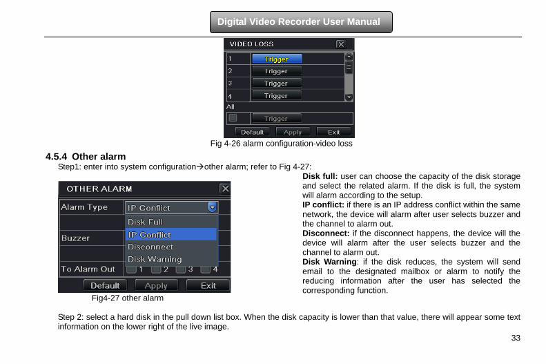
4.5.3 Video loss Step 1: enter into system configurationalarm configurationvideo loss; refer to Fig 4-26: Step 2: the setup steps of video loss trigger are familiar with alarm handling; user can refer to Chapter 4.5.1 Sensor alarm handling for more details. Step 3: user can setup all channels with same parameters.
33
Digital Video Recorder User Manual
Fig 4-26 alarm configuration-video loss
4.5.4 Other alarm Step1: enter into system configurationother alarm; refer to Fig 4-27:
Fig4-27 other alarm
Disk full: user can choose the capacity of the disk storage and select the related alarm. If the disk is full, the system will alarm according to the setup. IP conflict: if there is an IP address conflict within the same network, the device will alarm after user selects buzzer and the channel to alarm out. Disconnect: if the disconnect happens, the device will the device will alarm after the user selects buzzer and the channel to alarm out. Disk Warning: if the disk reduces, the system will send email to the designated mailbox or alarm to notify the reducing information after the user has selected the corresponding function.
Step 2: select a hard disk in the pull down list box. When the disk capacity is lower than that value, there will appear some text information on the lower right of the live image.
34
Digital Video Recorder User Manual
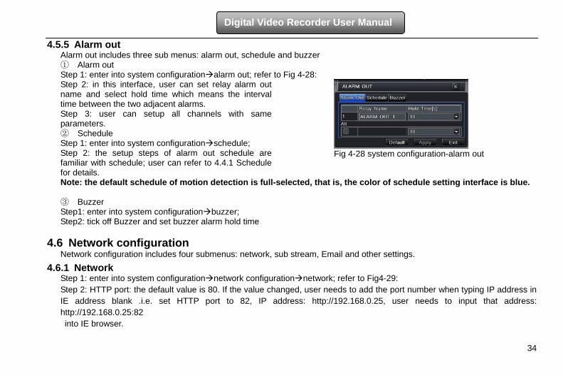
4.5.5 Alarm out Alarm out includes three sub menus: alarm out, schedule and buzzer ① Alarm out Step 1: enter into system configurationalarm out; refer to Fig 4-28: Step 2: in this interface, user can set relay alarm out name and select hold time which means the interval time between the two adjacent alarms. Step 3: user can setup all channels with same parameters. ② Schedule Step 1: enter into system configurationschedule; Step 2: the setup steps of alarm out schedule are familiar with schedule; user can refer to 4.4.1 Schedule for details.
Fig 4-28 system configuration-alarm out
Note: the default schedule of motion detection is full-selected, that is, the color of schedule setting interface is blue. ③ Buzzer Step1: enter into system configurationbuzzer; Step2: tick off Buzzer and set buzzer alarm hold time
4.6 Network configuration Network configuration includes four submenus: network, sub stream, Email and other settings.
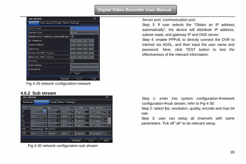
4.6.1 Network Step 1: enter into system configurationnetwork configurationnetwork; refer to Fig4-29: Step 2: HTTP port: the default value is 80. If the value changed, user needs to add the port number when typing IP address in IE address blank .i.e. set HTTP port to 82, IP address: http://192.168.0.25, user needs to input that address: http://192.168.0.25:82 into IE browser.
35
Digital Video Recorder User Manual
Server port: communication port. Step 3: If user selects the "Obtain an IP address automatically", the device will distribute IP address, subnet mask, and gateway IP and DNS server. Step 4: enable PPPoE to directly connect the DVR to internet via ADSL, and then input the user name and password. Next, click TEST button to test the effectiveness of the relevant information.
Fig 4-29 network configuration-network
4.6.2 Sub stream
Step 1: enter into system configurationnetwork configurationsub stream; refer to Fig 4-30: Step 2: select fps, resolution, quality, encode and max bit rate Step 3: user can setup all channels with same parameters. Tick off “all” to do relevant setup.
Fig 4-30 network configuration-sub stream
36
Digital Video Recorder User Manual
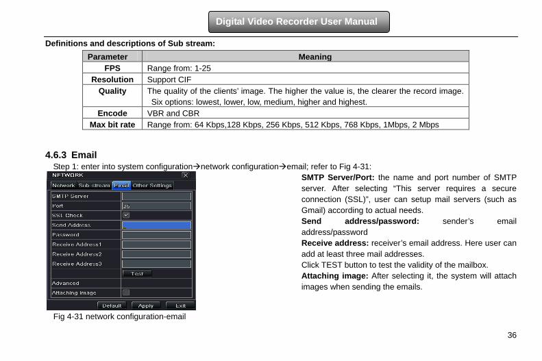
Definitions and descriptions of Sub stream: 4.6.3 Email
Step 1: enter into system configurationnetwork configurationemail; refer to Fig 4-31:
SMTP Server/Port: the name and port number of SMTP server. After selecting “This server requires a secure connection (SSL)”, user can setup mail servers (such as Gmail) according to actual needs. Send address/password: sender’s email address/password Receive address: receiver’s email address. Here user can add at least three mail addresses. Click TEST button to test the validity of the mailbox. Attaching image: After selecting it, the system will attach images when sending the emails.
Fig 4-31 network configuration-email
Parameter Meaning FPS Range from: 1-25
Resolution Support CIF Quality The quality of the clients’ image. The higher the value is, the clearer the record image.
Six options: lowest, lower, low, medium, higher and highest. Encode VBR and CBR
Max bit rate Range from: 64 Kbps,128 Kbps, 256 Kbps, 512 Kbps, 768 Kbps, 1Mbps, 2 Mbps
37
Digital Video Recorder User Manual
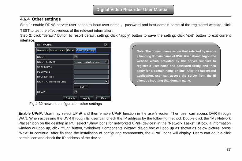
4.6.4 Other settings Step 1: enable DDNS server: user needs to input user name, password and host domain name of the registered website, click TEST to test the effectiveness of the relevant information. Step 2: click “default” button to resort default setting; click “apply” button to save the setting; click “exit” button to exit current interface.
Fig 4-32 network configuration-other settings
Enable UPnP: User may select UPnP and then enable UPnP function in the user’s router. Then user can access DVR through WAN. When accessing the DVR through IE, user can check the IP address by the following method: Double-click the “My Network Places” icon on the desktop in PC, select “Show icons for networked UPnP devices” in the “Network Tasks” list box, a information window will pop up, click “YES” button, “Windows Components Wizard” dialog box will pop up as shown as below picture, press “Next” to continue. After finished the installation of configuring components, the UPnP icons will display. Users can double-click certain icon and check the IP address of the device.
Note: The domain name server that selected by user is a banding domain name of DVR. User should logon the website which provided by the server supplier to register a user name and password firstly, and then apply for a domain name on line. After the successful application, user can access the server from the IE client by inputting that domain name.
38
Digital Video Recorder User Manual
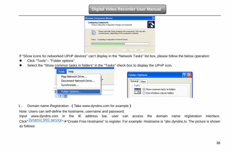
If “Show icons for networked UPnP devices” can’t display in the “Network Tasks” list box, please follow the below operation: Click “Tools”-- “Folder options” Select the “Show common tasks in folders” in the “Tasks” check box to display the UPnP icon.
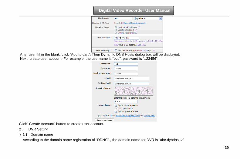
1. Domain name Registration (Take www.dyndns.com for example) Note: Users can self-define the hostname, username and password. Input www.dyndns.com in the IE address bar, user can access the domain name registration interface. Click” ””Create Free Hostname” to register. For example: Hostname is “abc.dyndns.tv. The picture is shown as follows:
39
Digital Video Recorder User Manual
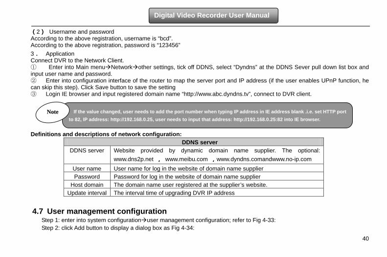
After user fill in the blank, click “Add to cart”. Then Dynamic DNS Hosts dialog box will be displayed. Next, create user account. For example, the username is “bcd”, password is “123456”.
Click” Create Account” button to create user account. 2. DVR Setting (1) Domain name
According to the domain name registration of “DDNS”,the domain name for DVR is “abc.dyndns.tv”
40
Digital Video Recorder User Manual
(2) Username and password According to the above registration, username is “bcd”. According to the above registration, password is “123456” 3. Application Connect DVR to the Network Client. ① Enter into Main menuNetworkother settings, tick off DDNS, select “Dyndns” at the DDNS Sever pull down list box and input user name and password. ② Enter into configuration interface of the router to map the server port and IP address (if the user enables UPnP function, he can skip this step). Click Save button to save the setting ③ Login IE browser and input registered domain name “http://www.abc.dyndns.tv”, connect to DVR client. Definitions and descriptions of network configuration:
DDNS server DDNS server Website provided by dynamic domain name supplier. The optional:
www.dns2p.net , www.meibu.com ,www.dyndns.comandwww.no-ip.com User name User name for log in the website of domain name supplier Password Password for log in the website of domain name supplier
Host domain The domain name user registered at the supplier’s website. Update interval The interval time of upgrading DVR IP address
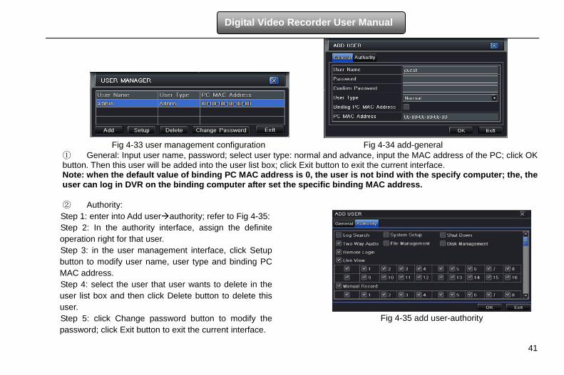
4.7 User management configuration Step 1: enter into system configurationuser management configuration; refer to Fig 4-33: Step 2: click Add button to display a dialog box as Fig 4-34:
If the value changed, user needs to add the port number when typing IP address in IE address blank .i.e. set HTTP port to 82, IP address: http://192.168.0.25, user needs to input that address: http://192.168.0.25:82 into IE browser.
NNoottee
41
Digital Video Recorder User Manual
Fig 4-33 user management configuration Fig 4-34 add-general
① General: Input user name, password; select user type: normal and advance, input the MAC address of the PC; click OK button. Then this user will be added into the user list box; click Exit button to exit the current interface. Note: when the default value of binding PC MAC address is 0, the user is not bind with the specify computer; the, the user can log in DVR on the binding computer after set the specific binding MAC address. ② Authority: Step 1: enter into Add userauthority; refer to Fig 4-35: Step 2: In the authority interface, assign the definite operation right for that user. Step 3: in the user management interface, click Setup button to modify user name, user type and binding PC MAC address. Step 4: select the user that user wants to delete in the user list box and then click Delete button to delete this user. Step 5: click Change password button to modify the password; click Exit button to exit the current interface.
Fig 4-35 add user-authority
42
Digital Video Recorder User Manual
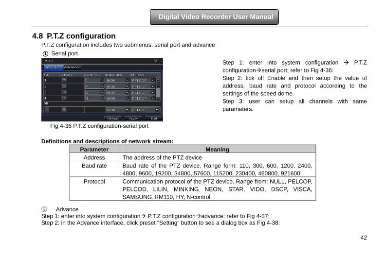
4.8 P.T.Z configuration P.T.Z configuration includes two submenus: serial port and advance
① Serial port
Step 1: enter into system configuration P.T.Z configurationserial port; refer to Fig 4-36: Step 2: tick off Enable and then setup the value of address, baud rate and protocol according to the settings of the speed dome. Step 3: user can setup all channels with same parameters.
Fig 4-36 P.T.Z configuration-serial port Definitions and descriptions of network stream:
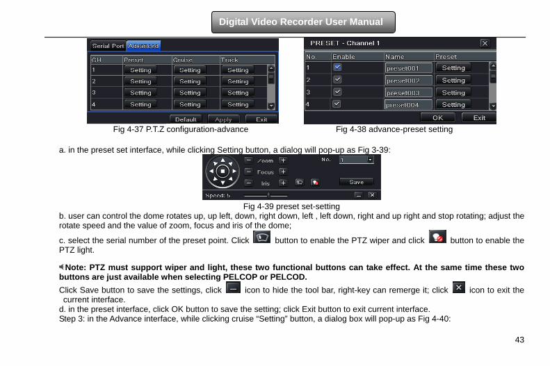
③ Advance Step 1: enter into system configuration P.T.Z configurationadvance; refer to Fig 4-37: Step 2: in the Advance interface, click preset “Setting” button to see a dialog box as Fig 4-38:
Parameter Meaning Address The address of the PTZ device
Baud rate Baud rate of the PTZ device. Range form: 110, 300, 600, 1200, 2400, 4800, 9600, 19200, 34800, 57600, 115200, 230400, 460800, 921600.
Protocol Communication protocol of the PTZ device. Range from: NULL, PELCOP, PELCOD, LILIN, MINKING, NEON, STAR, VIDO, DSCP, VISCA, SAMSUNG, RM110, HY, N-control.
43
Digital Video Recorder User Manual
Fig 4-37 P.T.Z configuration-advance Fig 4-38 advance-preset setting
a. in the preset set interface, while clicking Setting button, a dialog will pop-up as Fig 3-39:
Fig 4-39 preset set-setting
b. user can control the dome rotates up, up left, down, right down, left , left down, right and up right and stop rotating; adjust the rotate speed and the value of zoom, focus and iris of the dome;
c. select the serial number of the preset point. Click button to enable the PTZ wiper and click button to enable the PTZ light.
Note: PTZ must support wiper and light, these two functional buttons can take effect. At the same time these two buttons are just available when selecting PELCOP or PELCOD. Click Save button to save the settings, click icon to hide the tool bar, right-key can remerge it; click icon to exit the current interface.
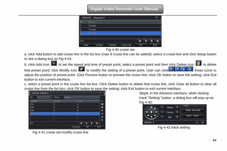
d. in the preset interface, click OK button to save the setting; click Exit button to exit current interface. Step 3: in the Advance interface, while clicking cruise “Setting” button, a dialog box will pop-up as Fig 4-40:
44
Digital Video Recorder User Manual
Fig 4-40 cruise set
a. click Add button to add cruise line in the list box (max 8 cruise line can be added); select a cruise line and click Setup button to see a dialog box as Fig 4-41:
b. click Add icon to set the speed and time of preset point; select a preset point and then click Delete icon to delete
that preset point; click Modify icon to modify the setting of a preset point. User can click those icons to adjust the position of preset point. Click Preview button to preview the cruise line; click OK button to save the setting; click Exit button to exit current interface. c. select a preset point in the cruise line list box. Click Delete button to delete that cruise line; click Clear all button to clear all cruise line from the list box; click OK button to save the setting; click Exit button to exit current interface.
Fig 4-41 cruise set-modify cruise line
Step4: in the Advance interface, while clicking track “Setting” button, a dialog box will pop-up as Fig 4-42:
Fig 4-42 track setting
45
Digital Video Recorder User Manual
a. user can control the dome rotates up, up left, down, right down, left, left down, right and up right and stop rotating; adjust the rotate speed and the value of zoom, focus and iris of the dome; click Start Record button to record the move track of PTZ; click this button again can stop record; click Start track button to play recorded track; click this button again can stop play. b. click icon to hide the tool bar, right-key can remerge it; click icon to exit the current interface.
4.9 Advanced Advanced configuration includes three submenus: reset, import/export and Block/Allow list.
4.9.1 Reset Reset all settings the device will reboot.
4.9.2 Import/Export User can export the data files into mobile storage devices as backup function, and then import specified data files from mobile storage device to DVR.
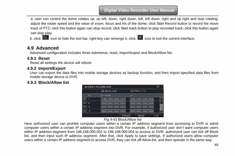
4.9.3 Block/Allow list
Fig 4-43 Block/Allow list
Here authorized user can prohibit computer users within a certain IP address segment from accessing to DVR or admit computer users within a certain IP address segment into DVR. For example, if authorized user don’t want computer users within IP address segment from 196.168.000.002 to 196.168.000.004 to access to DVR, authorized user can tick off Block list, and then input such IP address segment. After that, click Apply to save settings. If authorized users allow computer users within a certain IP address segment to access DVR, they can tick off Allow-list, and then operate in the same way.
46
Digital Video Recorder User Manual
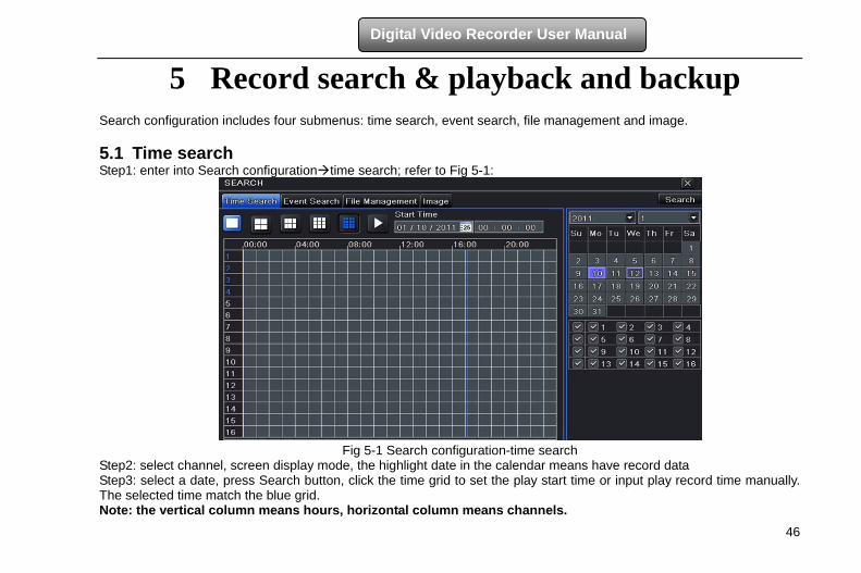
5 Record search & playback and backup Search configuration includes four submenus: time search, event search, file management and image. 5.1 Time search Step1: enter into Search configurationtime search; refer to Fig 5-1:
Fig 5-1 Search configuration-time search
Step2: select channel, screen display mode, the highlight date in the calendar means have record data Step3: select a date, press Search button, click the time grid to set the play start time or input play record time manually. The selected time match the blue grid. Note: the vertical column means hours, horizontal column means channels.
47
Digital Video Recorder User Manual
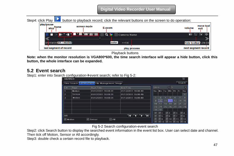
Step4: click Play button to playback record; click the relevant buttons on the screen to do operation:
Playback buttons
Note: when the monitor resolution is VGA800*600, the time search interface will appear a hide button, click this button, the whole interface can be expanded.
5.2 Event search Step1: enter into Search configurationevent search; refer to Fig 5-2:
Fig 5-2 Search configuration-event search
Step2: click Search button to display the searched event information in the event list box. User can select date and channel. Then tick off Motion, Sensor or All accordingly. Step3: double check a certain record file to playback.
48
Digital Video Recorder User Manual
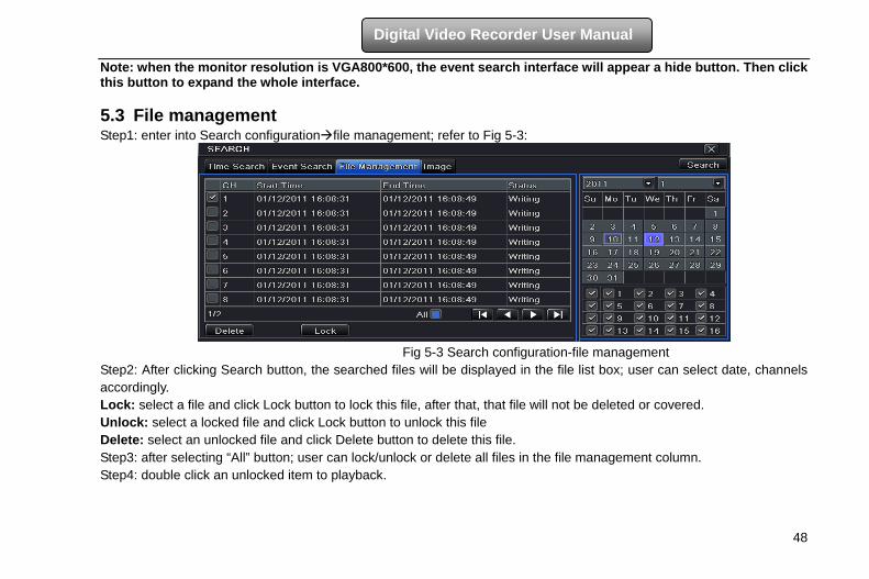
Note: when the monitor resolution is VGA800*600, the event search interface will appear a hide button. Then click this button to expand the whole interface. 5.3 File management Step1: enter into Search configurationfile management; refer to Fig 5-3:
Fig 5-3 Search configuration-file management
Step2: After clicking Search button, the searched files will be displayed in the file list box; user can select date, channels accordingly. Lock: select a file and click Lock button to lock this file, after that, that file will not be deleted or covered. Unlock: select a locked file and click Lock button to unlock this file Delete: select an unlocked file and click Delete button to delete this file. Step3: after selecting “All” button; user can lock/unlock or delete all files in the file management column. Step4: double click an unlocked item to playback.
49
Digital Video Recorder User Manual
5.4 Image In this interface, user can set start, end time and channels to search the captured images and save, lock or delete these images. There are at most 2000 images which can be saved in the SATA disk. If there are more images saved in the SATA disks than 2000 images, those additional images will supersede prior images. Double click the image with the left mouse, it will automatically playback from the time of the image captured. 5.5 Backup
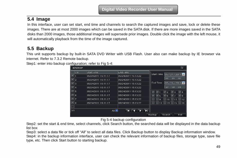
This unit supports backup by built-in SATA DVD Writer with USB Flash. User also can make backup by IE browser via internet. Refer to 7.3.2 Remote backup. Step1: enter into backup configuration; refer to Fig 5-4:
Fig 5-4 backup configuration
Step2: set the start & end time, select channels, click Search button, the searched data will be displayed in the data backup list box Step3: select a data file or tick off “All” to select all data files. Click Backup button to display Backup information window. Step4: in the backup information interface, user can check the relevant information of backup files, storage type, save file type, etc. Then click Start button to starting backup.
50
Digital Video Recorder User Manual
6 Manage DVR
6.1 Check system information Check system information includes five submenus: system, event, log, network and online user.
6.1.1 System information In this interface, user can check the hardware version, MCU version, kernel version, device ID, etc.
6.1.2 Event information In this interface, user can check record events according to the set date. Note: if there are overlapping files, a “+” character will show behind the channel ID.
6.1.3 Log information In this interface, user can check relevant log information according to set date. User can export the data files into mobile storage devices as backup function.
6.1.4 Network information In this interface, user can check relevant parameters of network.
6.1.5 Online information In this interface, user can check the details of the current connection of online users. Refresh: refresh the current interface. Disconnect: the administrator authorized to disconnect the client terminal. When disconnected, that PC will not be able to access the device within five minutes. 6.2 Manual alarm In this interface, user can check the relevant parameters of manual alarm.
51
Digital Video Recorder User Manual
6.3 Disk management 1. Format the disk Step1: enter into disk management interface Note: please format the hard disk before record. If not being formatted, it will show the status of the disk-free space, and total space show OM at the bottom of screen. Step2: click Refresh button to refresh the disk information of the list box; set the property of the disk then click Apply button to save the setting Step3: select a hard disk and click Format button to star format. Note: all recorded files in the hard disk will be lost after formatted. 2. Advanced
User may check model, S/N, firmware, health status of the disk in this interface. User also can monitor the temperature, internal circuit, dielectric material of the disk, analysis the potential problems of the disk and warn so as to protect its data. 6.4 Upgrade At present, it only supports USB update. Get the software from your vendor when there is a new software version, and make sure it is corresponding with the DVR. User can check the USB information in Disk management. Upgrade method: the user needs to copy the upgrade software which gets from vendor into the USB storage device and then connect to the USB port. Enter MenuUpgrade, the upgrade software name is displayed in the upgrade list box, select that software and then click upgrade button. It will upgrade automatically. Please wait for a while when the system is rebooted. Never cut off power during upgrading.
6.5 Logoff Click Log off icon, a log off dialogue box will popup, click OK button, the device will log off. If user wants to log in again, click icon to enter into user name and password to re-login.
52
Digital Video Recorder User Manual
7 Remote Surveillance 7.1 IE Remote Surveillance In order to view the DVR from a network it must be connected to a LAN/WAN or internet. The network setup should be done accordingly. Please refer to 4.6 Network Setup. This DVR supports IE browser, on Windows XP and Vista platform.
7.1.1 On LAN Step 1: Enter into the DVR’s Main MenuSetupNetwork interface to input IP address, Subnet Mask, etc .If using DHCP, please enable DHCP in both the DVR and the router. Step 2: Enter Record Setup to set network video parameters like resolution, frame rate etc. Step 3: Open IE on a computer on the same network. Input the IP address of the DVR in IE address bar and press enter. Step 4: IE will download ActiveX component automatically. Enter the username and password in the subsequent window
Notice: If HTTP port is not 80, other number instead, need add the port number after IP address. For example, set HTTP port as 82, need input IP address like 192.168.0.25:82. User name and password here are the same with that used on the DVR. The default is admin and 123456.
7.1.2 On WAN There are two ways for the DVR to connect to internet. 1. Connect the DVR to internet through router or virtual server Step 1: Enter into the DVR’s Main MenuSetupNetwork interface to input IP address, Subnet Mask, etc. If using DHCP, please enable DHCP in both the DVR and router. Step 2: Forward IP address and port number in Virtual Server setup of the router or virtual server. Configure the firewall to allow accessing the DVR. (If the user has enabled the UPnP function in both the DVR and router, he can skip this step.) Step 4: If users want to utilize dynamic domain name, please apply for a domain name in a DNS server supported by the DVR or router. Then add to the DVR or router. This unit supports www.dns2p.com,www.meibu.com,www.dyndns.com,and www.no-ip.com. Step 5: Open IE browser, input IP address, or dynamic domain name and enter. If HTTP port is not 80, add the port number
53
Digital Video Recorder User Manual
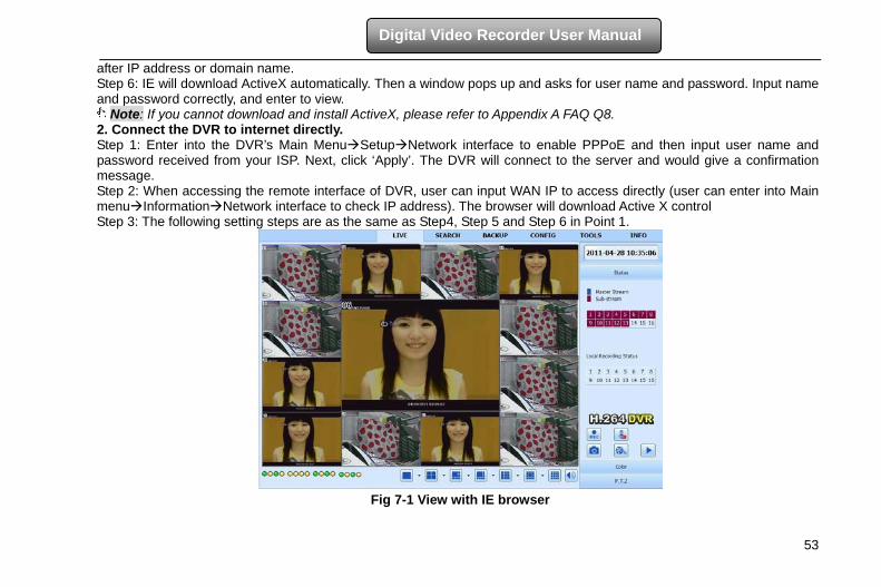
after IP address or domain name. Step 6: IE will download ActiveX automatically. Then a window pops up and asks for user name and password. Input name and password correctly, and enter to view.
Note: If you cannot download and install ActiveX, please refer to Appendix A FAQ Q8. 2. Connect the DVR to internet directly. Step 1: Enter into the DVR’s Main MenuSetupNetwork interface to enable PPPoE and then input user name and password received from your ISP. Next, click ‘Apply’. The DVR will connect to the server and would give a confirmation message. Step 2: When accessing the remote interface of DVR, user can input WAN IP to access directly (user can enter into Main menuInformationNetwork interface to check IP address). The browser will download Active X control Step 3: The following setting steps are as the same as Step4, Step 5 and Step 6 in Point 1.
Fig 7-1 View with IE browser
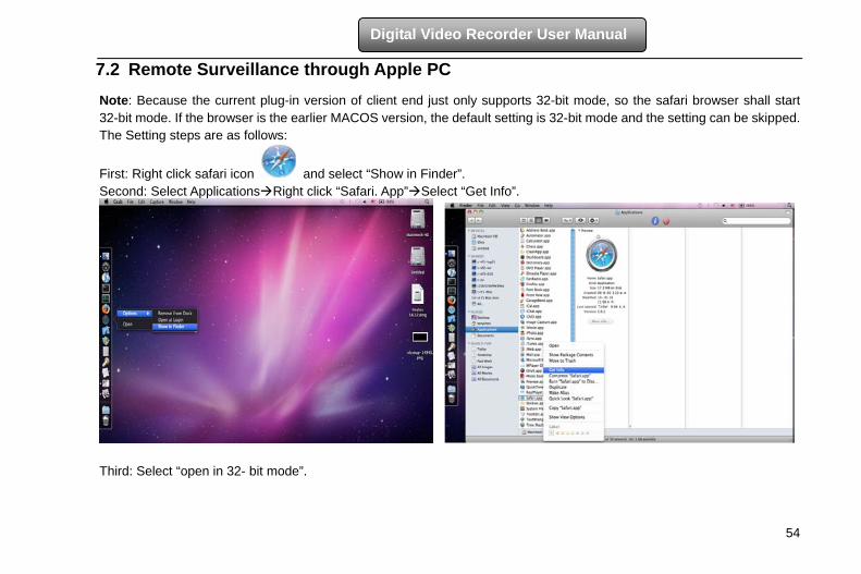
54
Digital Video Recorder User Manual
7.2 Remote Surveillance through Apple PC Note: Because the current plug-in version of client end just only supports 32-bit mode, so the safari browser shall start 32-bit mode. If the browser is the earlier MACOS version, the default setting is 32-bit mode and the setting can be skipped. The Setting steps are as follows:
First: Right click safari icon and select “Show in Finder”. Second: Select ApplicationsRight click “Safari. App”Select “Get Info”.
Third: Select “open in 32- bit mode”.
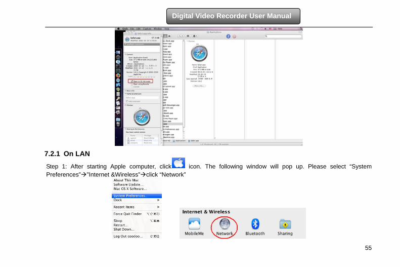
55
Digital Video Recorder User Manual
7.2.1 On LAN
Step 1: After starting Apple computer, click icon. The following window will pop up. Please select “System Preferences””Internet &Wireless”click “Network”
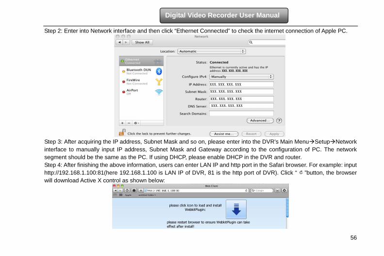
56
Digital Video Recorder User Manual
Step 2: Enter into Network interface and then click “Ethernet Connected” to check the internet connection of Apple PC.
Step 3: After acquiring the IP address, Subnet Mask and so on, please enter into the DVR’s Main MenuSetupNetwork interface to manually input IP address, Subnet Mask and Gateway according to the configuration of PC. The network segment should be the same as the PC. If using DHCP, please enable DHCP in the DVR and router. Step 4: After finishing the above information, users can enter LAN IP and http port in the Safari browser. For example: input http://192.168.1.100:81(here 192.168.1.100 is LAN IP of DVR, 81 is the http port of DVR). Click “ ”button, the browser will download Active X control as shown below:
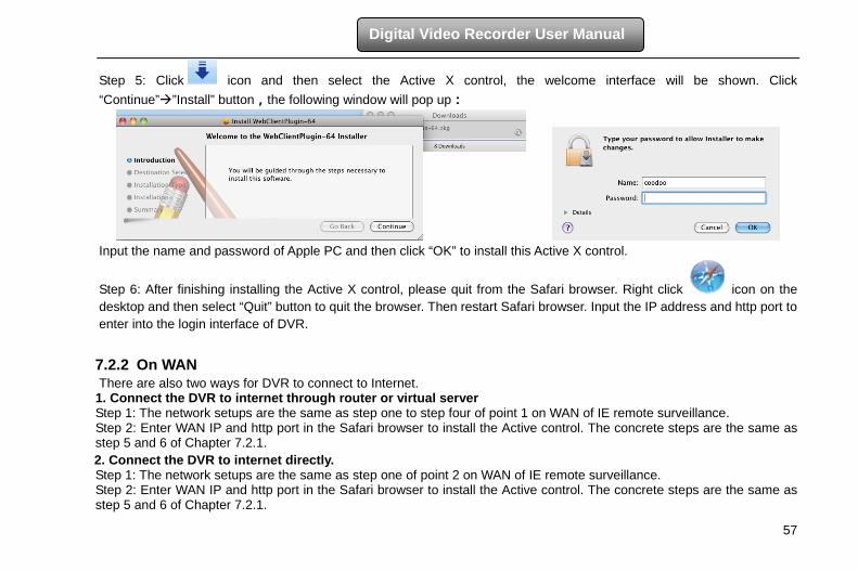
57
Digital Video Recorder User Manual
Step 5: Click icon and then select the Active X control, the welcome interface will be shown. Click “Continue””Install” button,the following window will pop up:
Input the name and password of Apple PC and then click “OK” to install this Active X control.
Step 6: After finishing installing the Active X control, please quit from the Safari browser. Right click icon on the desktop and then select “Quit” button to quit the browser. Then restart Safari browser. Input the IP address and http port to enter into the login interface of DVR.
7.2.2 On WAN There are also two ways for DVR to connect to Internet.
1. Connect the DVR to internet through router or virtual server Step 1: The network setups are the same as step one to step four of point 1 on WAN of IE remote surveillance. Step 2: Enter WAN IP and http port in the Safari browser to install the Active control. The concrete steps are the same as step 5 and 6 of Chapter 7.2.1. 2. Connect the DVR to internet directly. Step 1: The network setups are the same as step one of point 2 on WAN of IE remote surveillance. Step 2: Enter WAN IP and http port in the Safari browser to install the Active control. The concrete steps are the same as step 5 and 6 of Chapter 7.2.1.
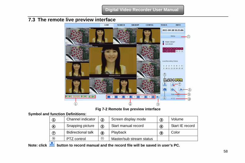
58
Digital Video Recorder User Manual
7.3 The remote live preview interface
Fig 7-2 Remote live preview interface
Symbol and function Definitions: ① Channel indicator ② Screen display mode ③ Volume
④ Snapping picture ⑤ Start manual record ⑥ Start IE record
⑦ Bidirectional talk ⑧ Playback ⑨ Color
⑩ PTZ control ⑪ Master/sub stream status
Note: click button to record manual and the record file will be saved in user’s PC.
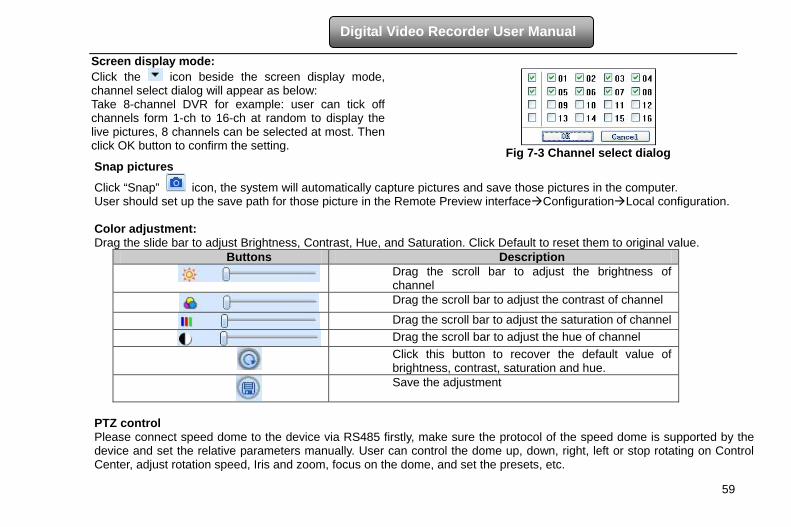
59
Digital Video Recorder User Manual
Screen display mode: Click the icon beside the screen display mode, channel select dialog will appear as below: Take 8-channel DVR for example: user can tick off channels form 1-ch to 16-ch at random to display the live pictures, 8 channels can be selected at most. Then click OK button to confirm the setting.
Fig 7-3 Channel select dialogSnap pictures
Click “Snap” icon, the system will automatically capture pictures and save those pictures in the computer. User should set up the save path for those picture in the Remote Preview interfaceConfigurationLocal configuration. Color adjustment: Drag the slide bar to adjust Brightness, Contrast, Hue, and Saturation. Click Default to reset them to original value.
Buttons Description
Drag the scroll bar to adjust the brightness of channel
Drag the scroll bar to adjust the contrast of channel
Drag the scroll bar to adjust the saturation of channel
Drag the scroll bar to adjust the hue of channel
Click this button to recover the default value of brightness, contrast, saturation and hue.
Save the adjustment
PTZ control Please connect speed dome to the device via RS485 firstly, make sure the protocol of the speed dome is supported by the device and set the relative parameters manually. User can control the dome up, down, right, left or stop rotating on Control Center, adjust rotation speed, Iris and zoom, focus on the dome, and set the presets, etc.
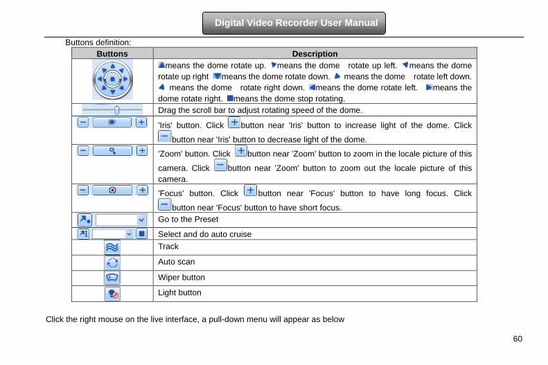
60
Digital Video Recorder User Manual
Buttons definition: Buttons Description
means the dome rotate up. means the dome rotate up left. means the dome rotate up right means the dome rotate down. means the dome rotate left down.
means the dome rotate right down. means the dome rotate left. means the dome rotate right. means the dome stop rotating.
Drag the scroll bar to adjust rotating speed of the dome.
'Iris' button. Click button near 'Iris' button to increase light of the dome. Click
button near 'Iris' button to decrease light of the dome. 'Zoom' button. Click button near 'Zoom' button to zoom in the locale picture of this
camera. Click button near 'Zoom' button to zoom out the locale picture of this camera.
'Focus' button. Click button near 'Focus' button to have long focus. Click
button near 'Focus' button to have short focus.
Go to the Preset
Select and do auto cruise
Track
Auto scan
Wiper button
Light button
Click the right mouse on the live interface, a pull-down menu will appear as below
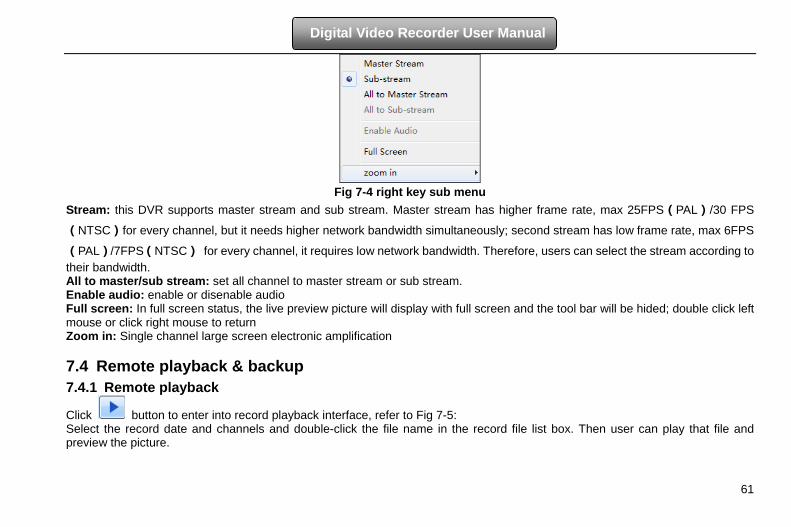
61
Digital Video Recorder User Manual
Fig 7-4 right key sub menu
Stream: this DVR supports master stream and sub stream. Master stream has higher frame rate, max 25FPS(PAL)/30 FPS
(NTSC)for every channel, but it needs higher network bandwidth simultaneously; second stream has low frame rate, max 6FPS
(PAL)/7FPS(NTSC) for every channel, it requires low network bandwidth. Therefore, users can select the stream according to their bandwidth. All to master/sub stream: set all channel to master stream or sub stream. Enable audio: enable or disenable audio Full screen: In full screen status, the live preview picture will display with full screen and the tool bar will be hided; double click left mouse or click right mouse to return Zoom in: Single channel large screen electronic amplification 7.4 Remote playback & backup 7.4.1 Remote playback
Click button to enter into record playback interface, refer to Fig 7-5: Select the record date and channels and double-click the file name in the record file list box. Then user can play that file and preview the picture.
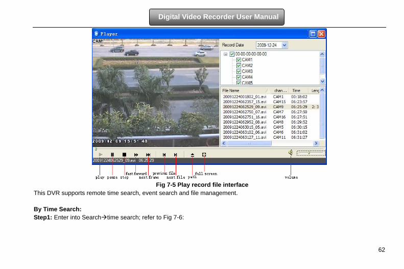
62
Digital Video Recorder User Manual
Fig 7-5 Play record file interface
This DVR supports remote time search, event search and file management. By Time Search: Step1: Enter into Searchtime search; refer to Fig 7-6:
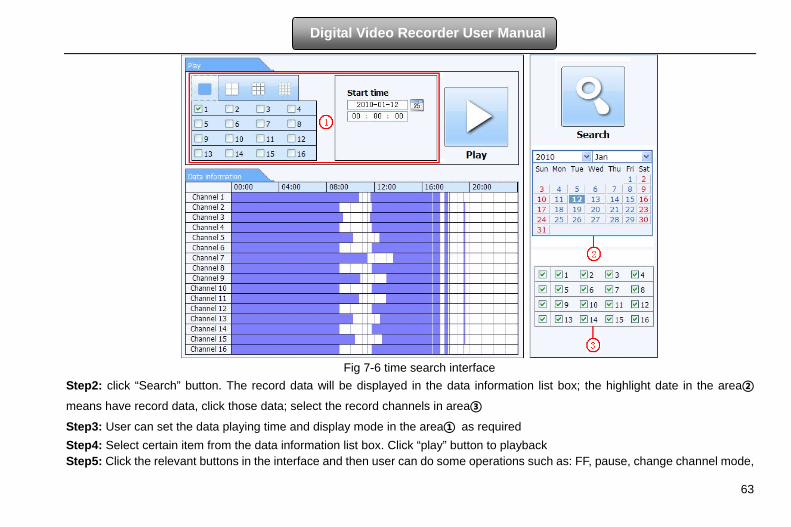
63
Digital Video Recorder User Manual
Fig 7-6 time search interface
Step2: click “Search” button. The record data will be displayed in the data information list box; the highlight date in the area②
means have record data, click those data; select the record channels in area③
Step3: User can set the data playing time and display mode in the area① as required Step4: Select certain item from the data information list box. Click “play” button to playback Step5: Click the relevant buttons in the interface and then user can do some operations such as: FF, pause, change channel mode,
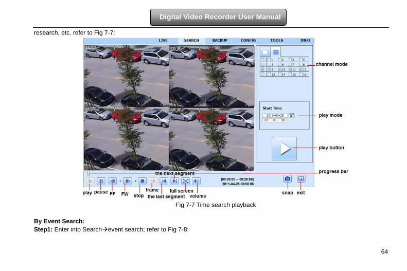
64
Digital Video Recorder User Manual
research, etc. refer to Fig 7-7:
Fig 7-7 Time search playback
By Event Search: Step1: Enter into Searchevent search; refer to Fig 7-8:
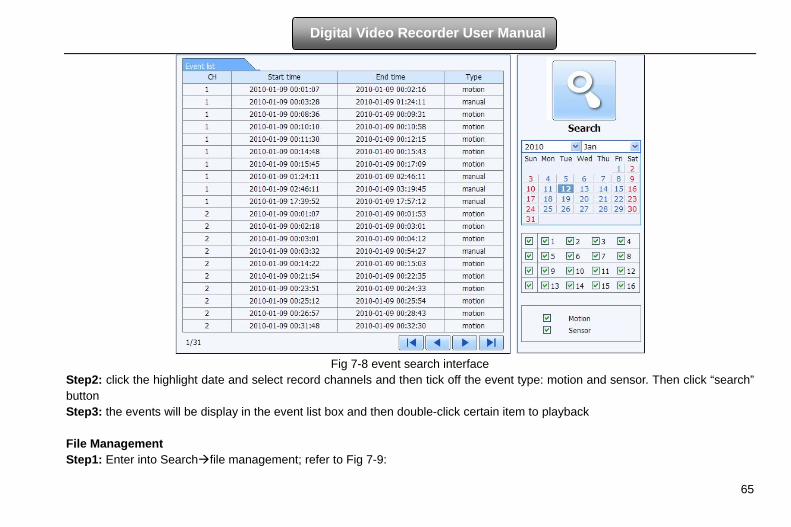
65
Digital Video Recorder User Manual
Fig 7-8 event search interface
Step2: click the highlight date and select record channels and then tick off the event type: motion and sensor. Then click “search” button Step3: the events will be display in the event list box and then double-click certain item to playback File Management Step1: Enter into Searchfile management; refer to Fig 7-9:
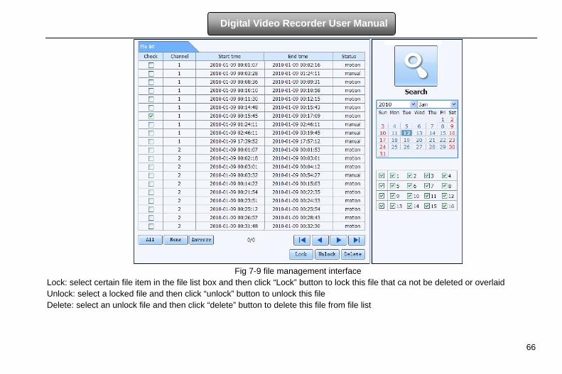
66
Digital Video Recorder User Manual
Fig 7-9 file management interface
Lock: select certain file item in the file list box and then click “Lock” button to lock this file that ca not be deleted or overlaid Unlock: select a locked file and then click “unlock” button to unlock this file Delete: select an unlock file and then click “delete” button to delete this file from file list
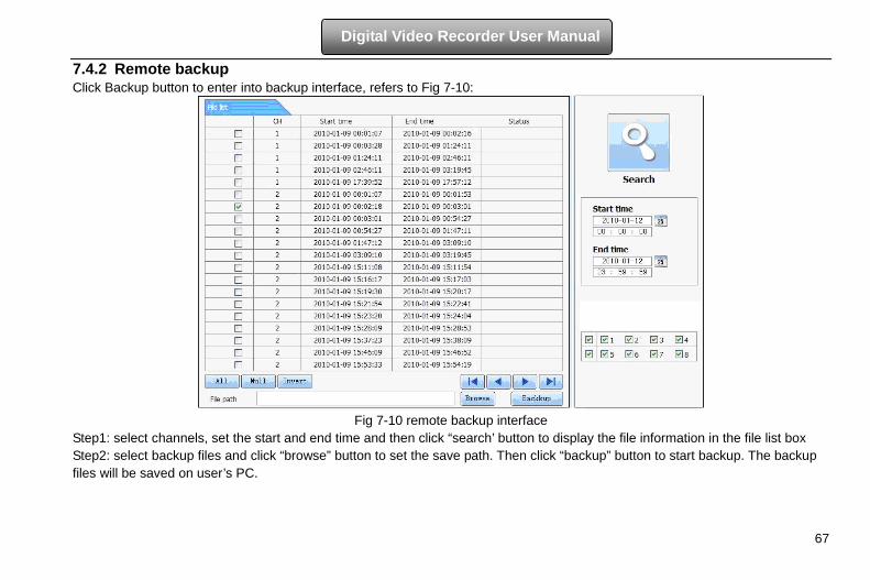
67
Digital Video Recorder User Manual
7.4.2 Remote backup Click Backup button to enter into backup interface, refers to Fig 7-10:
Fig 7-10 remote backup interface
Step1: select channels, set the start and end time and then click “search’ button to display the file information in the file list box Step2: select backup files and click “browse” button to set the save path. Then click “backup” button to start backup. The backup files will be saved on user’s PC.
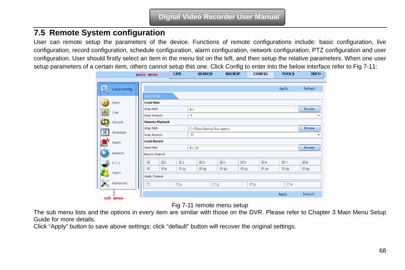
68
Digital Video Recorder User Manual
7.5 Remote System configuration User can remote setup the parameters of the device. Functions of remote configurations include: basic configuration, live configuration, record configuration, schedule configuration, alarm configuration, network configuration, PTZ configuration and user configuration. User should firstly select an item in the menu list on the left, and then setup the relative parameters. When one user setup parameters of a certain item, others cannot setup this one. Click Config to enter into the below interface refer to Fig 7-11:
Fig 7-11 remote menu setup
The sub menu lists and the options in every item are similar with those on the DVR. Please refer to Chapter 3 Main Menu Setup Guide for more details. Click “Apply” button to save above settings; click “default” button will recover the original settings.
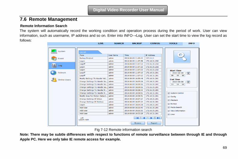
69
Digital Video Recorder User Manual
7.6 Remote Management Remote Information Search The system will automatically record the working condition and operation process during the period of work. User can view information, such as username, IP address and so on. Enter into INFO→Log. User can set the start time to view the log record as follows:
Fig 7-12 Remote information search
Note: There may be subtle differences with respect to functions of remote surveillance between through IE and through Apple PC. Here we only take IE remote access for example.
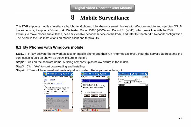
70
Digital Video Recorder User Manual
8 Mobile Surveillance
This DVR supports mobile surveillance by Iphone, Gphone,blackberry or smart phones with Windows mobile and symbian OS. At the same time, it supports 3G network. We tested Dopod D600 (WM5) and Dopod S1 (WM6), which work fine with the DVR. It wants to make mobile surveillance, need first enable network service on the DVR, and refer to Chapter 4.6 Network configuration. The below is the use instructions on mobile client end for two OS.
8.1 By Phones with Windows mobile Step1: Firstly activate the network access on mobile phone and then run “Internet Explorer”. Input the server’s address and the connection is built up shown as below picture in the left: Step2:Click on the software name. A dialog box pops up as below picture in the middle: Step3:Click “Yes” to start downloading and installing: Step4:PCam will be opened automatically after installed. Refer picture in the right:
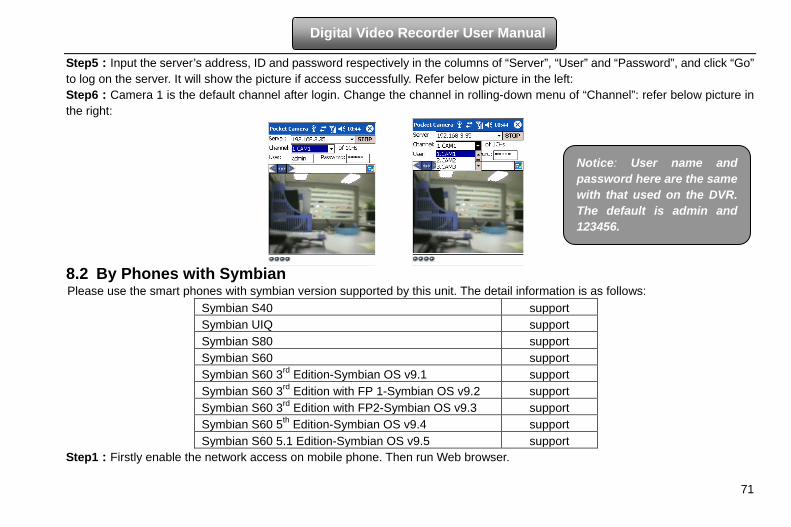
71
Digital Video Recorder User Manual
Step5:Input the server’s address, ID and password respectively in the columns of “Server”, “User” and “Password”, and click “Go” to log on the server. It will show the picture if access successfully. Refer below picture in the left: Step6:Camera 1 is the default channel after login. Change the channel in rolling-down menu of “Channel”: refer below picture in the right:
8.2 By Phones with Symbian Please use the smart phones with symbian version supported by this unit. The detail information is as follows:
Symbian S40 support Symbian UIQ support Symbian S80 support Symbian S60 support Symbian S60 3rd Edition-Symbian OS v9.1 support Symbian S60 3rd Edition with FP 1-Symbian OS v9.2 support Symbian S60 3rd Edition with FP2-Symbian OS v9.3 support Symbian S60 5th Edition-Symbian OS v9.4 support Symbian S60 5.1 Edition-Symbian OS v9.5 support
Step1:Firstly enable the network access on mobile phone. Then run Web browser.
Notice: User name and password here are the same with that used on the DVR. The default is admin and 123456.
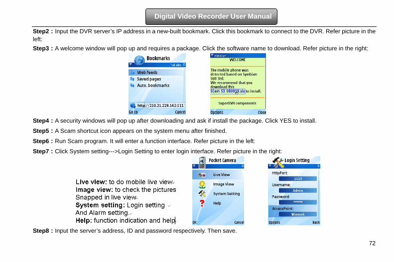
72
Digital Video Recorder User Manual
Step2:Input the DVR server’s IP address in a new-built bookmark. Click this bookmark to connect to the DVR. Refer picture in the left: Step3:A welcome window will pop up and requires a package. Click the software name to download. Refer picture in the right:
Step4:A security windows will pop up after downloading and ask if install the package. Click YES to install.
Step5:A Scam shortcut icon appears on the system menu after finished.
Step6:Run Scam program. It will enter a function interface. Refer picture in the left:
Step7:Click System setting--->Login Setting to enter login interface. Refer picture in the right:
Step8:Input the server’s address, ID and password respectively. Then save.
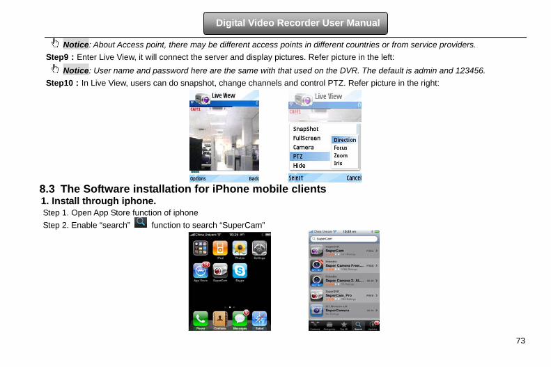
73
Digital Video Recorder User Manual
Notice: About Access point, there may be different access points in different countries or from service providers. Step9:Enter Live View, it will connect the server and display pictures. Refer picture in the left:
Notice: User name and password here are the same with that used on the DVR. The default is admin and 123456. Step10:In Live View, users can do snapshot, change channels and control PTZ. Refer picture in the right:
8.3 The Software installation for iPhone mobile clients 1. Install through iphone. Step 1. Open App Store function of iphone Step 2. Enable “search” function to search “SuperCam”
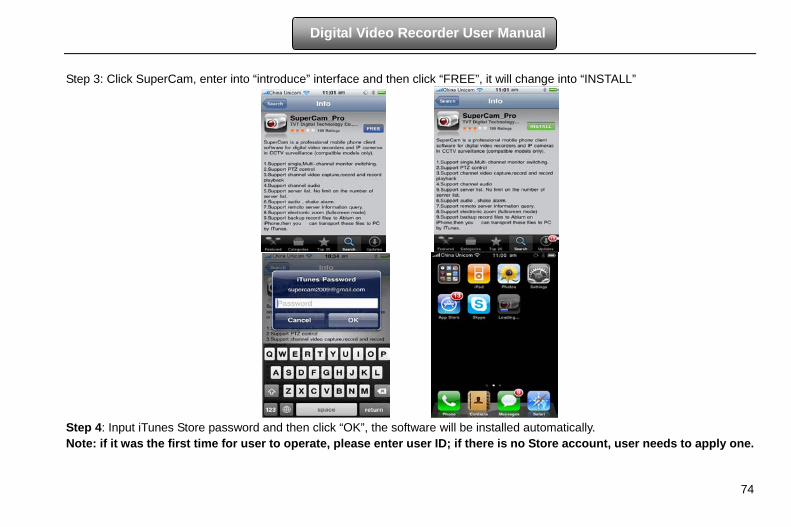
74
Digital Video Recorder User Manual
Step 3: Click SuperCam, enter into “introduce” interface and then click “FREE”, it will change into “INSTALL”
Step 4: Input iTunes Store password and then click “OK”, the software will be installed automatically. Note: if it was the first time for user to operate, please enter user ID; if there is no Store account, user needs to apply one.
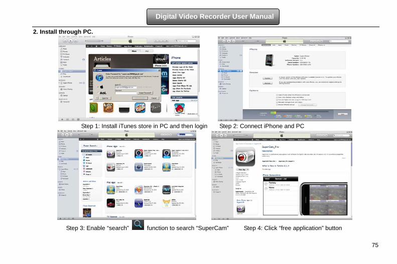
75
Digital Video Recorder User Manual
2. Install through PC.
Step 1: Install iTunes store in PC and then login Step 2: Connect iPhone and PC
Step 3: Enable “search” function to search “SuperCam” Step 4: Click “free application” button
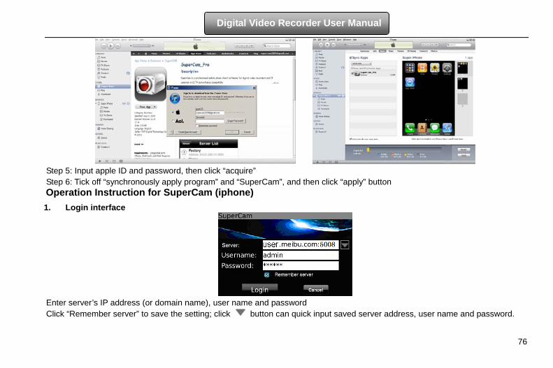
76
Digital Video Recorder User Manual
Step 5: Input apple ID and password, then click “acquire” Step 6: Tick off “synchronously apply program” and “SuperCam”, and then click “apply” button Operation Instruction for SuperCam (iphone) 1. Login interface
Enter server’s IP address (or domain name), user name and password Click “Remember server” to save the setting; click button can quick input saved server address, user name and password.
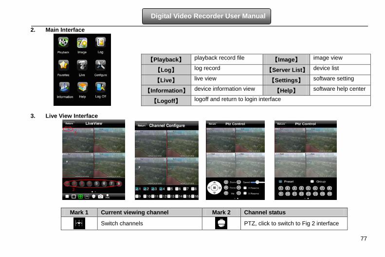
77
Digital Video Recorder User Manual
2. Main Interface
3. Live View Interface
Mark 1 Current viewing channel Mark 2 Channel status
Switch channels
PTZ, click to switch to Fig 2 interface
【Playback】 playback record file 【Image】 image view
【Log】 log record 【Server List】 device list
【Live】 live view 【Settings】 software setting
【Information】 device information view 【Help】 software help center
【Logoff】 logoff and return to login interface
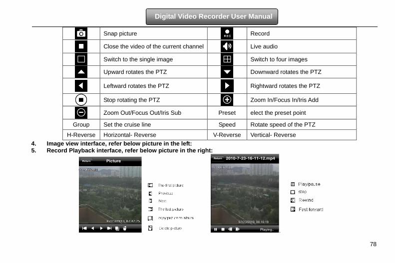
78
Digital Video Recorder User Manual
Snap picture
Record
Close the video of the current channel
Live audio
Switch to the single image
Switch to four images
Upward rotates the PTZ
Downward rotates the PTZ
Leftward rotates the PTZ
Rightward rotates the PTZ
Stop rotating the PTZ
Zoom In/Focus In/Iris Add
Zoom Out/Focus Out/Iris Sub Preset elect the preset point
Group Set the cruise line Speed Rotate speed of the PTZ
H-Reverse Horizontal- Reverse V-Reverse Vertical- Reverse 4. Image view interface, refer below picture in the left: 5. Record Playback interface, refer below picture in the right:
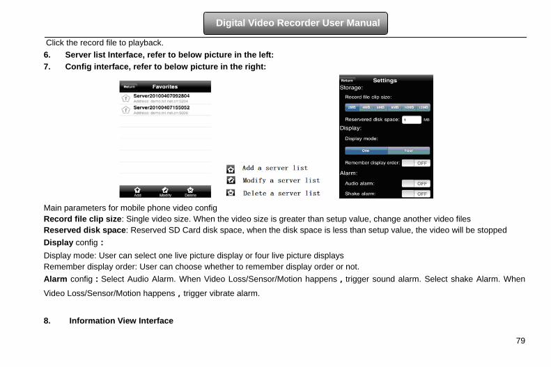
79
Digital Video Recorder User Manual
Click the record file to playback. 6. Server list Interface, refer to below picture in the left: 7. Config interface, refer to below picture in the right:
Main parameters for mobile phone video config Record file clip size: Single video size. When the video size is greater than setup value, change another video files Reserved disk space: Reserved SD Card disk space, when the disk space is less than setup value, the video will be stopped Display config: Display mode: User can select one live picture display or four live picture displays Remember display order: User can choose whether to remember display order or not. Alarm config:Select Audio Alarm. When Video Loss/Sensor/Motion happens,trigger sound alarm. Select shake Alarm. When
Video Loss/Sensor/Motion happens,trigger vibrate alarm.
8. Information View Interface
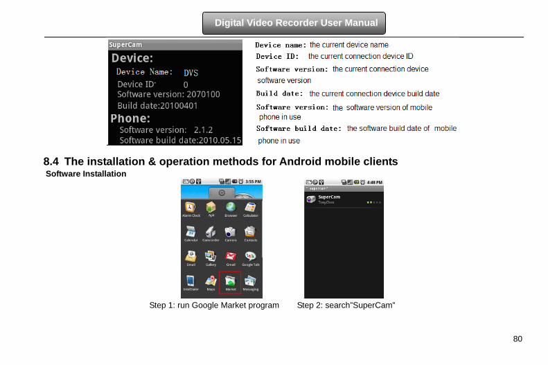
80
Digital Video Recorder User Manual
8.4 The installation & operation methods for Android mobile clients Software Installation
Step 1: run Google Market program Step 2: search”SuperCam”
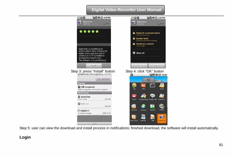
81
Digital Video Recorder User Manual
Step 3: press “Install” button Step 4: click “OK” button
Step 5: user can view the download and install process in notifications; finished download, the software will install automatically. Login
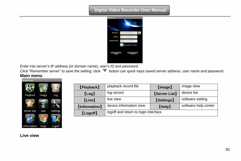
82
Digital Video Recorder User Manual
Enter into server’s IP address (or domain name), user’s ID and password. Click “Remember server” to save the setting; click button can quick input saved server address, user name and password. Main menu
Live view
【Playback】 playback record file 【Image】 image view
【Log】 log record 【Server List】 device list
【Live】 live view 【Settings】 software setting
【Information】 device information view 【Help】 software help center
【Logoff】 logoff and return to login interface
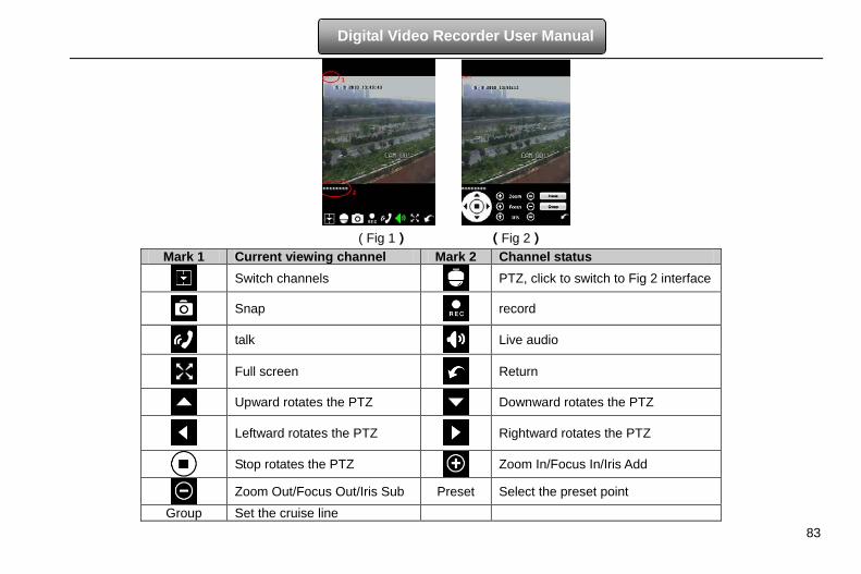
83
Digital Video Recorder User Manual
( Fig 1) (Fig 2)
Mark 1 Current viewing channel Mark 2 Channel status
Switch channels
PTZ, click to switch to Fig 2 interface
Snap record
talk
Live audio
Full screen
Return
Upward rotates the PTZ
Downward rotates the PTZ
Leftward rotates the PTZ Rightward rotates the PTZ
Stop rotates the PTZ
Zoom In/Focus In/Iris Add
Zoom Out/Focus Out/Iris Sub Preset Select the preset point
Group Set the cruise line
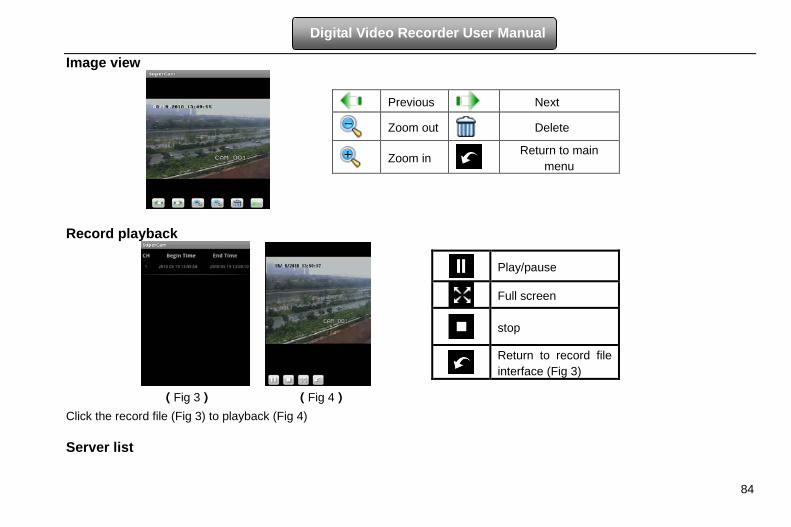
84
Digital Video Recorder User Manual
Image view
Record playback
(Fig 3) (Fig 4)
Click the record file (Fig 3) to playback (Fig 4) Server list
Previous Next
Zoom out Delete
Zoom in Return to main
menu
Play/pause
Full screen
stop
Return to record file interface (Fig 3)
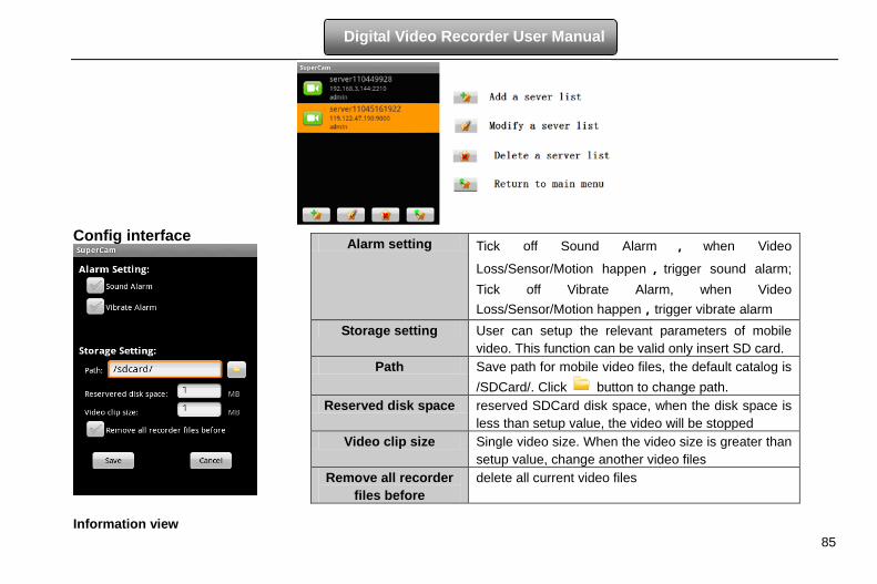
85
Digital Video Recorder User Manual
Config interface
Information view
Alarm setting Tick off Sound Alarm , when Video
Loss/Sensor/Motion happen , trigger sound alarm; Tick off Vibrate Alarm, when Video Loss/Sensor/Motion happen,trigger vibrate alarm
Storage setting User can setup the relevant parameters of mobile video. This function can be valid only insert SD card.
Path Save path for mobile video files, the default catalog is /SDCard/. Click button to change path.
Reserved disk space reserved SDCard disk space, when the disk space is less than setup value, the video will be stopped
Video clip size Single video size. When the video size is greater than setup value, change another video files
Remove all recorder files before
delete all current video files
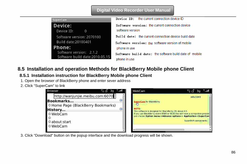
86
Digital Video Recorder User Manual
8.5 Installation and operation Methods for BlackBerry Mobile phone Client 8.5.1 Installation instruction for BlackBerry Mobile phone Client 1. Open the browser of BlackBerry phone and enter sever address 2. Click “SuperCam” to link
3. Click “Download” button on the popup interface and the download progress will be shown.
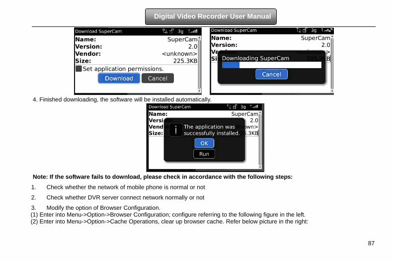
87
Digital Video Recorder User Manual
4. Finished downloading, the software will be installed automatically.
Note: If the software fails to download, please check in accordance with the following steps:
1. Check whether the network of mobile phone is normal or not
2. Check whether DVR server connect network normally or not
3. Modify the option of Browser Configuration. (1) Enter into Menu->Option->Browser Configuration; configure referring to the following figure in the left. (2) Enter into Menu->Option->Cache Operations, clear up browser cache. Refer below picture in the right:
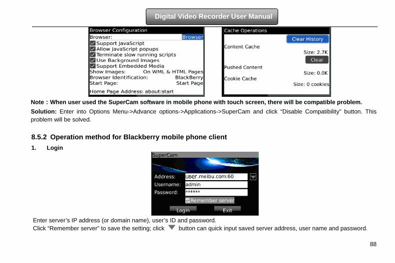
88
Digital Video Recorder User Manual
Note:When user used the SuperCam software in mobile phone with touch screen, there will be compatible problem. Solution: Enter into Options Menu->Advance options->Applications->SuperCam and click “Disable Compatibility” button. This problem will be solved. 8.5.2 Operation method for Blackberry mobile phone client 1. Login
Enter server’s IP address (or domain name), user’s ID and password. Click “Remember server” to save the setting; click button can quick input saved server address, user name and password.
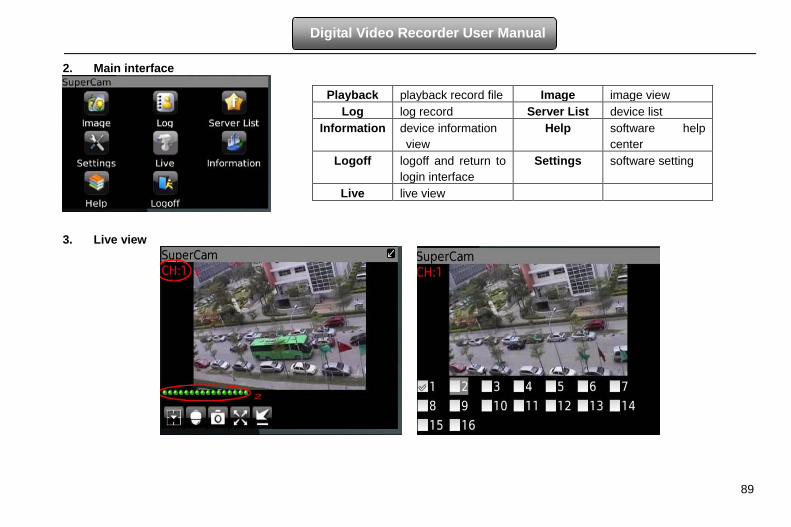
89
Digital Video Recorder User Manual
2. Main interface
3. Live view
Playback playback record file Image image view Log log record Server List device list
Information device information view
Help software help center
Logoff logoff and return to login interface
Settings software setting
Live live view
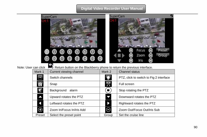
90
Digital Video Recorder User Manual
Note: User can click Return button on the Blackberry phone to return the previous interface. Mark 1 Current viewing channel Mark 2 Channel status
Switch channels PTZ, click to switch to Fig 2 interface
Snap Full screen
Background alarm
Stop rotating the PTZ
Upward rotates the PTZ Downward rotates the PTZ
Leftward rotates the PTZ Rightward rotates the PTZ
Zoom In/Focus In/Iris Add
Zoom Out/Focus Out/Iris Sub
Preset Select the preset point Group Set the cruise line
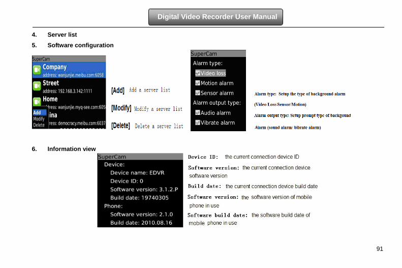
91
Digital Video Recorder User Manual
4. Server list
5. Software configuration
6. Information view
92
Digital Video Recorder User Manual
Appendix A FAQ Q1. Why the DVR cannot start after connected to the power? a. The adapter has been damaged. Please change an adapter b. The power of the adapter is not enough. Please remove the HDD to check c. Hardware problem Q2. There is not menu output or only has live image display a. Check up whether other devices can display menu or long press ESC key to wait for login dialog box to appear. Q3. The indicator of the DVR lights, but no output. Why? a. The power of the adapter is not enough. Please remove the HDD or change an adapter to try. b. The video format of the DVR is different from that of the monitor. c. Connection problem. Please check the cable and the ports of monitor and DVR. Q4. Why are no images displayed on parts or all of the channels of the DVR? a. Connection problem. Please check the cable and the ports of camera and DVR. b. Camera problem. Please check the cameras. c. The video format of the DVR is different from that of the cameras. Please change DVR system format. Q5. Cannot find HDD a. The power of the adapter is not enough. Please change an adapter to try. b. Connection problem. Please check the power and data cables. c. The HDD is damaged. Change a new one.
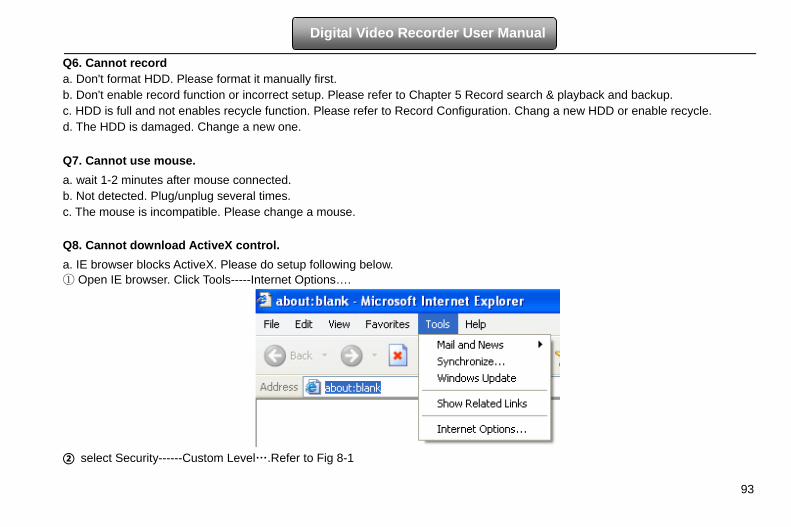
93
Digital Video Recorder User Manual
Q6. Cannot record a. Don't format HDD. Please format it manually first. b. Don't enable record function or incorrect setup. Please refer to Chapter 5 Record search & playback and backup. c. HDD is full and not enables recycle function. Please refer to Record Configuration. Chang a new HDD or enable recycle. d. The HDD is damaged. Change a new one. Q7. Cannot use mouse. a. wait 1-2 minutes after mouse connected. b. Not detected. Plug/unplug several times. c. The mouse is incompatible. Please change a mouse. Q8. Cannot download ActiveX control. a. IE browser blocks ActiveX. Please do setup following below. ① Open IE browser. Click Tools-----Internet Options….
② select Security------Custom Level….Refer to Fig 8-1
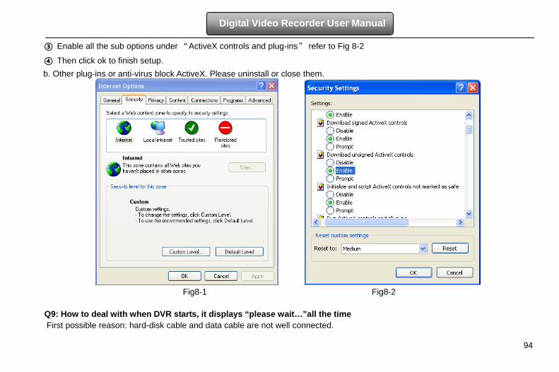
94
Digital Video Recorder User Manual
③ Enable all the sub options under “ActiveX controls and plug-ins” refer to Fig 8-2
④ Then click ok to finish setup. b. Other plug-ins or anti-virus block ActiveX. Please uninstall or close them.
Fig8-1 Fig8-2
Q9: How to deal with when DVR starts, it displays “please wait…”all the time First possible reason: hard-disk cable and data cable are not well connected.
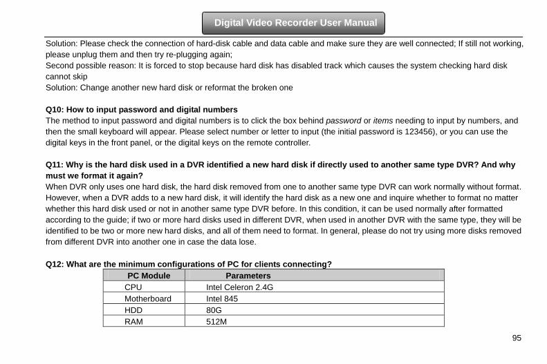
95
Digital Video Recorder User Manual
Solution: Please check the connection of hard-disk cable and data cable and make sure they are well connected; If still not working, please unplug them and then try re-plugging again; Second possible reason: It is forced to stop because hard disk has disabled track which causes the system checking hard disk cannot skip Solution: Change another new hard disk or reformat the broken one Q10: How to input password and digital numbers The method to input password and digital numbers is to click the box behind password or items needing to input by numbers, and then the small keyboard will appear. Please select number or letter to input (the initial password is 123456), or you can use the digital keys in the front panel, or the digital keys on the remote controller. Q11: Why is the hard disk used in a DVR identified a new hard disk if directly used to another same type DVR? And why must we format it again? When DVR only uses one hard disk, the hard disk removed from one to another same type DVR can work normally without format. However, when a DVR adds to a new hard disk, it will identify the hard disk as a new one and inquire whether to format no matter whether this hard disk used or not in another same type DVR before. In this condition, it can be used normally after formatted according to the guide; if two or more hard disks used in different DVR, when used in another DVR with the same type, they will be identified to be two or more new hard disks, and all of them need to format. In general, please do not try using more disks removed from different DVR into another one in case the data lose. Q12: What are the minimum configurations of PC for clients connecting?
PC Module Parameters CPU Intel Celeron 2.4G Motherboard Intel 845 HDD 80G RAM 512M
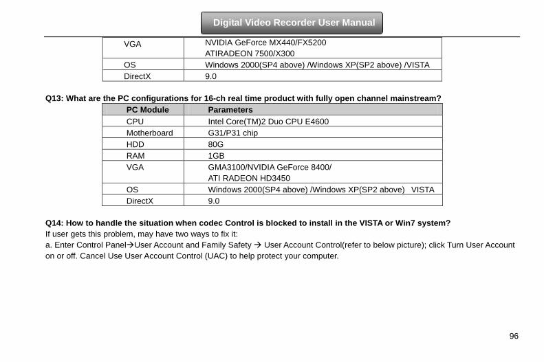
96
Digital Video Recorder User Manual
VGA NVIDIA GeForce MX440/FX5200 ATIRADEON 7500/X300
OS Windows 2000(SP4 above) /Windows XP(SP2 above) /VISTA DirectX 9.0
Q13: What are the PC configurations for 16-ch real time product with fully open channel mainstream?
PC Module Parameters CPU Intel Core(TM)2 Duo CPU E4600 Motherboard G31/P31 chip HDD 80G RAM 1GB VGA GMA3100/NVIDIA GeForce 8400/
ATI RADEON HD3450 OS Windows 2000(SP4 above) /Windows XP(SP2 above) VISTA DirectX 9.0
Q14: How to handle the situation when codec Control is blocked to install in the VISTA or Win7 system? If user gets this problem, may have two ways to fix it: a. Enter Control PanelUser Account and Family Safety User Account Control(refer to below picture); click Turn User Account on or off. Cancel Use User Account Control (UAC) to help protect your computer.
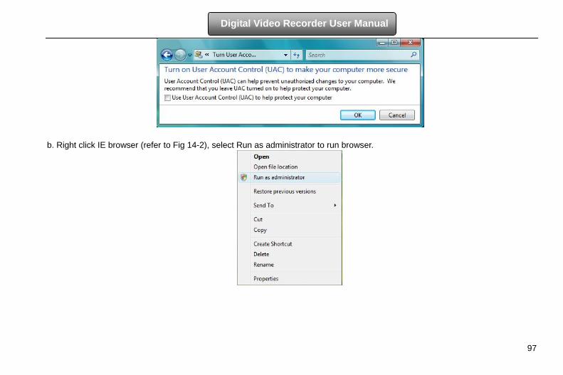
97
Digital Video Recorder User Manual
b. Right click IE browser (refer to Fig 14-2), select Run as administrator to run browser.
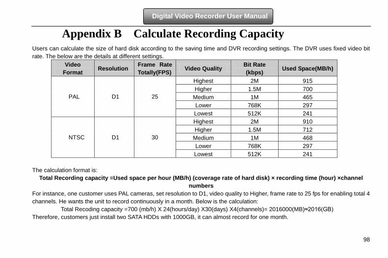
98
Digital Video Recorder User Manual
Appendix B Calculate Recording Capacity Users can calculate the size of hard disk according to the saving time and DVR recording settings. The DVR uses fixed video bit rate. The below are the details at different settings.
Video Format Resolution Frame Rate
Totally(FPS) Video Quality Bit Rate (kbps) Used Space(MB/h)
PAL
D1
25
Highest 2M 915 Higher 1.5M 700
Medium 1M 465 Lower 768K 297 Lowest 512K 241
NTSC D1 30
Highest 2M 910 Higher 1.5M 712
Medium 1M 468 Lower 768K 297 Lowest 512K 241
The calculation format is:
Total Recording capacity =Used space per hour (MB/h) (coverage rate of hard disk) × recording time (hour) ×channel numbers
For instance, one customer uses PAL cameras, set resolution to D1, video quality to Higher, frame rate to 25 fps for enabling total 4 channels. He wants the unit to record continuously in a month. Below is the calculation:
Total Recoding capacity =700 (mb/h) X 24(hours/day) X30(days) X4(channels)= 2016000(MB)≈2016(GB) Therefore, customers just install two SATA HDDs with 1000GB, it can almost record for one month.
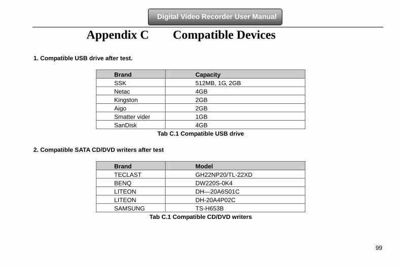
99
Digital Video Recorder User Manual
Appendix C Compatible Devices 1. Compatible USB drive after test.
Brand Capacity SSK 512MB, 1G, 2GB Netac 4GB Kingston 2GB Aigo 2GB Smatter vider 1GB SanDisk 4GB
Tab C.1 Compatible USB drive 2. Compatible SATA CD/DVD writers after test
Brand Model TECLAST GH22NP20/TL-22XD BENQ DW220S-0K4 LITEON DH—20A6S01C LITEON DH-20A4P02C SAMSUNG TS-H653B
Tab C.1 Compatible CD/DVD writers
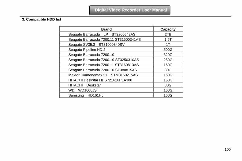
100
Digital Video Recorder User Manual
3. Compatible HDD list
Brand Capacity Seagate Barracuda LP ST3200542AS 2TB Seagate Barracuda 7200.11 ST31500341AS 1.5T Seagate SV35.3 ST31000340SV 1T Seagate Pipeline HD.2 500G Seagate Barracuda 7200.10 320G Seagate Barracuda 7200.10 ST3250310AS 250G Seagate Barracuda 7200.11 ST3160813AS 160G Seagate Barracuda 7200.10 ST380815AS 80G Maxtor Diamondmax 21 STM3160215AS 160G HITACHI Deskstar HDS721616PLA380 160G HITACHI Deskstar 80G WD WD1600JS 160G Samsung HD161HJ 160G
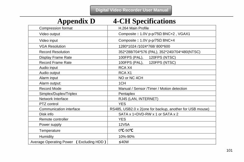
101
Digital Video Recorder User Manual
Appendix D 4-CH Specifications Compression format H.264 Main Profile Video output Composite:1.0V p-p/75Ω BNC×2 , VGAX1
Video input Composite:1.0V p-p/75Ω BNC×4 VGA Resolution 1280*1024 /1024*768/ 800*600 Record Resolution 352*288/704*576 (PAL), 352*240/704*480(NTSC) Display Frame Rate 100FPS (PAL), 120FPS (NTSC) Record Frame Rate 100FPS (PAL), 120FPS (NTSC) Audio input RCA X4 Audio output RCA X1 Alarm input NO or NC 4CH Alarm output: 1CH Record Mode Manual / Sensor /Timer / Motion detection Simplex/Duplex/Triplex Pentaplex Network Interface RJ45 (LAN, INTERNET) PTZ control YES Communication interface RS485, USB2.0 x 2(one for backup, another for USB mouse) Disk info SATA x 1+DVD-RW x 1 or SATA x 2 Remote controller YES Power supply 12V5A Temperature 0℃-50℃
Humidity 10%-90% Average Operating Power (Excluding HDD) ≤40W
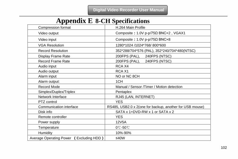
102
Digital Video Recorder User Manual
Appendix E 8-CH Specifications Compression format H.264 Main Profile Video output Composite:1.0V p-p/75Ω BNC×2 , VGAX1
Video input Composite:1.0V p-p/75Ω BNC×8 VGA Resolution 1280*1024 /1024*768/ 800*600 Record Resolution 352*288/704*576 (PAL), 352*240/704*480(NTSC) Display Frame Rate 200FPS (PAL), 240FPS (NTSC) Record Frame Rate 200FPS (PAL), 240FPS (NTSC) Audio input RCA X4 Audio output RCA X1 Alarm input NO or NC 8CH Alarm output: 1CH Record Mode Manual / Sensor /Timer / Motion detection Simplex/Duplex/Triplex Pentaplex Network Interface RJ45 (LAN, INTERNET) PTZ control YES Communication interface RS485, USB2.0 x 2(one for backup, another for USB mouse) Disk info SATA x 1+DVD-RW x 1 or SATA x 2 Remote controller YES Power supply 12V5A Temperature 0℃-50℃ Humidity 10%-90%
Average Operating Power (Excluding HDD) ≤40W
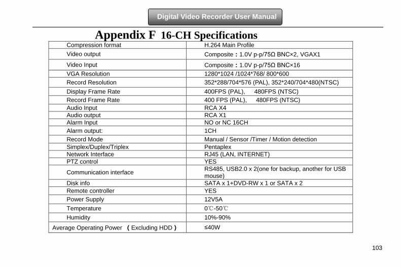
103
Digital Video Recorder User Manual
Appendix F 16-CH Specifications Compression format H.264 Main Profile Video output Composite:1.0V p-p/75Ω BNC×2, VGAX1
Video Input Composite:1.0V p-p/75Ω BNC×16 VGA Resolution 1280*1024 /1024*768/ 800*600 Record Resolution 352*288/704*576 (PAL), 352*240/704*480(NTSC) Display Frame Rate 400FPS (PAL), 480FPS (NTSC) Record Frame Rate 400 FPS (PAL), 480FPS (NTSC) Audio Input RCA X4 Audio output RCA X1 Alarm Input NO or NC 16CH Alarm output: 1CH Record Mode Manual / Sensor /Timer / Motion detection Simplex/Duplex/Triplex Pentaplex Network Interface RJ45 (LAN, INTERNET) PTZ control YES
Communication interface RS485, USB2.0 x 2(one for backup, another for USB mouse)
Disk info SATA x 1+DVD-RW x 1 or SATA x 2 Remote controller YES Power Supply 12V5A Temperature 0℃-50℃ Humidity 10%-90%
Average Operating Power (Excluding HDD) ≤40W