Embed Size (px)
Citation preview
7/28/2019 Dwell Calibration
http://slidepdf.com/reader/full/dwell-calibration 1/16
Dwell Calibration
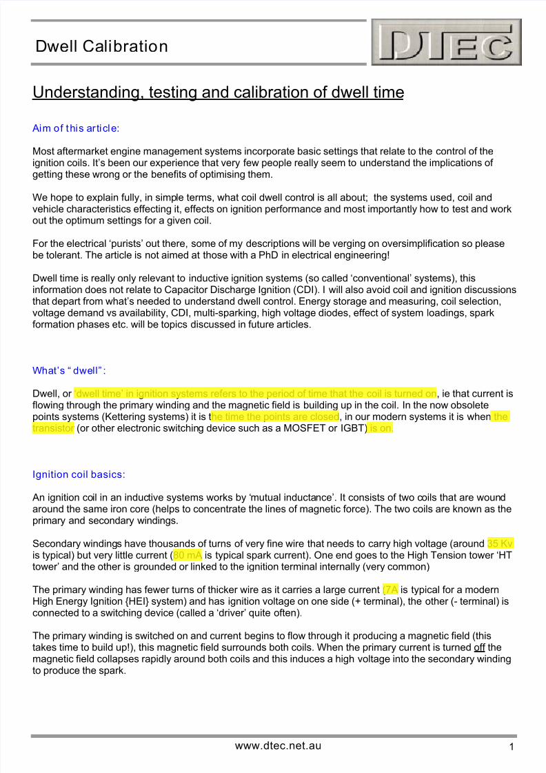
Understanding, testing and calibration of dwell time
Aim of this article:
Most aftermarket engine management systems incorporate basic settings that relate to the control of theignition coils. It’s been our experience that very few people really seem to understand the implications of getting these wrong or the benefits of optimising them.
We hope to explain fully, in simple terms, what coil dwell control is all about; the systems used, coil andvehicle characteristics effecting it, effects on ignition performance and most importantly how to test and workout the optimum settings for a given coil.
For the electrical ‘purists’ out there, some of my descriptions will be verging on oversimplification so pleasebe tolerant. The article is not aimed at those with a PhD in electrical engineering!
Dwell time is really only relevant to inductive ignition systems (so called ‘conventional’ systems), thisinformation does not relate to Capacitor Discharge Ignition (CDI). I will also avoid coil and ignition discussionsthat depart from what’s needed to understand dwell control. Energy storage and measuring, coil selection,voltage demand vs availability, CDI, multi-sparking, high voltage diodes, effect of system loadings, sparkformation phases etc. will be topics discussed in future articles.
What’s “ dwell” :
Dwell, or ‘dwell time’ in ignition systems refers to the period of time that the coil is turned on, ie that current is
flowing through the primary winding and the magnetic field is building up in the coil. In the now obsoletepoints systems (Kettering systems) it is the time the points are closed, in our modern systems it is when thetransistor (or other electronic switching device such as a MOSFET or IGBT) is on.
Ignition coil basics:
An ignition coil in an inductive systems works by ‘mutual inductance’. It consists of two coils that are woundaround the same iron core (helps to concentrate the lines of magnetic force). The two coils are known as theprimary and secondary windings.
Secondary windings have thousands of turns of very fine wire that needs to carry high voltage (around 35 Kvis typical) but very little current (80 mA is typical spark current). One end goes to the High Tension tower ‘HTtower’ and the other is grounded or linked to the ignition terminal internally (very common)
The primary winding has fewer turns of thicker wire as it carries a large current (7A is typical for a modernHigh Energy Ignition HEI system) and has ignition voltage on one side (+ terminal), the other (- terminal) isconnected to a switching device (called a ‘driver’ quite often).
The primary winding is switched on and current begins to flow through it producing a magnetic field (thistakes time to build up!), this magnetic field surrounds both coils. When the primary current is turned off themagnetic field collapses rapidly around both coils and this induces a high voltage into the secondary windingto produce the spark.
www.dtec.net.au 1
7/28/2019 Dwell Calibration
http://slidepdf.com/reader/full/dwell-calibration 2/16
Dwell Calibration
Iron
core
+ terminal, 12V suppl y
Primarywinding
Secondarywinding
- terminal,
to switching
Switching device,HT terminal to spark plugsCan be internal in
coil or external
ground
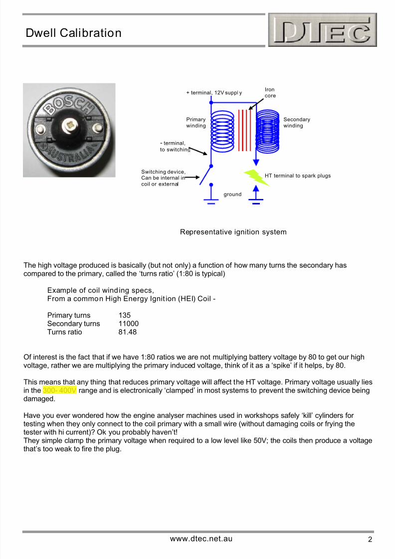
Representative ignition system
The high voltage produced is basically (but not only) a function of how many turns the secondary hascompared to the primary, called the ‘turns ratio’ (1:80 is typical)
Example of coil wind ing specs,From a common High Energy Ignit ion (HEI) Coil -
Primary turns 135Secondary turns 11000Turns ratio 81.48
Of interest is the fact that if we have 1:80 ratios we are not multiplying battery voltage by 80 to get our highvoltage, rather we are multiplying the primary induced voltage, think of it as a ‘spike’ if it helps, by 80.
This means that any thing that reduces primary voltage will affect the HT voltage. Primary voltage usually lies
in the 300- 400V range and is electronically ‘clamped’ in most systems to prevent the switching device beingdamaged.
Have you ever wondered how the engine analyser machines used in workshops safely ‘kill’ cylinders for testing when they only connect to the coil primary with a small wire (without damaging coils or frying thetester with hi current)? Ok you probably haven’t!They simple clamp the primary voltage when required to a low level like 50V; the coils then produce a voltagethat’s too weak to fire the plug.
www.dtec.net.au 2
7/28/2019 Dwell Calibration
http://slidepdf.com/reader/full/dwell-calibration 3/16
Dwell Calibration
What coil characterist ics effect dwell requirements:
If you have a long straight piece of wire and connect it to a battery then the current flowing will reach itsmaximum level almost instantly. The current level that will be reached depends on the wires resistance
(measured in ohm’s ‘Ω’, easily read with a multi meter).However, when the same piece of wire is wound in a tight coil it obtains a property called inductance (not
measurable directly with a typical multi meter, measured in Henry’s ‘H’ or the smaller unit of milli Henry ‘mH’,).The property of inductance affects the rate at which the current level in the coil can build up, the peak currentlevel is still limited by the wires resistance.
Inductance depends on many coil design factors such as diameter, height, number of turns, core diameter,core material etc. and this is why coils cannot be substituted when replacing based on their resistance alone.
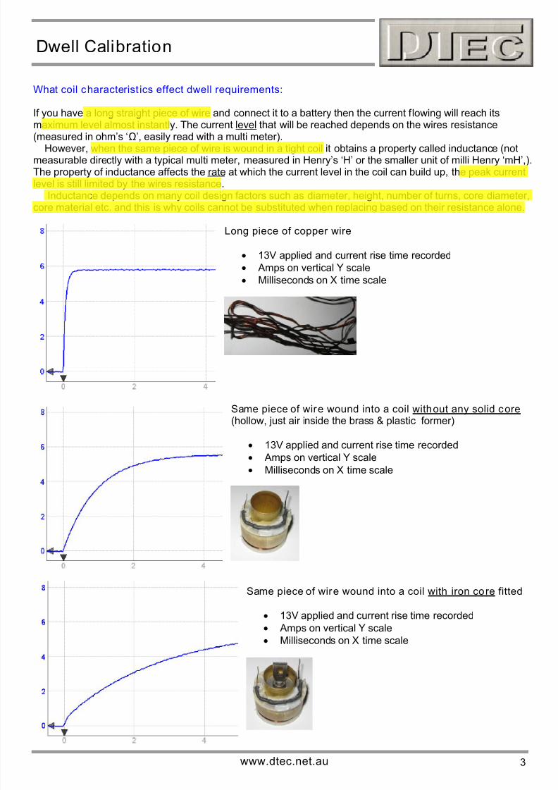
Long piece of copper wire
• 13V applied and current rise time recorded
• Amps on vertical Y scale
• Milliseconds on X time scale
Same piece of wire wound into a coil without any solid core(hollow, just air inside the brass & plastic former)
• 13V applied and current rise time recorded
• Amps on vertical Y scale
• Milliseconds on X time scale
Same piece of wire wound into a coil with iron core fitted
• 13V applied and current rise time recorded
• Amps on vertical Y scale
• Milliseconds on X time scale
www.dtec.net.au 3
7/28/2019 Dwell Calibration
http://slidepdf.com/reader/full/dwell-calibration 4/16
Dwell Calibration
Note how long the coil took to get to a certain current level, like 5 Amps, in each of the above traces, nowpicture if we had to power it up for just the right amount of time to reach this target current level. You can seehow different coils would have very different dwell requirements! Coil inductance has a very large effect anddwell control settings must be measured by trial, especially when all the other variables that will be mentioned
later come into play.
Example of coil wind ing specs,From a common High Energy Ignit ion (HEI) Coil -
Primary resistance 0.4 Ω Primary inductance 3.5 mHSecondary resistance 7.8 KΩ Secondary inductance 23.7 H
Why’s dwell important:
Inductive ignition systems store their energy in a magnetic field and the correct dwell will allow this field toreach its maximum strength within the design limits of the coil.
Design limits exceeded!Power dissipation in the coil exceeds design limits, the plastic bobbinmelts and the epoxy filler brakes down. Expanding material and gassesrupture the casing.
As mentioned, the coil stores energy in a magnetic field and the level of this is dependant on coil current. For anyone actually interested, the energy stored is measured in Joules and is ½ the inductance x the currentsquared. This means a small reduction in current makes a HUGE difference to energy (as it’s squared).
Correct dwell control has a direct effect on current level and therefore energy stored… OK so who cares?Well, have a look at the following pictures that show the effect of coil current on spark appearance andduration. YOU should care!
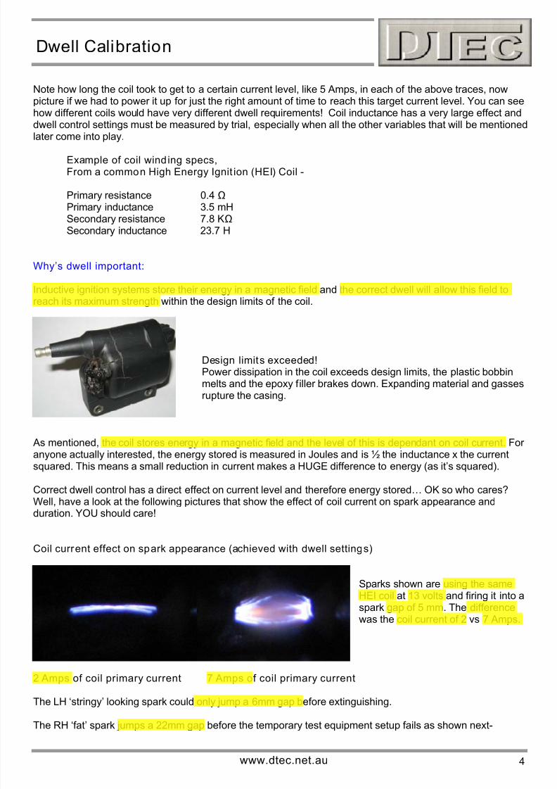
Coil current effect on spark appearance (achieved with dwell settings)
Sparks shown are using the sameHEI coil at 13 volts and firing it into aspark gap of 5 mm. The differencewas the coil current of 2 vs 7 Amps.
2 Amps of coil primary current 7 Amps of coil primary current
The LH ‘stringy’ looking spark could only jump a 6mm gap before extinguishing.
The RH ‘fat’ spark jumps a 22mm gap before the temporary test equipment setup fails as shown next-
www.dtec.net.au 4

7/28/2019 Dwell Calibration
http://slidepdf.com/reader/full/dwell-calibration 5/16
Dwell Calibration
Spectacular, if it’s not your coil!
This coil has more voltage reserve than is required to jump the test gapused so it ‘flashes’ down the HT tower to the primary terminals.
NEVER let this happen, it spells death to ignition components and evenvehicle electronics systems.
Also, NEVER open circuit a HT lead etc when bench testing or on avehicle (perhaps your attempting to knock out a cylinder), the stored coilenergy will dissipate back into the system and damage the switchingelectronics. Besides, many modern coils can generate more open circuitvoltage than their insulation can withstand and they will internally breakdown. What occurs is a carburizing of the potting material leading to aconductive path for future short circuits. When the coil voltage demand ishigh, such as when you accelerate suddenly, the fault can occur.
2 and 4 Amp extremes of current level are used here to clearly show an effect. To achieve these the dwelltime only had to be altered just over 3 milliseconds for this particular coil!
Another way to view the effect of low coil current is to see the effect on an engines spark duration (the timethe spark is ‘firing’ across the spark plugs electrodes). This is a good comparative indication of stored coilenergy. For this demonstration we fired the coil into a fixed spark gap whilst measuring the voltage and time.
Coil current effect on spark duration (achieved with dwell settings)
2 Amps of coil primary current
• Milliseconds on X time scale
• KV on Y voltage scale
Spark duration of only 0.5 ms
7 Amps of coil primary current
• Milliseconds on X time scale
• KV on Y voltage scale
Spark duration of 1.4 ms now
As you’ll read in another Dec article, spark plugs are actually very inefficient at transferring energy to themixture so we need to give them all we can.
www.dtec.net.au 5
7/28/2019 Dwell Calibration
http://slidepdf.com/reader/full/dwell-calibration 6/16
Dwell Calibration
Dwell control methods for Aftermarket ECU’s:
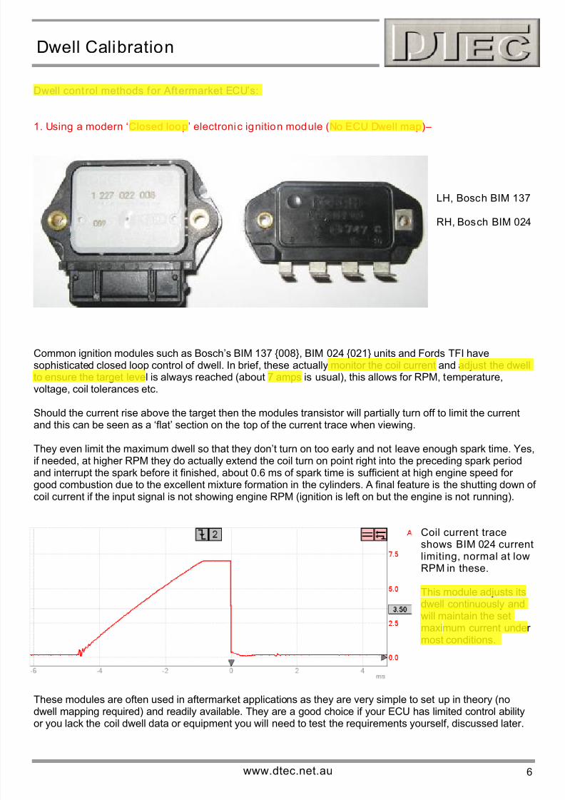
1. Using a modern ‘Closed loop’ electronic ignition module (No ECU Dwell map)–
LH, Bosch BIM 137
RH, Bosch BIM 024
Common ignition modules such as Bosch’s BIM 137 008, BIM 024 021 units and Fords TFI havesophisticated closed loop control of dwell. In brief, these actually monitor the coil current and adjust the dwellto ensure the target level is always reached (about 7 amps is usual), this allows for RPM, temperature,voltage, coil tolerances etc.
Should the current rise above the target then the modules transistor will partially turn off to limit the currentand this can be seen as a ‘flat’ section on the top of the current trace when viewing.
They even limit the maximum dwell so that they don’t turn on too early and not leave enough spark time. Yes,if needed, at higher RPM they do actually extend the coil turn on point right into the preceding spark periodand interrupt the spark before it finished, about 0.6 ms of spark time is sufficient at high engine speed for good combustion due to the excellent mixture formation in the cylinders. A final feature is the shutting down of coil current if the input signal is not showing engine RPM (ignition is left on but the engine is not running).
Coil current traceshows BIM 024 current
limiting, normal at lowRPM in these.
This module adjusts itsdwell continuously andwill maintain the setmaximum current under most conditions.
These modules are often used in aftermarket applications as they are very simple to set up in theory (nodwell mapping required) and readily available. They are a good choice if your ECU has limited control abilityor you lack the coil dwell data or equipment you will need to test the requirements yourself, discussed later.
www.dtec.net.au 6
7/28/2019 Dwell Calibration
http://slidepdf.com/reader/full/dwell-calibration 7/16
Dwell Calibration
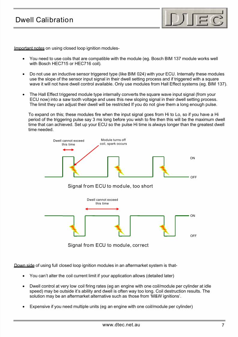
Important notes on using closed loop ignition modules-
• You need to use coils that are compatible with the module (eg. Bosch BIM 137 module works wellwith Bosch HEC715 or HEC716 coil).
• Do not use an inductive sensor triggered type (like BIM 024) with your ECU. Internally these modulesuse the slope of the sensor input signal in their dwell setting process and if triggered with a squarewave it will not have dwell control available. Only use modules from Hall Effect systems (eg. BIM 137).
Module turns off
coil, spark occursDwell cannot exceed
this time
ON
OFF
Signal from ECU to module, too short
Dwell cannot exceedthis time
ON
OFF
Signal from ECU to module, correct
• The Hall Effect triggered module type internally converts the square wave input signal (from your ECU now) into a saw tooth voltage and uses this new sloping signal in their dwell setting process.The limit they can adjust their dwell will be restricted If you do not give them a long enough pulse.
To expand on this; these modules fire when the input signal goes from Hi to Lo, so if you have a Hi
period of the triggering pulse say 3 ms long before you wish to fire then this will be the maximum dwelltime that can achieved. Set up your ECU so the pulse Hi time is always longer than the greatest dwelltime needed.
Down side of using full closed loop ignition modules in an aftermarket system is that-
• You can’t alter the coil current limit if your application allows (detailed later)
• Dwell control at very low coil firing rates (eg an engine with one coil/module per cylinder at idlespeed) may be outside it’s ability and dwell is often way too long. Coil destruction results. The
solution may be an aftermarket alternative such as those from ‘M&W ignitions’.
• Expensive if you need multiple units (eg an engine with one coil/module per cylinder)
www.dtec.net.au 7
7/28/2019 Dwell Calibration
http://slidepdf.com/reader/full/dwell-calibration 8/16
Dwell Calibration
2. Mapped dwell (ECU has actual control of the dwell)-
This is when the ECU sets the dwell based on an internal map. The main variable is battery voltage as this
has a major effect on the time needed to allow a coil to reach our target current level. The map has to beprogrammed correctly for the particular coil used. Nearly all production vehicles now use this method.
NEVER substitute the coil for another type on a mapped system. The ECU will not know you have done thisand will still turn the coil on for a certain time, if your new coil charges quicker (lower inductance) then the coilor ECU will be damaged. If a slower charging coil is fitted (higher inductance) you will get a poor spark.
The ECU controls a switching device (transistor usually) to switch the coil on for the exact time it needs toreach the desired current level before turning it of for the spark. The transistor (known as ‘end stage’ or ‘driver’ also) may be mounted inside ECU, mounted external or even be built into the coils as is common.
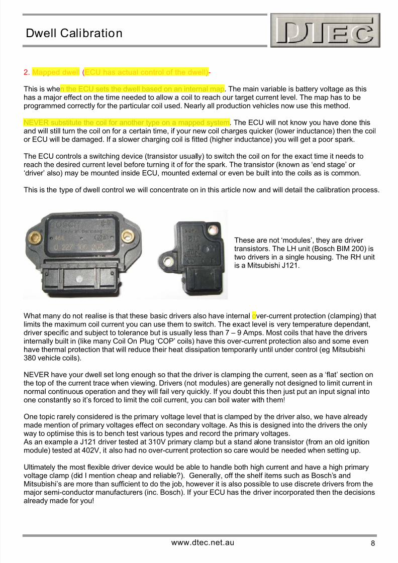
This is the type of dwell control we will concentrate on in this article now and will detail the calibration process.
These are not ‘modules’, they are driver transistors. The LH unit (Bosch BIM 200) istwo drivers in a single housing. The RH unitis a Mitsubishi J121.
What many do not realise is that these basic drivers also have internal over-current protection (clamping) thatlimits the maximum coil current you can use them to switch. The exact level is very temperature dependant,driver specific and subject to tolerance but is usually less than 7 – 9 Amps. Most coils that have the driversinternally built in (like many Coil On Plug ‘COP’ coils) have this over-current protection also and some evenhave thermal protection that will reduce their heat dissipation temporarily until under control (eg Mitsubishi380 vehicle coils).
NEVER have your dwell set long enough so that the driver is clamping the current, seen as a ‘flat’ section onthe top of the current trace when viewing. Drivers (not modules) are generally not designed to limit current in
normal continuous operation and they will fail very quickly. If you doubt this then just put an input signal intoone constantly so it’s forced to limit the coil current, you can boil water with them!
One topic rarely considered is the primary voltage level that is clamped by the driver also, we have alreadymade mention of primary voltages effect on secondary voltage. As this is designed into the drivers the onlyway to optimise this is to bench test various types and record the primary voltages. As an example a J121 driver tested at 310V primary clamp but a stand alone transistor (from an old ignitionmodule) tested at 402V, it also had no over-current protection so care would be needed when setting up.
Ultimately the most flexible driver device would be able to handle both high current and have a high primaryvoltage clamp (did I mention cheap and reliable?). Generally, off the shelf items such as Bosch’s andMitsubishi’s are more than sufficient to do the job, however it is also possible to use discrete drivers from the
major semi-conductor manufacturers (inc. Bosch). If your ECU has the driver incorporated then the decisionsalready made for you!
www.dtec.net.au 8
7/28/2019 Dwell Calibration
http://slidepdf.com/reader/full/dwell-calibration 9/16
Dwell Calibration
Why do we need a dwell ‘map’:
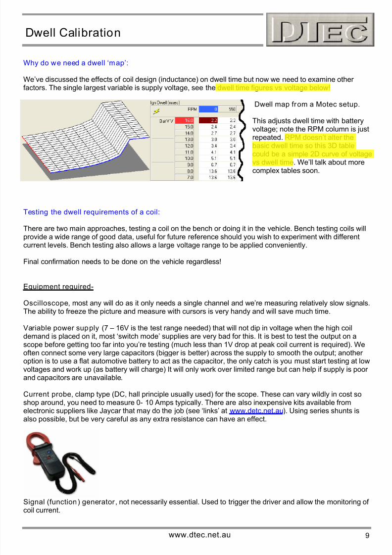
We’ve discussed the effects of coil design (inductance) on dwell time but now we need to examine other factors. The single largest variable is supply voltage, see the dwell time figures vs voltage below!
Dwell map from a Motec setup.
This adjusts dwell time with batteryvoltage; note the RPM column is justrepeated. RPM doesn’t alter thebasic dwell time so this 3D tablecould be a simple 2D curve of voltagevs dwell time. We’ll talk about morecomplex tables soon.
Testing the dwell requirements of a coil:
There are two main approaches, testing a coil on the bench or doing it in the vehicle. Bench testing coils willprovide a wide range of good data, useful for future reference should you wish to experiment with differentcurrent levels. Bench testing also allows a large voltage range to be applied conveniently.
Final confirmation needs to be done on the vehicle regardless!
Equipment required-
Oscilloscope, most any will do as it only needs a single channel and we’re measuring relatively slow signals.The ability to freeze the picture and measure with cursors is very handy and will save much time.
Variable power supply (7 – 16V is the test range needed) that will not dip in voltage when the high coildemand is placed on it, most ‘switch mode’ supplies are very bad for this. It is best to test the output on ascope before getting too far into you’re testing (much less than 1V drop at peak coil current is required). Weoften connect some very large capacitors (bigger is better) across the supply to smooth the output; another option is to use a flat automotive battery to act as the capacitor, the only catch is you must start testing at lowvoltages and work up (as battery will charge) It will only work over limited range but can help if supply is poor and capacitors are unavailable.
Current probe, clamp type (DC, hall principle usually used) for the scope. These can vary wildly in cost soshop around, you need to measure 0- 10 Amps typically. There are also inexpensive kits available fromelectronic suppliers like Jaycar that may do the job (see ‘links’ at www.detc.net.au). Using series shunts isalso possible, but be very careful as any extra resistance can have an effect.
Signal (function) generator , not necessarily essential. Used to trigger the driver and allow the monitoring of coil current.
www.dtec.net.au 9
7/28/2019 Dwell Calibration
http://slidepdf.com/reader/full/dwell-calibration 10/16
Dwell Calibration
Getting the figures on the bench-
The coil to be tested needs to be powered from the variable supply and switched via the driver. A currentprobe and scope are used to monitor the coil current. The driver can be ideally triggered from the signal
generator or even just ‘flashed’ on manually.Most drivers require a certain of current to drive them (20 – 40 mA typically), never apply direct power, at thevery least use an automotive ‘test lamp’, equivalent small wattage globe or a resistor in series with the driversinput terminal to limit the current. If you have basic electronics knowledge you can measure the voltagedropped across the driver and determine that it is fully on.
If you do not turn on the driver fully (too low a drive signal) then the coil current will be limited and the driver will overheat, this can be an issue when setting up your ECU also, many allow you to set the drive current,Motec for example has a 20mA or 40 mA selectable level.
Record the coil current rise time at particular supply voltages and note the time to reach various current levels.This is where the freeze and measure ability of a scope can save lots of time. In theory you could actually
dispense with the scope and use a multimeter with ‘peak hold detection’ but this would require a very carefuluse of a signal generator to adjust the drive signal duration to the correct coil current is reached and thenrecord this signal duration. Chances of failure would be high.
Be very careful testing and only pulse the coil briefly as there may be no protection at all (depending on your driver choice) and thermal dissipation will be high, allow cooling time and check driver for temperature rise.
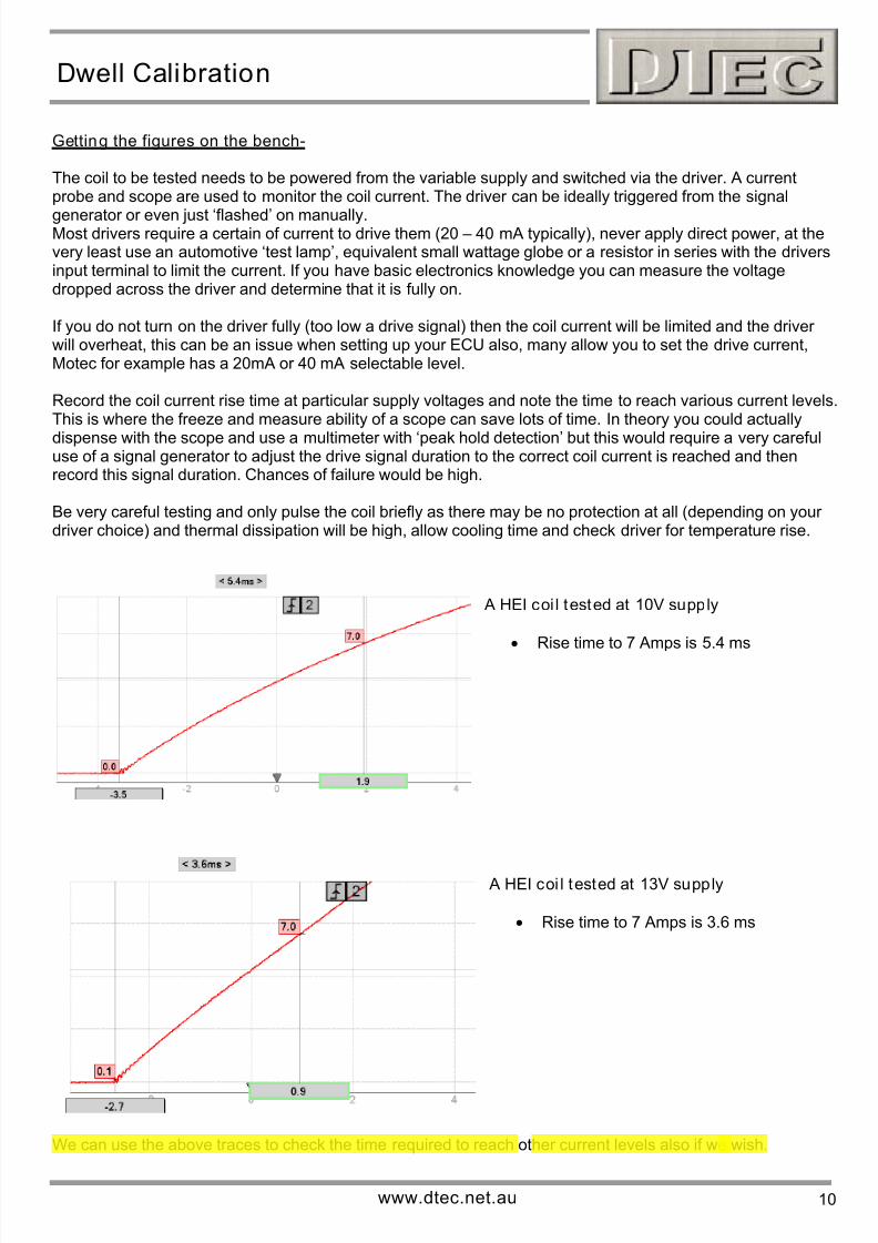
A HEI coi l tested at 10V supply
• Rise time to 7 Amps is 5.4 ms
A HEI coi l tested at 13V supply
• Rise time to 7 Amps is 3.6 ms
We can use the above traces to check the time required to reach other current levels also if we wish.
www.dtec.net.au 10
7/28/2019 Dwell Calibration
http://slidepdf.com/reader/full/dwell-calibration 11/16
Dwell Calibration
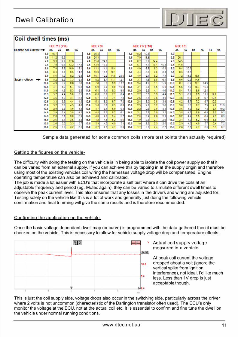
Sample data generated for some common coils (more test points than actually required)
Getting the figures on the vehicle-
The difficulty with doing the testing on the vehicle is in being able to isolate the coil power supply so that itcan be varied from an external supply. If you can achieve this by tapping in at the supply origin and thereforeusing most of the existing vehicles coil wiring the harnesses voltage drop will be compensated. Engine
operating temperature can also be achieved and calibrated.The job is made a lot easier with ECU’s that incorporate a self test where it can drive the coils at anadjustable frequency and period (eg. Motec again), they can be varied to simulate different dwell times toobserve the peak current level. This also ensures that any losses in the drivers and wiring are adjusted for.Testing solely on the vehicle like this is a lot of work and generally just doing the following vehicleconfirmation and final trimming will give the same results and is therefore recommended.
Confirming the application on the vehicle-
Once the basic voltage dependant dwell map (or curve) is programmed with the data gathered then it must bechecked on the vehicle. This is necessary to allow for vehicle supply voltage drop and temperature effects.
Actual coi l supply vol tagemeasured in a vehicle.
At peak coil current the voltagedropped about a volt (ignore thevertical spike from ignitioninterference), not ideal, I’d like muchless. Less than 1V drop is justacceptable though.
This is just the coil supply side, voltage drops also occur in the switching side, particularly across the driver where 2 volts is not uncommon (characteristic of the Darlington transistor often used). The ECU’s onlymonitor the voltage at the ECU, not at the actual coil etc. It is essential to confirm and fine tune the dwell onthe vehicle under normal running conditions.
www.dtec.net.au 11
7/28/2019 Dwell Calibration
http://slidepdf.com/reader/full/dwell-calibration 12/16
Dwell Calibration
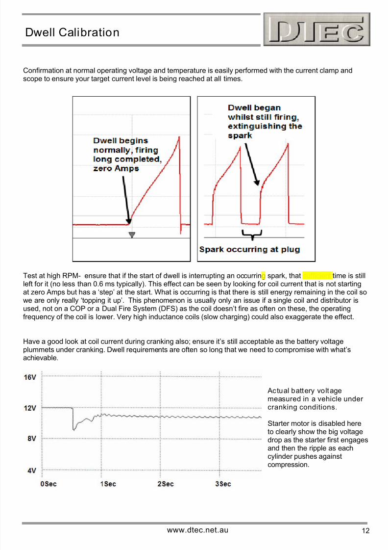
Confirmation at normal operating voltage and temperature is easily performed with the current clamp andscope to ensure your target current level is being reached at all times.
Test at high RPM- ensure that if the start of dwell is interrupting an occurring spark, that sufficient time is stillleft for it (no less than 0.6 ms typically). This effect can be seen by looking for coil current that is not startingat zero Amps but has a ‘step’ at the start. What is occurring is that there is still energy remaining in the coil sowe are only really ‘topping it up’. This phenomenon is usually only an issue if a single coil and distributor isused, not on a COP or a Dual Fire System (DFS) as the coil doesn’t fire as often on these, the operatingfrequency of the coil is lower. Very high inductance coils (slow charging) could also exaggerate the effect.
Have a good look at coil current during cranking also; ensure it’s still acceptable as the battery voltageplummets under cranking. Dwell requirements are often so long that we need to compromise with what’sachievable.
Actual battery voltagemeasured in a vehicle under cranking conditions.
Starter motor is disabled hereto clearly show the big voltagedrop as the starter first engagesand then the ripple as eachcylinder pushes againstcompression.
www.dtec.net.au 12
7/28/2019 Dwell Calibration
http://slidepdf.com/reader/full/dwell-calibration 13/16
Dwell Calibration
Selecting the coil current level to use:
The only way to guarantee reliable service is to set the coil primary current to the same level that is used in
the vehicles the components are used on. Vehicle and component manufacturers do many severe tests tocheck reliability. If you use aftermarket or cheap replacement coils then you’re on your own!
There are gains to be had by raising the coil current slightly but long term component endurance will be agamble. Manufacturers have to be conservative for a reliability margin and to allow for manufacturingtolerances, they really know their limits. We have tested some COP systems that run reliably with 12 Amps(Toyota)
However, the coil selected may now be used in an aftermarket application that gives greater time betweensparks than it was designed for, like a distributor system coil used in a COP or DFS system, this allows thecoil to cool down between firings. Unfortunately, in any system the higher the engine RPM, the greater thetemperature build up, as there is less time without current flow to cool down.
Another thermal consideration is for example, the mounting location; this may increase the componentstemperature as in when mounted directly on the engine above each cylinder. Temperatures can easily reach80ºC under the bonnet.
Higher coil current flow will increase the resistive losses in the coil by a squared function (I²R), so a smallincrease in resistance for a given current passing will have much larger effect on the power losses andtherefore heat dissipation.
Temperature will increase the resistance of the coil and wiring, ‘0.393 % per ºC’ is copper’s temperaturecharacteristics so at 100 ºC its 39% higher, drivers actually have lower losses at higher temperature (semi-conductor materials used) and so help cancel out some of the temperature effect on losses.
Operating temperature conditions can be checked at other voltages, besides those normally uncounted, byrunning with the alternator disabled and headlights etc. on to reduce the battery voltage gradually.
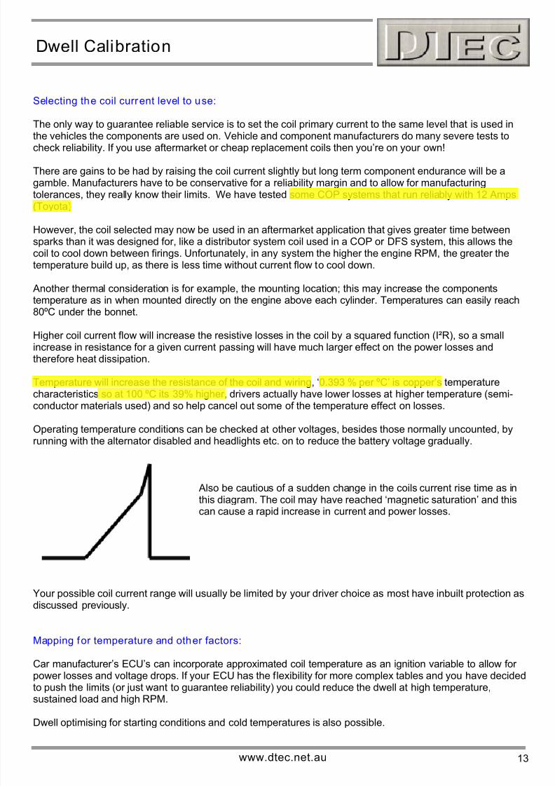
Also be cautious of a sudden change in the coils current rise time as inthis diagram. The coil may have reached ‘magnetic saturation’ and thiscan cause a rapid increase in current and power losses.
Your possible coil current range will usually be limited by your driver choice as most have inbuilt protection asdiscussed previously.
Mapping for temperature and other factors:
Car manufacturer’s ECU’s can incorporate approximated coil temperature as an ignition variable to allow for power losses and voltage drops. If your ECU has the flexibility for more complex tables and you have decided
to push the limits (or just want to guarantee reliability) you could reduce the dwell at high temperature,sustained load and high RPM.
Dwell optimising for starting conditions and cold temperatures is also possible.
www.dtec.net.au 13
7/28/2019 Dwell Calibration
http://slidepdf.com/reader/full/dwell-calibration 14/16
Dwell Calibration
Maximum RPM before current will drop off , based on dwell:
When the dwell time to reach a certain current level is known, we can work out how many RPM could bereached before the coil current will be reduced from our target due to lack of available charging time. We can
do this for any number of cylinders the coil must fire. The table below is based on the earlier dwell figures.
The formula used, I suggest you put in an Excel spreadsheet -
(1000 / (Dwell time + min burn time)) x 120, divide this by number of cylinders supported by the coil.
Dwell time = time to reach your target current in msMin burn time = min time left for the spark to occur, 0.6 ms is suggested
NEVER use a BIM 024 module as a driver transistor :
It is not uncommon to see BIM 024 modules used as driver transistors in aftermarket systems, particularlymulti coil applications as it’s a cost effective module.NEVER do this, it is a full ‘closed loop’ module that’s expecting to be triggered by a sinusoidal shaped input(AC voltage) from a distributor mounted sensor, not from a square wave out of an ECU. Please re-read the
previous section on closed loop module operation if this is not clear!
When it’s used incorrectly strange things can happen at certain RPM and input pulse widths, there is alsogenerally excessive current limiting periods and therefore heat build up. The result could be poor and difficultto diagnose ignition performance or component failure.
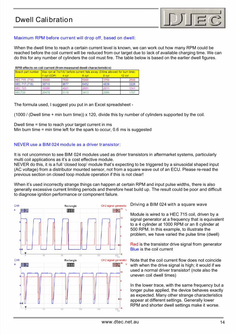
Driving a BIM 024 with a square wave
Module is wired to a HEC 715 coil, driven by asignal generator at a frequency that is equivalentto a 4 cylinder at 1000 RPM or an 8 cylinder at500 RPM. In this example, to illustrate the
problem, we have varied the pulse time (dwell)
Red is the transistor drive signal from generator Blue is the coil current
Note that the coil current flow does not coincidewith when the drive signal is high; it would if weused a normal driver transistor! (note also theuneven coil dwell times)
In the lower trace, with the same frequency but alonger pulse applied, the device behaves exactlyas expected. Many other strange characteristicsappear at different settings. Generally lower RPM and shorter dwell settings make it worse.
www.dtec.net.au 14
7/28/2019 Dwell Calibration
http://slidepdf.com/reader/full/dwell-calibration 15/16
Dwell Calibration
Disclaimer: You have been WARNED!
Before you race out and start testing read the whole article and if you are unsure about anything then seek
further help before continuing. Due to the DIY nature of this article and variations from system to system theremay be some challenges you have to overcome and further research required.The article is a guide - not a guarantee! DTec accepts no responsibility should you decide to undertakeany modification - it’s entirely at your own risk.Be aware also that automotive equipment manufacturers will not give warranty if their components are usedin the incorrect, un-specified application, nor should they!
Please keep an eye out for further DTec articles at www.dtec.net.au and visit our links page for references tofurther information.
Appendix
Dwell control methods background:
The following “points systems” information and dwell extension methods only gives enthusiasts someinteresting background insight; please don’t get ‘bogged down’ in it.
Points systems (also called contact or Kettering)-
The earlier ignitions had a fixed dwell, these were mechanical ‘points’ systems. The dwell is set by therelationship of the contact points to the rotating distributor cam and does not vary. The limiting factor is howfast we can reliably open (for a spark) and then close the points to let the coil primary current build up again,
points ‘bounce’ and durability are issues.
What’s happening is the points are closed for a certain number of degrees of distributor rotation but the coilneeds a certain amount of time, not cam angle. At high speed the same degrees of cam angle pass in ashorter time.The result is that at high RPM, the coil cannot be turned on long enough (dwell too short) to reach full currentand ignition performance falls off. All this and we haven’t even mentioned the lack of voltage compensation!
Performance is made worse by another limiting factor, points can only switch a small amount of currentreliably (generally 4-5 Amps) and coils for these systems have a high inductance and therefore take a longtime to charge up. This is due to coil resistance needing to be high (therefore lots of wire turns) to limit thecurrent and protect the points, the later addition of a ‘ballast’ resistor in systems was to externally limit the
current and free up the coil designer to use lower inductance coils. Bypassing the ballast to boostperformance when cranking (low battery voltage) was a later addition!
www.dtec.net.au 15
7/28/2019 Dwell Calibration
http://slidepdf.com/reader/full/dwell-calibration 16/16
Dwell Calibration
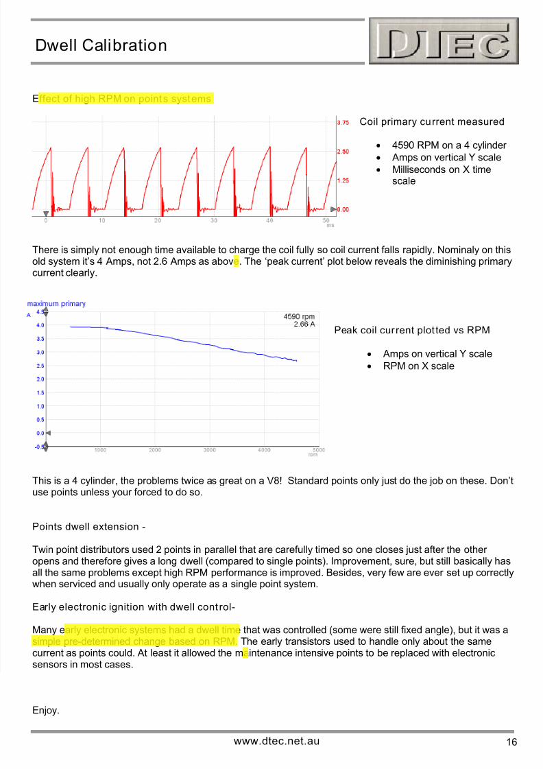
Effect of high RPM on points systems
Coil primary current measured
• 4590 RPM on a 4 cylinder
• Amps on vertical Y scale
• Milliseconds on X timescale
There is simply not enough time available to charge the coil fully so coil current falls rapidly. Nominaly on thisold system it’s 4 Amps, not 2.6 Amps as above. The ‘peak current’ plot below reveals the diminishing primary
current clearly.
Peak coil current plot ted vs RPM
• Amps on vertical Y scale
• RPM on X scale
This is a 4 cylinder, the problems twice as great on a V8! Standard points only just do the job on these. Don’tuse points unless your forced to do so.
Points dwell extension -
Twin point distributors used 2 points in parallel that are carefully timed so one closes just after the other opens and therefore gives a long dwell (compared to single points). Improvement, sure, but still basically hasall the same problems except high RPM performance is improved. Besides, very few are ever set up correctlywhen serviced and usually only operate as a single point system.
Early electronic ignition with dwell cont rol-
Many early electronic systems had a dwell time that was controlled (some were still fixed angle), but it was asimple pre-determined change based on RPM. The early transistors used to handle only about the samecurrent as points could. At least it allowed the maintenance intensive points to be replaced with electronicsensors in most cases.
Enjoy.