Embed Size (px)
Citation preview
8/2/2019 DWLN251 Lab3
http://slidepdf.com/reader/full/dwln251-lab3 1/5
School of Engineering
DWLN251 Wireless LANs
Lab 3: Configuring HREAP
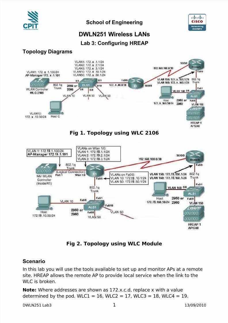
Topology Diagrams
Fig 1. Topology using WLC 2106
Fig 2. Topology using WLC Module
Scenario
In this lab you will use the tools available to set up and monitor APs at a remote
site. HREAP allows the remote AP to provide local service when the link to the
WLC is broken.Note: Where addresses are shown as 172.x.c.d, replace x with a value
determined by the pod. WLC1 = 16, WLC2 = 17, WLC3 = 18, WLC4 = 19.
DWLN251 Lab3 1 13/09/2010
8/2/2019 DWLN251 Lab3
http://slidepdf.com/reader/full/dwln251-lab3 2/5
Step 1
Set up the topology as shown. The main section should be configured the same
as Labs 1 and 2.
Step 2a – For Standalone WLC
Add router R1 and set up a layer 3 link between the router and the switch using
172.x.40.0/24.
For the serial interface, use 192.168.100.0/30. On the DCE end of this link, set
the clock rate to 1Mb/s.
Configure EIGRP routing on the switch and router. Do not include VLAN50 in the
network range. All VLANs should be passive interfaces.
Step 2b – For WLC Module
Use a serial interface on the router, and use 192.168.100.0/30 on this to a
second router. On the DCE end of this link, set the clock rate to 1Mb/s.
Configure EIGRP routing on this router. Do not include VLAN50 in the network
range. All VLANs should be passive interfaces.
Step 3 – Configure the Branch Router
Configure the serial link to operate correctly with the main router as per step 2.
Set up a trunk to the switch with two VLANs, 150 and 160, using 172.x.150.0/24
and 172.x.160.0/24. The router subinterfaces should use .1 addresses.Set up two dhcp pools for VLAN 150 and 160. Add option 43 and 60 to VLAN 150,
using the AP Manager address (172.x.1.101) as the option 43 information.
Set up EIGRP routing, making the Ethernet interfaces passive.
Step 4 – Configure the Branch Switch
Set hostname, login names and passwords.
Configure the interface to the router as a trunk.Configure the interface for the AP as a trunk.
interface fa0/8
description the Access Point port
switchport trunk encap dot1q
switchport trunk native vlan 150
switchport trunk allowed vlan 150, 160
switchport mode trunk
spanning-tree portfast
Set up a port for the PC on VLAN 160
Step 5 – Setup the AP
Log on to the WLC using a web browser.DWLN251 Lab3 2 13/09/2010
8/2/2019 DWLN251 Lab3
http://slidepdf.com/reader/full/dwln251-lab3 3/5
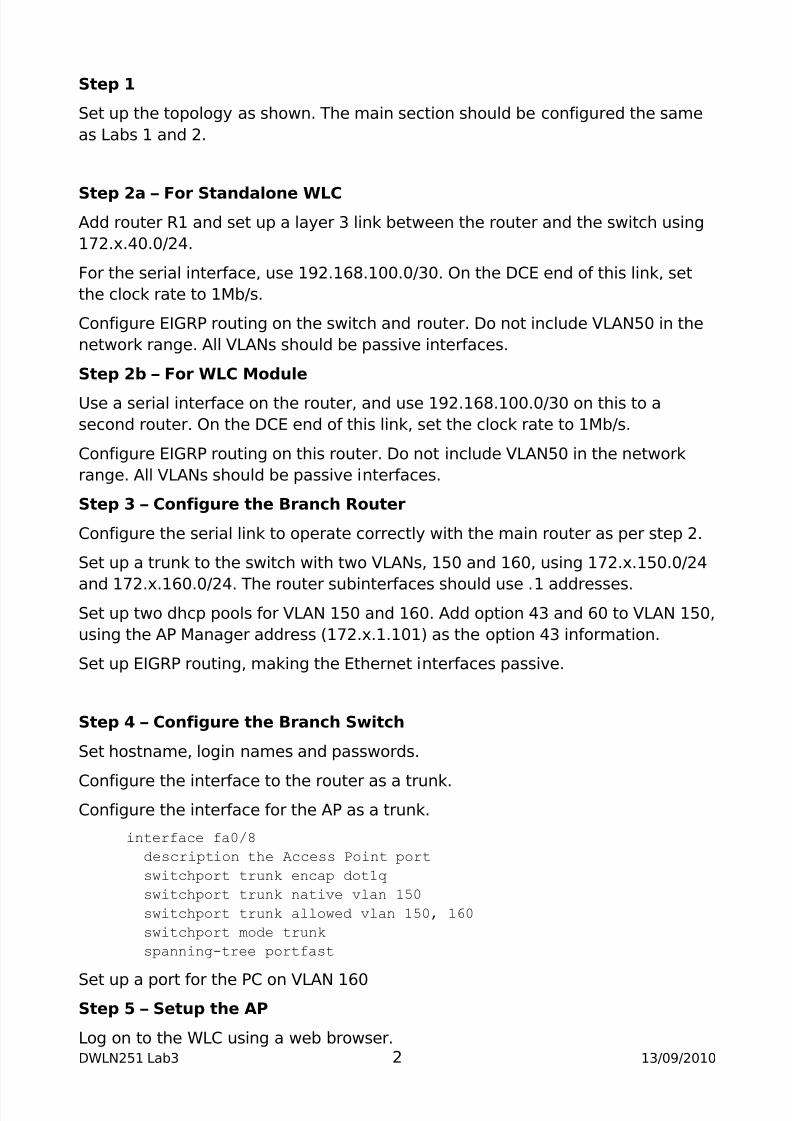
Select WIRELESS > All APs and select the AP to be set up as HREAP.
Set the AP Name and location and change the AP mode to H-REAP.
Apply the changes using the Apply button.
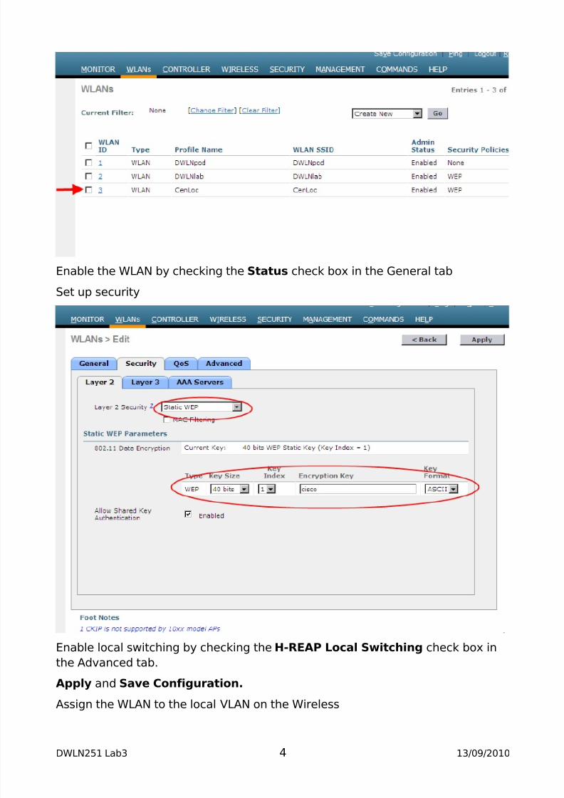
Step 6 – Create and Setup the WLAN
Create the WLAN
DWLN251 Lab3 3 13/09/2010
8/2/2019 DWLN251 Lab3
http://slidepdf.com/reader/full/dwln251-lab3 4/5
Enable the WLAN by checking the Status check box in the General tab
Set up security
Enable local switching by checking the H-REAP Local Switching check box in
the Advanced tab.
Apply and Save Configuration.
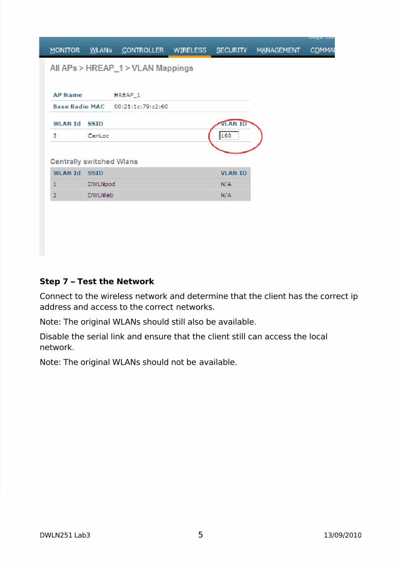
Assign the WLAN to the local VLAN on the Wireless
DWLN251 Lab3 4 13/09/2010
8/2/2019 DWLN251 Lab3
http://slidepdf.com/reader/full/dwln251-lab3 5/5
Step 7 – Test the Network
Connect to the wireless network and determine that the client has the correct ipaddress and access to the correct networks.
Note: The original WLANs should still also be available.
Disable the serial link and ensure that the client still can access the local
network.
Note: The original WLANs should not be available.
DWLN251 Lab3 5 13/09/2010