Embed Size (px)
Citation preview
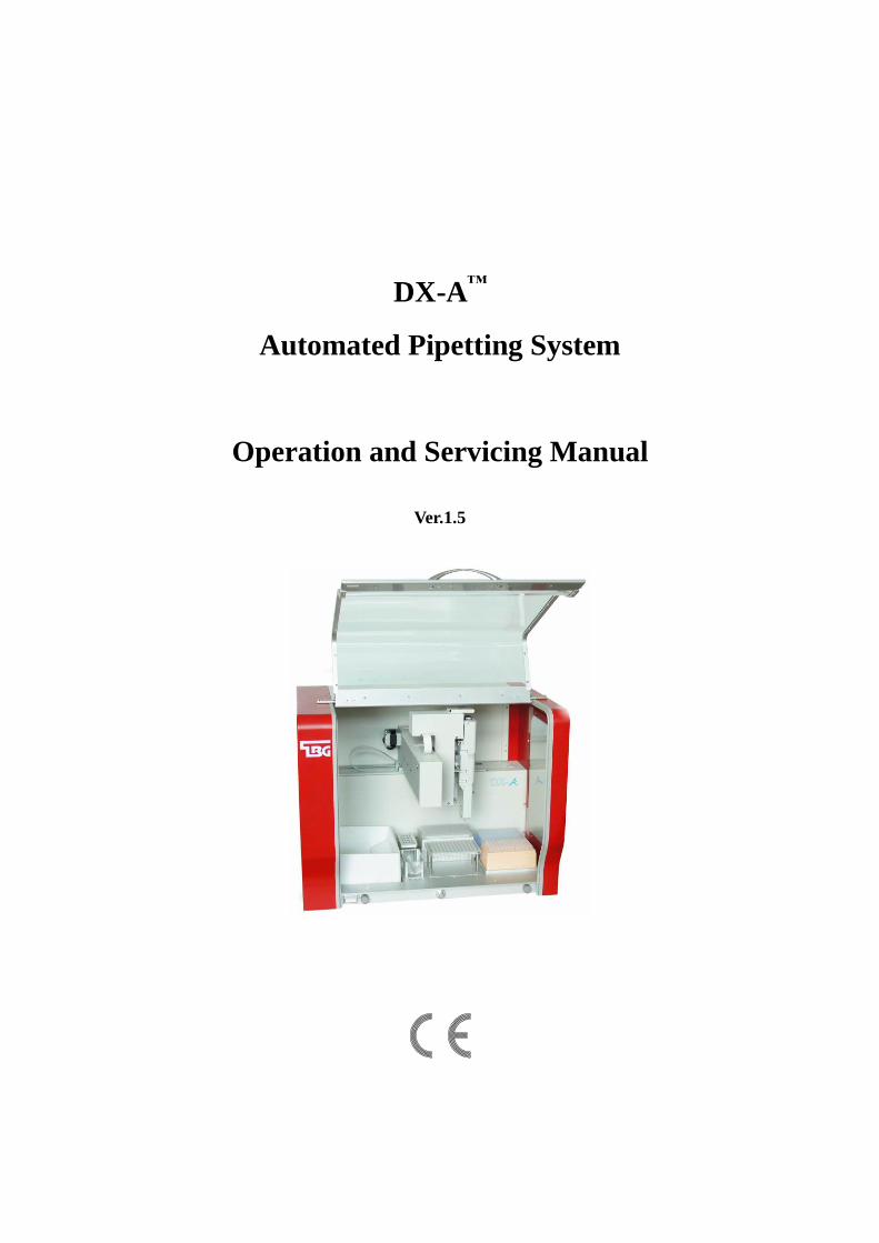
DX-A™
Automated Pipetting System
Operation and Servicing Manual
Ver.1.5
Trademarks:
Beckman®, Biomek
® 3000 ( Beckman Coulter Inc.); Roche
®, LightCycler
® 480 ( Roche
Group); DyNAmo™ ( Finnzyme Oy); SYBR
® (Molecular Probes Inc.); Invitrogen™,
Platinum® ( Invitrogen Corp.), MicroAmp
® ( Applied Biosystems); Microsoft
® ,
Windows® 7 (Microsoft Corp.). All other trademarks are the sole property of their
respective owners.
Copyright Notice:
No part of this manual may be reproduced or transmitted in any form or by any means,
electronic or mechanical, for any purpose, without prior written permission of TBG
Biotechnology Corp.
Table of Contents
1 Safety Precautions ............................................................................... 1
2 Product Introduction ........................................................................... 3
2.1 Features .................................................................................................................... 3
2.2 Hardware Overview ................................................................................................. 4
2.2.1 Outlook ........................................................................................................ 4
2.2.2 Control Net PC ............................................................................................. 6
2.2.3 Automated Pipetting Module (APM) ........................................................... 7
2.2.4 Labware Adapters ........................................................................................ 7
2.2.5 Disposable Used Tip Tray .......................................................................... 10
2.3 Software Overview ................................................................................................ 10
3 Getting Started ................................................................................... 11
3.1 Unpacking .............................................................................................................. 11
3.2 Content List ............................................................................................................ 13
3.3 Instrument Installation ........................................................................................... 14
3.3.1 APM Installation and Removal .................................................................. 14
3.3.2 Adapters Installation .................................................................................. 15
3.3.3 Disposable Used Tip Tray Installation ....................................................... 15
3.3.4 Computer Connection ................................................................................ 16
3.4 Power On the Instrument ....................................................................................... 17
3.5 Starting APS ........................................................................................................... 18
3.6 Exiting and Shutting down ..................................................................................... 18
4 Software .............................................................................................. 19
4.1 Menu Map of APS ................................................................................................. 19
4.2 File ......................................................................................................................... 20
4.3 Edit ......................................................................................................................... 21
4.4 Protocol .................................................................................................................. 22
4.5 Labware .................................................................................................................. 23
4.5.1 Enable the Tubes in worktable ................................................................... 23
4.5.2 Enable the Plates in worktable ................................................................... 24
4.5.3 Enable the Tips in worktable ...................................................................... 24
4.6 Report ..................................................................................................................... 24
4.6.1 Protocol Report .......................................................................................... 24
4.6.2 Log Report ................................................................................................. 25
4.7 System .................................................................................................................... 27
4.7.1 Buzzer ........................................................................................................ 27
4.7.2 COM .......................................................................................................... 27
4.7.3 APS Connection ......................................................................................... 28
4.7.4 Robot Test .................................................................................................. 28
4.7.5 Account ...................................................................................................... 31
4.7.6 Software ..................................................................................................... 31
4.7.7 Maintenance Aphorism .............................................................................. 33
4.8 Help ........................................................................................................................ 34
4.8.1 How Do I.................................................................................................... 34
4.8.2 About.......................................................................................................... 34
5 Work Tab Overview ........................................................................... 35
5.1 Icons in the Work Tab for DX-A ........................................................................... 35
5.2 Worktable ............................................................................................................... 36
5.3 Protocol List ........................................................................................................... 37
5.4 Pre-Run and Run .................................................................................................... 37
5.5 Properties ............................................................................................................... 37
6 Operation ............................................................................................ 39
6.1 Create A New Protocol........................................................................................... 39
6.2 Selecting the Labwares .......................................................................................... 40
6.2.1 Reagent Area (R1 and R2) ......................................................................... 40
6.2.2 Removing labwares from Reagent Area (R1 and R2) ............................... 41
6.2.3 Worktable Area (A/B/C) ............................................................................ 42
6.2.4 Worktable Area (D) ................................................................................... 44
6.3 Editing the Protocol ............................................................................................... 44
6.3.1 Adding a command .................................................................................... 45
6.3.2 Removing commands from the procedure ................................................. 45
6.3.3 Duplicating a command ............................................................................. 46
6.3.4 Inserting a command .................................................................................. 47
6.3.5 Exchanging a command ............................................................................. 48
6.3.6 Resetting source and destination of a command ........................................ 49
6.4 Command Overview .............................................................................................. 51
6.4.1 Liquid Transfer (LT) .................................................................................. 52
6.4.2 Multi-Dispense (MD)................................................................................. 54
6.4.3 Serial Dilution (SD) ................................................................................... 58
6.4.4 Mix ............................................................................................................. 62
6.4.5 Hold............................................................................................................ 64
6.4.6 Loop ........................................................................................................... 65
6.5 Command Options ................................................................................................. 68
6.5.1 Liquid Transfer (LT) Option ...................................................................... 68
6.5.2 Multi-Dispense (MD) Option .................................................................... 72
6.5.3 Serial Dilution (SD) ................................................................................... 72
6.5.4 Mix Option ................................................................................................. 75
6.6 Run and Pre-run ..................................................................................................... 76
6.6.1 Pre-run a protocol. ..................................................................................... 76
6.6.2 Run a protocol ............................................................................................ 77
7 Maintenance ....................................................................................... 79
7.1 Cleaning the Worktable .......................................................................................... 79
7.2 Cleaning the Automated Pipetting Module (APM) ............................................... 79
7.3 Servicing the Automated Pipetting Module (APM) ............................................... 79
7.4 Cleaning the Adapters ............................................................................................ 80
7.5 Replacing a Fuse .................................................................................................... 80
8 Troubleshooting ................................................................................. 81
8.1 Error Messages ....................................................................................................... 81
Appendix A : Recommended Consumables ............................................... 82
Appendix B : Technical specifications ........................................................ 85
Appendix C : DX-A Sample Protocols ....................................................... 87
Appendix D : CE Declaration ..................................................................... 88
Appendix E : APS Installation and Uninstallation ................................... 89

1 Safety Precautions
1
1 Safety Precautions
1. It is recommended to carefully read this operating manual prior to operating the
DX-A Automated Pipetting System. To ensure safe operation and avoid problems
that might arise while using the DX-A Automated Pipetting System, it is essential
to observe the following points. Do not use the machine in a potentially explosive
environment or with potentially explosive chemicals.
2. Install the machine in location free of excessive dust.
3. Avoid placing the machine in direct sunlight.
4. Place the machine on a flat and sturdy surface, capable of withstanding the
weight.
5. The machine should be in an indoor temperature of 15 ~ 30C, relative humidity
40 ~85%.
6. Keep the side and rear of the machine at least 10cm from the wall or other
machine.
7. Make sure the power source conforms to the required power supply specifications.
8. To avoid electric shock, make sure the machine is plugged into a grounded
electrical outlet.
9. Do not allow water or any foreign objects in the various openings of the machine.
10. Switch off the machine prior to cleaning or performing service on the machine,
such as replacing the fuses.
11. Repairs should be carried out by authorized service personnel only.
12. Open the lid only when the XYZ axes is not moving.
13. Read and understand the Material Safety Data Sheets (MSDSs) provided by the
manufacturers of the biological and chemical substances before you use and
dispose.
14. For research use only. When using the machine in diagnostic procedures with an
in vitro diagnostic medical device, the IVD Directive should be applied
separately.
15. Users should be informed on the correct usage and user protection measures when
handling hazardous substances. Use protective gloves when handling infectious
substances (such as human samples or reagents)..
16. It is recommended to wear a mask and goggle to prevent users from inhaling
hazardous vapors from the machine.
17. Follow the manufacturers safety instructions when operating the machine.

DX-A™ Automated Pipetting System
2
Pinching Hand Warning Label: Please be aware of pinching hands.
Electric Shock Warning: Please be aware of electric shock.
Warning: Please be aware of the dangers.
2 Product Introduction
3
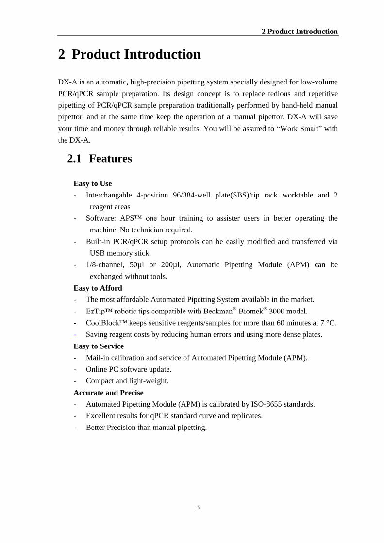
2 Product Introduction
DX-A is an automatic, high-precision pipetting system specially designed for low-volume
PCR/qPCR sample preparation. Its design concept is to replace tedious and repetitive
pipetting of PCR/qPCR sample preparation traditionally performed by hand-held manual
pipettor, and at the same time keep the operation of a manual pipettor. DX-A will save
your time and money through reliable results. You will be assured to “Work Smart” with
the DX-A.
2.1 Features
Easy to Use
- Interchangable 4-position 96/384-well plate(SBS)/tip rack worktable and 2
reagent areas
- Software: APS™ one hour training to assister users in better operating the
machine. No technician required.
- Built-in PCR/qPCR setup protocols can be easily modified and transferred via
USB memory stick.
- 1/8-channel, 50µl or 200µl, Automatic Pipetting Module (APM) can be
exchanged without tools.
Easy to Afford
- The most affordable Automated Pipetting System available in the market.
- EzTip™ robotic tips compatible with Beckman® Biomek
® 3000 model.
- CoolBlock™ keeps sensitive reagents/samples for more than 60 minutes at 7 °C.
- Saving reagent costs by reducing human errors and using more dense plates.
Easy to Service
- Mail-in calibration and service of Automated Pipetting Module (APM).
- Online PC software update.
- Compact and light-weight.
Accurate and Precise
- Automated Pipetting Module (APM) is calibrated by ISO-8655 standards.
- Excellent results for qPCR standard curve and replicates.
- Better Precision than manual pipetting.
DX-A™ Automated Pipetting System
4
2.2 Hardware Overview
The DX-A Automated Pipetting System includes a base platform (“APS”), an
Automated Pipetting Module (APM), a control Notebook computer and other
adapters for labwares. The base platform (APS) is composed of the X/Y/Z axes
motion mechanism, a power supply and some control circuit boards(PCBs) which
are in charge of motion control, communication and APM control. More information
is described below.
2.2.1 Outlook
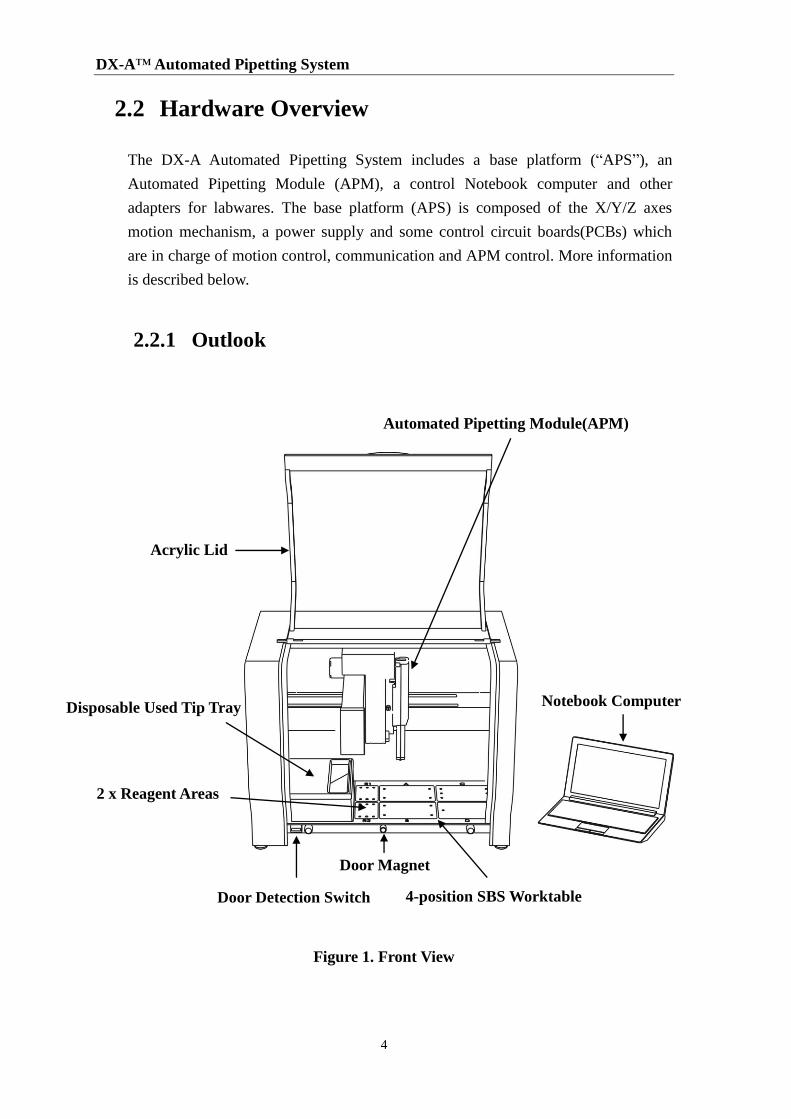
Figure 1. Front View
2 x Reagent Areas
Automated Pipetting Module(APM)
Acrylic Lid
Disposable Used Tip Tray
Door Detection Switch 4-position SBS Worktable
Door Magnet
Notebook Computer
2 Product Introduction
5
Note:
SBS represents the Society for Biomolecular Screening (SBS). The SBS worktable and
its adapters accommodate the SBS recommended labwares.
Name Function
Automated
Pipetting
Module(APM)
APM is the core engine for accurate and precise pipetting. APM can
be exchanged without tools. All APMs are calibrated using ISO-8655
standards. The specifications of APM are shown in section 2.2.3.
Acrylic Lid Used for the protection of dust and emergency stop. The movement of
XYZ axis will stop, once the Acrylic Lid is open. To ensure the Door
Detection Switch is activated, close the front acrylic door to the door
magnet and shut it tightly.
2 x Reagent
Areas
R1 Area: accommodates the adapter for 2 x 4 2ml/1.5ml micro tubes.
R2 Area: accommodates the adapter for 6 x 2ml free standing tubes
and 1 x 5ml bottle.
CoolBlock™ adapters are available for Regent Areas.
4-position SBS
Worktable
A/B/C Area: accommodates the levitated adapters for PCR
plates/stripes.
C/D Area: accommodates the tip racks.
Disposable Used
Tip Tray
Capacity > 300 tips
Door Magnet Lock the acrylic Lid into its place.
Door Detection
Switch
The operation of XYZ axis will stop, once the door opening is
detected.
Notebook
Computer
Used in running the control software: APS. Microsoft® Windows
® 7
operating system or higher version is included.
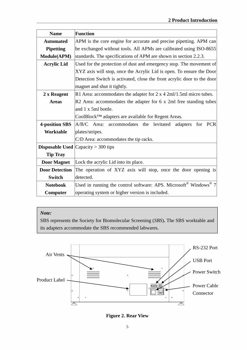
Figure 2. Rear View
RS-232 Port
USB Port
Power Cable
Connector
Power Switch
Air Vents
Product Label
DX-A™ Automated Pipetting System
6
Note:
To avoid any computer virus or software conflict, it is highly recommended
not to connect the Notebook Computer with Internet and not to install any
application software in this Notebook Computer.
The calibration information of XYZ axes and labware adapters is stored in the
APS control software. To switch the Notebook Computer between different
DX-A units will lose the original calibration information and affect the
positioning of adapters.
Name Function
Power Cable
Connector
Power cable socket and fuse drawer.
Power Switch Power On/Off switch. I: ON, O: Off.
USB Port For connection with Notebook Computer.
RS-232 Port For connection with computers that do not have USB ports.
Air Vents For air ventilation.
Product Label Indicates the model name, serial number, power specification, and
other important information
2.2.2 Control Net PC
DX-A is controlled by a Notebook Computer. The specifications of the Notebook
Computer can be upgraded to a higher performance model in the future. For
detailed specifications and operation of the Notebook Computer., please read its
User Guide, Quick Guide and product label carefully. The Microsoft® operation
software English Windows® 7 (or other higher version) and DX-A control
software: APS is pre-installed in the Notebook Computer.
The methods and log files of APS can be transferred easily by an USB storage
device, such as a memory stick and hard drive, or multi-card reader that accepts
Secure Digital (SD), MultiMediaCard (MMC), and Memory Stick (MS).
Minimal PC specifications required to run APS are as followed:
1 gigahertz (GHz) or faster 32/64-bit (x86) processor
1 gigabyte (GB) RAM (32/64-bit)
16 GB available hard disk space (32/64-bit)
DirectX 9 graphics device with WDDM 1.0 or higher driver
2 Product Introduction
7
Indication Light
Fixation Bracket
Tip Fitting
Volume Engrave
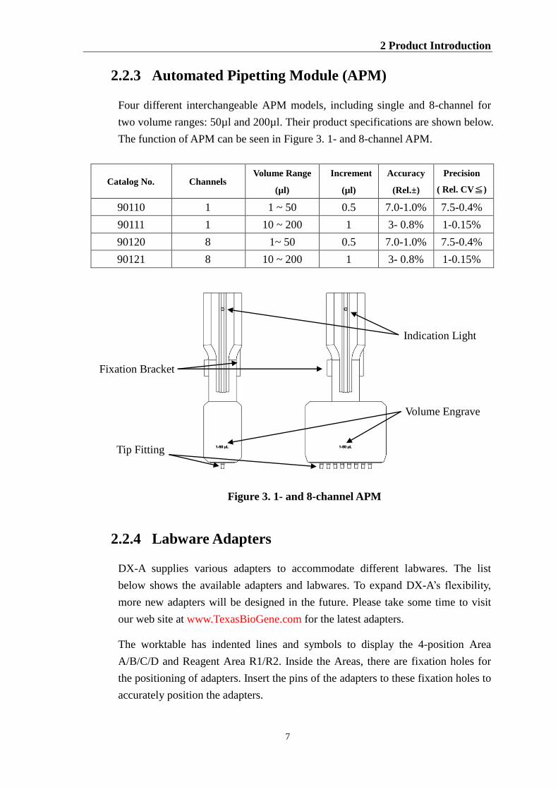
2.2.3 Automated Pipetting Module (APM)
Four different interchangeable APM models, including single and 8-channel for
two volume ranges: 50µl and 200µl. Their product specifications are shown below.
The function of APM can be seen in Figure 3. 1- and 8-channel APM.
Catalog No. Channels Volume Range
(µl)
Increment
(µl)
Accuracy
(Rel.±)
Precision
( Rel. CV≦)
90110 1 1 ~ 50 0.5 7.0-1.0% 7.5-0.4%
90111 1 10 ~ 200 1 3- 0.8% 1-0.15%
90120 8 1~ 50 0.5 7.0-1.0% 7.5-0.4%
90121 8 10 ~ 200 1 3- 0.8% 1-0.15%
Figure 3. 1- and 8-channel APM
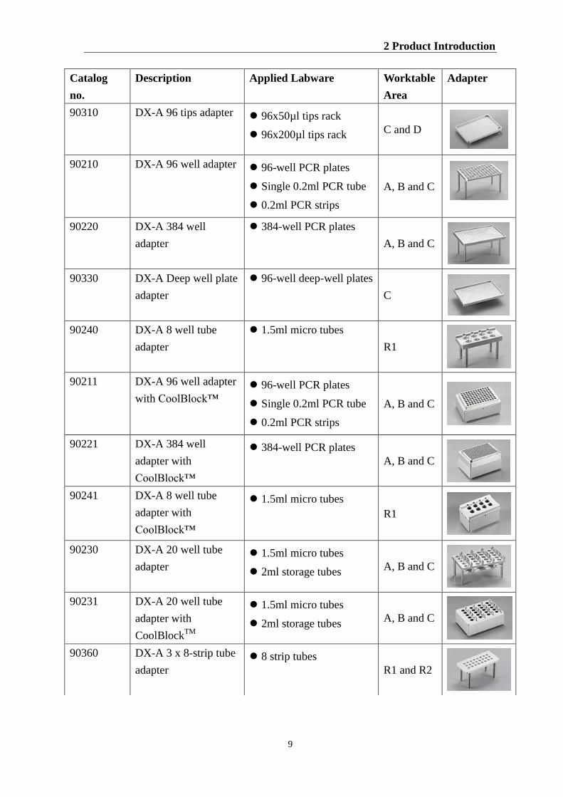
2.2.4 Labware Adapters
DX-A supplies various adapters to accommodate different labwares. The list
below shows the available adapters and labwares. To expand DX-A’s flexibility,
more new adapters will be designed in the future. Please take some time to visit
our web site at www.TexasBioGene.com for the latest adapters.
The worktable has indented lines and symbols to display the 4-position Area
A/B/C/D and Reagent Area R1/R2. Inside the Areas, there are fixation holes for
the positioning of adapters. Insert the pins of the adapters to these fixation holes to
accurately position the adapters.
DX-A™ Automated Pipetting System
8
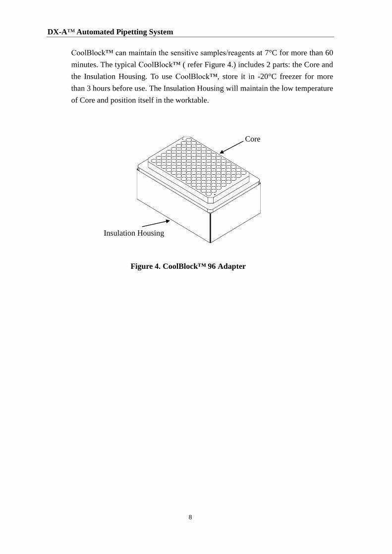
CoolBlock™ can maintain the sensitive samples/reagents at 7°C for more than 60
minutes. The typical CoolBlock™ ( refer Figure 4.) includes 2 parts: the Core and
the Insulation Housing. To use CoolBlock™, store it in -20°C freezer for more
than 3 hours before use. The Insulation Housing will maintain the low temperature
of Core and position itself in the worktable.
Figure 4. CoolBlock™ 96 Adapter
Insulation Housing
Core
2 Product Introduction
9
Catalog
no.
Description Applied Labware Worktable
Area
Adapter
90310 DX-A 96 tips adapter 96x50µl tips rack
96x200µl tips rack C and D
90210 DX-A 96 well adapter 96-well PCR plates
Single 0.2ml PCR tube
0.2ml PCR strips
A, B and C
90220 DX-A 384 well
adapter
384-well PCR plates
A, B and C
90330 DX-A Deep well plate
adapter
96-well deep-well plates
C
90240 DX-A 8 well tube
adapter
1.5ml micro tubes
R1
90211 DX-A 96 well adapter
with CoolBlock™
96-well PCR plates
Single 0.2ml PCR tube
0.2ml PCR strips
A, B and C
90221 DX-A 384 well
adapter with
CoolBlock™
384-well PCR plates
A, B and C
90241 DX-A 8 well tube
adapter with
CoolBlock™
1.5ml micro tubes
R1
90230 DX-A 20 well tube
adapter
1.5ml micro tubes
2ml storage tubes A, B and C
90231 DX-A 20 well tube
adapter with
CoolBlockTM
1.5ml micro tubes
2ml storage tubes A, B and C
90360 DX-A 3 x 8-strip tube
adapter
8 strip tubes
R1 and R2
DX-A™ Automated Pipetting System
10
2.2.5 Disposable Used Tip Tray
The standard Disposable Used Tip Tray contains more than 300 x 200µl tips. The
Disposable Used Tip Tray can be easily removed for used tips dumping and
disinfection. To prevent contamination to samples or reagents, a disposable Tray
Cover can be placed on top of the Disposable Used Tip Tray.
2.3 Software Overview
APS is a powerful, graphic control software specially designed for the application of
PCR/qPCR setup. For the ease of operation, all the procedures and labwares required
for PCR/qPCR setup are considered during the product design phase. Notebook
Computer and Microsoft® Windows
® 7 operating system are required for the
operation of APS.
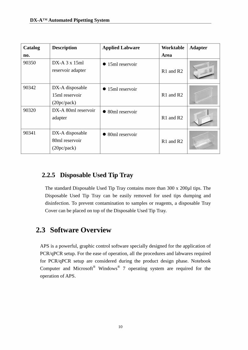
Catalog
no.
Description Applied Labware Worktable
Area
Adapter
90350 DX-A 3 x 15ml
reservoir adapter
15ml reservoir
R1 and R2
90342 DX-A disposable
15ml reservoir
(20pc/pack)
15ml reservoir
R1 and R2
90320 DX-A 80ml reservoir
adapter
80ml reservoir
R1 and R2
90341 DX-A disposable
80ml reservoir
(20pc/pack)
80ml reservoir
R1 and R2
3 Getting Started
11
3 Getting Started
3.1 Unpacking
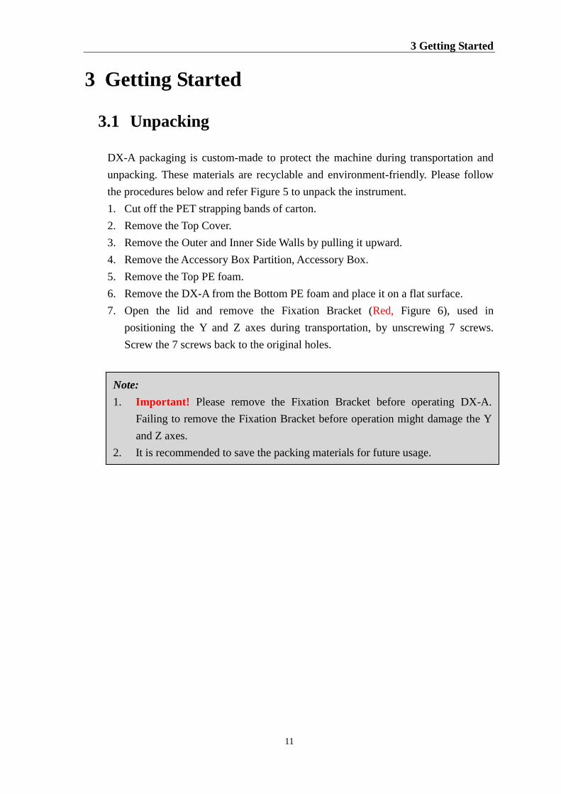
DX-A packaging is custom-made to protect the machine during transportation and
unpacking. These materials are recyclable and environment-friendly. Please follow
the procedures below and refer Figure 5 to unpack the instrument.
1. Cut off the PET strapping bands of carton.
2. Remove the Top Cover.
3. Remove the Outer and Inner Side Walls by pulling it upward.
4. Remove the Accessory Box Partition, Accessory Box.
5. Remove the Top PE foam.
6. Remove the DX-A from the Bottom PE foam and place it on a flat surface.
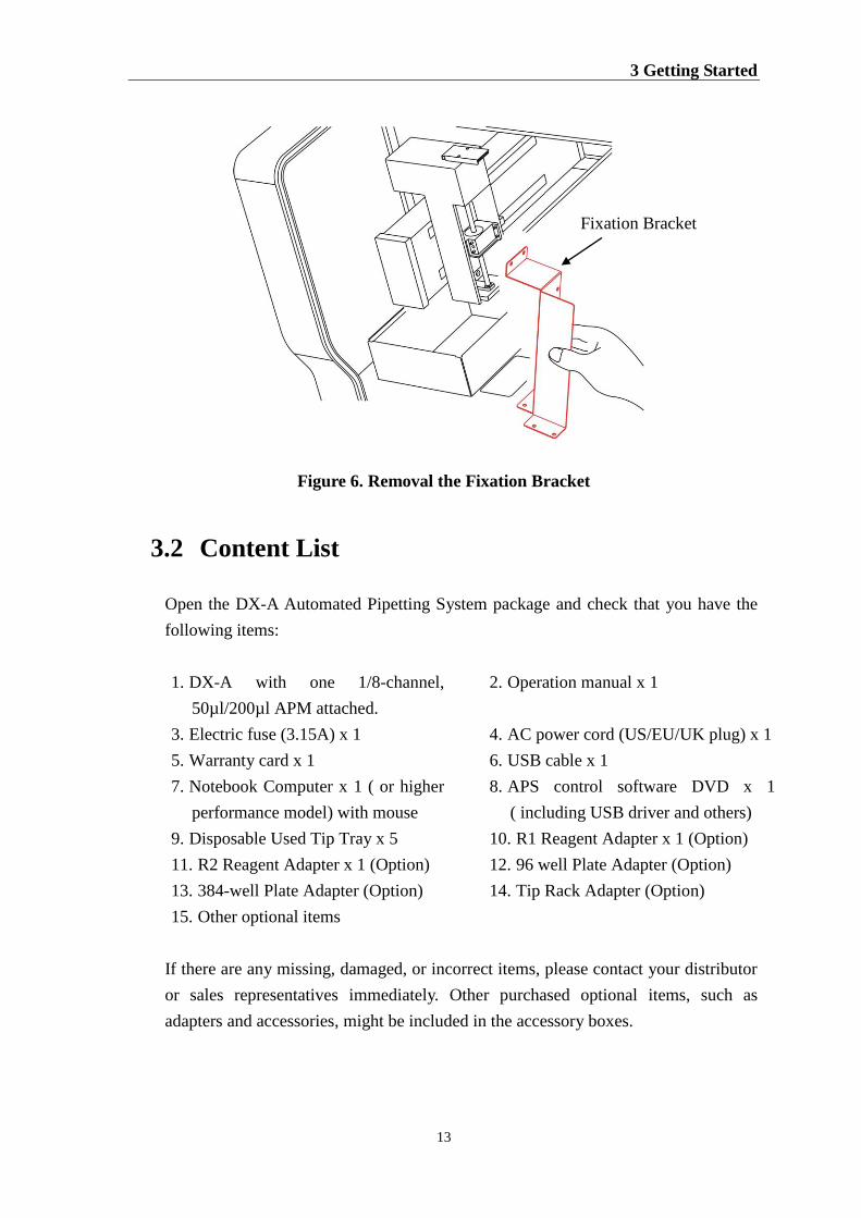
7. Open the lid and remove the Fixation Bracket (Red, Figure 6), used in
positioning the Y and Z axes during transportation, by unscrewing 7 screws.
Screw the 7 screws back to the original holes.
Note:
1. Important! Please remove the Fixation Bracket before operating DX-A.
Failing to remove the Fixation Bracket before operation might damage the Y
and Z axes.
2. It is recommended to save the packing materials for future usage.
DX-A™ Automated Pipetting System
12
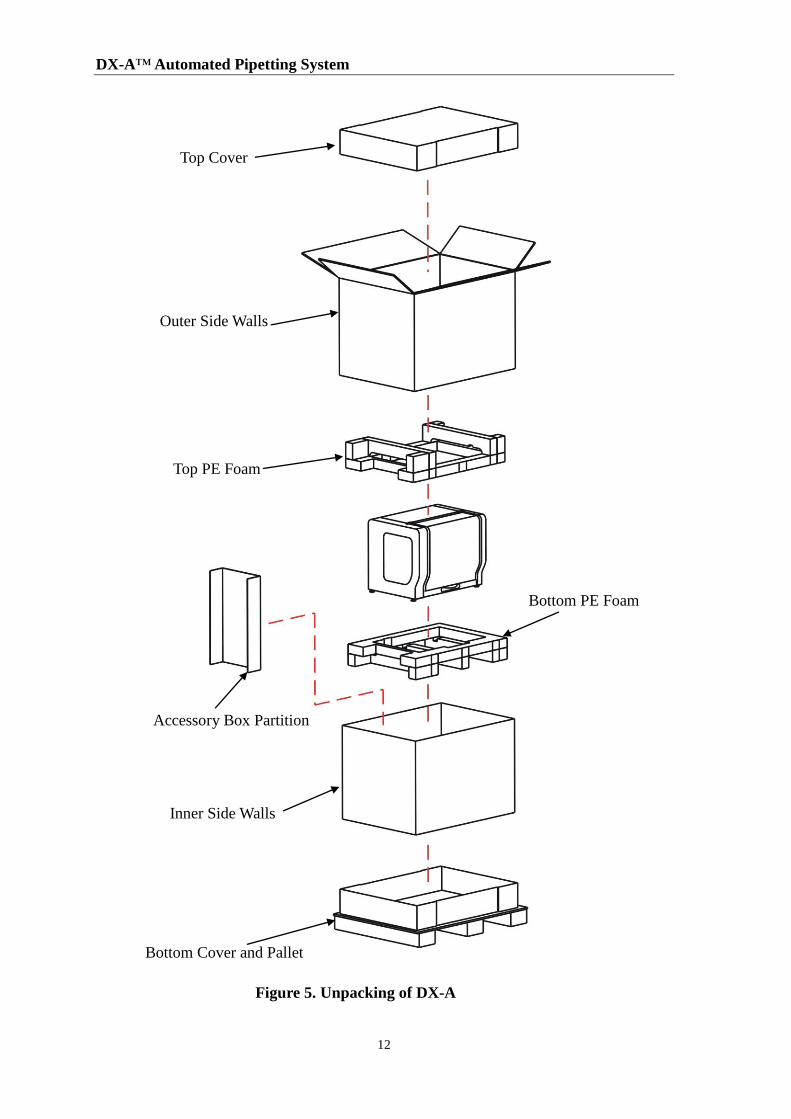
Figure 5. Unpacking of DX-A
Top Cover
Outer Side Walls
Top PE Foam
Bottom Cover and Pallet
Accessory Box Partition
Inner Side Walls
Bottom PE Foam
3 Getting Started
13
Figure 6. Removal the Fixation Bracket
3.2 Content List
Open the DX-A Automated Pipetting System package and check that you have the
following items:
If there are any missing, damaged, or incorrect items, please contact your distributor
or sales representatives immediately. Other purchased optional items, such as
adapters and accessories, might be included in the accessory boxes.
1. DX-A with one 1/8-channel,
50µl/200µl APM attached.
2. Operation manual x 1
3. Electric fuse (3.15A) x 1 4. AC power cord (US/EU/UK plug) x 1
5. Warranty card x 1 6. USB cable x 1
7. Notebook Computer x 1 ( or higher
performance model) with mouse
8. APS control software DVD x 1
( including USB driver and others)
9. Disposable Used Tip Tray x 5 10. R1 Reagent Adapter x 1 (Option)
11. R2 Reagent Adapter x 1 (Option) 12. 96 well Plate Adapter (Option)
13. 384-well Plate Adapter (Option) 14. Tip Rack Adapter (Option)
15. Other optional items
Fixation Bracket
DX-A™ Automated Pipetting System
14
3.3 Instrument Installation
Before running DX-A, users are required to complete and confirm the simple
hardware installations below. If these hardware installations are not implemented
correctly, the APM module might not pick up the tips or liquid correctly and might
collide with the labwares. This might damage the APM.
3.3.1 APM Installation and Removal
The interchangeable 4 Automated Pipetting Modules (APM) provide the
flexibility and convenience. The standard DX-A package is installed with one
single channel 50µl/200µl APM. For different liquid handling applications, users
can order additional APMs. The removal and installation of APM are simple and
do not require any hand tools.
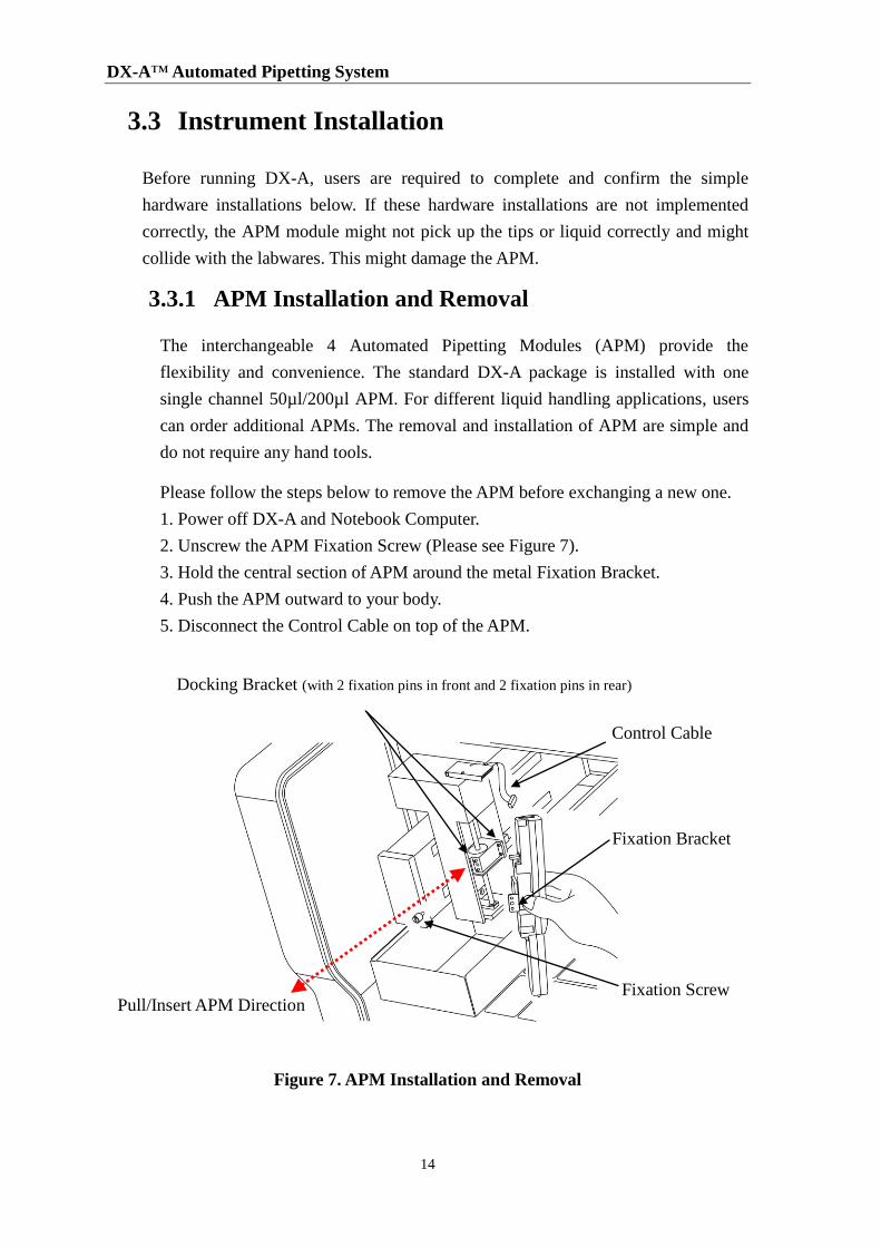
Please follow the steps below to remove the APM before exchanging a new one.
1. Power off DX-A and Notebook Computer.
2. Unscrew the APM Fixation Screw (Please see Figure 7).
3. Hold the central section of APM around the metal Fixation Bracket.
4. Push the APM outward to your body.
5. Disconnect the Control Cable on top of the APM.
Figure 7. APM Installation and Removal
Fixation Bracket
Control Cable
Pull/Insert APM Direction
Docking Bracket (with 2 fixation pins in front and 2 fixation pins in rear)
Fixation Screw
3 Getting Started
15
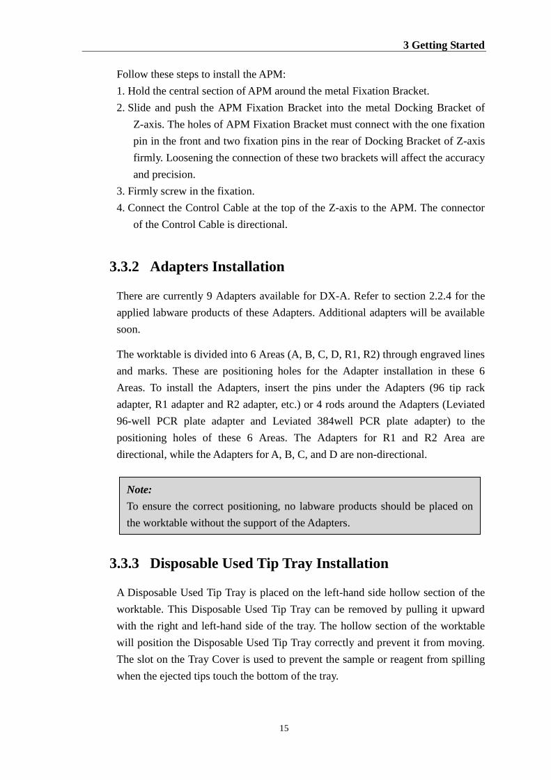
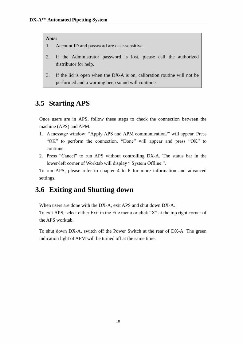
Follow these steps to install the APM:
1. Hold the central section of APM around the metal Fixation Bracket.
2. Slide and push the APM Fixation Bracket into the metal Docking Bracket of
Z-axis. The holes of APM Fixation Bracket must connect with the one fixation
pin in the front and two fixation pins in the rear of Docking Bracket of Z-axis
firmly. Loosening the connection of these two brackets will affect the accuracy
and precision.
3. Firmly screw in the fixation.
4. Connect the Control Cable at the top of the Z-axis to the APM. The connector
of the Control Cable is directional.
3.3.2 Adapters Installation
There are currently 9 Adapters available for DX-A. Refer to section 2.2.4 for the
applied labware products of these Adapters. Additional adapters will be available
soon.
The worktable is divided into 6 Areas (A, B, C, D, R1, R2) through engraved lines
and marks. These are positioning holes for the Adapter installation in these 6
Areas. To install the Adapters, insert the pins under the Adapters (96 tip rack
adapter, R1 adapter and R2 adapter, etc.) or 4 rods around the Adapters (Leviated
96-well PCR plate adapter and Leviated 384well PCR plate adapter) to the
positioning holes of these 6 Areas. The Adapters for R1 and R2 Area are
directional, while the Adapters for A, B, C, and D are non-directional.
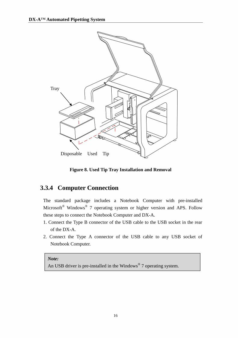
3.3.3 Disposable Used Tip Tray Installation
A Disposable Used Tip Tray is placed on the left-hand side hollow section of the
worktable. This Disposable Used Tip Tray can be removed by pulling it upward
with the right and left-hand side of the tray. The hollow section of the worktable
will position the Disposable Used Tip Tray correctly and prevent it from moving.
The slot on the Tray Cover is used to prevent the sample or reagent from spilling
when the ejected tips touch the bottom of the tray.
Note:
To ensure the correct positioning, no labware products should be placed on
the worktable without the support of the Adapters.
DX-A™ Automated Pipetting System
16
Figure 8. Used Tip Tray Installation and Removal
3.3.4 Computer Connection
The standard package includes a Notebook Computer with pre-installed
Microsoft® Windows
® 7 operating system or higher version and APS. Follow
these steps to connect the Notebook Computer and DX-A.
1. Connect the Type B connector of the USB cable to the USB socket in the rear
of the DX-A.
2. Connect the Type A connector of the USB cable to any USB socket of
Notebook Computer.
Note:
An USB driver is pre-installed in the Windows® 7 operating system.
Tray
Cover
Disposable Used Tip
Tray
3 Getting Started
17
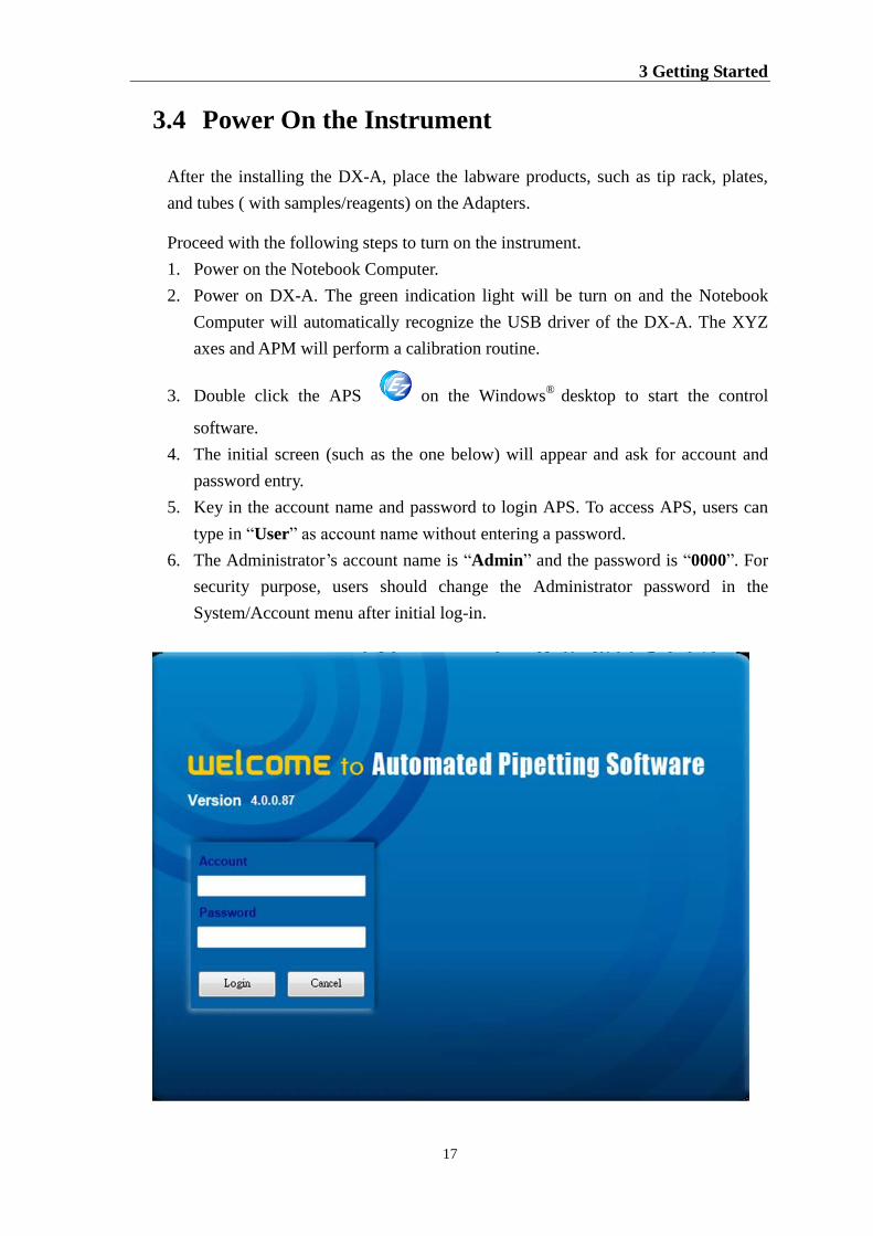
3.4 Power On the Instrument
After the installing the DX-A, place the labware products, such as tip rack, plates,
and tubes ( with samples/reagents) on the Adapters.
Proceed with the following steps to turn on the instrument.
1. Power on the Notebook Computer.
2. Power on DX-A. The green indication light will be turn on and the Notebook
Computer will automatically recognize the USB driver of the DX-A. The XYZ
axes and APM will perform a calibration routine.
3. Double click the APS on the Windows®
desktop to start the control
software.
4. The initial screen (such as the one below) will appear and ask for account and
password entry.
5. Key in the account name and password to login APS. To access APS, users can
type in “User” as account name without entering a password.
6. The Administrator’s account name is “Admin” and the password is “0000”. For
security purpose, users should change the Administrator password in the
System/Account menu after initial log-in.
DX-A™ Automated Pipetting System
18
Note:
1. Account ID and password are case-sensitive.
2. If the Administrator password is lost, please call the authorized
distributor for help.
3. If the lid is open when the DX-A is on, calibration routine will not be
performed and a warning beep sound will continue.
3.5 Starting APS
Once users are in APS, follow these steps to check the connection between the
machine (APS) and APM.
1. A message window: “Apply APS and APM communication?” will appear. Press
“OK” to perform the connection. “Done” will appear and press “OK” to
continue.
2. Press “Cancel” to run APS without controlling DX-A. The status bar in the
lower-left corner of Worktab will display “ System Offline.”.
To run APS, please refer to chapter 4 to 6 for more information and advanced
settings.
3.6 Exiting and Shutting down
When users are done with the DX-A, exit APS and shut down DX-A.
To exit APS, select either Exit in the File menu or click “X” at the top right corner of
the APS worktab.
To shut down DX-A, switch off the Power Switch at the rear of DX-A. The green
indication light of APM will be turned off at the same time.
4 Software
19
4 Software
This chapter provides thorough information on the APS. All elements shown in the
protocol file ( file format: *.aps ) screen, such as the Menus, the Toolbar, the graphic
Worktable section for labware selection, the Protocol section for writing a series of
commands, the Property section for the information of APM and pipetting data and the
Run section, are covered in this chapter.
4.1 Menu Map of APS
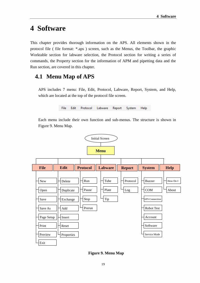
APS includes 7 menu: File, Edit, Protocol, Labware, Report, System, and Help,
which are located at the top of the protocol file screen.
Each menu include their own function and sub-menus. The structure is shown in
Figure 9. Menu Map.
Figure 9. Menu Map
Open
New
Save
Save As
Page Setup
Preview
Exit
Pause
Run
Stop
Prerun
Plate
Tube
Tip
COM
Buzzer
APS Connection
Robot Test
Account
Software
Service Mode
Log
Protocol
About
How Do I
Duplicate
Delete
Exchange
Add
Insert
Reset
Properties
Initial Screen
Menu
File Edit Protocol Labware Report System Help
DX-A™ Automated Pipetting System
20
4.2 File
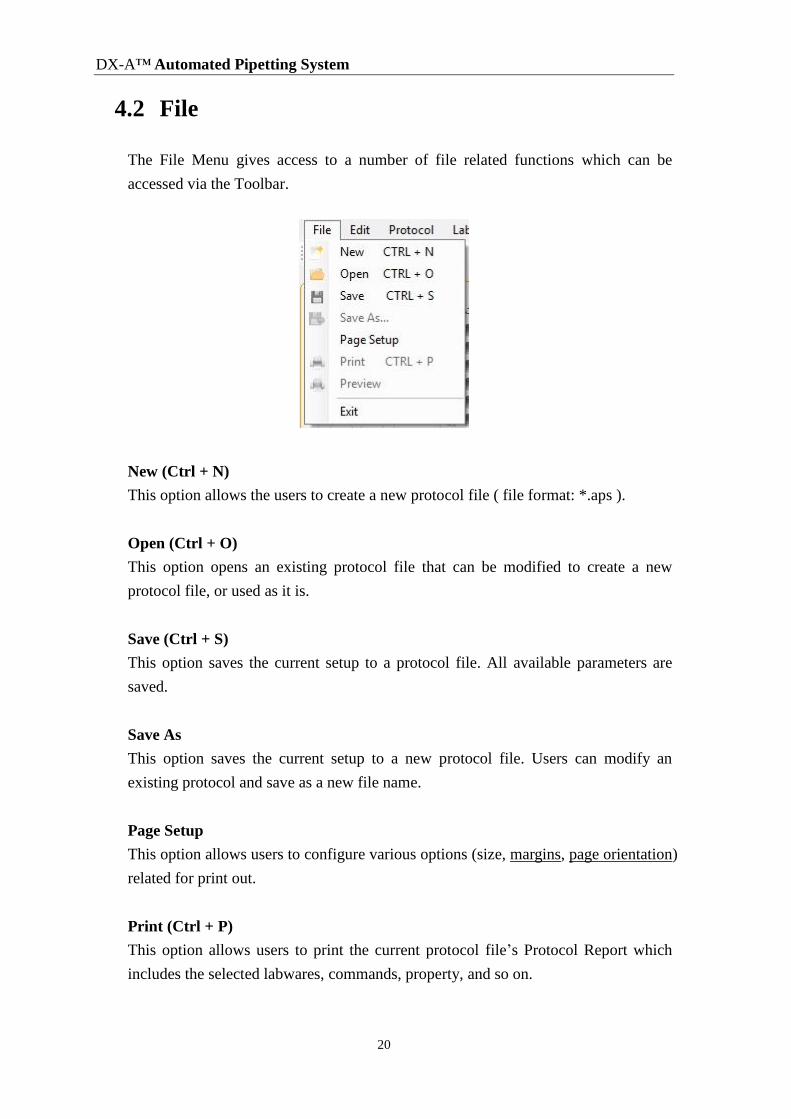
The File Menu gives access to a number of file related functions which can be
accessed via the Toolbar.
New (Ctrl + N)
This option allows the users to create a new protocol file ( file format: *.aps ).
Open (Ctrl + O)
This option opens an existing protocol file that can be modified to create a new
protocol file, or used as it is.
Save (Ctrl + S)
This option saves the current setup to a protocol file. All available parameters are
saved.
Save As
This option saves the current setup to a new protocol file. Users can modify an
existing protocol and save as a new file name.
Page Setup
This option allows users to configure various options (size, margins, page orientation)
related for print out.
Print (Ctrl + P)
This option allows users to print the current protocol file’s Protocol Report which
includes the selected labwares, commands, property, and so on.
4 Software
21
Preview
This option allows users to preview the printing.
Exit (Ctrl + Q)
This option allows users to close the software.
4.3 Edit
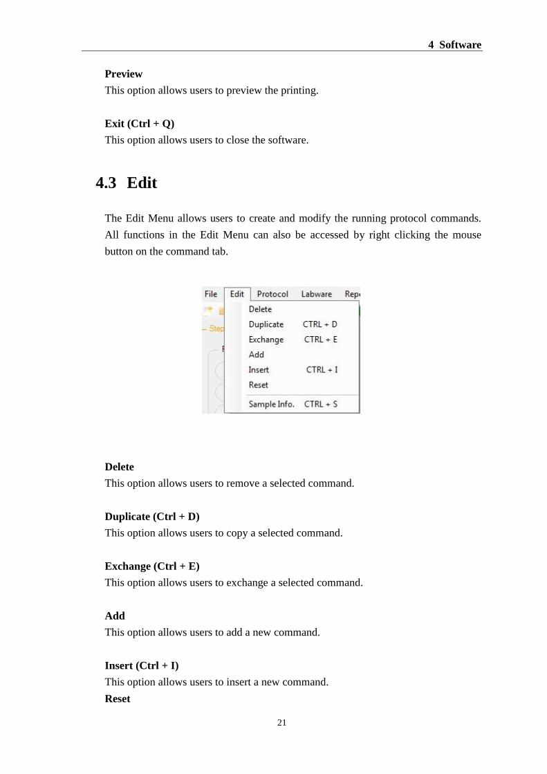
The Edit Menu allows users to create and modify the running protocol commands.
All functions in the Edit Menu can also be accessed by right clicking the mouse
button on the command tab.
Delete
This option allows users to remove a selected command.
Duplicate (Ctrl + D)
This option allows users to copy a selected command.
Exchange (Ctrl + E)
This option allows users to exchange a selected command.
Add
This option allows users to add a new command.
Insert (Ctrl + I)
This option allows users to insert a new command.
Reset
DX-A™ Automated Pipetting System
22
This option allows users to empty the source and destination setting of a selected
command.
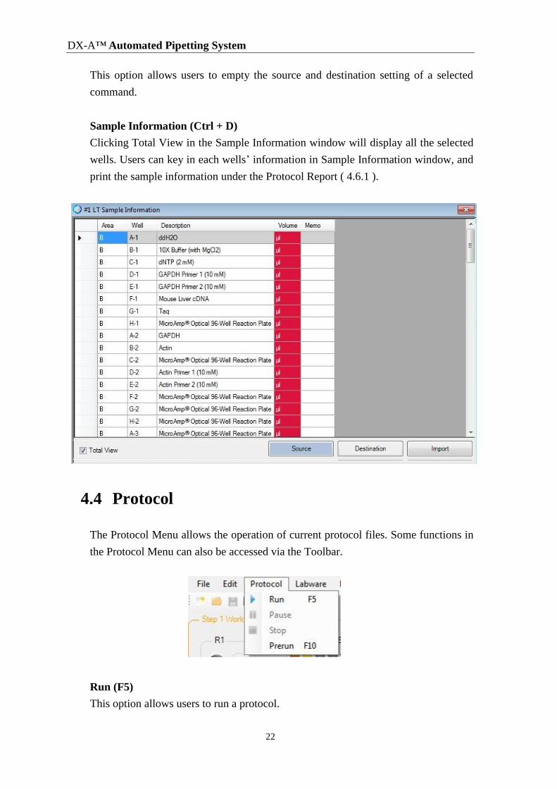
Sample Information (Ctrl + D)
Clicking Total View in the Sample Information window will display all the selected
wells. Users can key in each wells’ information in Sample Information window, and
print the sample information under the Protocol Report ( 4.6.1 ).
4.4 Protocol
The Protocol Menu allows the operation of current protocol files. Some functions in
the Protocol Menu can also be accessed via the Toolbar.
Run (F5)
This option allows users to run a protocol.
4 Software
23
Pause
This option allows users to pause the protocol.
Stop
This option allows users to abort the protocol.
Prerun (F10)
This option allows users to simulate the running process.
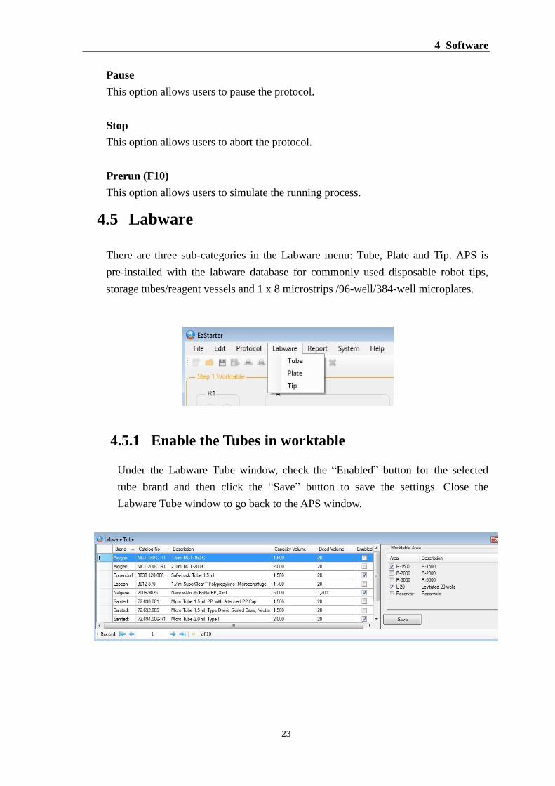
4.5 Labware
There are three sub-categories in the Labware menu: Tube, Plate and Tip. APS is
pre-installed with the labware database for commonly used disposable robot tips,
storage tubes/reagent vessels and 1 x 8 microstrips /96-well/384-well microplates.
4.5.1 Enable the Tubes in worktable
Under the Labware Tube window, check the “Enabled” button for the selected
tube brand and then click the “Save” button to save the settings. Close the
Labware Tube window to go back to the APS window.

DX-A™ Automated Pipetting System
24
4.5.2 Enable the Plates in worktable
Please refer to Section 4.5.1 to enable the plates in worktable, and also check
Dockable Area for the plates to be placed in the selected areas (Area A, B or C).
4.5.3 Enable the Tips in worktable
Please refer to Section 4.5.1 to Enable the tips in worktable.
4.6 Report
The Report Menu allows users to review a protocol report and log records.
Protocol
This option allows users to review a summary of the protocol parameters and
reactions configuration.
Log
This option allows users to review actions that have occurred during system
operation.
4.6.1 Protocol Report
Click the Protocol option under Report Menu. The opened “Protocol Report”
contains the run set up with the following information on:
The protocol name, description and saving location.
Automatic pipetting module (APM) information
All commands settings including Source, Destination, Pipetting Volume,
Pipetting Speed, Mixing etc.
Tip information including brand, type, capacity volume and the amount
required during the run.
Labware configuration, brand, location and the amount of reagent required
during the run.
The current time and date.
Software version

4 Software
25
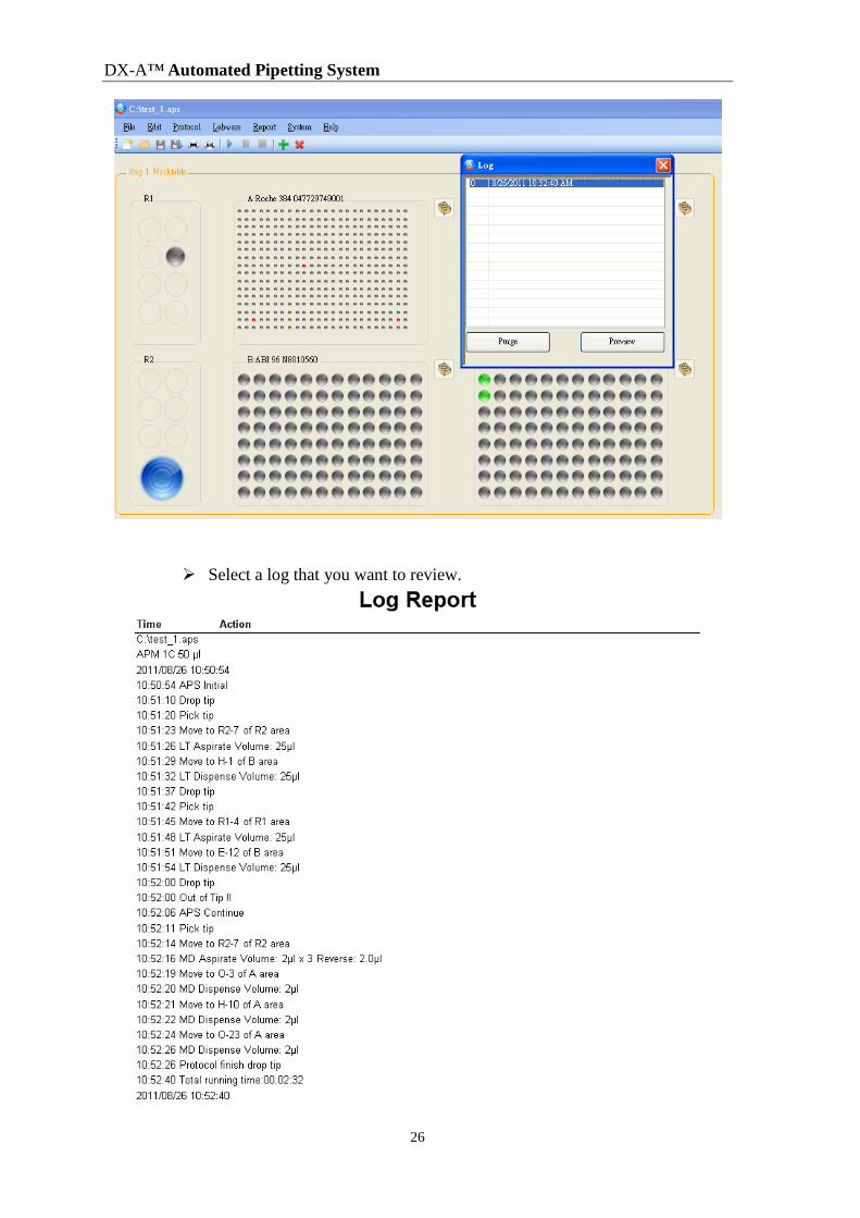
4.6.2 Log Report
The log report records every step of a run. Users can tick off “Log” on the System
Menu (System/Software/Log). A log will be automatically generated when every
protocol is started. Please note that the log will be automatically saved in the
DX-A file (C:\Document\DX-A).
To review the log report, proceed as follows.
Open the protocol for the corresponding log that you want to review.
Click the Log option of Report Menu to display the log record.
DX-A™ Automated Pipetting System
26
Select a log that you want to review.
4 Software
27
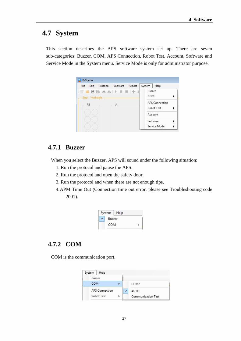
4.7 System
This section describes the APS software system set up. There are seven
sub-categories: Buzzer, COM, APS Connection, Robot Test, Account, Software and
Service Mode in the System menu. Service Mode is only for administrator purpose.
4.7.1 Buzzer
When you select the Buzzer, APS will sound under the following situation:
1. Run the protocol and pause the APS.
2. Run the protocol and open the safety door.
3. Run the protocol and when there are not enough tips.
4. APM Time Out (Connection time out error, please see Troubleshooting code
2001).
4.7.2 COM
COM is the communication port.

DX-A™ Automated Pipetting System
28
Auto
When the computer is connected with APS through the USB, the computer will
auto search a COM port to connect with APS and records the COM port in the
computer.
Communication Test
This function is to test the communication between APS and computer. You
can key in a number in Run Times and click Run to start the Communication
Test. The Result will display OK upon completion. If communication fails,
“APS NOT AVAILABLE” message will be displayed (please see
Troubleshooting).
4.7.3 APS Connection
You can use this function to check the APS connection. In the “Apply APS
connection?” window, click OK and the APS connection will display “Done” or
an “APS NOT AVAILABLE” will be displayed. (please see Troubleshooting).
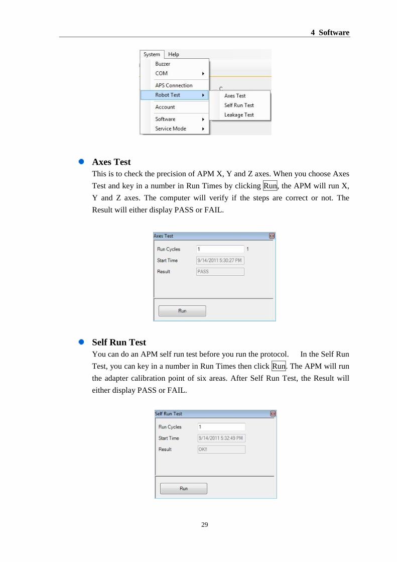
4.7.4 Robot Test
Users can use Robot Test to confirm the basic APS function. There are 3 items:
Axes Test, Self Run Test and Leakage Test in the Robot Test.
4 Software
29
Axes Test
This is to check the precision of APM X, Y and Z axes. When you choose Axes
Test and key in a number in Run Times by clicking Run, the APM will run X,
Y and Z axes. The computer will verify if the steps are correct or not. The
Result will either display PASS or FAIL.
Self Run Test
You can do an APM self run test before you run the protocol. In the Self Run
Test, you can key in a number in Run Times then click Run. The APM will run
the adapter calibration point of six areas. After Self Run Test, the Result will
either display PASS or FAIL.

DX-A™ Automated Pipetting System
30
Leakage Test
Users can use this method to do a tip leakage test.
Leakage test step:
First click on Tip Selection and Plate Selection to choose labwares, and then
put tip rack and 96-well plate on the D and B areas, respectively.
For the 96-well plate, users will need to load enough water with dye (ex.
Bromophenol blue) into H-1 (1 channel) 1 well or A-1 to H-1 (8 channel) 8
wells for the leakage test.
Click Next sequentially to finish the leakage test.
1. Click Next APM will proceed to D area.
2. Click Next APM will fit the tip.
3. Click Next APM will proceed to B area.
4. Click Next APM aspirates 80% volume of liquid (ex. 50μl APM aspirates
40μl liquid, 200μl APM aspirates 160μl liquid), and then
draw a line on the tip with the top of liquid.
5. Click Next Leakage Test window will lock the Next button for 1 minute,
4 Software
31
and after 1 minute if the height of liquid is the same as the
line you previously drew, then the leakage test has passed.
If they are at different height then the leakage test will fail.
6. Click Next APM dispenses liquid.
7. Click Next APM drops the tip.
8. You can click Next to proceed with the leakage test again or click “Close
button (X)” to finish the test.
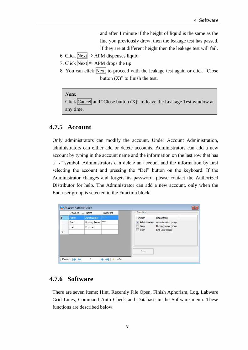
4.7.5 Account
Only administrators can modify the account. Under Account Administration,
administrators can either add or delete accounts. Administrators can add a new
account by typing in the account name and the information on the last row that has
a “*” symbol. Administrators can delete an account and the information by first
selecting the account and pressing the “Del” button on the keyboard. If the
Administrator changes and forgets its password, please contact the Authorized
Distributor for help. The Administrator can add a new account, only when the
End-user group is selected in the Function block.
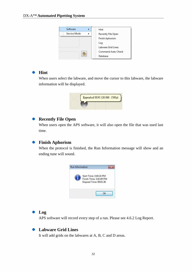
4.7.6 Software
There are seven items: Hint, Recently File Open, Finish Aphorism, Log, Labware
Grid Lines, Command Auto Check and Database in the Software menu. These
functions are described below.
Note:
Click Cancel and “Close button (X)” to leave the Leakage Test window at
any time.
DX-A™ Automated Pipetting System
32
Hint
When users select the labware, and move the cursor to this labware, the labware
information will be displayed.
Recently File Open
When users open the APS software, it will also open the file that was used last
time.
Finish Aphorism
When the protocol is finished, the Run Information message will show and an
ending tune will sound.
Log
APS software will record every step of a run. Please see 4.6.2 Log Report.
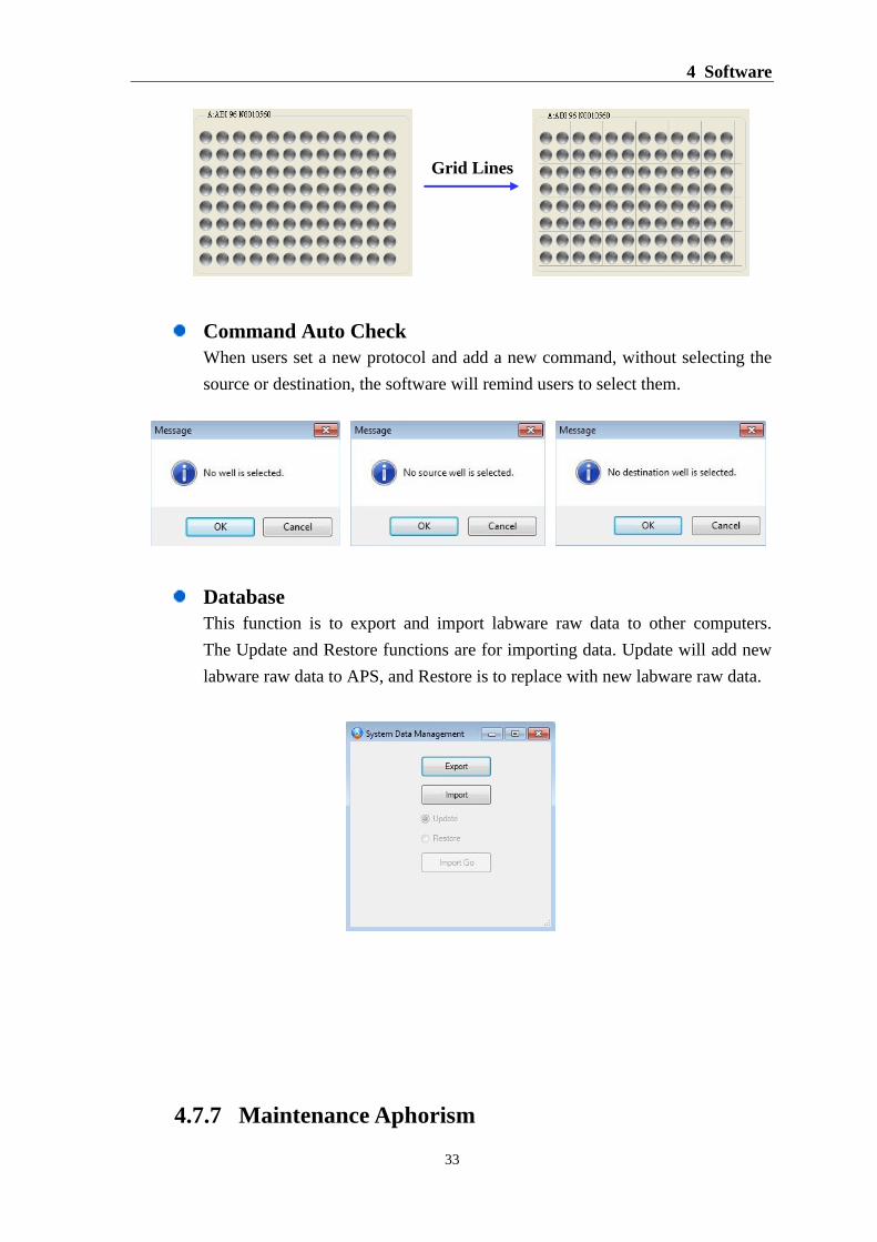
Labware Grid Lines
It will add grids on the labwares at A, B, C and D areas.
4 Software
33
Command Auto Check
When users set a new protocol and add a new command, without selecting the
source or destination, the software will remind users to select them.
Database
This function is to export and import labware raw data to other computers.
The Update and Restore functions are for importing data. Update will add new
labware raw data to APS, and Restore is to replace with new labware raw data.
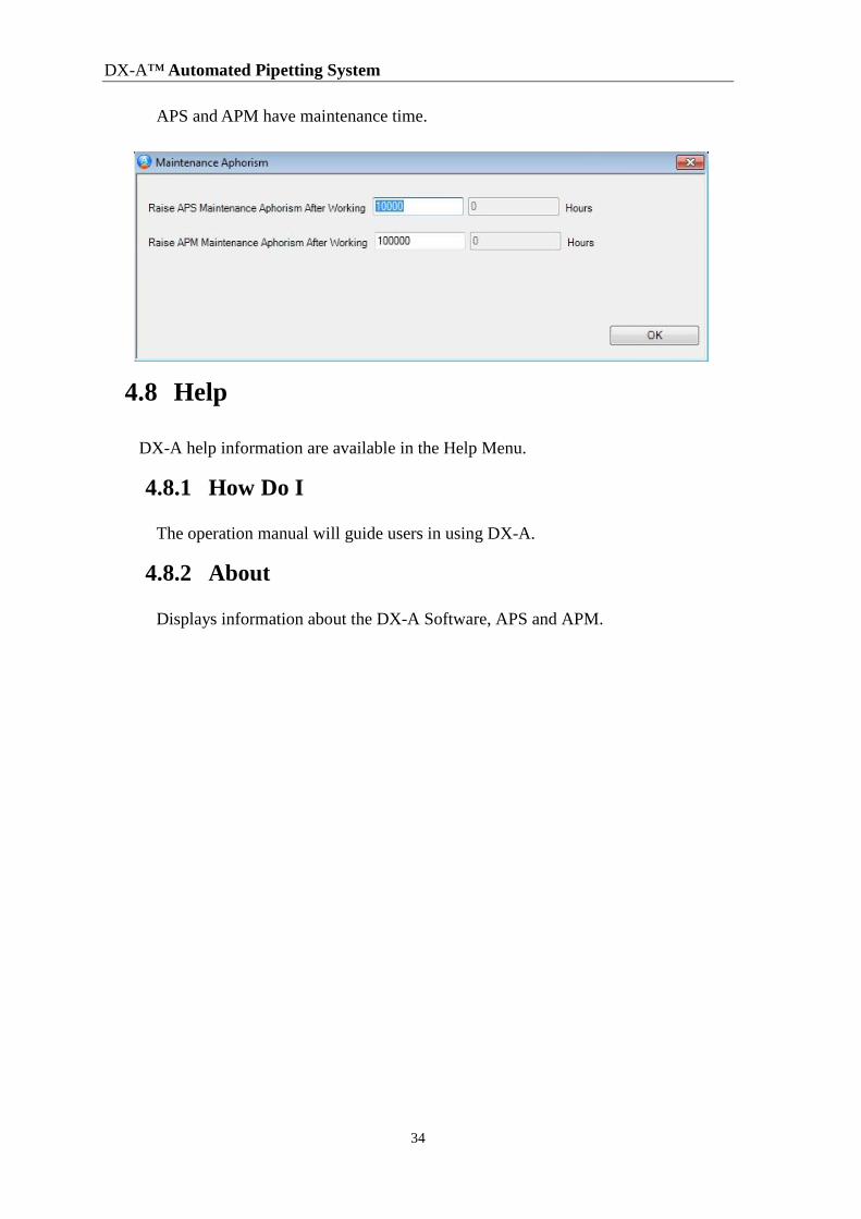
4.7.7 Maintenance Aphorism
Grid Lines
DX-A™ Automated Pipetting System
34
APS and APM have maintenance time.
4.8 Help
DX-A help information are available in the Help Menu.
4.8.1 How Do I
The operation manual will guide users in using DX-A.
4.8.2 About
Displays information about the DX-A Software, APS and APM.
5 Work Tab Overview
35
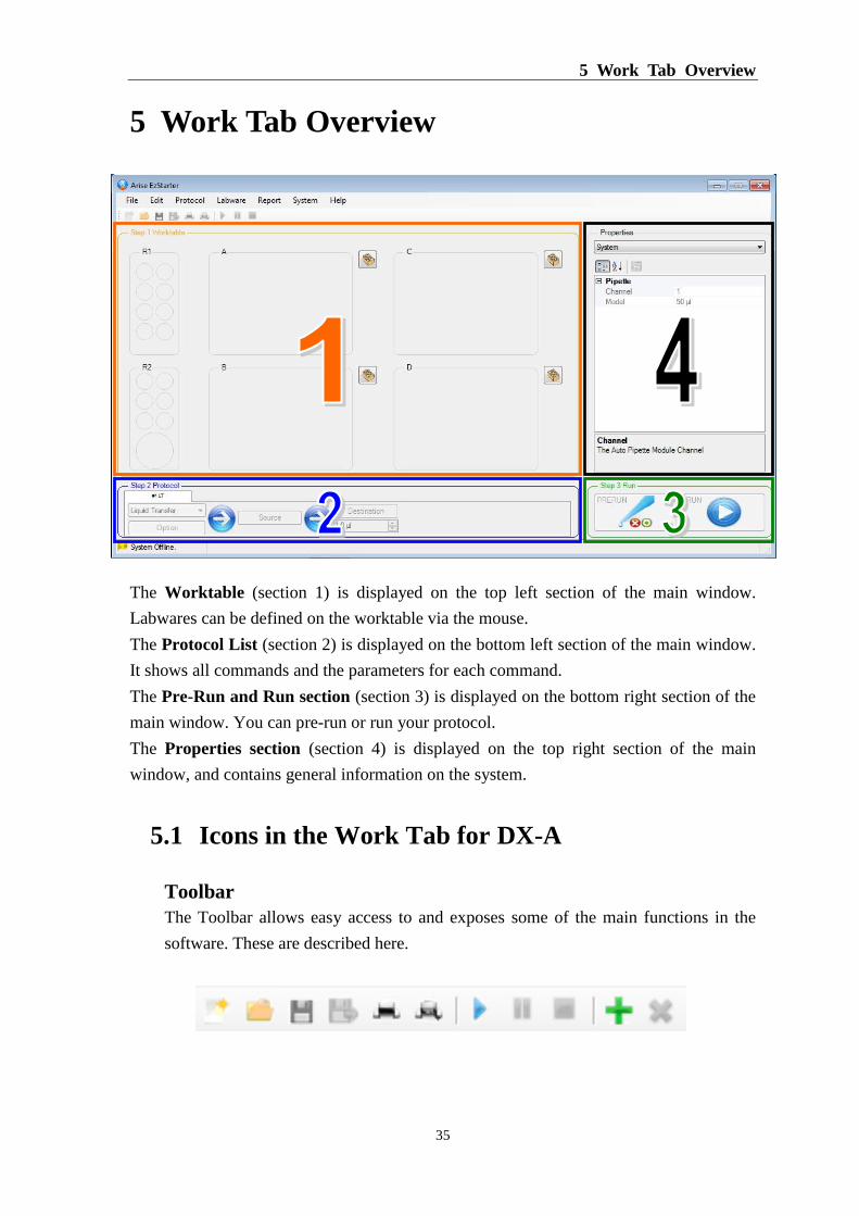
5 Work Tab Overview
The Worktable (section 1) is displayed on the top left section of the main window.
Labwares can be defined on the worktable via the mouse.
The Protocol List (section 2) is displayed on the bottom left section of the main window.
It shows all commands and the parameters for each command.
The Pre-Run and Run section (section 3) is displayed on the bottom right section of the
main window. You can pre-run or run your protocol.
The Properties section (section 4) is displayed on the top right section of the main
window, and contains general information on the system.
5.1 Icons in the Work Tab for DX-A
Toolbar
The Toolbar allows easy access to and exposes some of the main functions in the
software. These are described here.
DX-A™ Automated Pipetting System
36
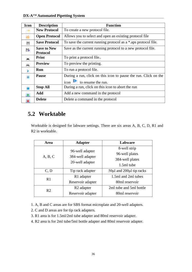
Icon Description Function
New Protocol To create a new protocol file.
Open Protocol Allows you to select and open an existing protocol file
Save Protocol To save the current running protocol as a *.aps protocol file.
Save to New
Protocol
Save as the current running protocol to a new protocol file.
Print To print a protocol file..
Preview To preview the printing.
Run To run a protocol file.
Pause During a run, click on this icon to pause the run. Click on the
icon to resume the run.
Stop All During a run, click on this icon to abort the run
Add Add a new command in the protocol
Delete Delete a command in the protocol
5.2 Worktable
Worktable is designed for labware settings. There are six areas A, B, C, D, R1 and
R2 in worktable.
Area Adapter Labware
A, B, C
96-well adapter
384-well adapter
20-well adapter
8-well strip
96-well plates
384-well plates
1.5ml tube
C, D Tip rack adapter 50μl and 200μl tip racks
R1 R1 adapter
Reservoir adapter
1.5ml and 2ml tubes
80ml reservoir
R2 R2 adapter
Reservoir adapter
2ml tube and 5ml bottle
80ml reservoir
1. A, B and C areas are for SBS format microplate and 20-well adapters.
2. C and D areas are for tip rack adapters.
3. R1 area is for 1.5ml/2ml tube adapter and 80ml reservoir adapter.
4. R2 area is for 2ml tube/5ml bottle adapter and 80ml reservoir adapter.
5 Work Tab Overview
37
5.3 Protocol List
The protocol list shows all commands on the worktable. There are six commands;
Liquid Transfer, Multiple Dispenses, Serial Dilution, Hold, Mixing and Loop.
5.4 Pre-Run and Run
When you set up a new protocol or open a protocol file. You can click PRERUN to
check if the protocol is correct or not, then click RUN to test.
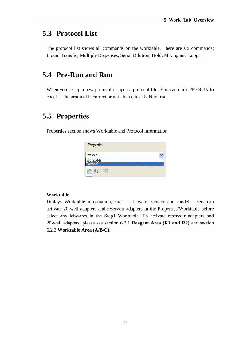
5.5 Properties
Properties section shows Worktable and Protocol information.
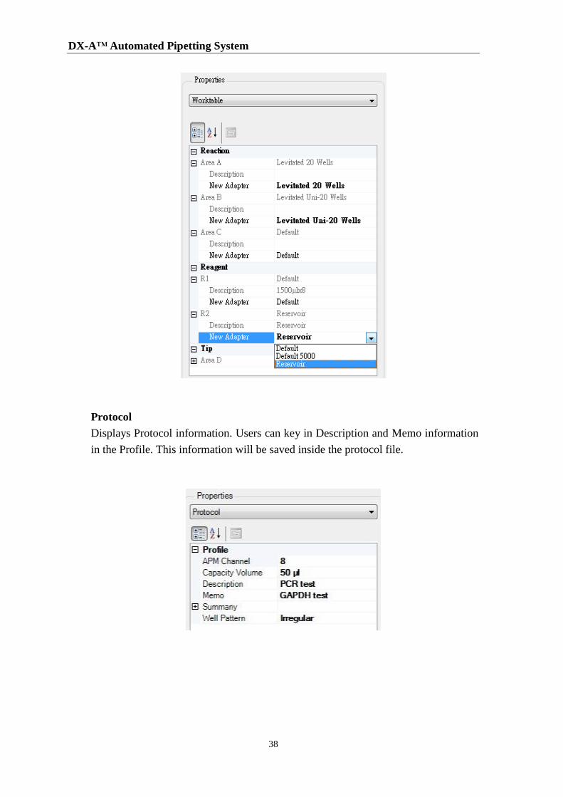
Worktable
Diplays Worktable information, such as labware vendor and model. Users can
activate 20-well adapters and reservoir adapters in the Properties/Worktable before
select any labwares in the Step1 Worktable. To activate reservoir adapters and
20-well adapters, please see section 6.2.1 Reagent Area (R1 and R2) and section
6.2.3 Worktable Area (A/B/C).
DX-A™ Automated Pipetting System
38
Protocol
Displays Protocol information. Users can key in Description and Memo information
in the Profile. This information will be saved inside the protocol file.
6 Operation
39
6 Operation
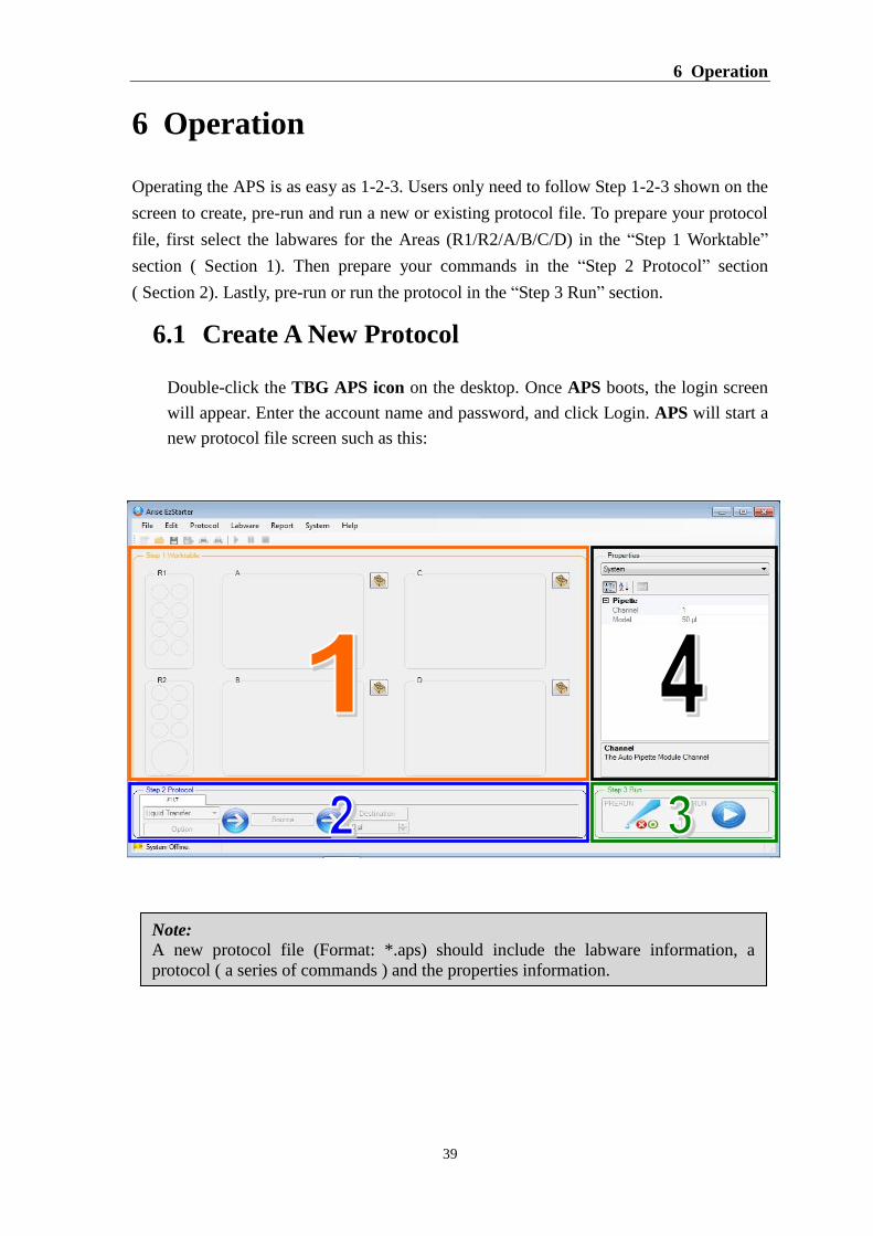
Operating the APS is as easy as 1-2-3. Users only need to follow Step 1-2-3 shown on the
screen to create, pre-run and run a new or existing protocol file. To prepare your protocol
file, first select the labwares for the Areas (R1/R2/A/B/C/D) in the “Step 1 Worktable”
section ( Section 1). Then prepare your commands in the “Step 2 Protocol” section
( Section 2). Lastly, pre-run or run the protocol in the “Step 3 Run” section.
6.1 Create A New Protocol
Double-click the TBG APS icon on the desktop. Once APS boots, the login screen
will appear. Enter the account name and password, and click Login. APS will start a
new protocol file screen such as this:
Note:
A new protocol file (Format: *.aps) should include the labware information, a
protocol ( a series of commands ) and the properties information.

DX-A™ Automated Pipetting System
40
6.2 Selecting the Labwares
Select the labwares after starting a new protocol file. Please follow the section below
to select the labwares for different areas on the worktable. Once the labwares are
selected, the selected labwares and its positions will apply to all commands.
6.2.1 Reagent Area (R1 and R2)
1. If users want to use reservoir, you need to go to Worktable in the Properties,
then click R1 or R2 to choose Reservoir in the New Adapter before selecting
any labwares in the Step1 Worktable.
2. Left-click on the Reagent Area R1 location. The available tube list will be
displayed.
3. Select the tube you want to position on the Reagent Area R. The selected
position will be highlighted in gray.
Default Reservoir
Become
6 Operation
41
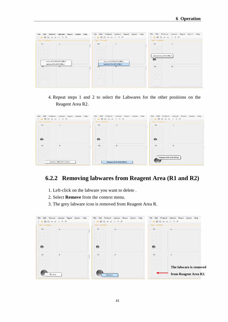
4. Repeat steps 1 and 2 to select the Labwares for the other positions on the
Reagent Area R2.
6.2.2 Removing labwares from Reagent Area (R1 and R2)
1. Left-click on the labware you want to delete .
2. Select Remove from the context menu.
3. The grey labware icon is removed from Reagent Area R.
The labware is removed
from Reagent Area R2.
DX-A™ Automated Pipetting System
42
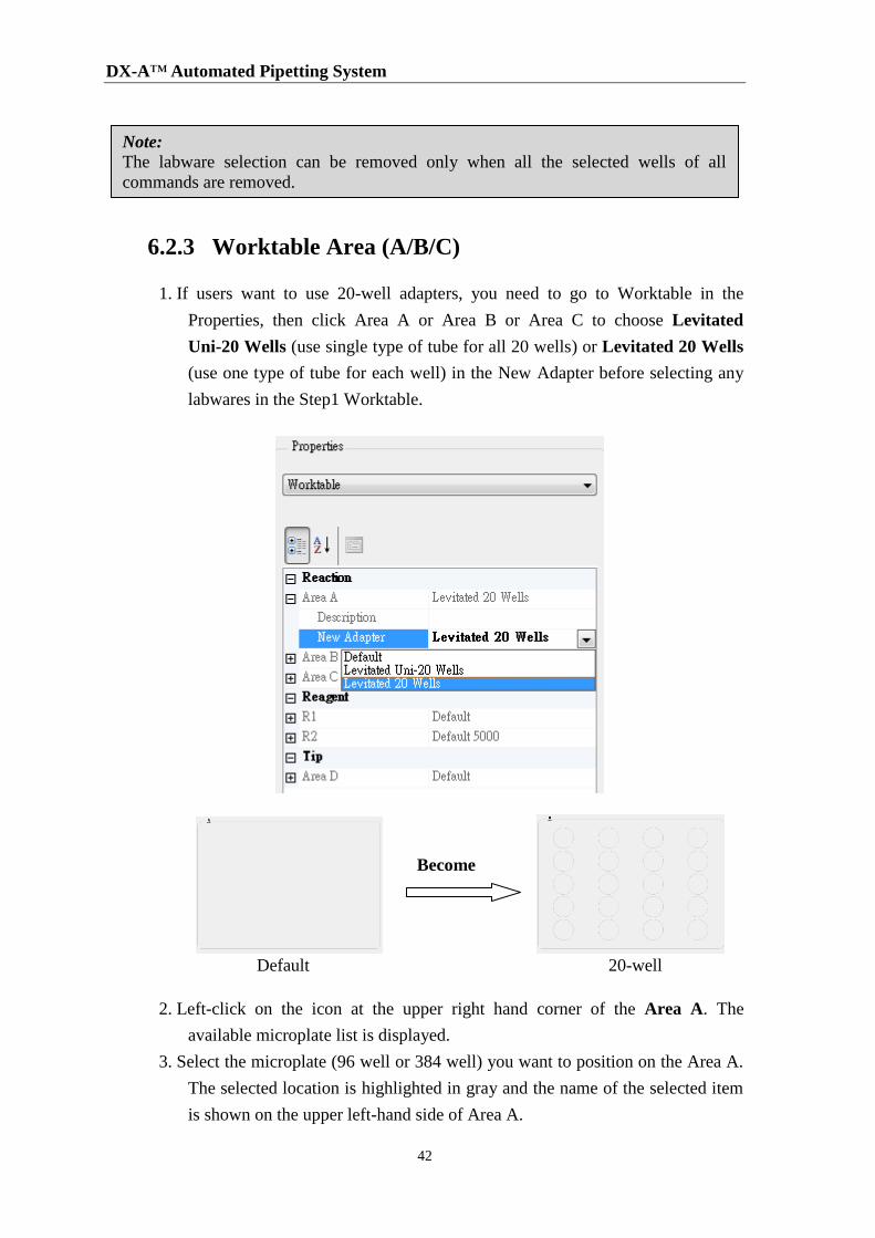
6.2.3 Worktable Area (A/B/C)
1. If users want to use 20-well adapters, you need to go to Worktable in the
Properties, then click Area A or Area B or Area C to choose Levitated
Uni-20 Wells (use single type of tube for all 20 wells) or Levitated 20 Wells
(use one type of tube for each well) in the New Adapter before selecting any
labwares in the Step1 Worktable.
2. Left-click on the icon at the upper right hand corner of the Area A. The
available microplate list is displayed.
3. Select the microplate (96 well or 384 well) you want to position on the Area A.
The selected location is highlighted in gray and the name of the selected item
is shown on the upper left-hand side of Area A.
Note:
The labware selection can be removed only when all the selected wells of all
commands are removed.
Default 20-well
Become
6 Operation
43
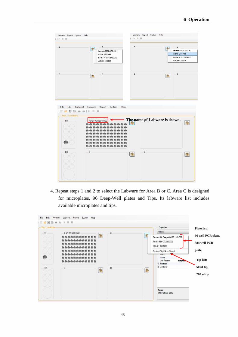
4. Repeat steps 1 and 2 to select the Labware for Area B or C. Area C is designed
for microplates, 96 Deep-Well plates and Tips. Its labware list includes
available microplates and tips.
The name of Labware is shown.
Plate list:
96 well PCR plate,
384 well PCR
plate,
96 Deep-well
plate
Tip list:
50 ul tip,
200 ul tip
DX-A™ Automated Pipetting System
44
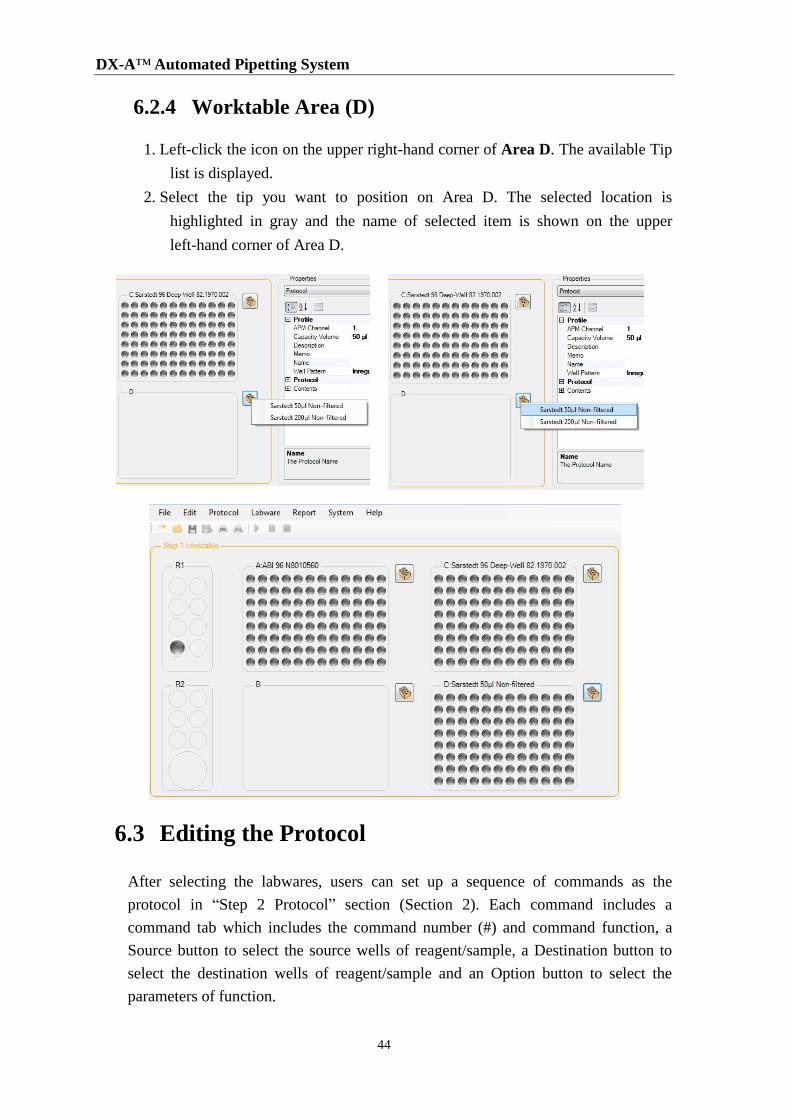
6.2.4 Worktable Area (D)
1. Left-click the icon on the upper right-hand corner of Area D. The available Tip
list is displayed.
2. Select the tip you want to position on Area D. The selected location is
highlighted in gray and the name of selected item is shown on the upper
left-hand corner of Area D.
6.3 Editing the Protocol
After selecting the labwares, users can set up a sequence of commands as the
protocol in “Step 2 Protocol” section (Section 2). Each command includes a
command tab which includes the command number (#) and command function, a
Source button to select the source wells of reagent/sample, a Destination button to
select the destination wells of reagent/sample and an Option button to select the
parameters of function.
6 Operation
45
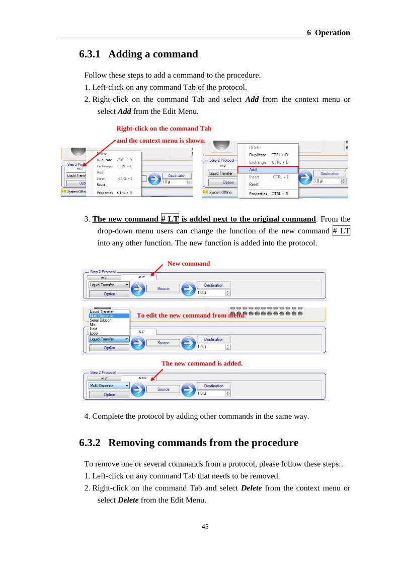
6.3.1 Adding a command
Follow these steps to add a command to the procedure.
1. Left-click on any command Tab of the protocol.
2. Right-click on the command Tab and select Add from the context menu or
select Add from the Edit Menu.
3. The new command # LT is added next to the original command. From the
drop-down menu users can change the function of the new command # LT
into any other function. The new function is added into the protocol.
4. Complete the protocol by adding other commands in the same way.
6.3.2 Removing commands from the procedure
To remove one or several commands from a protocol, please follow these steps:.
1. Left-click on any command Tab that needs to be removed.
2. Right-click on the command Tab and select Delete from the context menu or
select Delete from the Edit Menu.
Right-click on the command Tab
and the context menu is shown.
New command
To edit the new command from menu.
The new command is added.
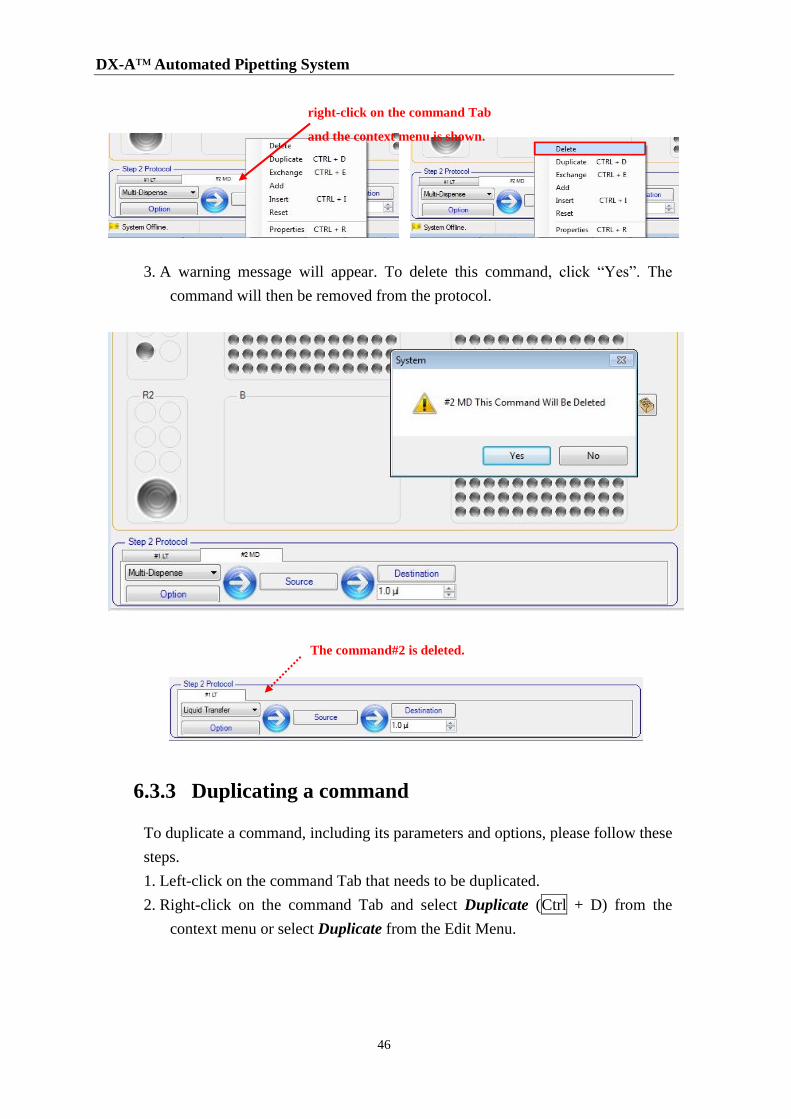
DX-A™ Automated Pipetting System
46
3. A warning message will appear. To delete this command, click “Yes”. The
command will then be removed from the protocol.
6.3.3 Duplicating a command
To duplicate a command, including its parameters and options, please follow these
steps.
1. Left-click on the command Tab that needs to be duplicated.
2. Right-click on the command Tab and select Duplicate (Ctrl + D) from the
context menu or select Duplicate from the Edit Menu.
right-click on the command Tab
and the context menu is shown.
The command#2 is deleted.
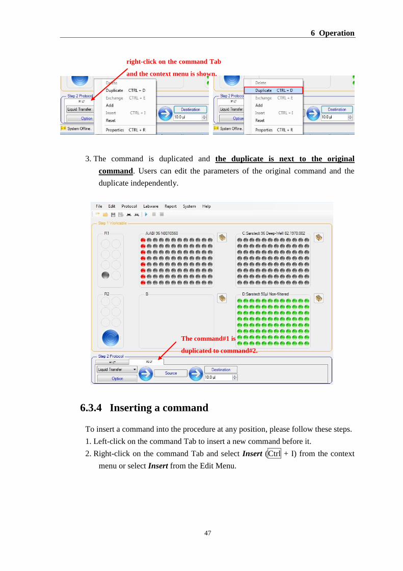
6 Operation
47
3. The command is duplicated and the duplicate is next to the original
command. Users can edit the parameters of the original command and the
duplicate independently.
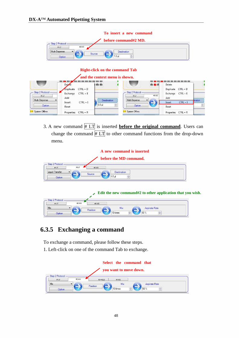
6.3.4 Inserting a command
To insert a command into the procedure at any position, please follow these steps.
1. Left-click on the command Tab to insert a new command before it.
2. Right-click on the command Tab and select Insert (Ctrl + I) from the context
menu or select Insert from the Edit Menu.
right-click on the command Tab
and the context menu is shown.
The command#1 is
duplicated to command#2.
DX-A™ Automated Pipetting System
48
3. A new command # LT is inserted before the original command. Users can
change the command # LT to other command functions from the drop-down
menu.
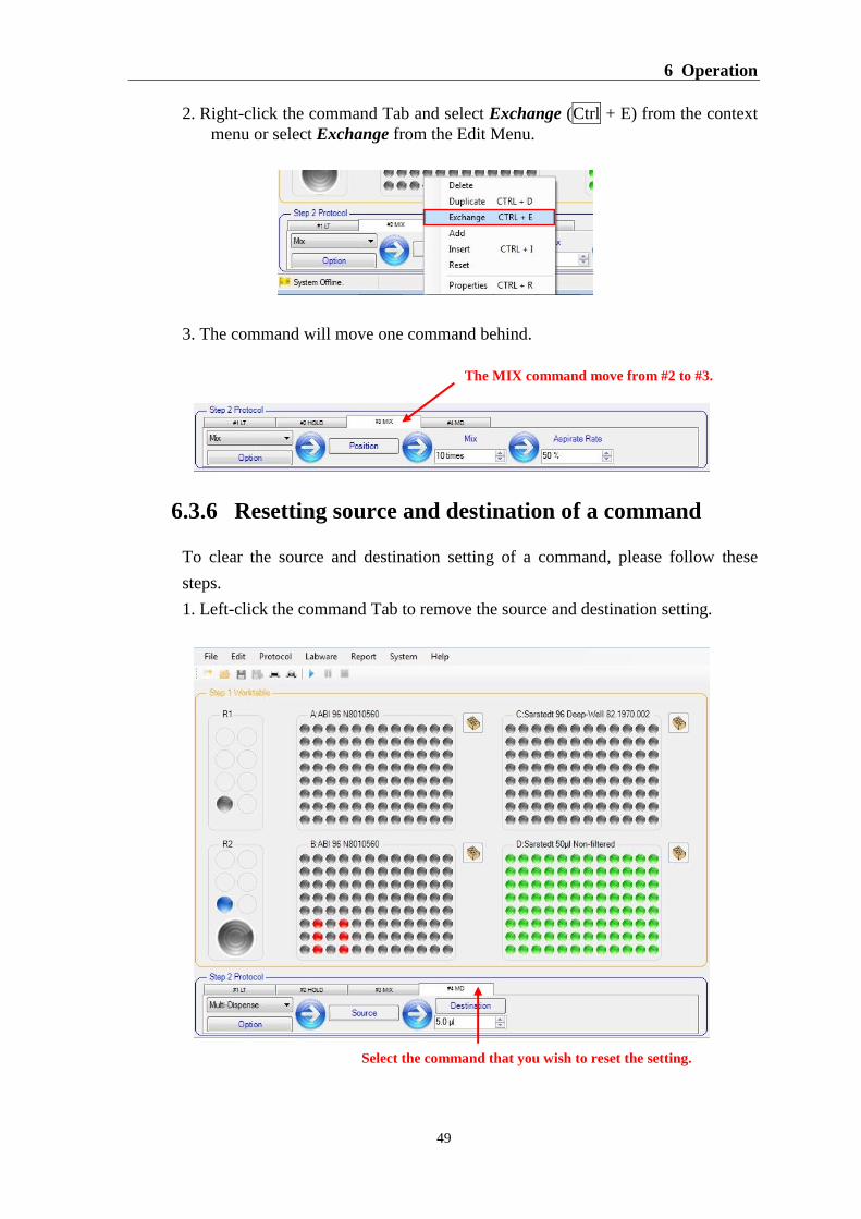
6.3.5 Exchanging a command
To exchange a command, please follow these steps.
1. Left-click on one of the command Tab to exchange.
Right-click on the command Tab
and the context menu is shown.
To insert a new command
before command#2 MD.
A new command is inserted
before the MD command.
Edit the new command#2 to other application that you wish.
Select the command that
you want to move down.
6 Operation
49
2. Right-click the command Tab and select Exchange (Ctrl + E) from the context
menu or select Exchange from the Edit Menu.
3. The command will move one command behind.
6.3.6 Resetting source and destination of a command
To clear the source and destination setting of a command, please follow these
steps.
1. Left-click the command Tab to remove the source and destination setting.
The MIX command move from #2 to #3.
Select the command that you wish to reset the setting.
DX-A™ Automated Pipetting System
50
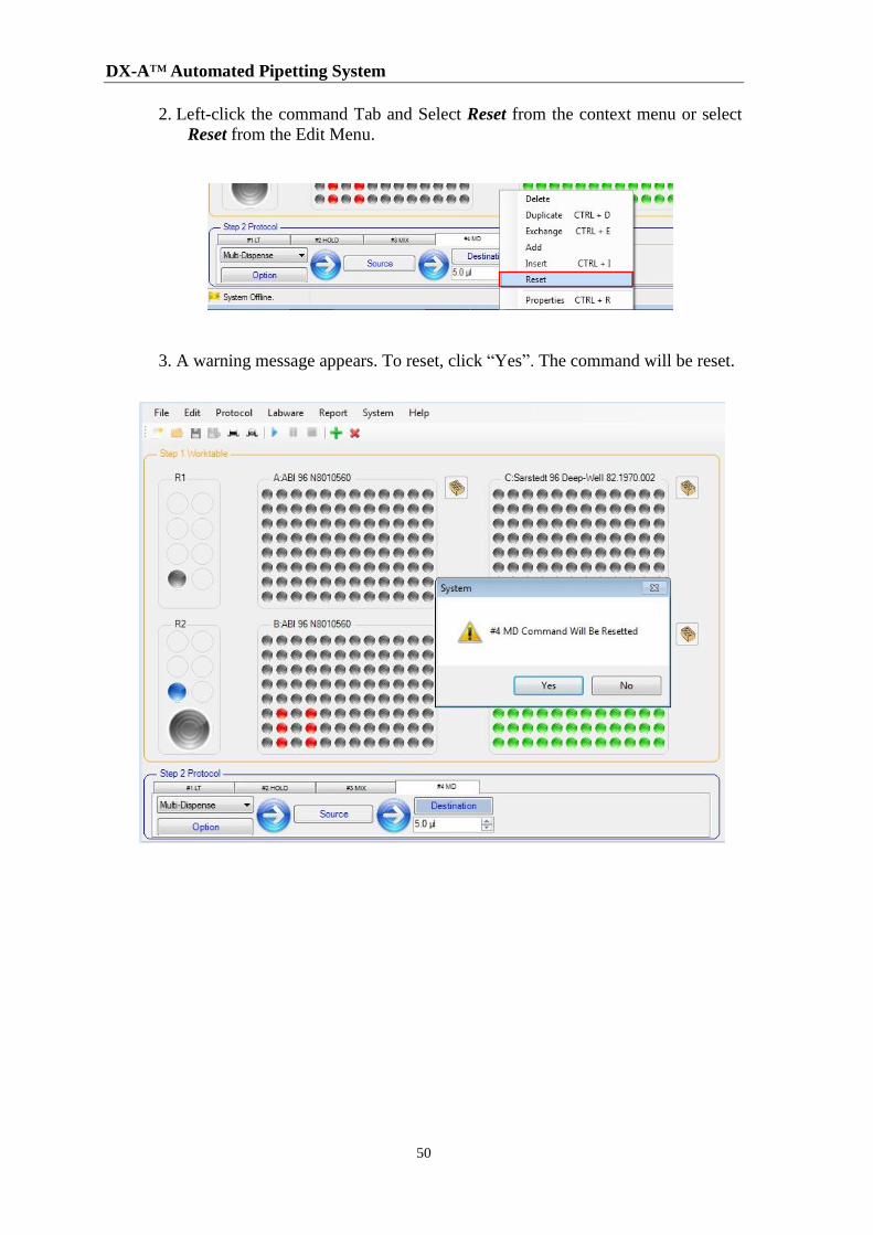
2. Left-click the command Tab and Select Reset from the context menu or select
Reset from the Edit Menu.
3. A warning message appears. To reset, click “Yes”. The command will be reset.
6 Operation
51
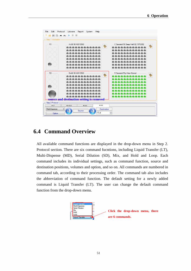
6.4 Command Overview
All available command functions are displayed in the drop-down menu in Step 2.
Protocol section. There are six command fucntions, including Liquid Transfer (LT),
Multi-Dispense (MD), Serial Dilution (SD), Mix, and Hold and Loop. Each
command includes its individual settings, such as command function, source and
destination positions, volumes and option, and so on. All commands are numbered in
command tab, according to their processing order. The command tab also includes
the abbreviation of command function. The default setting for a newly added
command is Liquid Transfer (LT). The user can change the default command
function from the drop-down menu.
source and destination setting is removed
Click the drop-down menu, there
are 6 commands.
DX-A™ Automated Pipetting System
52
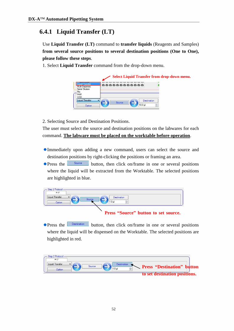
6.4.1 Liquid Transfer (LT)
Use Liquid Transfer (LT) command to transfer liquids (Reagents and Samples)
from several source positions to several destination positions (One to One),
please follow these steps.
1. Select Liquid Transfer command from the drop-down menu.
2. Selecting Source and Destination Positions.
The user must select the source and destination positions on the labwares for each
command. The labware must be placed on the worktable before operation.
Immediately upon adding a new command, users can select the source and
destination positions by right-clicking the positions or framing an area.
Press the button, then click on/frame in one or several positions
where the liquid will be extracted from the Worktable. The selected positions
are highlighted in blue.
Press the button, then click on/frame in one or several positions
where the liquid will be dispensed on the Worktable. The selected positions are
highlighted in red.
Select Liquid Transfer from drop-down menu.
Press “Source” button to set source.
positions
Press “Destination” button
to set destination positions.
6 Operation
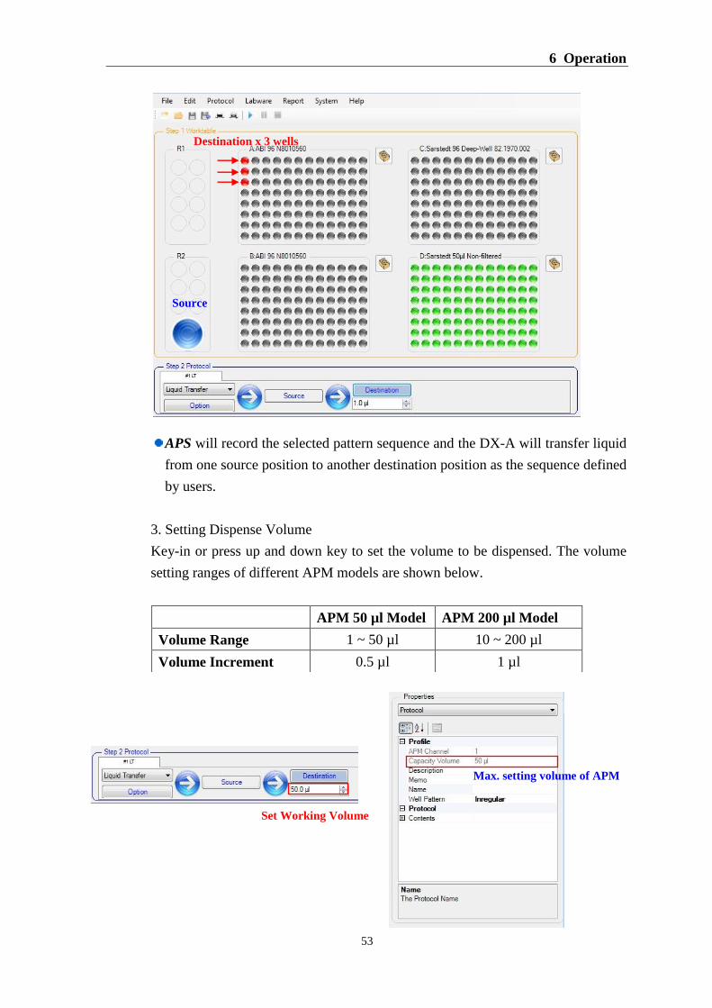
53
APS will record the selected pattern sequence and the DX-A will transfer liquid
from one source position to another destination position as the sequence defined
by users.
3. Setting Dispense Volume
Key-in or press up and down key to set the volume to be dispensed. The volume
setting ranges of different APM models are shown below.
APM 50 µl Model APM 200 µl Model
Volume Range 1 ~ 50 µl 10 ~ 200 µl
Volume Increment 0.5 µl 1 µl
Source
Destination x 3 wells
Max. setting volume of APM
Set Working Volume
DX-A™ Automated Pipetting System
54
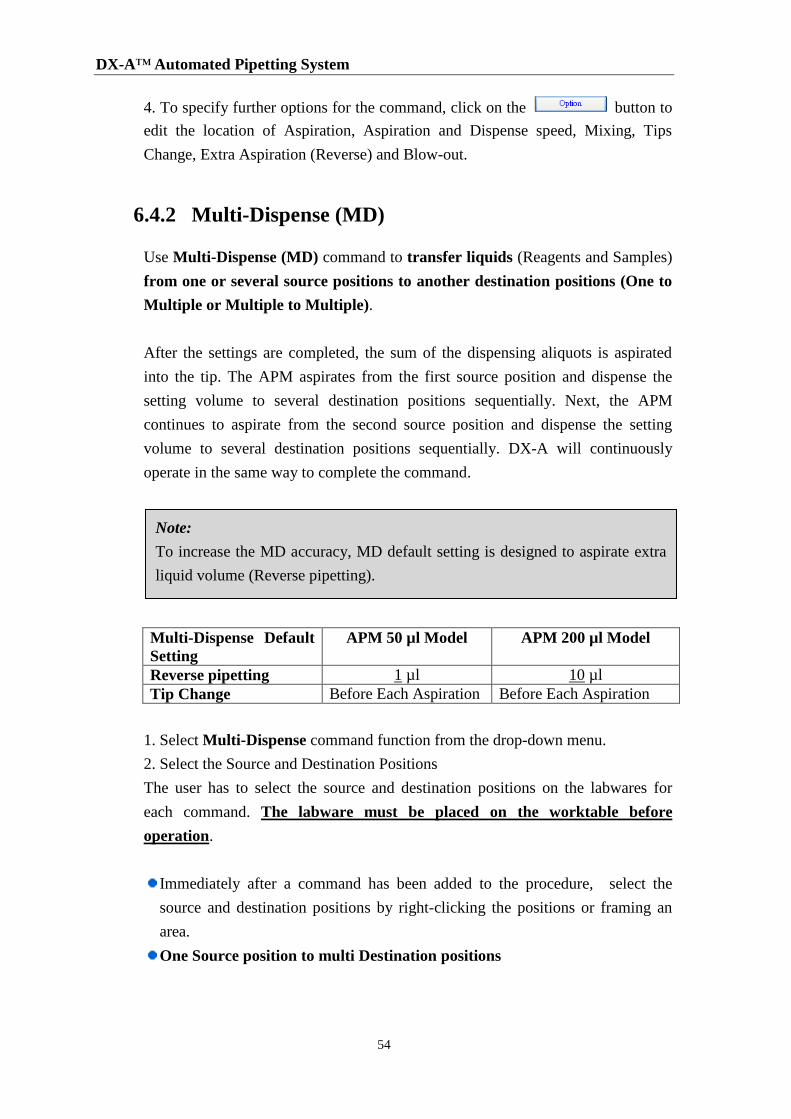
4. To specify further options for the command, click on the button to
edit the location of Aspiration, Aspiration and Dispense speed, Mixing, Tips
Change, Extra Aspiration (Reverse) and Blow-out.
6.4.2 Multi-Dispense (MD)
Use Multi-Dispense (MD) command to transfer liquids (Reagents and Samples)
from one or several source positions to another destination positions (One to
Multiple or Multiple to Multiple).
After the settings are completed, the sum of the dispensing aliquots is aspirated
into the tip. The APM aspirates from the first source position and dispense the
setting volume to several destination positions sequentially. Next, the APM
continues to aspirate from the second source position and dispense the setting
volume to several destination positions sequentially. DX-A will continuously
operate in the same way to complete the command.
Multi-Dispense Default
Setting
APM 50 µl Model APM 200 µl Model
Reverse pipetting 1 µl 10 µl
Tip Change Before Each Aspiration Before Each Aspiration
1. Select Multi-Dispense command function from the drop-down menu.
2. Select the Source and Destination Positions
The user has to select the source and destination positions on the labwares for
each command. The labware must be placed on the worktable before
operation.
Immediately after a command has been added to the procedure, select the
source and destination positions by right-clicking the positions or framing an
area.
One Source position to multi Destination positions
Note:
To increase the MD accuracy, MD default setting is designed to aspirate extra
liquid volume (Reverse pipetting).
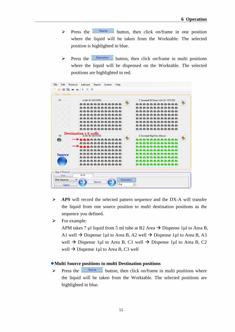
6 Operation
55
Press the button, then click on/frame in one position
where the liquid will be taken from the Worktable. The selected
position is highlighted in blue.
Press the button, then click on/frame in multi positions
where the liquid will be dispensed on the Worktable. The selected
positions are highlighted in red.
APS will record the selected pattern sequence and the DX-A will transfer
the liquid from one source position to multi destination positions as the
sequence you defined.
For example:
APM takes 7 µl liquid from 5 ml tube at R2 Area Dispense 1µl to Area B,
A1 well Dispense 1µl to Area B, A2 well Dispense 1µl to Area B, A3
well Dispense 1µl to Area B, C1 well Dispense 1µl to Area B, C2
well Dispense 1µl to Area B, C3 well
Multi Source positions to multi Destination positions
Press the button, then click on/frame in multi positions where
the liquid will be taken from the Worktable. The selected positions are
highlighted in blue.
Source
Destination x 6 wells
DX-A™ Automated Pipetting System
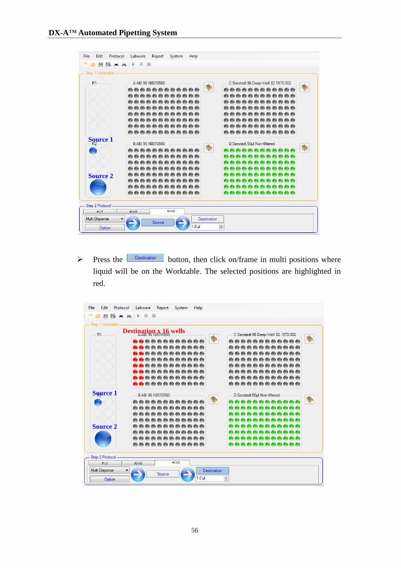
56
Press the button, then click on/frame in multi positions where
liquid will be on the Worktable. The selected positions are highlighted in
red.
Source 1
Source 2
Source 2
Destination x 16 wells
Source 1
6 Operation
57
APS will record the selected pattern sequence and the DX-A will transfer
the liquid from multi source positions to multi destination positions as the
sequence defined by users.
For example:
APM takes 17 µl liquid from 2 ml tube at R2 Area Dispense 1µl to
Area A, A1 well 1µl to B1 well 1µl to C1 1µl to D1 1µl to E1
1µl to F1 1µl to G1 1µl to H1 1µl to A2 1µl to B2 1µl to
C2 1µl to D2 1µl to E2 1µl to F2 1µl to G2 1µl to H2
Change Tip APM takes 17 µl liquid from 5 ml tube at R2 Area
Dispense 1ul to Area A, A1 well 1µl to B1 1µl to C1 1µl to D1
1µl to E1 1µl to F1 1µl to G1 1µl to H1 1µl to A2 1µl to
B2 1µl to C2 1µl to D2 1µl to E2 1µl to F2 1µl to G2
1µl to H2
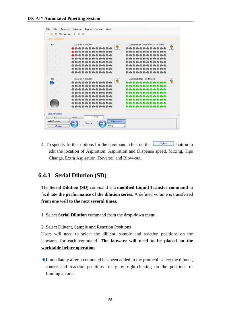
3. Set the dispense volume
Key-in or press the up and down key to set the volume to be dispensed. The
volume setting range is based on the APM model. If the dispense volume of each
well x number of Destination Wells is greater than the maximum APM
volume, then the APM will perform additional pipetting cycle.
For example:
APM Model: 50 µl
Dispense volume/each well: 20 µl
No. of Destination Wells: 3
The APM aspirates 40 µl (20 µl x 2 wells = 40 µl < the APM Max. volume: 50 µl)
from the source position and dispenses the setting volume to the first two
destination positions sequentially. Next, the APM continues to aspirate 20 µl from
the source position and dispense to the third destination position.
For example:
APM takes 41 µl liquid from 2 ml tube at R2 Area Dispense 20 µl to
Area A, A1 well Dispense 20 µl to B1 well Change Tip APM
takes 21 µl liquid from 2 ml tube at R2 Area Dispense 20 µl to C1 well
DX-A™ Automated Pipetting System
58
4. To specify further options for the command, click on the button to
edit the location of Aspiration, Aspiration and Dispense speed, Mixing, Tips
Change, Extra Aspiration (Reverse) and Blow-out.
6.4.3 Serial Dilution (SD)
The Serial Dilution (SD) command is a modified Liquid Transfer command to
facilitate the performance of the dilution series. A defined volume is transferred
from one well to the next several times.
1. Select Serial Dilution command from the drop-down menu.
2. Select Diluent, Sample and Reaction Positions
Users will need to select the diluent, sample and reaction positions on the
labwares for each command. The labware will need to be placed on the
worktable before operation.
Immediately after a command has been added to the protocol, select the diluent,
source and reaction positions freely by right-clicking on the positions or
framing an area.
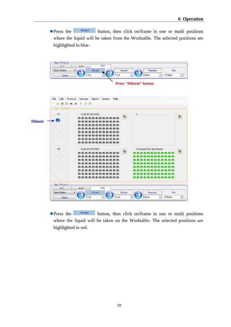
6 Operation
59
Press the button, then click on/frame in one or multi positions
where the liquid will be taken from the Worktable. The selected positions are
highlighted in blue.
Press the button, then click on/frame in one or multi positions
where the liquid will be taken on the Worktable. The selected positions are
highlighted in red.
Press "Diluent” button
Diluent
DX-A™ Automated Pipetting System
60
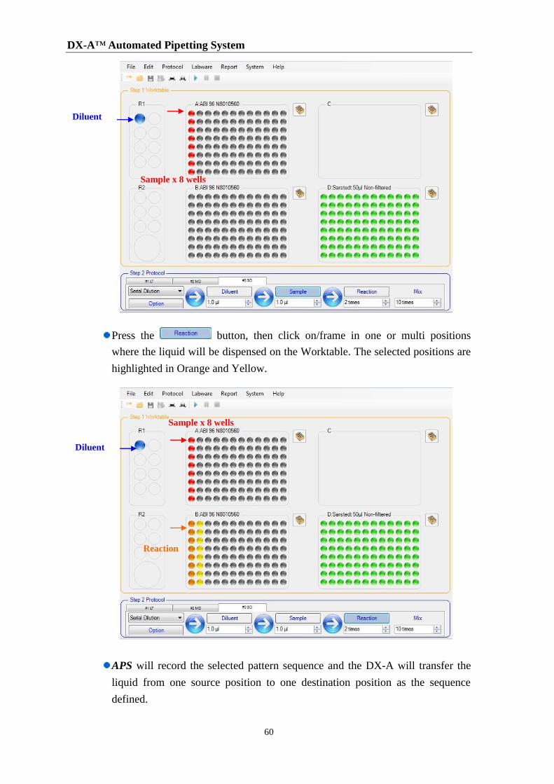
Press the button, then click on/frame in one or multi positions
where the liquid will be dispensed on the Worktable. The selected positions are
highlighted in Orange and Yellow.
APS will record the selected pattern sequence and the DX-A will transfer the
liquid from one source position to one destination position as the sequence
defined.
Diluent
Sample x 8 wells
Diluent
Sample x 8 wells
Reaction
6 Operation
61
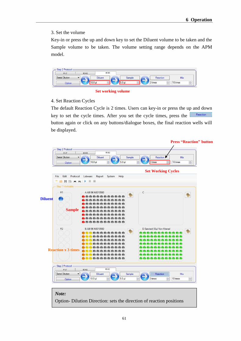
3. Set the volume
Key-in or press the up and down key to set the Diluent volume to be taken and the
Sample volume to be taken. The volume setting range depends on the APM
model.
4. Set Reaction Cycles
The default Reaction Cycle is 2 times. Users can key-in or press the up and down
key to set the cycle times. After you set the cycle times, press the
button again or click on any buttons/dialogue boxes, the final reaction wells will
be displayed.
Note:
Option- Dilution Direction: sets the direction of reaction positions
Set working volume
Diluent
Sample
Reaction x 3 times
Press “Reaction” button
Set Working Cycles
DX-A™ Automated Pipetting System
62
Select “ Horizontal (Default)”
- The default dilution direction is Horizontal. If Horizontal is
selected, the reaction wells will shift from left to right →.
For 96 well plate, the reaction cycle range is from 2 to 12 times.
For 384 well plate, the reaction cycle range is from 2 to 12 times.
Select “ Vertical ”
Users can change the dilution direction to Vertical. If Vertical is
selected, the reaction wells will shift from top to down↓.
For 96 well plate, the reaction cycle range is from 2 to 8 times.
For 384 well plate, the reaction cycle range is from 2 to 12 times.
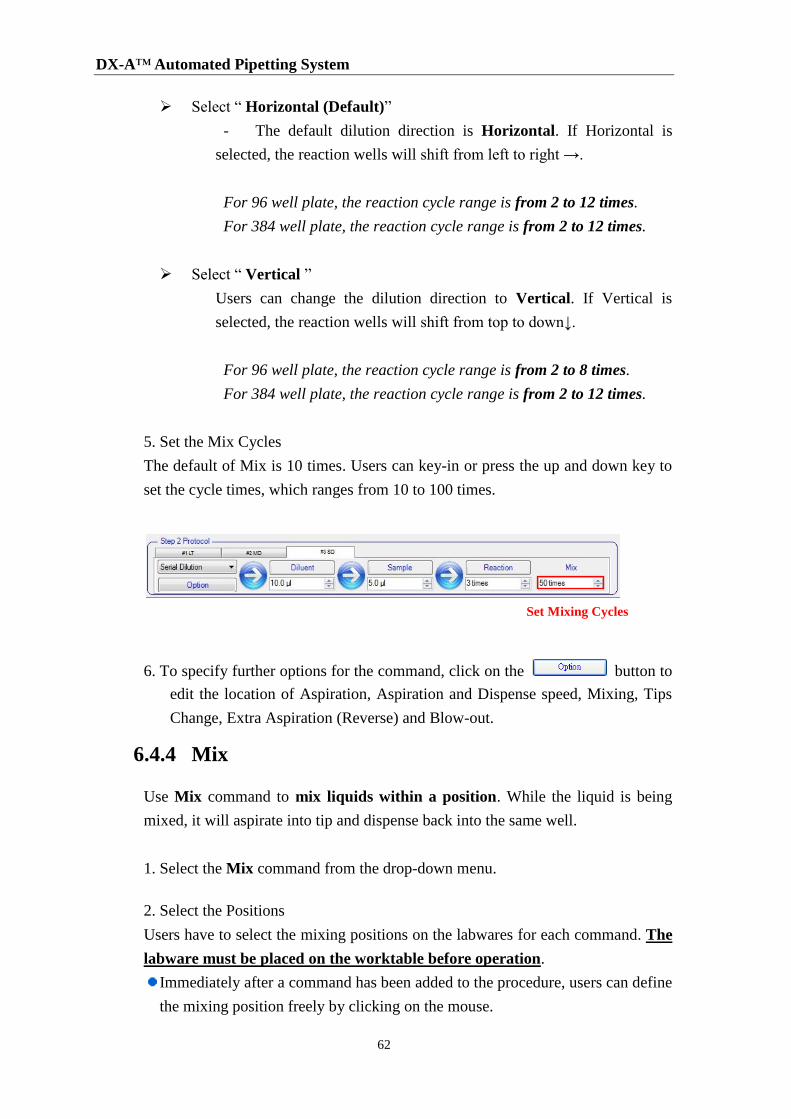
5. Set the Mix Cycles
The default of Mix is 10 times. Users can key-in or press the up and down key to
set the cycle times, which ranges from 10 to 100 times.
6. To specify further options for the command, click on the button to
edit the location of Aspiration, Aspiration and Dispense speed, Mixing, Tips
Change, Extra Aspiration (Reverse) and Blow-out.
6.4.4 Mix
Use Mix command to mix liquids within a position. While the liquid is being
mixed, it will aspirate into tip and dispense back into the same well.
1. Select the Mix command from the drop-down menu.
2. Select the Positions
Users have to select the mixing positions on the labwares for each command. The
labware must be placed on the worktable before operation.
Immediately after a command has been added to the procedure, users can define
the mixing position freely by clicking on the mouse.
Set Mixing Cycles
6 Operation
63
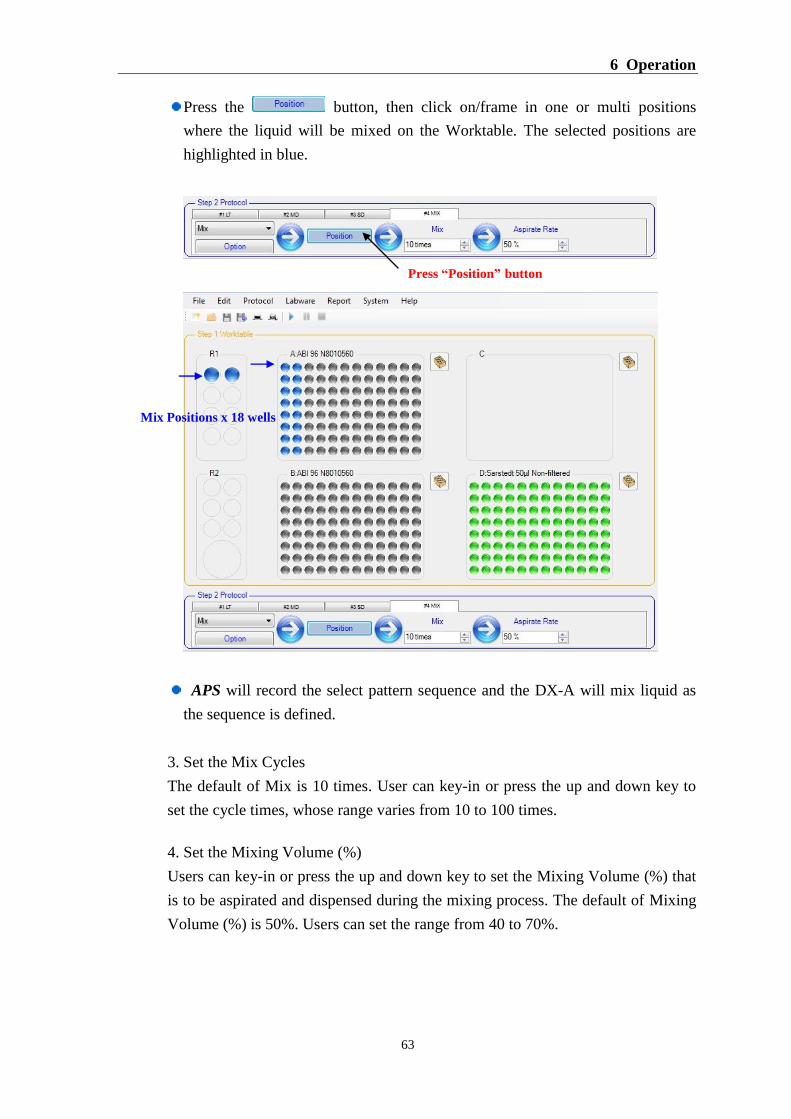
Press the button, then click on/frame in one or multi positions
where the liquid will be mixed on the Worktable. The selected positions are
highlighted in blue.
APS will record the select pattern sequence and the DX-A will mix liquid as
the sequence is defined.
3. Set the Mix Cycles
The default of Mix is 10 times. User can key-in or press the up and down key to
set the cycle times, whose range varies from 10 to 100 times.
4. Set the Mixing Volume (%)
Users can key-in or press the up and down key to set the Mixing Volume (%) that
is to be aspirated and dispensed during the mixing process. The default of Mixing
Volume (%) is 50%. Users can set the range from 40 to 70%.
Press “Position” button
Mix Positions x 18 wells
DX-A™ Automated Pipetting System
64
Upon setting the Mixing Volume (%), APS will automatically add the total
dispensed liquid volume of the selected positions. Then, calculate the Mixing
Volume that is to be aspirated and dispensed.
Total dispensed liquid volume of a position x Mixing Volume (%) =
Mixing Volume
The Mixing Volume should be ≦ the APM maximum aspiration volume
(APM50Max is 50 µl, APM200 Max is 200 µl). If the Mixing Volume is ≧ the
APM maximum aspiration volume, then the APM will aspirate and
dispense the maximum volume.
5. To specify further options for the command, click on the button to
edit the location of Aspiration, Aspiration and Dispense speed, Mixing, Tips
Change, Extra Aspiration (Reverse) and Blow-out.
6.4.5 Hold
The Hold command specifies a defined pause before the next command. The
APS will continue automatically after the hold time has lapsed or wait users to
press the Go On button to continue to the next command.
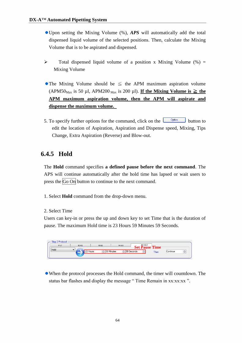
1. Select Hold command from the drop-down menu.
2. Select Time
Users can key-in or press the up and down key to set Time that is the duration of
pause. The maximum Hold time is 23 Hours 59 Minutes 59 Seconds.
When the protocol processes the Hold command, the timer will countdown. The
status bar flashes and display the message “ Time Remain in xx:xx:xx ”.
Set Pause Time
6 Operation
65
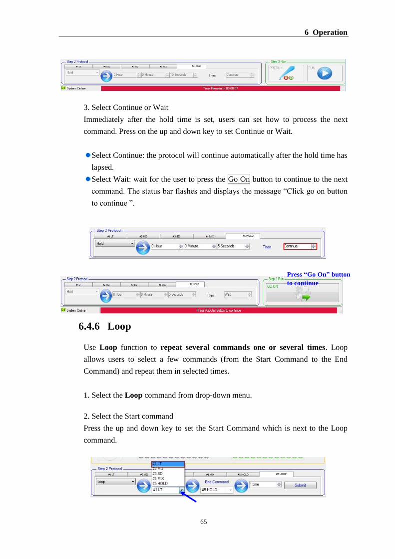
3. Select Continue or Wait
Immediately after the hold time is set, users can set how to process the next
command. Press on the up and down key to set Continue or Wait.
Select Continue: the protocol will continue automatically after the hold time has
lapsed.
Select Wait: wait for the user to press the Go On button to continue to the next
command. The status bar flashes and displays the message “Click go on button
to continue ”.
6.4.6 Loop
Use Loop function to repeat several commands one or several times. Loop
allows users to select a few commands (from the Start Command to the End
Command) and repeat them in selected times.
1. Select the Loop command from drop-down menu.
2. Select the Start command
Press the up and down key to set the Start Command which is next to the Loop
command.
Press “Go On” button
to continue
DX-A™ Automated Pipetting System
66
Users must set the End command as the command before the Loop command.
For example: When the Loop command is in the sixth steps #6 Loop, the
End command must be the fifth steps.
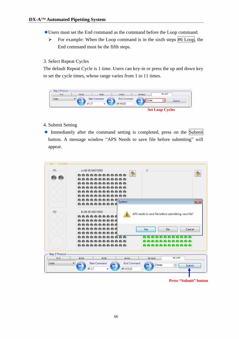
3. Select Repeat Cycles
The default Repeat Cycle is 1 time. Users can key-in or press the up and down key
to set the cycle times, whose range varies from 1 to 11 times.
4. Submit Setting
Immediately after the command setting is completed, press on the Submit
button. A message window “APS Needs to save file before submtting” will
appear.
Set Loop Cycles
Press “Submit” button
6 Operation
67
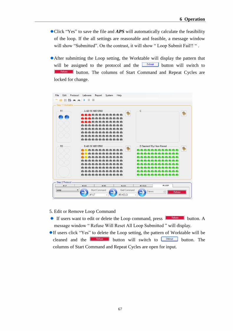
Click “Yes” to save the file and APS will automatically calculate the feasibility
of the loop. If the all settings are reasonable and feasible, a message window
will show “Submitted”. On the contrast, it will show “ Loop Submit Fail!! “ .
After submitting the Loop setting, the Worktable will display the pattern that
will be assigned to the protocol and the button will switch to
button. The columns of Start Command and Repeat Cycles are
locked for change.
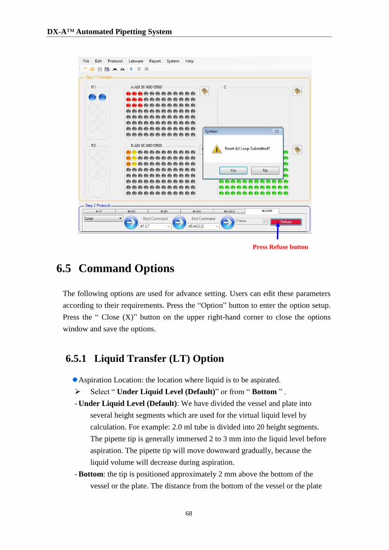
5. Edit or Remove Loop Command
If users want to edit or delete the Loop command, press button. A
message window “ Refuse Will Reset All Loop Submitted ” will display.
If users click “Yes” to delete the Loop setting, the pattern of Worktable will be
cleaned and the button will switch to button. The
columns of Start Command and Repeat Cycles are open for input.
DX-A™ Automated Pipetting System
68
6.5 Command Options
The following options are used for advance setting. Users can edit these parameters
according to their requirements. Press the “Option” button to enter the option setup.
Press the “ Close (X)” button on the upper right-hand corner to close the options
window and save the options.
6.5.1 Liquid Transfer (LT) Option
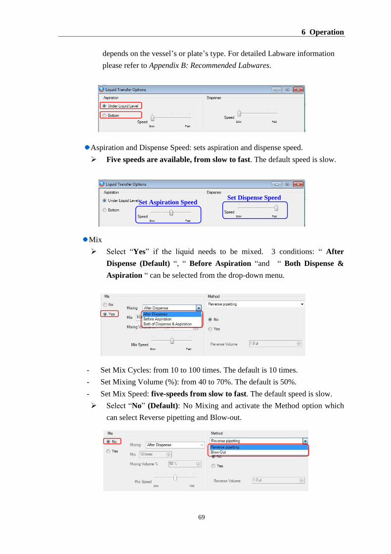
Aspiration Location: the location where liquid is to be aspirated.
Select “ Under Liquid Level (Default)” or from “ Bottom ” .
- Under Liquid Level (Default): We have divided the vessel and plate into
several height segments which are used for the virtual liquid level by
calculation. For example: 2.0 ml tube is divided into 20 height segments.
The pipette tip is generally immersed 2 to 3 mm into the liquid level before
aspiration. The pipette tip will move downward gradually, because the
liquid volume will decrease during aspiration.
- Bottom: the tip is positioned approximately 2 mm above the bottom of the
vessel or the plate. The distance from the bottom of the vessel or the plate
Press Refuse button
6 Operation
69
depends on the vessel’s or plate’s type. For detailed Labware information
please refer to Appendix B: Recommended Labwares.
Aspiration and Dispense Speed: sets aspiration and dispense speed.
Five speeds are available, from slow to fast. The default speed is slow.
Mix
Select “Yes” if the liquid needs to be mixed. 3 conditions: “ After
Dispense (Default) “, “ Before Aspiration “and “ Both Dispense &
Aspiration “ can be selected from the drop-down menu.
- Set Mix Cycles: from 10 to 100 times. The default is 10 times.
- Set Mixing Volume (%): from 40 to 70%. The default is 50%.
- Set Mix Speed: five-speeds from slow to fast. The default speed is slow.
Select “No” (Default): No Mixing and activate the Method option which
can select Reverse pipetting and Blow-out.
Set Aspiration Speed Set Dispense Speed

DX-A™ Automated Pipetting System
70
Tip Change: set when to change tip
Select “Yes” to specify when the tips are to be changed. 3 conditions:
“ Before Each Aspiration (Default) “, “ When A Command Finishes
“ and “ After xx Aspirations “ are available.
Select “No”: Not to change tips. This option will affect the accuracy of the
pipetting.
Method: If you select “No” under the Mix option, the Method option will
become active. You can select “ Reverse pipetting “ or “ Blow-out “.
6 Operation
71
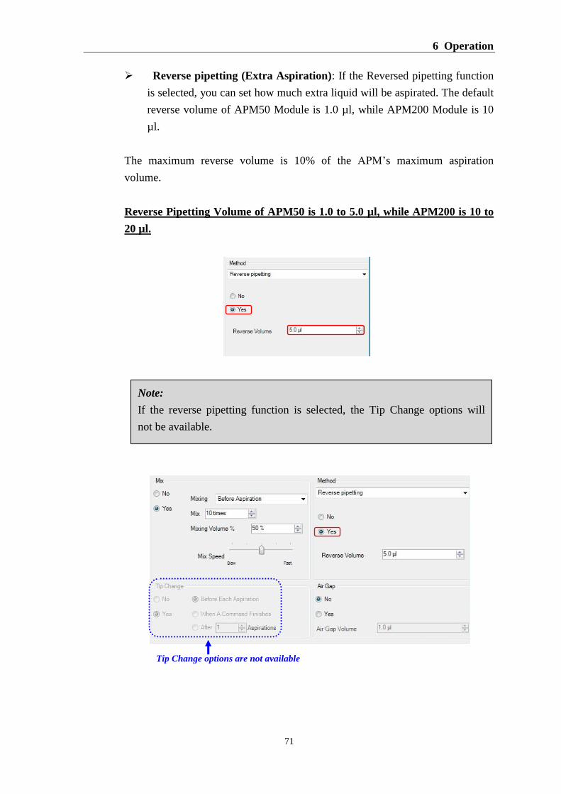
Reverse pipetting (Extra Aspiration): If the Reversed pipetting function
is selected, you can set how much extra liquid will be aspirated. The default
reverse volume of APM50 Module is 1.0 µl, while APM200 Module is 10
µl.
The maximum reverse volume is 10% of the APM’s maximum aspiration
volume.
Reverse Pipetting Volume of APM50 is 1.0 to 5.0 µl, while APM200 is 10 to
20 µl.
Note:
If the reverse pipetting function is selected, the Tip Change options will
not be available.
Tip Change options are not available
DX-A™ Automated Pipetting System
72
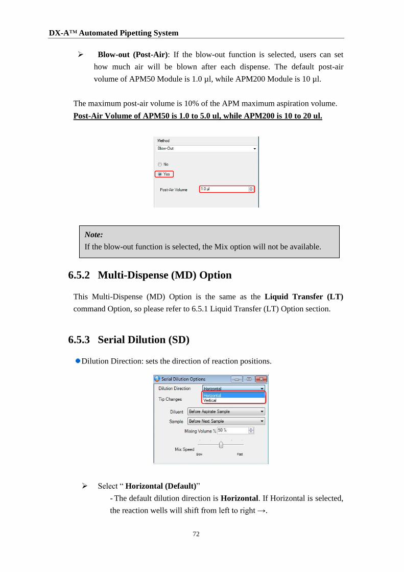
Blow-out (Post-Air): If the blow-out function is selected, users can set
how much air will be blown after each dispense. The default post-air
volume of APM50 Module is 1.0 µl, while APM200 Module is 10 µl.
The maximum post-air volume is 10% of the APM maximum aspiration volume.
Post-Air Volume of APM50 is 1.0 to 5.0 ul, while APM200 is 10 to 20 ul.
6.5.2 Multi-Dispense (MD) Option
This Multi-Dispense (MD) Option is the same as the Liquid Transfer (LT)
command Option, so please refer to 6.5.1 Liquid Transfer (LT) Option section.
6.5.3 Serial Dilution (SD)
Dilution Direction: sets the direction of reaction positions.
Select “ Horizontal (Default)”
- The default dilution direction is Horizontal. If Horizontal is selected,
the reaction wells will shift from left to right →.
Note:
If the blow-out function is selected, the Mix option will not be available.
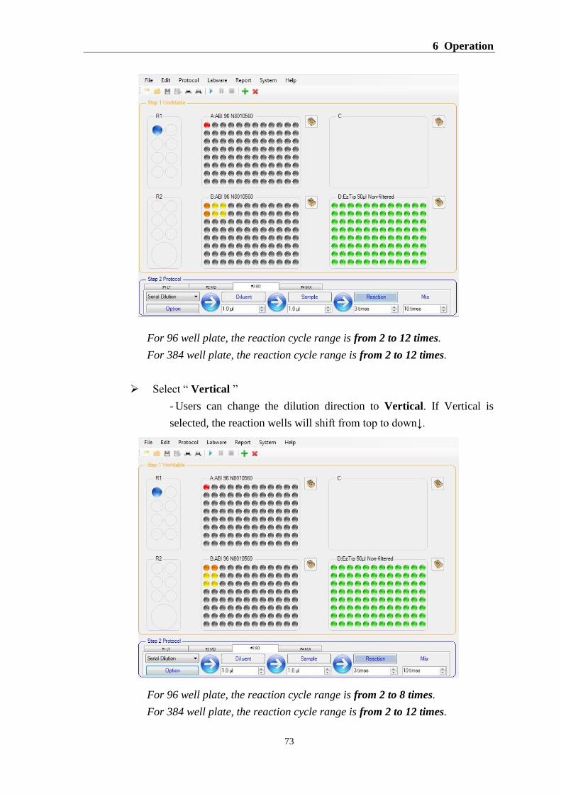
6 Operation
73
For 96 well plate, the reaction cycle range is from 2 to 12 times.
For 384 well plate, the reaction cycle range is from 2 to 12 times.
Select “ Vertical ”
- Users can change the dilution direction to Vertical. If Vertical is
selected, the reaction wells will shift from top to down↓.
For 96 well plate, the reaction cycle range is from 2 to 8 times.
For 384 well plate, the reaction cycle range is from 2 to 12 times.

DX-A™ Automated Pipetting System
74
Tip Change: sets when to change tip
For Buffer/Diluent: select change tip “ Before Aspirate Sample
(Default)” or “ Each Aspiration ”.
-The default Tip Changes for Buffer/Diluent is Before Aspirate Sample.
If option is selected, APM will use the same tip to aspirate and dispense
Buffer/Diluent. It can save the usage of tip, but the accuracy may decrease.
-Users can select Each Aspiration; APM will use new tips before each
aspiration. If the buffer is viscous, we suggest to change the tip before
each aspiration to increase the accuracy and precision.
For example: select Tip Changes> “ Before Next Sample (Default)” or
“ Each Dispense ”.
-The default tip change for Sample is Before Next Sample. If users select
the option, APM takes sample #1 dispense sample #1 to reaction well
#1 Mix take the diluted sample from reaction well #1 and dispense
to reaction well #2 Mix change tip before APM takes sample #2
-If users select “Each Dispense”, APM will use new tip after each
dispense.
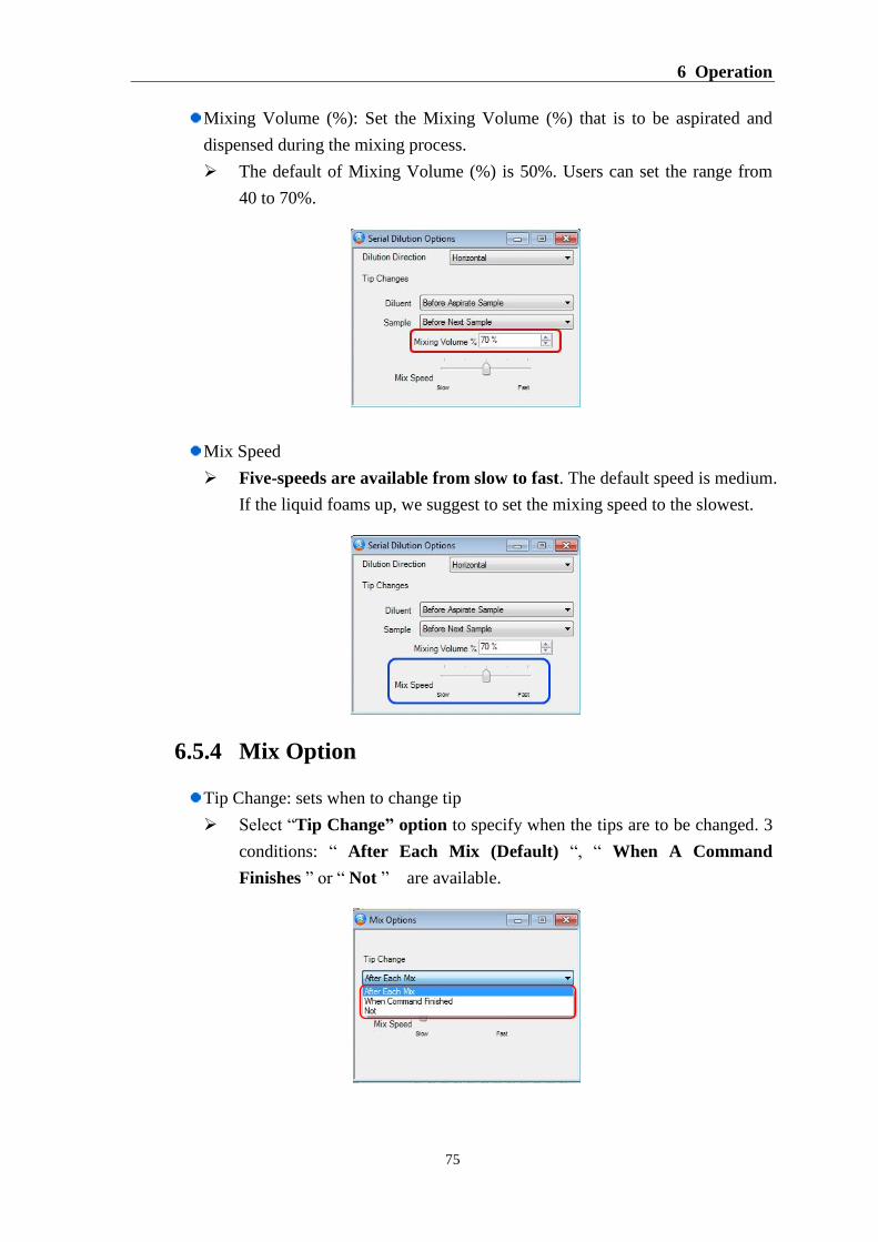
6 Operation
75
Mixing Volume (%): Set the Mixing Volume (%) that is to be aspirated and
dispensed during the mixing process.
The default of Mixing Volume (%) is 50%. Users can set the range from
40 to 70%.
Mix Speed
Five-speeds are available from slow to fast. The default speed is medium.
If the liquid foams up, we suggest to set the mixing speed to the slowest.
6.5.4 Mix Option
Tip Change: sets when to change tip
Select “Tip Change” option to specify when the tips are to be changed. 3
conditions: “ After Each Mix (Default) “, “ When A Command
Finishes ” or “ Not ” are available.
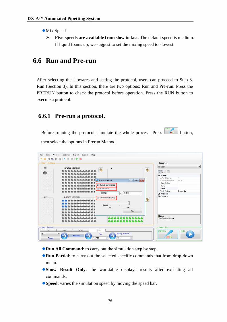
DX-A™ Automated Pipetting System
76
Mix Speed
Five-speeds are available from slow to fast. The default speed is medium.
If liquid foams up, we suggest to set the mixing speed to slowest.
6.6 Run and Pre-run
After selecting the labwares and setting the protocol, users can proceed to Step 3.
Run (Section 3). In this section, there are two options: Run and Pre-run. Press the
PRERUN button to check the protocol before operation. Press the RUN button to
execute a protocol.
6.6.1 Pre-run a protocol.
Before running the protocol, simulate the whole process. Press button,
then select the options in Prerun Method.
Run All Command: to carry out the simulation step by step.
Run Partial: to carry out the selected specific commands that from drop-down
menu.
Show Result Only: the worktable displays results after executing all
commands.
Speed: varies the simulation speed by moving the speed bar.
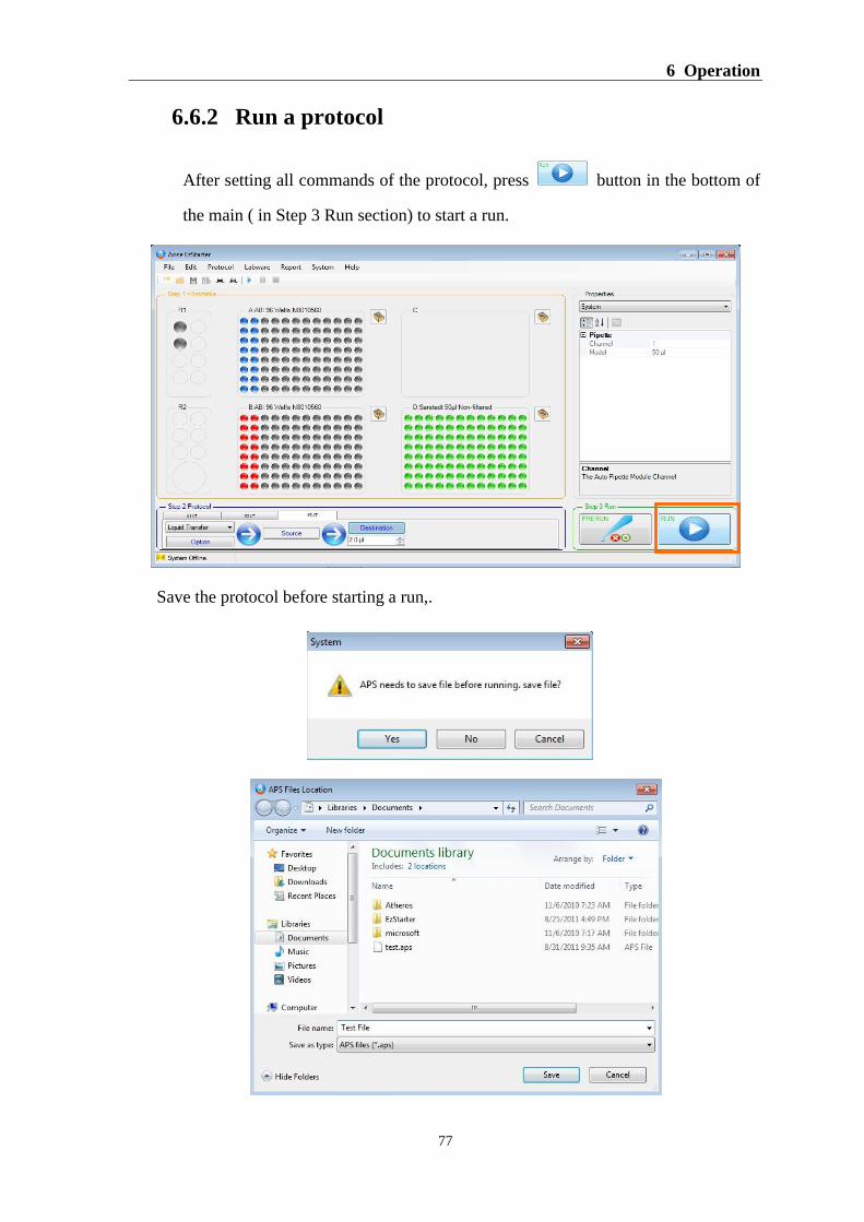
6 Operation
77
6.6.2 Run a protocol
After setting all commands of the protocol, press button in the bottom of
the main ( in Step 3 Run section) to start a run.
Save the protocol before starting a run,.
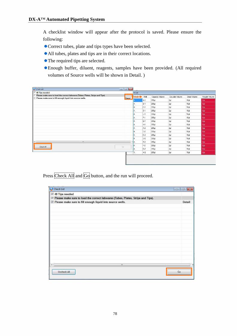
DX-A™ Automated Pipetting System
78
A checklist window will appear after the protocol is saved. Please ensure the
following:
Correct tubes, plate and tips types have been selected.
All tubes, plates and tips are in their correct locations.
The required tips are selected.
Enough buffer, diluent, reagents, samples have been provided. (All required
volumes of Source wells will be shown in Detail. )
Press Check All and Go button, and the run will proceed.
7 Maintenance
79
7 Maintenance
DX-A is a robust, reliable instrument that requires minimal maintenance. Its enclosure
protects it from dust and foreign objects, thus its motion control components, such as
linear guide, belt and motor, require almost no maintenance.
The rest of the components, such as APM, Adapters, worktable can be cleaned,
disinfected or serviced as described in the sections below.
7.1 Cleaning the Worktable
Use a soft, lint-free cloth and mild detergents, such as 5% bleach, or 70% ethanol to
clean the worktable.
7.2 Cleaning the Automated Pipetting Module (APM)
The housing of APM module is made of ABS plastic material. To clean the APM,
remove the APM from the Z-axis platform first. Use a soft, lint-free cloth and mild
detergents, such as 5% bleach, or 70% ethanol to clean the APM.
7.3 Servicing the Automated Pipetting Module
(APM)
To maintain the Accuracy and Precision, such as the hand-held manual or electronic
pipettes, return the APM to TBG or its service partners for annual calibration service.
The fuse is located in the power socket module, just below the power connector.
Replace the fuse if the unit does not turn on when the power switch is turned on.
Caution!
UV radiation will damage the exposed cables, APM and motion control parts.
Caution!
APM can’t be autoclaved.
DX-A™ Automated Pipetting System
80
7.4 Cleaning the Adapters
Use a soft, lint-free cloth and mild detergents, such as 5% bleach, or 70% ethanol to
clean the surface of Adapters. The Adapters, except the CoolBlocks, can be
autoclaved for 20 minutes at 121 ºC and 1 bar pressure.
7.5 Replacing a Fuse
The fuse is located in the power socket module, just below the power connector. If
the unit does not turn on when the power switch is turned on, then replace the fuse.
To replace the fuse:
1. Disconnect the power cord from the unit.
2. Remove the fuse drawer with a small-blade screwdriver.
3. Pull the fuse out of the fuse socket and replace the fuse with the correct current
rating: 3.5A, 5 x 20mm, Glass Tube.
4. Reinsert the fuse into the fuse socket and the fuse drawer.

DX-A ™ Automated Pipetting System 8 Troubleshooting
81
8 Troubleshooting
Problem Cause Action
Power failure. Blown fuse. Replace a new fuse.
Droplets left inside the tip. Unsuitable tip. Use Beckman Biomek® 3000
compatible tips.
Leakage or volume too small. Worn-out internal O-ring. Replace the defect internal
O-ring with a new one.
Failure to aspirate. The lower manifold is not
correctly attached.
Detach and reassemble
Foreign material blocking the
hole at bottom of the cone.
Use MIX mode and distilled
water to wash.
Piston movement is blocked. Lubricate piston.
8.1 Error Messages
Code Message Cause Remedy
1001 Not an existing file!! Original protocol file has
been deleted or moved. Check file location.
0001 System Initial Error Initial APS system failure Is system storage space
enough?
1002 Not a APS protocol format
file File damaged. Check protocol file format.
0002 Protocol has wrong APM
selection!!
Protocol has the wrong
selection with connected
APM module.
Change APM module or
recreate a new protocol for
current APM module.
2001 Connection time out
error!!
No connection /w APS when
protocol is running.
Check USB/RS-232 connection
cable.
0003 APM NOT
AVAILABLE!!
Wrong APM module during
software calibration. Check APM's serial number.
0004 APS NOT AVAILABLE!! No connection /w APS when
system is initialized.
Check USB/RS-232 connection
cable or reset APS.
2002 Loop Submission Failure!! Microplate layout cannot do
loop function Check microplate layout.
9901 Printing Error!! Check
Printer.
PC has no connection /w
printer. Check printer connection.
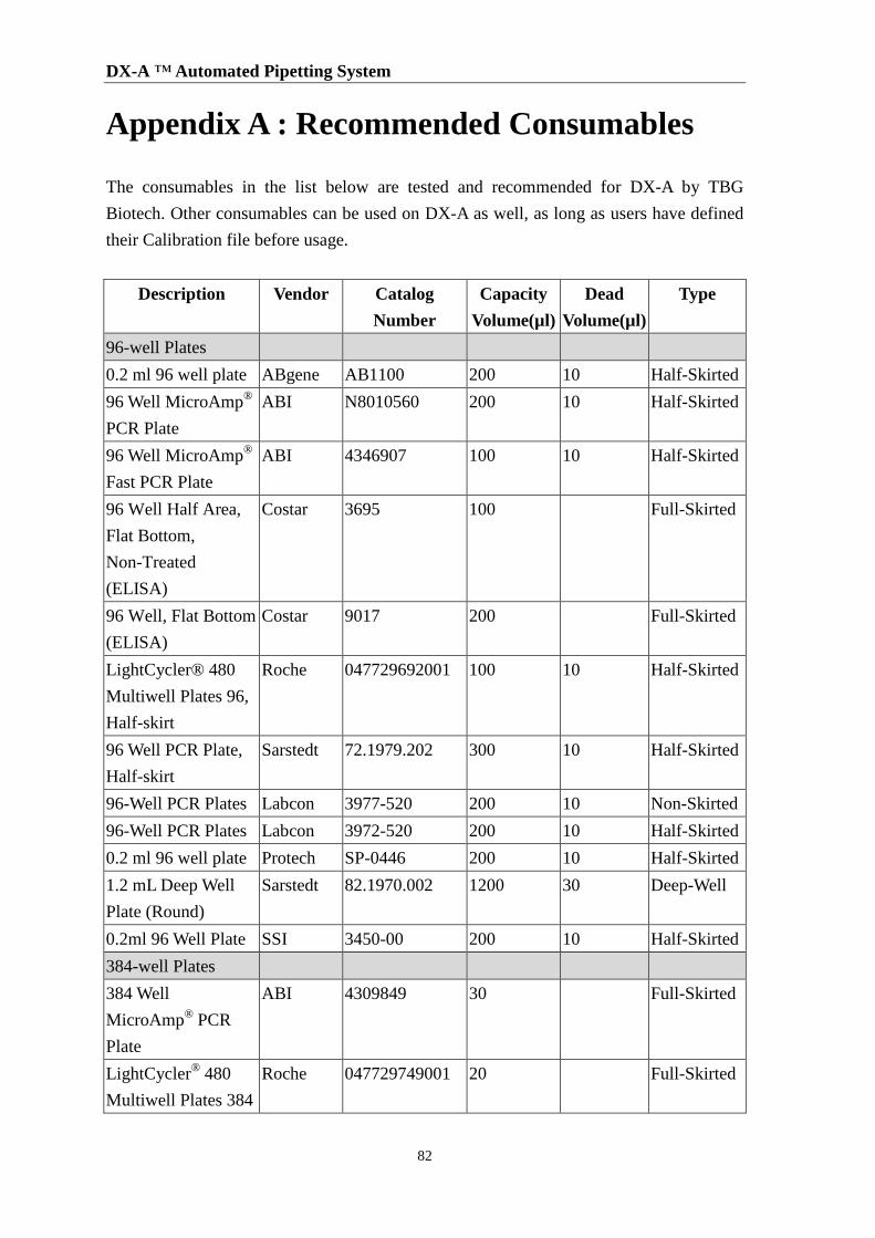
DX-A ™ Automated Pipetting System
82
Appendix A : Recommended Consumables
The consumables in the list below are tested and recommended for DX-A by TBG
Biotech. Other consumables can be used on DX-A as well, as long as users have defined
their Calibration file before usage.
Description Vendor Catalog
Number
Capacity
Volume(µl)
Dead
Volume(µl)
Type
96-well Plates
0.2 ml 96 well plate ABgene AB1100 200 10 Half-Skirted
96 Well MicroAmp®
PCR Plate
ABI N8010560 200 10 Half-Skirted
96 Well MicroAmp®
Fast PCR Plate
ABI 4346907 100 10 Half-Skirted
96 Well Half Area,
Flat Bottom,
Non-Treated
(ELISA)
Costar 3695 100 Full-Skirted
96 Well, Flat Bottom
(ELISA)
Costar 9017 200 Full-Skirted
LightCycler® 480
Multiwell Plates 96,
Half-skirt
Roche 047729692001 100 10 Half-Skirted
96 Well PCR Plate,
Half-skirt
Sarstedt 72.1979.202 300 10 Half-Skirted
96-Well PCR Plates Labcon 3977-520 200 10 Non-Skirted
96-Well PCR Plates Labcon 3972-520 200 10 Half-Skirted
0.2 ml 96 well plate Protech SP-0446 200 10 Half-Skirted
1.2 mL Deep Well
Plate (Round)
Sarstedt 82.1970.002 1200 30 Deep-Well
0.2ml 96 Well Plate SSI 3450-00 200 10 Half-Skirted
384-well Plates
384 Well
MicroAmp® PCR
Plate
ABI 4309849 30 Full-Skirted
LightCycler® 480
Multiwell Plates 384
Roche 047729749001 20 Full-Skirted
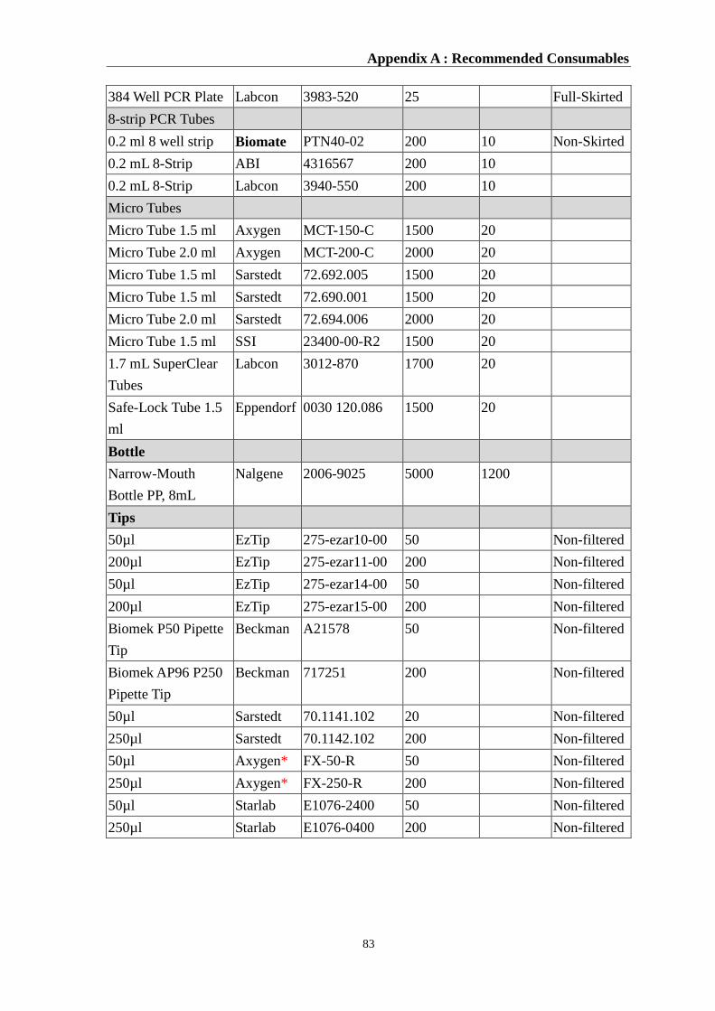
Appendix A : Recommended Consumables
83
384 Well PCR Plate Labcon 3983-520 25 Full-Skirted
8-strip PCR Tubes
0.2 ml 8 well strip Biomate PTN40-02 200 10 Non-Skirted
0.2 mL 8-Strip ABI 4316567 200 10
0.2 mL 8-Strip Labcon 3940-550 200 10
Micro Tubes
Micro Tube 1.5 ml Axygen MCT-150-C 1500 20
Micro Tube 2.0 ml Axygen MCT-200-C 2000 20
Micro Tube 1.5 ml Sarstedt 72.692.005 1500 20
Micro Tube 1.5 ml Sarstedt 72.690.001 1500 20
Micro Tube 2.0 ml Sarstedt 72.694.006 2000 20
Micro Tube 1.5 ml SSI 23400-00-R2 1500 20
1.7 mL SuperClear
Tubes
Labcon 3012-870 1700 20
Safe-Lock Tube 1.5
ml
Eppendorf 0030 120.086 1500 20
Bottle
Narrow-Mouth
Bottle PP, 8mL
Nalgene 2006-9025 5000 1200
Tips
50µl EzTip 275-ezar10-00 50 Non-filtered
200µl EzTip 275-ezar11-00 200 Non-filtered
50µl EzTip 275-ezar14-00 50 Non-filtered
200µl EzTip 275-ezar15-00 200 Non-filtered
Biomek P50 Pipette
Tip
Beckman A21578 50 Non-filtered
Biomek AP96 P250
Pipette Tip
Beckman 717251 200 Non-filtered
50µl Sarstedt 70.1141.102 20 Non-filtered
250µl Sarstedt 70.1142.102 200 Non-filtered
50µl Axygen* FX-50-R 50 Non-filtered
250µl Axygen* FX-250-R 200 Non-filtered
50µl Starlab E1076-2400 50 Non-filtered
250µl Starlab E1076-0400 200 Non-filtered
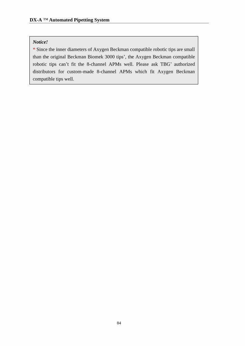
DX-A ™ Automated Pipetting System
84
Notice!
* Since the inner diameters of Axygen Beckman compatible robotic tips are small
than the original Beckman Biomek 3000 tips’, the Axygen Beckman compatible
robotic tips can’t fit the 8-channel APMs well. Please ask TBG’ authorized
distributors for custom-made 8-channel APMs which fit Axygen Beckman
compatible tips well.
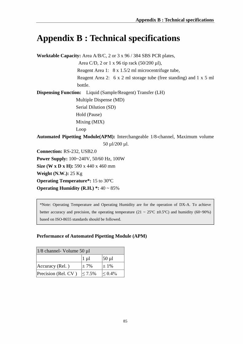
Appendix B : Technical specifications
85
Appendix B : Technical specifications
Worktable Capacity: Area A/B/C, 2 or 3 x 96 / 384 SBS PCR plates,
Area C/D, 2 or 1 x 96 tip rack (50/200 µl),
Reagent Area 1: 8 x 1.5/2 ml microcentrifuge tube,
Reagent Area 2: 6 x 2 ml storage tube (free standing) and 1 x 5 ml
bottle.
Dispensing Function: Liquid (Sample/Reagent) Transfer (LH)
Multiple Dispense (MD)
Serial Dilution (SD)
Hold (Pause)
Mixing (MIX)
Loop
Automated Pipetting Module(APM): Interchangeable 1/8-channel, Maximum volume
50 µl/200 µl.
Connection: RS-232, USB2.0
Power Supply: 100~240V, 50/60 Hz, 100W
Size (W x D x H): 590 x 440 x 460 mm
Weight (N.W.): 25 Kg
Operating Temperature*: 15 to 30ºC
Operating Humidity (R.H.) *: 40 ~ 85%
Performance of Automated Pipetting Module (APM)
1/8 channel- Volume 50 µl
1 µl 50 µl
Accuracy (Rel. ) ± 7% ± 1%
Precision (Rel. CV ) ≤ 7.5% ≤ 0.4%
*Note: Operating Temperature and Operating Humidity are for the operation of DX-A. To achieve
better accuracy and precision, the operating temperature (21 ~ 25ºC ±0.5ºC) and humidity (60~90%)
based on ISO-8655 standards should be followed.
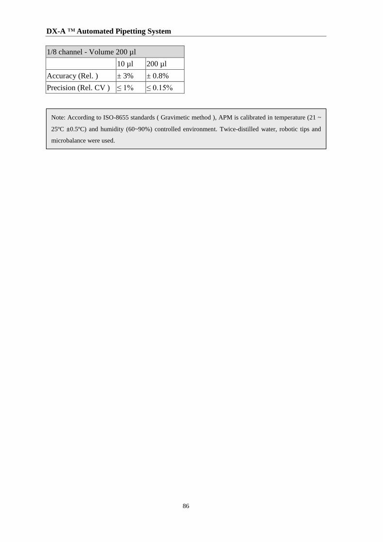
DX-A ™ Automated Pipetting System
86
1/8 channel - Volume 200 µl
10 µl 200 µl
Accuracy (Rel. ) ± 3% ± 0.8%
Precision (Rel. CV ) ≤ 1% ≤ 0.15%
Note: According to ISO-8655 standards ( Gravimetic method ), APM is calibrated in temperature (21 ~
25ºC ±0.5ºC) and humidity (60~90%) controlled environment. Twice-distilled water, robotic tips and
microbalance were used.
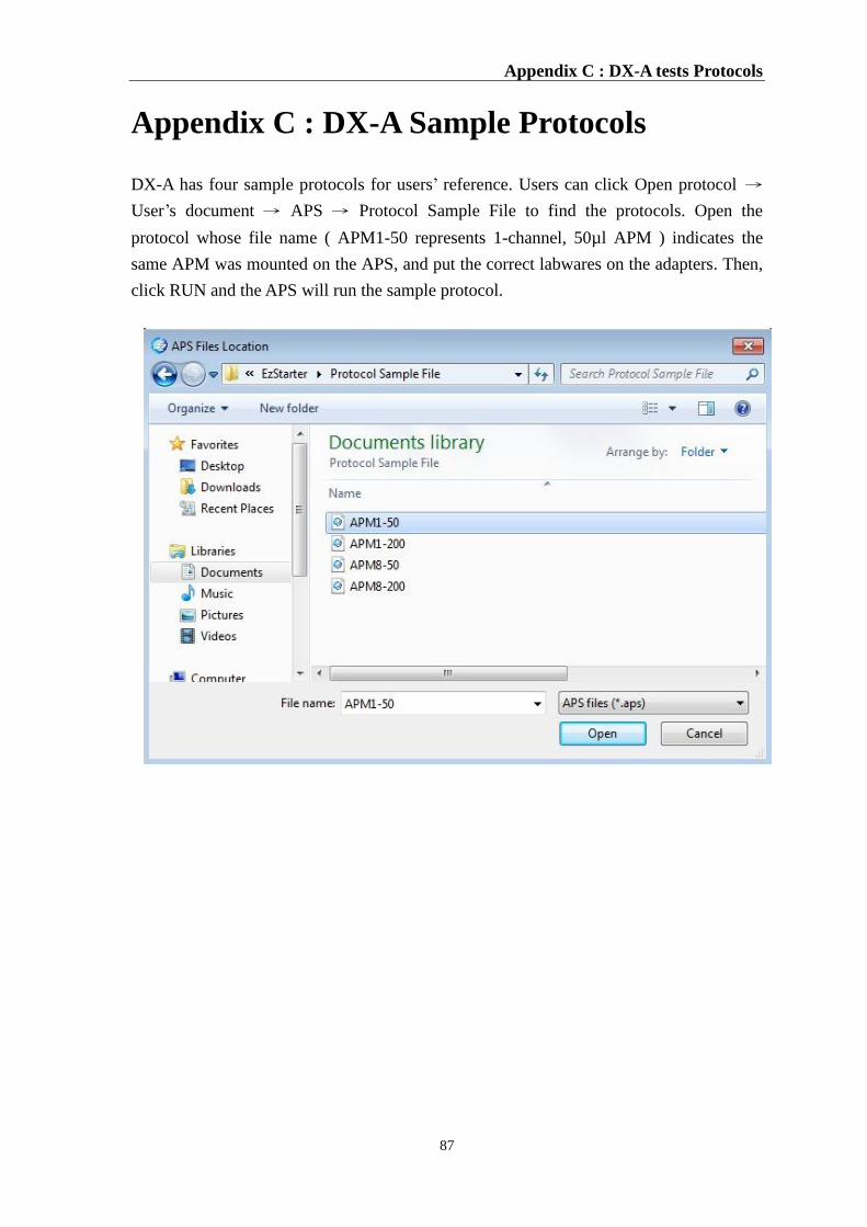
Appendix C : DX-A tests Protocols
87
Appendix C : DX-A Sample Protocols
DX-A has four sample protocols for users’ reference. Users can click Open protocol →
User’s document → APS → Protocol Sample File to find the protocols. Open the
protocol whose file name ( APM1-50 represents 1-channel, 50µl APM ) indicates the
same APM was mounted on the APS, and put the correct labwares on the adapters. Then,
click RUN and the APS will run the sample protocol.
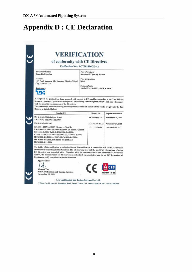
DX-A ™ Automated Pipetting System
88
Appendix D : CE Declaration
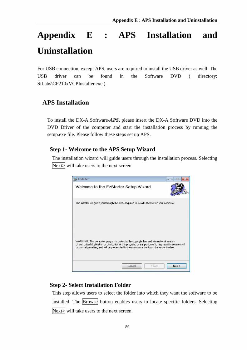
Appendix E : APS Installation and Uninstallation
89
Appendix E : APS Installation and
Uninstallation
For USB connection, except APS, users are required to install the USB driver as well. The
USB driver can be found in the Software DVD ( directory:
SiLabs\CP210xVCPInstaller.exe ).
APS Installation
To install the DX-A Software-APS, please insert the DX-A Software DVD into the
DVD Driver of the computer and start the installation process by running the
setup.exe file. Please follow these steps set up APS.
Step 1- Welcome to the APS Setup Wizard
The installation wizard will guide users through the installation process. Selecting
Next> will take users to the next screen.
Step 2- Select Installation Folder
This step allows users to select the folder into which they want the software to be
installed. The Browse button enables users to locate specific folders. Selecting
Next> will take users to the next screen.
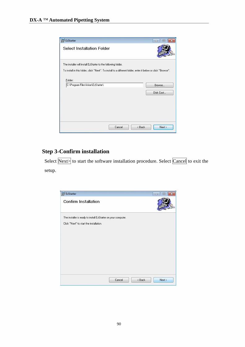
DX-A ™ Automated Pipetting System
90
Step 3-Confirm installation
Select Next> to start the software installation procedure. Select Cancel to exit the
setup.
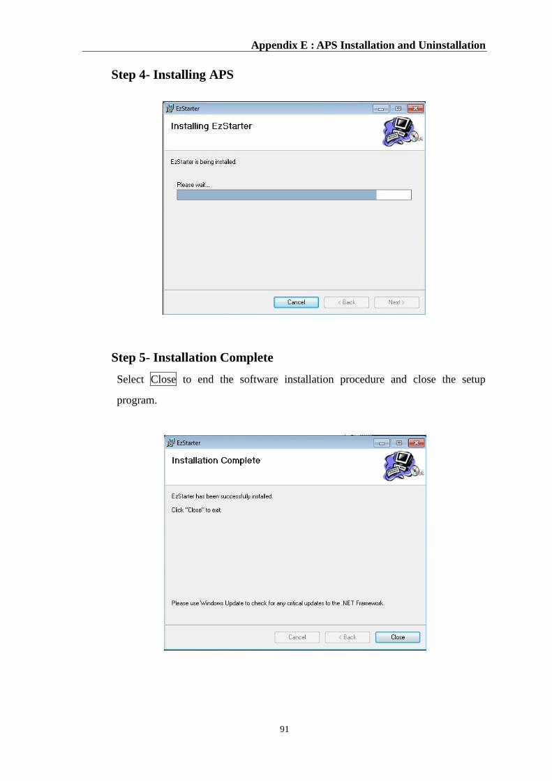
Appendix E : APS Installation and Uninstallation
91
Step 4- Installing APS
Step 5- Installation Complete
Select Close to end the software installation procedure and close the setup
program.
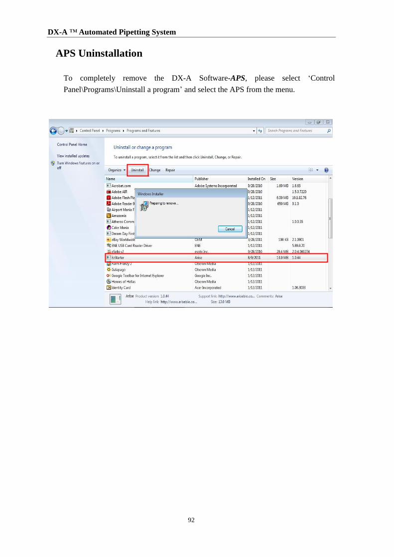
DX-A ™ Automated Pipetting System
92
APS Uninstallation
To completely remove the DX-A Software-APS, please select ‘Control
Panel\Programs\Uninstall a program’ and select the APS from the menu.

Printed in Taiwan
P/N: 401-aps401-10
2015 Nov.
TBG Biotechnology Corp.
13F., No.237, Sec.1, Datong Rd., Xizhi Dist., New Taipei City, Taiwan, 22161
TEL: +886-2-7741-7777 FAX: +886-2-7741-7700
E-mail: [email protected].
Web Site: www.TexasBioGene.com.