Embed Size (px)
Citation preview

Operator’s Manual
DXC100A Differential Probe Pair

© 2017 Teledyne LeCroy, Inc. All rights reserved.
Unauthorized duplication of Teledyne LeCroy documentation materials other than for internal sales and distribution purposes is strictly prohibited. Customers are permitted to duplicate and distribute Teledyne LeCroy documentation for internal training purposes.
Teledyne LeCroy is a registered trademark of Teledyne LeCroy, Inc. Other product or brand names are trademarks or requested trademarks of their respective holders. Information in this publication supersedes all earlier versions. Specifications are subject to change without notice.
928334-00 Rev A April, 2017

Operator’s Manual
928334-00 Rev A 1
Safety Instructions This section contains instructions that must be observed to keep this oscilloscope accessory operating in a correct and safe condition. You are required to follow generally accepted safety procedures in addition to the precautions specified in this section. The overall safety of any system incorporating this accessory is the responsibility of the assembler of the system.
Symbols These symbols may appear on the probe body or in this manual to alert you to important safety considerations.
High Voltage, risk of electric shock.
CAUTION of potential for damage to probe or instrument it is connected to, or WARNING of potential bodily injury. Attend to the accompanying information to protect against personal injury or damage. Do not proceed until conditions are fully understood and met.
ELECTROSTATIC DISCHARGE (ESD) HAZARD. Susceptible to damage if anti-static measures are not taken.
DOUBLE INSULATION
PROTECTIVE (EARTH) TERMINAL

DXC100A Differential Probe Pair
2
Precautions Connect and disconnect properly. Connect probe to the measurement instrument before connecting the test leads to a circuit/signal being tested.
Use only within operational environment listed. Do not use in wet or explosive atmospheres.
Use indoors only.
Keep product surfaces clean and dry. Do not submerge probe. Clean with a water- or alcohol-moistened cloth. Do not use harsh or abrasive cleansers.
Be careful with sharp tips. Tips may cause bodily injury if not handled properly.
Do not operate with suspected failures. Do not use if any part is damaged. Cease operation immediately and secure the probe from inadvertent use.
Operating Environment The accessory is intended for indoor use and should be operated in a clean, dry environment. Before using this product, ensure that its operating environment is maintained within these parameters:
Temperature: Operating, 0° to 50° C; Non-operating, -40° to 71° C
Humidity: ≤ 80% relative humidity (non-condensing).
Altitude: Up to 2000 m (6560 ft).

Operator’s Manual
928334-00 Rev A 3
Introduction The DXC100A is a high-performance, matched, passive differential probe pair designed for use with the Teledyne LeCroy DA1855A Differential Amplifiers. The probe pair consists of two well-matched individual probes sharing a common compensation box allowing the attenuation factor on both probes to be simultaneously switched between 10X and 100X. When used with a Teledyne LeCroy DA1885A Differential Amplifier, the probe’s attenuation factor is automatically incorporated into the effective gain display and the decimal properly located in the Precision Voltage Generator (PVG) display.
Although primarily designed for use with Teledyne LeCroy amplifiers, the DXC100A can be used with any oscilloscope or plug-in unit with an input impedance of 1 MΩ/15-26pF and one inch (25.4 mm) spacing between connectors.
Using Probes with Differential Amplifiers When using a differential amplifier, it is very important to understand the role probes play in the overall measurement system performance. Probes not only make attachment to the circuit under test more convenient, 10X and 100X attenuating probes also extend the common mode range of the differential amplifier. For example, the DA1855A amplifier has a common mode range of ± 15.5 volts when the internal attenuators are set to ÷1 and 155 volts when set to ÷10. The addition of a probe with an attenuation factor of ten extends the common mode range to 1550 volts or the rating of the probe, whichever is less.
However there is a trade-off in that the Common Mode Rejection Ration (CMRR) capability of even highly matched differential probe pairs seldom matches that of the amplifier. In order to preserve the amplifier’s performance at the probe tips, it is important to use probes designed for differential performance. Attempting to use normal 10X or 100X attenuating oscilloscope probes, even high quality probes, results in very poor CMRR performance. Nominally matching X1 probes, however, provide excellent common mode rejection and are recommended.
When making differential measurements, probe compensation is just as important as it is for single-ended measurements. While probe compensation is important, how well the probes are matched is essential. Most probes depend on the accuracy of the oscilloscope’s 1 MΩ input

DXC100A Differential Probe Pair
4
resistor to determine the accuracy of the probe’s attenuation factor. Two probes with a 1% accuracy specification can yield a CMRR as low as 50 to 1 at DC while the amplifier CMRR may be higher than 100,000 to 1. At high frequencies, the CMRR is worse.
A differential probe pair must allow for matching at DC as well as over their useful frequency range. Changing the compensation of a differentially matched probe set without following the proper compensation procedure can result in a significant decrease in the CMRR capability of any differential probe pair.
It is considered good practice to compensate a probe pair for a given amplifier and then keep the probe pair and amplifier together as a system. Similarly, it is important that once a probe is compensated for a given amplifier, the respective probe always is used on the same input (meaning, one probe always used on the +INPUT and the other always on the –INPUT).
Probe Grounding The DXC100A Probe Pair is supplied with accessories allowing for three probe ground connection methods.
In most cases, when the common mode portion of the signal consists mainly of low frequencies (1 MHz and below), the probe ground leads should not be connected to the ground of the circuit under test. Instead, they should be connected to each other to minimize the effects of ground loop currents. The signal corruption caused by not having the probes connected to the ground of the circuit under test is common to both inputs and rejected by the differential amplifier.
However, when working in an environment with high RF ambient noise, it is best to connect the probe ground leads to a good RF ground near the point where the signal is being measured.
The best way to determine which probe grounding technique should be used is to try both methods and use the one that provides the least corruption of the differential signal. Probe tip to BNC adapters are required when adjusting the compensation and probe CMRR as they provide the best performance of the three grounding methods.

Operator’s Manual
928334-00 Rev A 5
Short Calibration Procedure There are two situations where the Short Calibration Procedure is appropriate:
• When the probe calibration status is unknown or it has been a long time since the probe was calibrated. Check the CMRR performance of the probes by performing Part 1 and adjusting as needed.
• When critical measurements are required. We recommend checking CMRR by performing at least Part 1 of the short procedure. Part 2 can be attempted when high slew rates (>1V/ns) are encountered, and/or when high frequencies (time constraints less than 20ns and frequencies greater than 1MHz) make CMRR especially important.
NOTE: Do not change any of the adjustments associated with the +INPUT. Doing so requires checking the changed adjustment, and perhaps performing the Full Calibration Procedure.
Refer to Figure 1, The DXC100A Board Layout and Figure 2, The DXC100A Schematic for guidance. Both can be found at the end of this topic.
Part 1 1. Set the oscilloscope timebase to 10μs/div. Connect both probe tips to
the measurement point, and set the DA1855A GAIN, ATTENUATOR and INPUT COUPLING controls to the same settings to be used in the measurement. Be sure the signal used does not exceed the maximum common mode voltage allowed (e.g., 155 volts with 10X and DA1855A ATTENUATOR set to X1).
2. Set the DXC100A to 10X. Adjust C8 (-X10 LF) so as to minimize the total deflection.
3. Set the DXC100A to 100X. Adjust C18 (-X100 LF1) so as to minimize the total deflection.
Part 2 4. Set the oscilloscope timebase to 20ns/div. Now, set the DXC100A
ATTENUATION to X10. Adjust R2 (-X10 HF1) and R8 (-X10 HF2) so as to minimize the total deflection.
5. Set the DX100A ATTENUATION to 100X. Adjust R18 (-X100 HF1) so as to minimize the total deflection.

DXC100A Differential Probe Pair
6
Full Calibration Procedure If the probe pair has been repaired or is to be used on a DA1855A other than the one it was originally calibrated with, the probe pair should be calibrated using the following Full Calibration Procedure. The last step is to perform the Short Calibration Procedure as needed for high slew rate signals.
Required Equipment Equipment Description
Differential Amplifier Teledyne LeCroy Model DA1855A or Equivalent
Oscilloscopes 150 MHz Minimum Bandwidth
Calibration Generator Tektronix PG506A or Equivalent
DVM HP 34401A or Equivalent
DC Voltage Generator HP 6209B or other stable source of 150V and 300V
Probe Tip to BNC Adaptor (2) Supplied with probes
BNC T Adaptor Two female and one male BNC connector, no resistors
COAX Cables (2) 50 Ohm
Termination, 50 Ohm If oscilloscope has no 50 Ohm input impedance
Termination, 75 Ohm 50 Ohm may be substituted
Trimmer Tool Not supplied with probes
Refer to Figure 1, The DXC100A Board Layout for the location of adjustments, and to the schematic diagram in Figure 2, The DXC100A Schematic for guidance. Both figures can be found at the end of this topic.

Operator’s Manual
928334-00 Rev A 7
Connecting to DA1855A 1. Remove the probe’s bottom cover and attach the probe to the
DA1855A.
NOTE: Do not attach the probe upside down and then reverse the tips after they are compensated. Reversing the tips after they have been compensated results in degradation of CMRR performance.
a. The DXC100A provides probe attenuation factor information to the DA1855A through an 11” black wire, which should be plugged into the DA1855A Probe Coding Input jack on the DA1855A rear panel. If there is no Probe Coding Input, skip this step.
b. With the DXC100A connected, let 20 minutes pass to allow the DA1855A to warm up before performing the calibration procedure.
2. Turn the entire DA1855A and probe to gain access to the adjustments.
3. Set the probes to X10 attenuation.
4. Initialize the DA1855A to its power-up reset state by turning its power off and then back on. Confirm the DA1855A is in the following state:
Setting Status
+Input Off
-Input Off
BW Limit Full
Gain X1
Attenuator ÷1
Input Resistance 1M
Precision Voltage Generator +000.00
Comparison or Differential Comparison
Effective Gain ÷100
5. Press the ÷1 Attenuator button on the DA1855A. The ÷1 Attenuator light is now on.
6. Check that the DA1855A Effective Gain indicators change when the probe is switched from 10X to 100X.

DXC100A Differential Probe Pair
8
+Input X10 DC Attenuation 1. Set the probe to the 10X position.
2. Connect both probes to the BNC T, the BNC T and the DVM to the DC voltage source.
NOTE: Use the right hardware to connect the probes to the test signals. In all cases, the BNC to probe tip adapters are helpful. For the high frequency adjustments, they are required. CMRR (common mode rejection ratio) adjustments should be done with both probes connected to a BNC T (two female BNC and one male BNC connected together without any matching resistors).
3. Set the voltage source to 150 volts.
4. Press the VComp button. Measure the dc source with DVM and note the actual voltage (e.g. 149.821 volts).
5. Set the Precision Voltage Generator to equal the noted voltage (e.g. 149.821 volts)1
6. Set the oscilloscope to 10mV/div. Press the +Input DC button.
7. Set the BW Limit to 20MHz. Press the X10 Gain Button (to invoke AUTOBALANCE).
8. Adjust R5 (+X10 DC) to bring the DA1855A output to center screen (0 volts) on the oscilloscope. A 1 division error is equivalent to 10mV out of 150 volts, or 0.0067%, or 67 ppm.
X10 DC CMRR 1. Press the –Input DC button.
2. Adjust R6 (-X10 DC) to bring the DA1855A output to center screen (0 volts) on the oscilloscope. This is a very critical adjustment, and it is desirable to disconnect both probes from the source simultaneously (by removing the BNC T) and observe that the trace stays within 0.25 div (60,000:1 CMRR) between the two conditions.
When a large voltage is not available, or when extra precision is desired, monitor the PVG output on the DA1855A rear panel and set the PVG to exactly one tenth the voltage applied to the probe. As little as 32 volts may be used to calibrate the +probe using this method. For CMRR, 32 volts is inadequate and a 50 or 60Hz signal of 30 to 90 Vrms is recommended.

Operator’s Manual
928334-00 Rev A 9
+Input X100 DC Attenuation 1. Set the probe to the 100X position.
2. Set the voltage source to 300 volts.
3. Press the VComp button. Measure DC source with DVM and note the actual voltage (e.g. 302,617).
4. Set the Precision Voltage Generator to equal the noted voltage (see footnote).
5. Set the oscilloscope to 10mV/div and 10μs/div.
6. Press the +Input DC button.
7. Press the X10 Gain button (to invoke AUTOBALANCE).
8. Adjust R23 (+X100 DC) to bring the DA1855A output to center screen (0 volts) on the oscilloscope. A 1 division error is equivalent to 100Mv out of 300 V, or 0.03%, OR 330 ppm.
X100 DC CMRR 1. Press the –Input DC button.
2. Set the oscilloscope to 2mV/div.
3. Press X10 Gain to invoke AUTOBALANCE.
4. Adjust R24 (-X100 DC) to bring the DA1855A output to center screen (0 volts) on the oscilloscope. This is a very critical adjustment, and it is desirable to disconnect both probes from the source simultaneously and observe that the trace stays within 0.5 div between the two conditions. 0.5 divisions is equivalent to a CMRR of 30,000:1 (300V/10mV).
5. Press the +Input Off button.
6. Press the –Input Off button.
7. Disconnect both probes and the DVM from the voltage source.

DXC100A Differential Probe Pair
10
+Input X10 LF Compensation NOTE: Low frequency compensation of the DXC100A probe attached to the +Input is done by observing a small portion of the large amplitude step. With this magnification, the waveform shows considerable deviation from flat. What is important is that the front (1μs) and rear (about 10ms) of the waveform are at the same level.
1. Set the probe to the 10X position.
2. Set the oscilloscope to 10mV/div and 10μs/div.
3. Terminate the pulse generator’s high amplitude output in 50 or (preferable) 75 Ohms, producing approximately a 5 to 8 volt step.
4. Connect the +probe to the pulse generator’s high amplitude output using the probe tip to BNC adaptor.
5. Press the X10 Gain button (to invoke AUTOBALANCE).
6. Press the +Input DC button.
7. Connect the pulse generator’s trigger output to the oscilloscope’s external trigger input and then trigger the oscilloscope on its external trigger input.
8. Adjust C7 (+X10LF) so the amplitude at the front of the waveform (1μs) matches the amplitude at the rear of the waveform (10ms using 1ms/div).
X10 LF CMRR 1. Using BW Limit set to 20MHz, and the oscilloscope set to 10mV/div
and 10μs/div, connect the +probe and –probe to the pulse generator output.
2. Press the –Input DC button.
3. Adjust C8 (-X10 LF) capacitor for a minimum amplitude display. The residual displayed amplitude should be less than 5mV peak (10mV p-p at slower sweep speeds where the entire waveform is visible). Ignore the first 1μs (this is adjusted later).

Operator’s Manual
928334-00 Rev A 11
+Input X10 HF Transient Response 1. Press the –Input Off button.
2. Set the BW Limit to Full.
3. Press the X1 Gain button.
4. Set the oscilloscope to 20mV/div.
5. Connect the +probe to the pulse generator’s fast rise output using a 50 Ohm termination and the BNC to probe tip adaptor.
6. Press the VDiff button to enable VDiff mode.
7. Position the trace 2½ divisions above the centerline using the PVG (-00.500).
8. Press the +Input DC button.
9. Set the oscilloscope sweep speed to 10ns/div.
10. Adjust pulse generator for 5 divisions of a 100kHz signal.
11. Adjust R1 (+X10 HF1) and R7 (+X10 HF2) for minimum aberrations at the top of the waveform and a system rise time of less than 3.5ns.
X10 HF CMRR 1. Disconnect the probe from the pulse generator.
2. Connect both probes to the pulse generator’s fast rise output using a 50 Ohm termination, the BNC T, and two probe tip to BNC adapters.
3. Disable VDiff mode by pressing the VDiff button.
4. Set the oscilloscope to 5mV/div.
5. Press the –Input DC button.
6. Adjust R2 (-X10 HF1) and R8 (-X10 HF2) for minimum displayed signal. The residual displayed amplitude should be less than 15mV (3.0 divisions) peak to peak.

DXC100A Differential Probe Pair
12
+Input X100 LF Compensation NOTE: Low frequency compensation of the DXC100A probe attached to the +Input is done by observing a small portion of a large amplitude step. For the 100X probe attenuation, the oscilloscope transient response plays an important part in determining the correct LF compensation adjustment. The oscilloscope response should be measured at this point and recorded as a reference waveform.
The oscilloscope’s transient response error may be determined by connecting the oscilloscope to a known flat pulse generator (e.g., Tektronix PG506 fast rise output). Since the DA1855A produces a maximum output of 0.5 volts, apply a waveform that is stepped from -0.5 volts to 0 volts to the oscilloscope. Oscilloscope response is recorded at 10mV/div, 10μs/div. The correct adjustment of the DA1855A produces a waveform most like the recorded reference waveform, and not necessarily the flattest waveform.
Digital oscilloscopes record and store waveforms nicely. Some users of analog oscilloscopes mark waveforms on the CRT face using a grease pencil.
1. Set the oscilloscope to 10μs/div and 10mV/div.
2. Press the –Input DC Off button.
3. Set the probe to the 100X position.
4. Connect the +probe to the high amplitude output of the pulse generator using a 50 Ohm or (preferably) 75 Ohm termination and the BNC to probe tip adaptor.
5. Press the X10 Gain button.
6. Set the pulse generator amplitude to maximums (5-8V peak).
7. Set the BW Limit to 20 MHz.
8. Adjust C17 (+X100 LF1) and C11 (+X100 LF2) for a response that matches the response noted earlier. Ignoring any DC offset, the recorded waveform and displayed trace should match within 0.1 div.

Operator’s Manual
928334-00 Rev A 13
X100 LF CMRR 1. Disconnect the probe from the pulse generator.
2. Connect both probes to the pulse generator’s high amplitude output using a 50 Ohm or (preferably) 75 Ohm termination, the BNC T, and two BNC to probe tip adapters.
3. Press the –Input DC button.
4. Adjust C18 (-X100 LF1) and C12 (-X100 LF2) for minimum displayed signal. Ignoring the first 1μs (0.1div), the residual displayed amplitude should be less than 2mV (0.2div) peak to peak.
+Input X100 HF Transient Response 1. Press the –Input Off button.
2. Press the X10 Gain button.
3. Set BW Limit to Full. Set the oscilloscope to 20mV/div.
4. Connect the +probe to the pulse generator’s fast rise output using a 50 Ohm termination and the BNC to probe tip adaptor.
5. Press the VDiff button to enable VDiff mode.
6. Position the trace 2.5 divisions above the centerline using the PVG (-00.500).
7. Press the +Input DC button.
8. Set the oscilloscope sweep speed to 10ns/div. Adjust pulse generator for 5 divisions of a 100 kHz signal.
9. Adjust R17 (X100 HF) for minimum aberrations at the top of the waveform and a system rise time of less than 3.5ns.

DXC100A Differential Probe Pair
14
X100 HF CMRR 1. Disconnect the probe from the pulse generator.
2. Connect both probes to the pulse generator’s fast rise output using a 50 Ohm termination, the BNC T, and two probe tips to BNC adapters.
3. Disable VDiff mode by pressing the VDiff button.
4. Set the oscilloscope to 5mV/div.
5. Adjust R18 (-X100 HF1) for minimum displayed signal. The residual displayed amplitude should be less than 8mV peak to peak (1.6 div).
6. Now, replace probe cover. Replacing the probe cover disturbs the X10 LF and X100 LF compensations for CMRR very slightly. These fine adjustments need to be made now.
Final Adjustments 1. Set the BW Limit to 20MHz.
2. Set the oscilloscope to 10mV/div and 10μs/div, and the probe attenuation to 10X.
3. Terminate the pulse generator’s high amplitude output in 50 or (preferably) 75 Ohms, producing approximately a 5 to 8 volt step.
4. Connect both probes to the pulse generator’s high amplitude output using the BNC T and two probe tips to BNC adaptors.
5. Press the X1 Gain button.
6. Press the +Input and –Input DC buttons.
7. Adjust C8 (-X10 LF) capacitor for a minimum amplitude display. Ignoring the first 1μs, the residual displayed amplitude should be less than 5mV peak to peak.
8. Set the probe attenuation to 100X.
9. Adjust C18 (-X100 LF1) capacitor for a minimum amplitude display.
When the +probe has been properly adjusted it should be used as a reference. CMRR adjustments made to the probe in the future should be done to the –probe.
Operator’s Manual
928334-00 Rev A 15
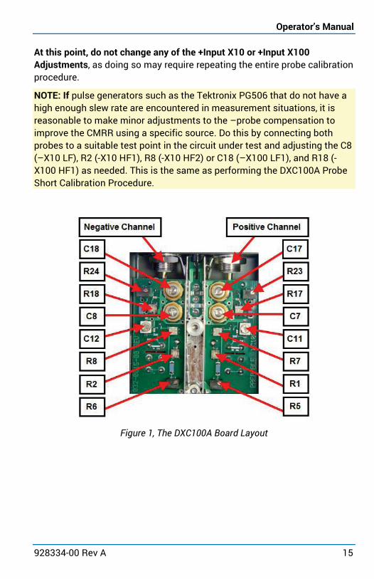
At this point, do not change any of the +Input X10 or +Input X100 Adjustments, as doing so may require repeating the entire probe calibration procedure.
NOTE: If pulse generators such as the Tektronix PG506 that do not have a high enough slew rate are encountered in measurement situations, it is reasonable to make minor adjustments to the –probe compensation to improve the CMRR using a specific source. Do this by connecting both probes to a suitable test point in the circuit under test and adjusting the C8 (–X10 LF), R2 (-X10 HF1), R8 (-X10 HF2) or C18 (–X100 LF1), and R18 (-X100 HF1) as needed. This is the same as performing the DXC100A Probe Short Calibration Procedure.
Figure 1, The DXC100A Board Layout

DXC100A Differential Probe Pair
16
Figure 2, DXC100A schematic

Operator’s Manual
928334-00 Rev A 17
Reference Certifications Teledyne LeCroy certifies compliance to the following standards as of the date of publication. For the current certifications, see the EC Declaration of Conformity shipped with your product.
EMC Compliance EC DECLARATION OF CONFORMITY - EMC The probe meets intent of EC Directive 2014/30/EU for Electromagnetic Compatibility. Compliance was demonstrated to the following specifications as listed in the Official Journal of the European Communities:
IEC/EN 61326-1:2013 EMC requirements for electrical equipment for measurement, control, and laboratory use1
Electromagnetic Emissions: IEC/EN 55011/A1:2010 Radiated and Conducted Emissions Group 1 Class A2 3
Electromagnetic Immunity: IEC/EN 61000-4-2:2009 Electrostatic Discharge, 4 kV contact, 8 kV air, 4 kV vertical/horizontal coupling planes 4
IEC/EN 61000-4-3/A2:2010 RF Radiated Electromagnetic Field, 3 V/m, 80-1000 MHz; 3 V/m, 1400 MHz - 2 GHz; 1 V/m, 2 GHz - 2.7 GHz 1 To ensure compliance with applicable EMC standards, use high-quality shielded interface cables.
2 This product is intended for use in nonresidential areas only. Use in residential areas may cause electromagnetic interference.
3 Emissions which exceed the levels required by this standard may occur when the probe is connected to a test object.
4 Meets Performance Criteria “B” limits of the respective standard: during the disturbance, product undergoes a temporary degradation or loss of function or performance which is self-recoverable.
European Contact: Teledyne LeCroy Europe GmbH Im Breitspiel 11c D-69126 Heidelberg Germany Tel: (49) 6221 82700

DXC100A Differential Probe Pair
18
AUSTRALIA & NEW ZEALAND DECLARATION OF CONFORMITY - EMC The probe complies with the EMC provision of the Radio Communications Act per the following standards, in accordance with requirements imposed by the Australian Communication and Media Authority (ACMA):
AS/NZS CISPR 11:2009/A1:2010, IEC 55011:2009/A1:2010 Radiated and Conducted Emissions, Group 1, Class A.
Australia / New Zealand Contacts:* RS Components Pty Ltd. Suite 326 The Parade West Kent Town, South Australia 5067
RS Components Ltd. Units 30 & 31 Warehouse World 761 Great South Road Penrose, Auckland, New Zealand
* Visit teledynelecroy.com/support/contact for the latest contact information.
Safety Compliance EC DECLARATION OF CONFORMITY – LOW VOLTAGE The probe meets the intent of EC Directive 2014/35/EU for Product Safety. Compliance was demonstrated to the following specifications as listed in the Official Journal of the European Communities:
IEC/EN 61010-031:2015 Safety requirements for electrical equipment for measurement, control and laboratory use – Part 031: Safety requirements for handheld probe assemblies for electrical measurement and test.
Environmental Compliance END-OF-LIFE HANDLING
The probe is marked with this symbol to indicate that it complies with the applicable European Union requirements to Directives 2012/19/EU and 2013/56/EU on Waste Electrical and Electronic Equipment (WEEE) and Batteries.
The probe is subject to disposal and recycling regulations that vary by country and region. Many countries prohibit the disposal of waste electronic equipment in standard waste receptacles. For more information about proper disposal and recycling of your Teledyne LeCroy product, visit teledynelecroy.com/recycle.
RESTRICTION OF HAZARDOUS SUBSTANCES (ROHS) The product and its accessories conform to the 2011/65/EU RoHS2 Directive.

Operator’s Manual
928334-00 Rev A 19
Specifications Refer to the product page at teledynelecroy.com/probes for detailed specifications.
Warranty Teledyne LeCroy warrants this oscilloscope accessory for normal use and operation within specification for a period of one year from the date of shipment. Spare parts, replacement parts and repairs are warranted for 90 days.
In exercising its warranty, Teledyne LeCroy, at its option, will either repair or replace any assembly returned within its warranty period to the Customer Service Department or an authorized service center. However, this will be done only if the product is determined by Teledyne LeCroy’s examination to be defective due to workmanship or materials, and the defect is not caused by misuse, neglect, accident, abnormal conditions of operation, or damage resulting from attempted repair or modifications by a non-authorized service facility.
The customer will be responsible for the transportation and insurance charges for the return of products to the service facility. Teledyne LeCroy will return all products under warranty with transportation charges prepaid.
This warranty replaces all other warranties, expressed or implied, including but not limited to any implied warranty of merchantability, fitness or adequacy for any particular purposes or use. Teledyne LeCroy shall not be liable for any special, incidental, or consequential damages, whether in contract or otherwise.

DXC100A Differential Probe Pair
20
Returning a Product for Service Contact your regional Teledyne LeCroy service center for calibration or other service. If the product cannot be serviced on location, the service center will give you a Return Material Authorization (RMA) code and instruct you where to ship the product. All products returned to the factory must have an RMA. Return shipments must be prepaid.
Teledyne LeCroy cannot accept COD or Collect shipments. We recommend air-freighting. Insure the item for at least the replacement cost.
1. Remove all accessories from the probe. Do not include the manual.
2. Pack the probe in its case, surrounded by the original packing material (or equivalent).
3. Label the case with a tag containing: • The RMA • Name and address of the owner • Probe model and serial number • Description of failure or requisite service
4. Package the probe case in a cardboard shipping box with adequate padding to avoid damage in transit.
5. Mark the outside of the box with the shipping address given to you by Teledyne LeCroy; be sure to add the following:
• ATTN: <RMA code assigned by the Teledyne LeCroy> • FRAGILE
6. Insure the item for the replacement cost of the probe.
7. If returning a probe to a different country: • Mark the shipment as a “Return of US manufactured goods
for warranty repair/recalibration.” • If there is a cost for the service, list the cost in the value
column and the original purchase price “For insurance purposes only.”
• Be very specific as to the reason for shipment. Duties may have to be paid on the value of the service.

Operator’s Manual
928334-00 Rev A 21
Technical Support Live Support Registered users can contact their local Teledyne LeCroy service center at the number listed on our website. You can also request Technical Support via the website at:
teledynelecroy.com/support/techhelp
Resources Teledyne LeCroy publishes a free Technical Library on its website. Manuals, tutorials, application notes, white papers, and videos are available to help you get the most out of your Teledyne LeCroy products. Visit:
teledynelecroy.com/support/techlib
Service Centers For a complete list of offices by country, including our sales and distribution partners, visit:
teledynelecroy.com/support/contact
Teledyne LeCroy 700 Chestnut Ridge Road Chestnut Ridge, NY, 10977, USA
Sales and Service: Ph: 800-553-2769 / 845-425-2000 FAX: 845-578-5985 [email protected]
Support: Ph: 800-553-2769 [email protected]
928334-00 Rev A April, 2017