Embed Size (px)
Citation preview
DXR heat RecoveRy ventilation - Design anD installation guiDe

Update 11.04.2014 I DXR design and installation guide i aereco i 3
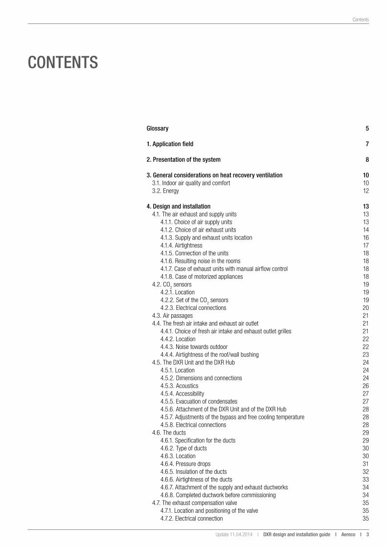
Contents
Contents
glossary 5
1. application field 7
2. Presentation of the system 8
3. general considerations on heat recovery ventilation 103.1. Indoor air quality and comfort 103.2. Energy 12
4. Design and installation 134.1. The air exhaust and supply units 13
4.1.1. Choice of air supply units 134.1.2. Choice of air exhaust units 144.1.3. Supply and exhaust units location 164.1.4. Airtightness 174.1.5. Connection of the units 184.1.6. Resulting noise in the rooms 184.1.7. Case of exhaust units with manual airflow control 184.1.8. Case of motorized appliances 18
4.2. CO2 sensors 194.2.1. Location 194.2.2. Set of the CO2 sensors 194.2.3. Electrical connections 20
4.3. Air passages 214.4. The fresh air intake and exhaust air outlet 21
4.4.1. Choice of fresh air intake and exhaust outlet grilles 214.4.2. Location 224.4.3. Noise towards outdoor 224.4.4. Airtightness of the roof/wall bushing 23
4.5. The DXR Unit and the DXR Hub 244.5.1. Location 244.5.2. Dimensions and connections 244.5.3. Acoustics 264.5.4. Accessibility 274.5.5. Evacuation of condensates 274.5.6. Attachment of the DXR Unit and of the DXR Hub 284.5.7. Adjustments of the bypass and free cooling temperature 284.5.8. Electrical connections 28
4.6. The ducts 294.6.1. Specification for the ducts 294.6.2. Type of ducts 304.6.3. Location 304.6.4. Pressure drops 314.6.5. Insulation of the ducts 324.6.6. Airtightness of the ducts 334.6.7. Attachment of the supply and exhaust ductworks 344.6.8. Completed ductwork before commissioning 34
4.7. The exhaust compensation valve 354.7.1. Location and positioning of the valve 354.7.2. Electrical connection 35
4 i aereco i DXR design and installation guide I Update 11.04.2014 I
Contents
4.8. Defrosting 364.8.1. Anti-frost operating 364.8.2. Location and positioning of the defrosting 364.8.3. Electrical connection 36
4.9. The DXR user interface 374.9.1. Key features 374.9.2. Location 374.9.3. Electrical connection 37
5. Certifications 38
6. Fire protection 39
7. anticipate maintenance in the design 40
8. Creation of a technical file 41
9. acceptance of works 429.1. Visual inspection 429.2. Measurements 43
10. servicing and maintenance 44
appendices 45Technical characteristics of the DXR 45Electrical connections 48
Update 11.04.2014 I DXR design and installation guide i aereco i 5
Glossary
glossaRy
air passage: clearance under doors, allowing the movement of the air through the dwelling.
air supplied (supply): preheated fresh air, supplied in the main rooms (bedrooms, living rooms, etc.).
Bypass: parallel circuit, avoiding the fresh air inlet to pass though the exchanger.
Counter-flow exchanger: parallel and opposite direction flow circulation in the exchanger.
exhaust air: used and heated air (during heating season), entering the DXR Unit in order to transfer part of the heat to the fresh air.
exhaust air outlet (used air / discharge): exhaust for the used air with inside pollutant, to be exhausted outside.
Free-cooling: increase of the airflow rate in hot periods when, because of heat transfer and outdoors temperature, the inside temperature is higher than the outside one.
Fresh air inlet (air intake): part of the system providing healthy air from outside, entering the DXR Unit.
Heated space: insulated area of the dwelling, with a temperature above 18°C.
Heat recovery ventilation: ventilation system with two airflows ductwork (supply and exhaust air), including a heat exchanger.
Humidity controlled unit: unit located in the wet rooms (kitchen, bathroom, etc.) which automatically adjust the airflow depending on the room humidity, without electricity (mechanical).
night-cooling: increase of the airflow during the night, in hot period, to cool the dwelling.
supply unit: unit located in the main rooms to bring fresh air into the dwelling (bedrooms, living rooms, etc.).

Update 11.04.2014 I DXR design and installation guide i aereco i 7
Application field
1. aPPliCation FielD
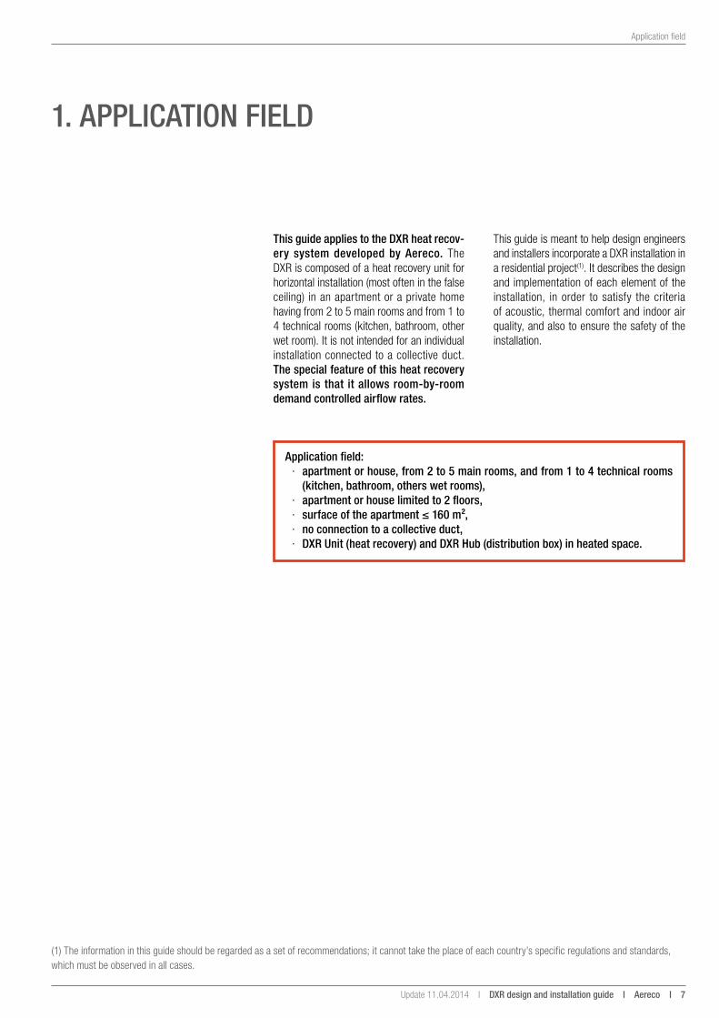
this guide applies to the DXR heat recov-ery system developed by aereco. The DXR is composed of a heat recovery unit for horizontal installation (most often in the false ceiling) in an apartment or a private home having from 2 to 5 main rooms and from 1 to 4 technical rooms (kitchen, bathroom, other wet room). It is not intended for an individual installation connected to a collective duct. the special feature of this heat recovery system is that it allows room-by-room demand controlled airflow rates.
(1) The information in this guide should be regarded as a set of recommendations; it cannot take the place of each country’s specific regulations and standards, which must be observed in all cases.
This guide is meant to help design engineers and installers incorporate a DXR installation in a residential project(1). It describes the design and implementation of each element of the installation, in order to satisfy the criteria of acoustic, thermal comfort and indoor air quality, and also to ensure the safety of the installation.
application field: · apartment or house, from 2 to 5 main rooms, and from 1 to 4 technical rooms
(kitchen, bathroom, others wet rooms), · apartment or house limited to 2 floors, · surface of the apartment ≤ 160 m², · no connection to a collective duct, · DXR unit (heat recovery) and DXR Hub (distribution box) in heated space.
8 i aereco i DXR design and installation guide I Update 11.04.2014 I
Presentation of the system
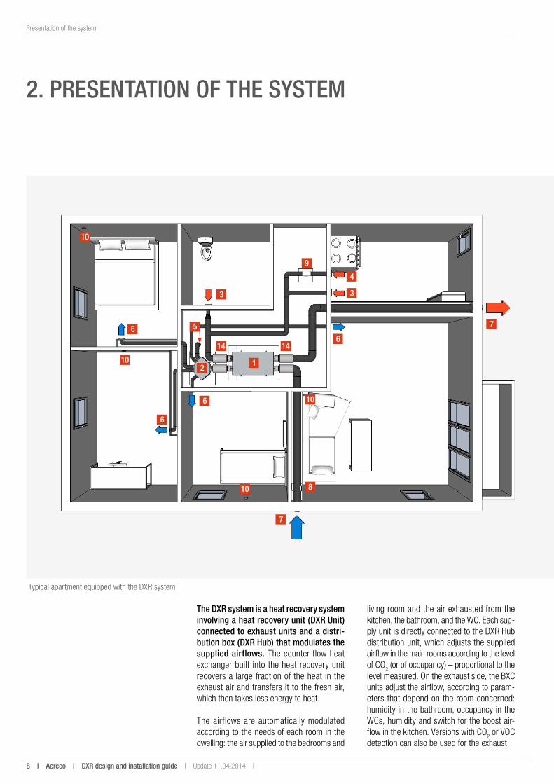
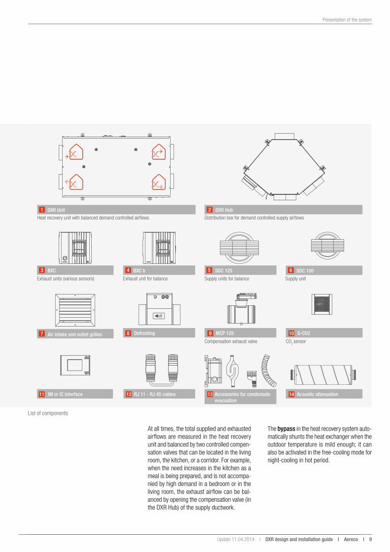
the DXR system is a heat recovery system involving a heat recovery unit (DXR unit) connected to exhaust units and a distri-bution box (DXR Hub) that modulates the supplied airflows. The counter-flow heat exchanger built into the heat recovery unit recovers a large fraction of the heat in the exhaust air and transfers it to the fresh air, which then takes less energy to heat.
The airflows are automatically modulated according to the needs of each room in the dwelling: the air supplied to the bedrooms and
2. PResentation oF tHe system
Typical apartment equipped with the DXR system
1
5
33
6
6
6
6
4
7
7
10
10
10
8
9
1414
102
living room and the air exhausted from the kitchen, the bathroom, and the WC. Each sup-ply unit is directly connected to the DXR Hub distribution unit, which adjusts the supplied airflow in the main rooms according to the level of CO2 (or of occupancy) – proportional to the level measured. On the exhaust side, the BXC units adjust the airflow, according to param-eters that depend on the room concerned: humidity in the bathroom, occupancy in the WCs, humidity and switch for the boost air-flow in the kitchen. Versions with CO2 or VOC detection can also be used for the exhaust.
Update 11.04.2014 I DXR design and installation guide i aereco i 9
Presentation of the system
At all times, the total supplied and exhausted airflows are measured in the heat reco very unit and balanced by two controlled compen-sation valves that can be located in the living room, the kitchen, or a corridor. For example, when the need increases in the kitchen as a meal is being prepared, and is not accompa-nied by high demand in a bedroom or in the living room, the exhaust airflow can be bal-anced by opening the compensation valve (in the DXR Hub) of the supply ductwork.
DXR Unit1 DXR Hub2
Distribution box for demand controlled supply airflows
Air intake and outlet grilles7
BXC3 BXC b4 SDC 1255 SDC 1006
IM or IC interface11 Acoustic attenuation14
Heat recovery unit with balanced demand controlled airflows
Exhaust units (various sensors) Exhaust unit for balance Supply units for balance
S-CO210
CO2 sensor
Defrosting8 MCP 1259
Compensation exhaust valve
Supply unit
RJ 11 - RJ 45 cables12 Accessories for condensate evacuation
13
List of components
The bypass in the heat recovery system auto-matically shunts the heat exchanger when the outdoor temperature is mild enough; it can also be activated in the free-cooling mode for night-cooling in hot period.
10 i aereco i DXR design and installation guide I Update 11.04.2014 I
General considerations on heat recovery ventilation I Indoor air quality and comfort
3. geneRal ConsiDeRations on Heat ReCoveRy ventilation
Heat recovery ventilation systems in general and the DXR in particular have many benefits in terms of indoor air quality, comfort, and energy savings, as long as they are correctly installed, in a heated volume, and regularly maintained. Attention must be paid to these points from the start of a project.
3.1. indoor air quality and comfort
1
4
2
5
3
6
7
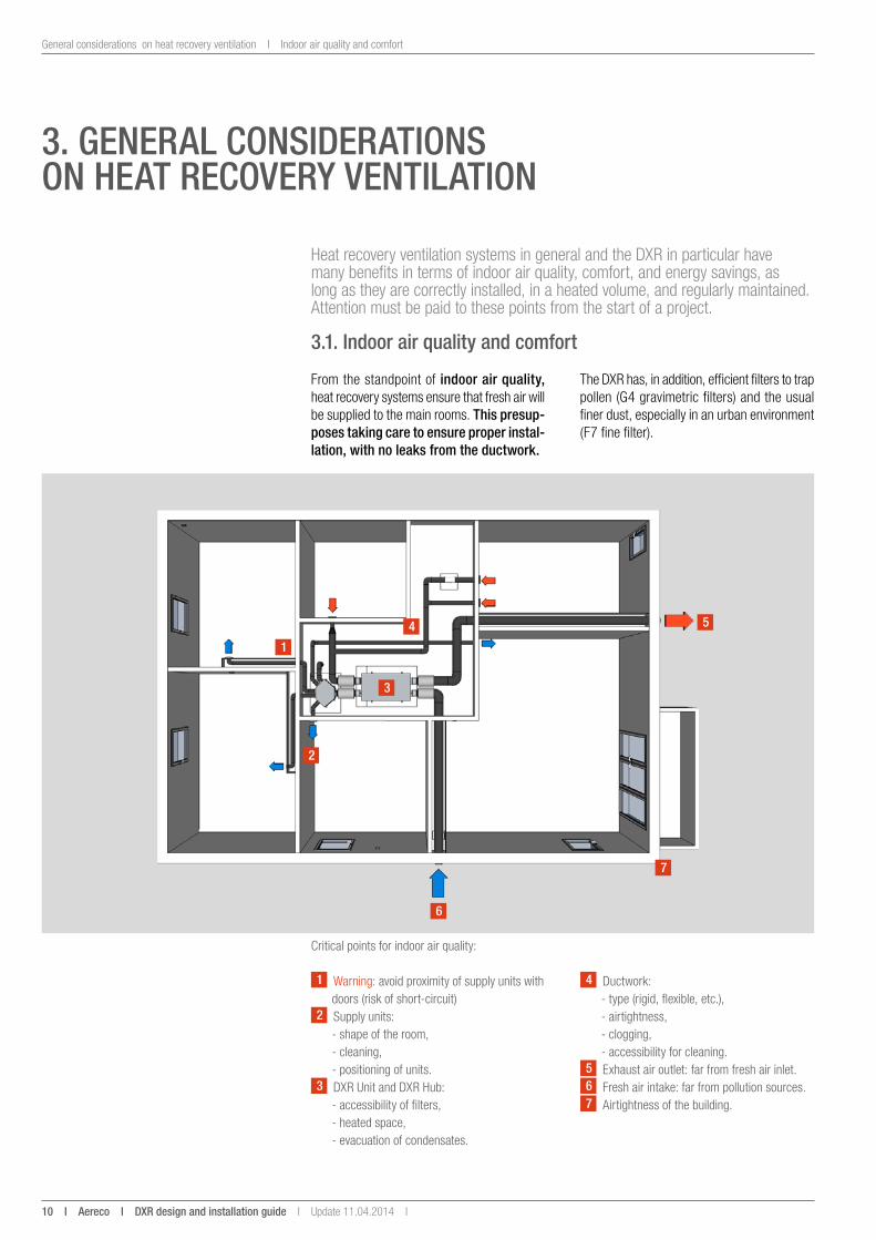
Critical points for indoor air quality:
From the standpoint of indoor air quality, heat recovery systems ensure that fresh air will be supplied to the main rooms. this presup-poses taking care to ensure proper instal-lation, with no leaks from the ductwork.
4 Ductwork: - type (rigid, flexible, etc.), - airtightness, - clogging, - accessibility for cleaning.
5 Exhaust air outlet: far from fresh air inlet.6 Fresh air intake: far from pollution sources.7 Airtightness of the building.
The DXR has, in addition, efficient filters to trap pollen (G4 gravimetric filters) and the usual finer dust, especially in an urban environment (F7 fine filter).
1 Warning: avoid proximity of supply units with doors (risk of short-circuit)
2 Supply units: - shape of the room, - cleaning, - positioning of units.
3 DXR Unit and DXR Hub: - accessibility of filters, - heated space, - evacuation of condensates.
Update 11.04.2014 I DXR design and installation guide i aereco i 11
Indoor air quality and comfort I General considerations on heat recovery ventilation
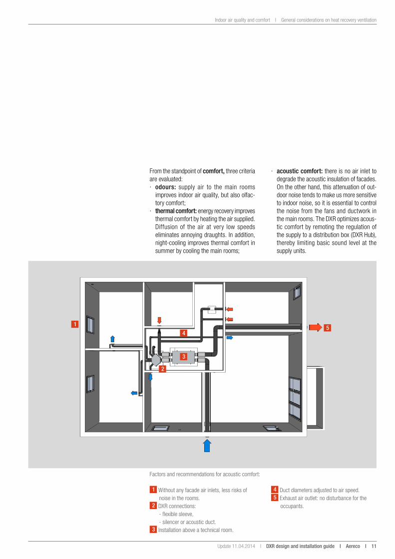
From the standpoint of comfort, three criteria are evaluated: · odours: supply air to the main rooms
improves indoor air quality, but also olfac-tory comfort;
· thermal comfort: energy recovery improves thermal comfort by heating the air supplied. Diffusion of the air at very low speeds eliminates annoying draughts. In addition, night-cooling improves thermal comfort in summer by cooling the main rooms;
14
2
5
3
Factors and recommendations for acoustic comfort:
4 Duct diameters adjusted to air speed.5 Exhaust air outlet: no disturbance for the
occupants.
· acoustic comfort: there is no air inlet to degrade the acoustic insulation of facades. On the other hand, this attenuation of out-door noise tends to make us more sensitive to indoor noise, so it is essential to control the noise from the fans and ductwork in the main rooms. The DXR optimizes acous-tic comfort by remoting the regulation of the supply to a distribution box (DXR Hub), thereby limiting basic sound level at the supply units.
1 Without any facade air inlets, less risks of noise in the rooms.
2 DXR connections: - flexible sleeve, - silencer or acoustic duct.
3 Installation above a technical room.
12 i aereco i DXR design and installation guide I Update 11.04.2014 I
General considerations on heat recovery ventilation I Energy
3.2. energy
WaRningthe systems must be installed by experienced contractors, trained in the specificities of the process and having the necessary skills in venti-lation and electricity.
energy is a main concern. In standard heat recovery systems, the energy saving depends on energy recovery by the exchanger. By add-ing room-by-room modulation of flows to heat recovery, the DXR optimizes energy perfor-mance (the system reduces the heating and electricity consumption).
For the system as a whole to be effective, we strongly recommend locating the DXR in the heated volume, along with the duct (otherwise, they must be thermally insulated), and controlling leaks from the ductwork. the thermal performance of heat recovery systems also depends on how airtight the building in which they are installed is.
Update 11.04.2014 I DXR design and installation guide i aereco i 13
The air exhaust and supply units I Design and installation
This part spells out, component by component, what must be done with each element in order to obtain a system that performs well in terms of both aeraulics, thermal and acoustic comfort.
4.1. the air exhaust and supply units
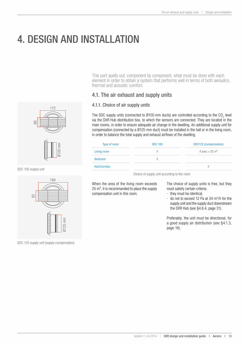
SDC 100 supply unit
SDC 125 supply unit (supply compensation)
Choice of supply unit according to the room
Ø100
mm
172
6882
Ø125
mm
194
4.1.1. Choice of air supply units
The SDC supply units (connected to Ø100 mm ducts) are controlled according to the CO2 level via the DXR Hub distribution box, to which the sensors are connected. They are located in the main rooms, in order to ensure adequate air change in the dwelling. An additional supply unit for compensation (connected by a Ø125 mm duct) must be installed in the hall or in the living room, in order to balance the total supply and exhaust airflows of the dwelling.
type of room sDC 100 sDC125 (compensation)
living room X if area > 25 m²
Bedroom X
Hall/Corridor X
4. Design anD installation
When the area of the living room exceeds 25 m², it is recommanded to place the supply compensation unit in this room.
The choice of supply units is free, but they must satisfy certain criteria: · they must be identical, · do not to exceed 12 Pa at 34 m3/h for the
supply unit and the supply duct downstream the DXR Hub (see §4.6.4, page 31).
Preferably, the unit must be directional, for a good supply air distribution (see §4.1.3, page 16).
14 i aereco i DXR design and installation guide I Update 11.04.2014 I
Design and installation I The air exhaust and supply units
BXC h BXC p BXC hi BXC hp BXC pdBXC hpd
BXC Co2
BXC voc
BXC rc BFX BXC b
Control settings
Hum
idity
Pres
ence
Hum
idity
+ s
witc
h
Hum
idity
+
pres
ence
Pres
ence
with
del
ay
Hum
idid
ty +
pr
esen
ce w
ith d
elay
Carb
on d
ioxy
de
(Co 2)
vola
til o
rgan
ic
com
poun
ds (v
oC)
Rem
ote
Cont
rol
Fix
exha
ust
com
pens
atio
n
Hous
ing
Kitchen ++ ++++ ++ +++ + +++
Bathroom ++++ +++ +++ +++ +
WC ++++ ++ +++ ++++ +++ ++ +++ +
Bathroom with WC + + ++ +++ ++++ ++
laundry ++++ +++ + ++
Hall +(2)
169
174
Ø100
mm
169
174
Ø125
mm
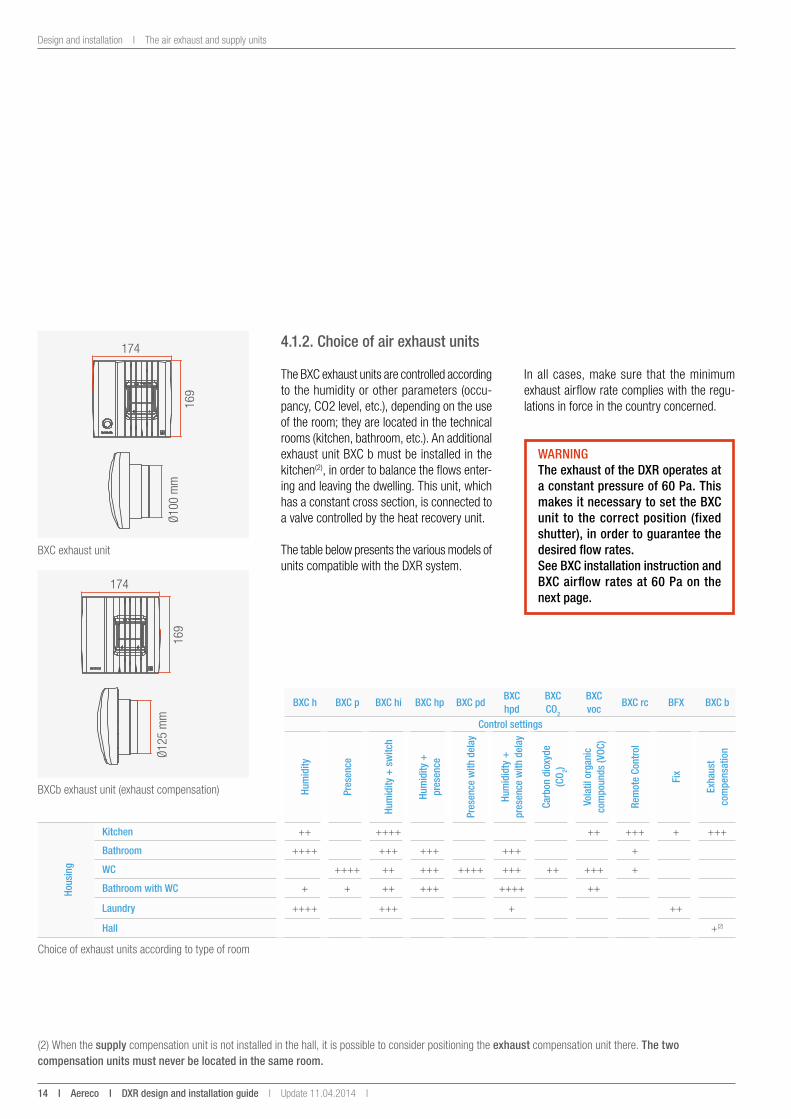
BXC exhaust unit
BXCb exhaust unit (exhaust compensation)
(2) When the supply compensation unit is not installed in the hall, it is possible to consider positioning the exhaust compensation unit there. the two compensation units must never be located in the same room.
Choice of exhaust units according to type of room
4.1.2. Choice of air exhaust units
WaRningthe exhaust of the DXR operates at a constant pressure of 60 Pa. this makes it necessary to set the BXC unit to the correct position (fixed shutter), in order to guarantee the desired flow rates.see BXC installation instruction and BXC airflow rates at 60 Pa on the next page.
The BXC exhaust units are controlled according to the humidity or other parameters (occu-pancy, CO2 level, etc.), depending on the use of the room; they are located in the technical rooms (kitchen, bathroom, etc.). An additional exhaust unit BXC b must be installed in the kitchen(2), in order to balance the flows enter-ing and leaving the dwelling. This unit, which has a constant cross section, is connected to a valve controlled by the heat recovery unit.
The table below presents the various models of units compatible with the DXR system.
In all cases, make sure that the minimum exhaust airflow rate complies with the regu-lations in force in the country concerned.
Update 11.04.2014 I DXR design and installation guide i aereco i 15
The air exhaust and supply units I Design and installation
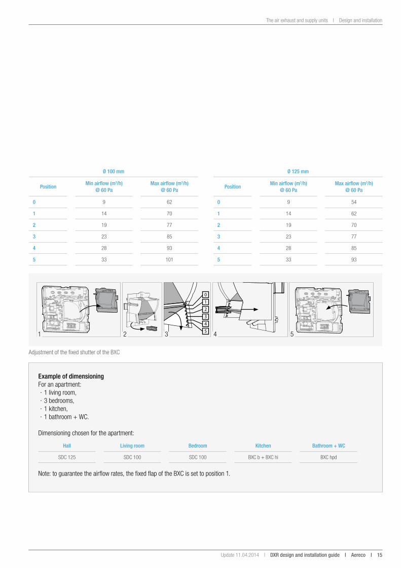
Adjustment of the fixed shutter of the BXC
example of dimensioning For an apartment:
· 1 living room, · 3 bedrooms, · 1 kitchen, · 1 bathroom + WC.
Dimensioning chosen for the apartment:
Hall living room Bedroom Kitchen Bathroom + WC
SDC 125 SDC 100 SDC 100 BXC b + BXC hi BXC hpd
Note: to guarantee the airflow rates, the fixed flap of the BXC is set to position 1.
41 52
0
1
2
3
4
53
Ø 125 mm
Positionmin airflow (m3/h)
@ 60 Pamax airflow (m3/h)
@ 60 Pa
0 9 54
1 14 62
2 19 70
3 23 77
4 28 85
5 33 93
Ø 100 mm
Positionmin airflow (m3/h)
@ 60 Pamax airflow (m3/h)
@ 60 Pa
0 9 62
1 14 70
2 19 77
3 23 85
4 28 93
5 33 101
16 i aereco i DXR design and installation guide I Update 11.04.2014 I
Design and installation I The air exhaust and supply units
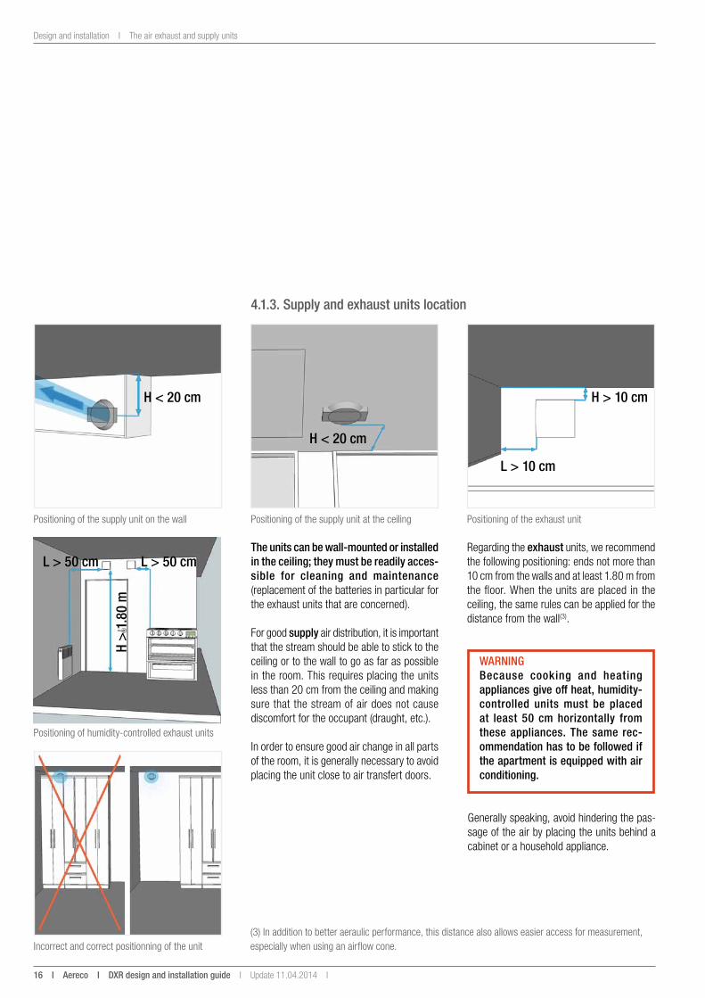
4.1.3. supply and exhaust units location
(3) In addition to better aeraulic performance, this distance also allows easier access for measurement, especially when using an airflow cone.
Positioning of the supply unit on the wall Positioning of the exhaust unitPositioning of the supply unit at the ceiling
Positioning of humidity-controlled exhaust units
Incorrect and correct positionning of the unit
the units can be wall-mounted or installed in the ceiling; they must be readily acces-sible for cleaning and maintenance (replacement of the batteries in particular for the exhaust units that are concerned).
For good supply air distribution, it is important that the stream should be able to stick to the ceiling or to the wall to go as far as possible in the room. This requires placing the units less than 20 cm from the ceiling and making sure that the stream of air does not cause discomfort for the occupant (draught, etc.).
In order to ensure good air change in all parts of the room, it is generally necessary to avoid placing the unit close to air transfert doors.
H < 20 cm
H < 20 cm
H > 10 cm
l > 10 cm
l > 50 cm
H >
1.80
m
l > 50 cm
WaRningBecause cooking and heating appliances give off heat, humidity- controlled units must be placed at least 50 cm horizontally from these appliances. the same rec-ommendation has to be followed if the apartment is equipped with air conditioning.
Regarding the exhaust units, we recommend the following positioning: ends not more than 10 cm from the walls and at least 1.80 m from the floor. When the units are placed in the ceiling, the same rules can be applied for the distance from the wall(3).
Generally speaking, avoid hindering the pas-sage of the air by placing the units behind a cabinet or a household appliance.
Update 11.04.2014 I DXR design and installation guide i aereco i 17
The air exhaust and supply units I Design and installation
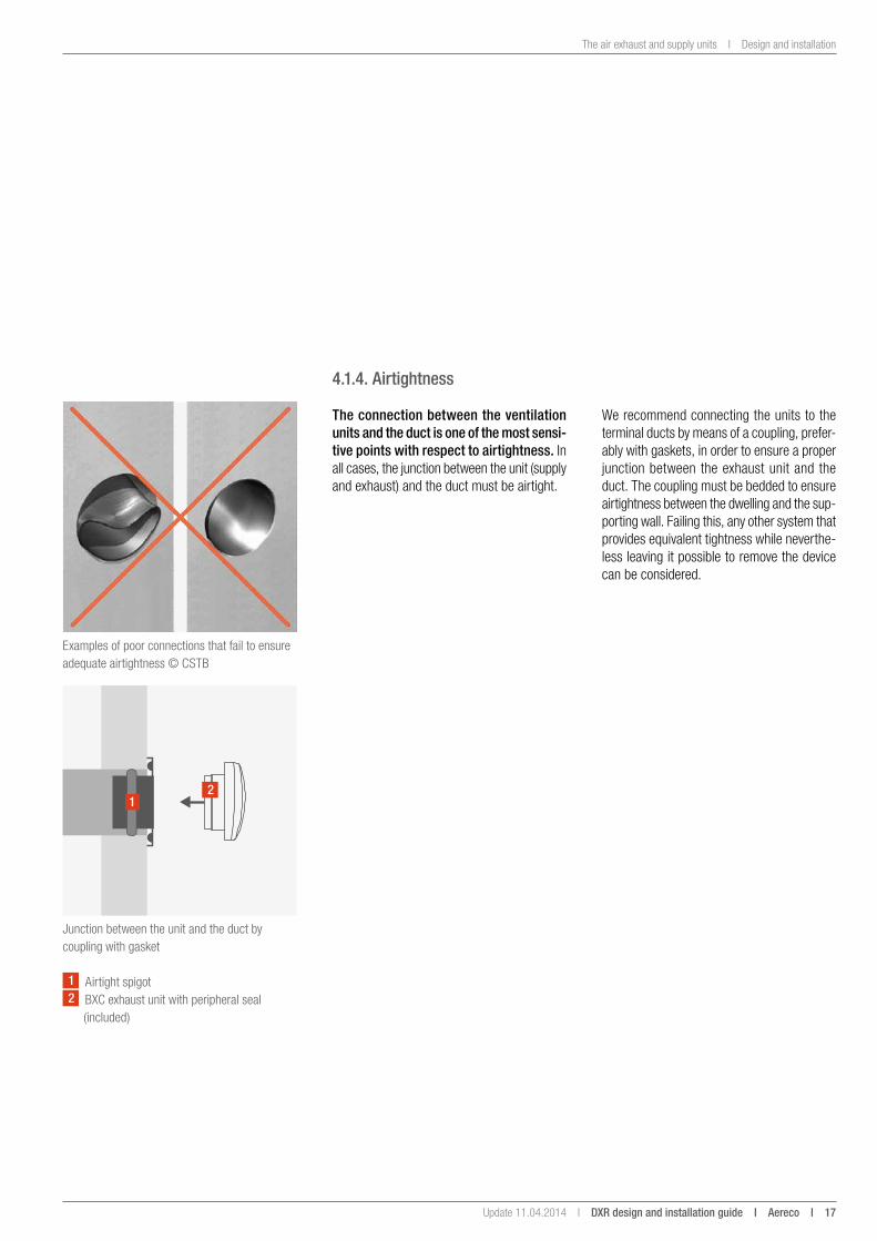
4.1.4. airtightness
the connection between the ventilation units and the duct is one of the most sensi-tive points with respect to airtightness. In all cases, the junction between the unit (supply and exhaust) and the duct must be airtight.
Examples of poor connections that fail to ensure adequate airtightness © CSTB
Junction between the unit and the duct by coupling with gasket
1 Airtight spigot2 BXC exhaust unit with peripheral seal
(included)
12
We recommend connecting the units to the terminal ducts by means of a coupling, prefer-ably with gaskets, in order to ensure a proper junction between the exhaust unit and the duct. The coupling must be bedded to ensure airtightness between the dwelling and the sup-porting wall. Failing this, any other system that provides equivalent tightness while neverthe-less leaving it possible to remove the device can be considered.
18 i aereco i DXR design and installation guide I Update 11.04.2014 I
Design and installation I The air exhaust and supply units
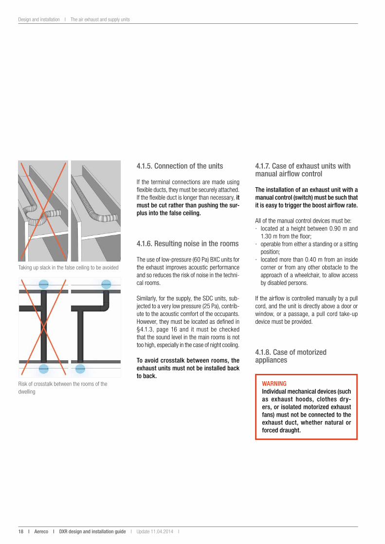
Taking up slack in the false ceiling to be avoided
Risk of crosstalk between the rooms of the dwelling
WaRningindividual mechanical devices (such as exhaust hoods, clothes dry-ers, or isolated motorized exhaust fans) must not be connected to the exhaust duct, whether natural or forced draught.
4.1.5. Connection of the units
If the terminal connections are made using flexible ducts, they must be securely attached. If the flexible duct is longer than necessary, it must be cut rather than pushing the sur-plus into the false ceiling.
4.1.6. Resulting noise in the rooms
The use of low-pressure (60 Pa) BXC units for the exhaust improves acoustic performance and so reduces the risk of noise in the techni-cal rooms.
Similarly, for the supply, the SDC units, sub-jected to a very low pressure (25 Pa), contrib-ute to the acoustic comfort of the occupants. However, they must be located as defined in §4.1.3, page 16 and it must be checked that the sound level in the main rooms is not too high, especially in the case of night cooling.
to avoid crosstalk between rooms, the exhaust units must not be installed back to back.
4.1.7. Case of exhaust units with manual airflow control
the installation of an exhaust unit with a manual control (switch) must be such that it is easy to trigger the boost airflow rate.
All of the manual control devices must be: · located at a height between 0.90 m and
1.30 m from the floor; · operable from either a standing or a sitting
position; · located more than 0.40 m from an inside
corner or from any other obstacle to the approach of a wheelchair, to allow access by disabled persons.
If the airflow is controlled manually by a pull cord, and the unit is directly above a door or window, or a passage, a pull cord take-up device must be provided.
4.1.8. Case of motorized appliances
Update 11.04.2014 I DXR design and installation guide i aereco i 19
CO2 sensors I Design and installation
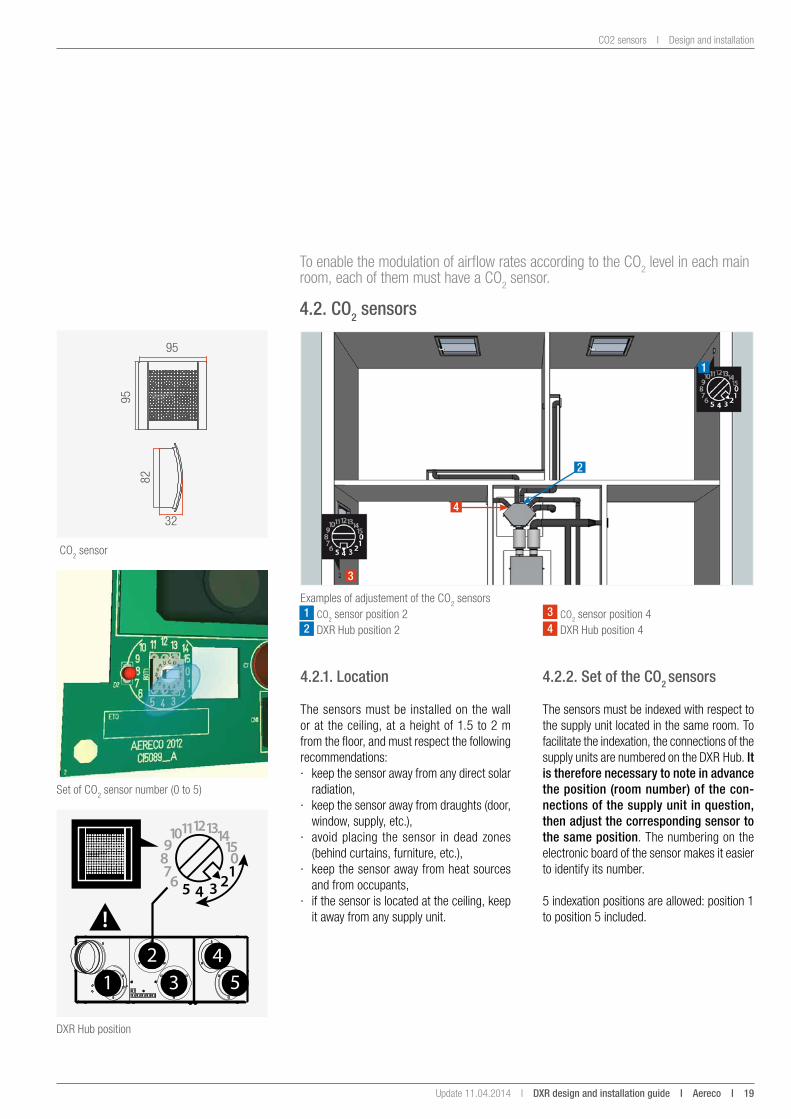
95
95
82
32
CO2 sensor
To enable the modulation of airflow rates according to the CO2 level in each main room, each of them must have a CO2 sensor.
4.2. Co2 sensors
Examples of adjustement of the CO2 sensors
Set of CO2 sensor number (0 to 5)
1 CO2 sensor position 22 DXR Hub position 2
1
3
2
4
4.2.1. location
The sensors must be installed on the wall or at the ceiling, at a height of 1.5 to 2 m from the floor, and must respect the following recommendations: · keep the sensor away from any direct solar
radiation, · keep the sensor away from draughts (door,
window, supply, etc.), · avoid placing the sensor in dead zones
(behind curtains, furniture, etc.), · keep the sensor away from heat sources
and from occupants, · if the sensor is located at the ceiling, keep
it away from any supply unit.
4.2.2. set of the Co2 sensors
The sensors must be indexed with respect to the supply unit located in the same room. To facilitate the indexation, the connections of the supply units are numbered on the DXR Hub. it is therefore necessary to note in advance the position (room number) of the con-nections of the supply unit in question, then adjust the corresponding sensor to the same position. The numbering on the electronic board of the sensor makes it easier to identify its number.
5 indexation positions are allowed: position 1 to position 5 included.
1 34
52
TF54
14_A
DXR Hub position
3 CO2 sensor position 44 DXR Hub position 4
20 i aereco i DXR design and installation guide I Update 11.04.2014 I
Design and installation I CO2 sensors
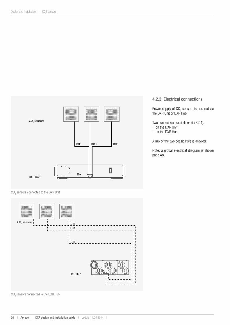
CO2 sensors connected to the DXR Unit
CO2 sensors connected to the DXR Hub
4.2.3. electrical connections
Power supply of CO2 sensors is ensured via the DXR Unit or DXR Hub.
Two connection possibilities (in RJ11): · on the DXR Unit, · on the DXR Hub.
A mix of the two possibilities is allowed.
Note: a global electrical diagram is shown page 48.
RJ11 RJ11 RJ11
DXR Unit
CO2 sensors
RJ11
RJ11
RJ11
DXR Hub
CO2 sensors
Update 11.04.2014 I DXR design and installation guide i aereco i 21
Air passages I Design and installation
4.3. air passages
To enable the air circulation from the main rooms to the technical rooms, clearances under doors must be realised:
Kitchen door(s) other interior doors
Height of clearance1 door: 2 cm2 doors: 1 cm
All doors: 1 cm
Transfer grilles can be used on the door that leads to the kitchen. In this case, they must have a cross-sectional area of at least 100 cm².
When choosing the interior doors of the dwell-ing, this recommendation must be verified.
WaRningadding carpeting or other floor sur-facing after installing the doors may reduce the clearance and consider-ably reduce the air passage.
4.4. the fresh air intake and exhaust air outlet
4.4.1. Choice of fresh air intake and exhaust outlet grilles
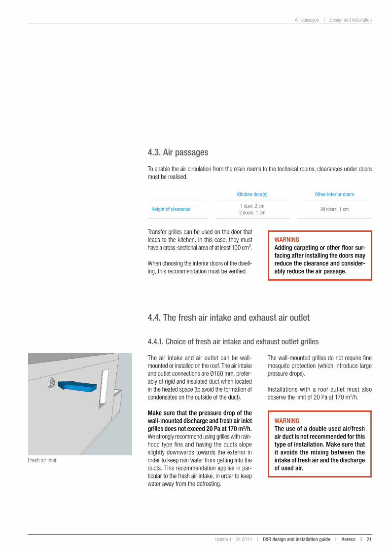
The air intake and air outlet can be wall-mounted or installed on the roof. The air intake and outlet connections are Ø160 mm, prefer-ably of rigid and insulated duct when located in the heated space (to avoid the formation of condensates on the outside of the duct).
make sure that the pressure drop of the wall-mounted discharge and fresh air inlet grilles does not exceed 20 Pa at 170 m3/h. We strongly recommend using grilles with rain-hood type fins and having the ducts slope slightly downwards towards the exterior in order to keep rain water from getting into the ducts. This recommendation applies in par-ticular to the fresh air intake, in order to keep water away from the defrosting.
The wall-mounted grilles do not require fine mosquito protection (which introduce large pressure drops).
Installations with a roof outlet must also observe the limit of 20 Pa at 170 m3/h.
WaRningthe use of a double used air/fresh air duct is not recommended for this type of installation. make sure that it avoids the mixing between the intake of fresh air and the discharge of used air.
Fresh air inlet
22 i aereco i DXR design and installation guide I Update 11.04.2014 I
Design and installation I The fresh air intake and exhaust air outlet
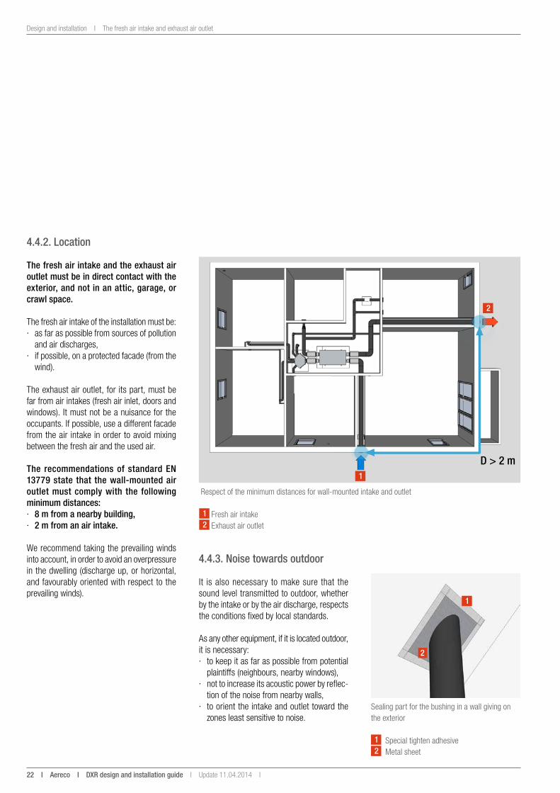
Respect of the minimum distances for wall-mounted intake and outlet
4.4.2. location
the fresh air intake and the exhaust air outlet must be in direct contact with the exterior, and not in an attic, garage, or crawl space.
The fresh air intake of the installation must be: · as far as possible from sources of pollution
and air discharges, · if possible, on a protected facade (from the
wind).
The exhaust air outlet, for its part, must be far from air intakes (fresh air inlet, doors and windows). It must not be a nuisance for the occupants. If possible, use a different facade from the air intake in order to avoid mixing between the fresh air and the used air.
the recommendations of standard en 13779 state that the wall-mounted air outlet must comply with the following minimum distances: · 8 m from a nearby building, · 2 m from an air intake.
We recommend taking the prevailing winds into account, in order to avoid an overpressure in the dwelling (discharge up, or horizontal, and favourably oriented with respect to the prevailing winds).
1 Fresh air intake2 Exhaust air outlet
1
2
D > 2 m
4.4.3. noise towards outdoor
It is also necessary to make sure that the sound level transmitted to outdoor, whether by the intake or by the air discharge, respects the conditions fixed by local standards.
As any other equipment, if it is located outdoor, it is necessary: · to keep it as far as possible from potential
plaintiffs (neighbours, nearby windows), · not to increase its acoustic power by reflec-
tion of the noise from nearby walls, · to orient the intake and outlet toward the
zones least sensitive to noise.Sealing part for the bushing in a wall giving on the exterior
1
2
1 Special tighten adhesive2 Metal sheet
Update 11.04.2014 I DXR design and installation guide i aereco i 23
The fresh air intake and exhaust air outlet I Design and installation
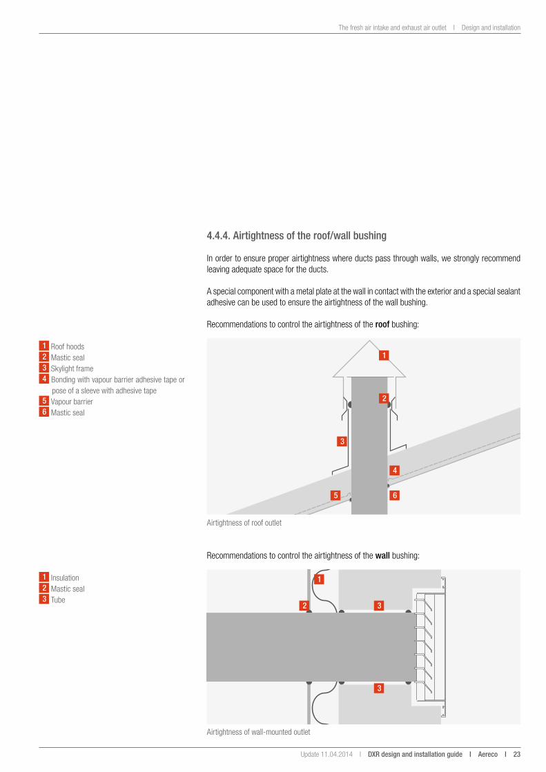
4.4.4. airtightness of the roof/wall bushing
In order to ensure proper airtightness where ducts pass through walls, we strongly recommend leaving adequate space for the ducts.
A special component with a metal plate at the wall in contact with the exterior and a special sealant adhesive can be used to ensure the airtightness of the wall bushing.
Recommendations to control the airtightness of the roof bushing:
Airtightness of roof outlet
Airtightness of wall-mounted outlet
Recommendations to control the airtightness of the wall bushing:
1
2
3
3
1
2
5 6
4
3
1 Roof hoods2 Mastic seal3 Skylight frame4 Bonding with vapour barrier adhesive tape or
pose of a sleeve with adhesive tape5 Vapour barrier6 Mastic seal
1 Insulation2 Mastic seal3 Tube
24 i aereco i DXR design and installation guide I Update 11.04.2014 I
Design and installation I The DXR Unit and the DXR Hub
The DXR Unit and the DXR Hub can be installed in a corridor or any other room in the heated space, ideally in parts of the dwelling relatively insensitive to noise.
4.5. the DXR unit and the DXR Hub
4.5.1. location
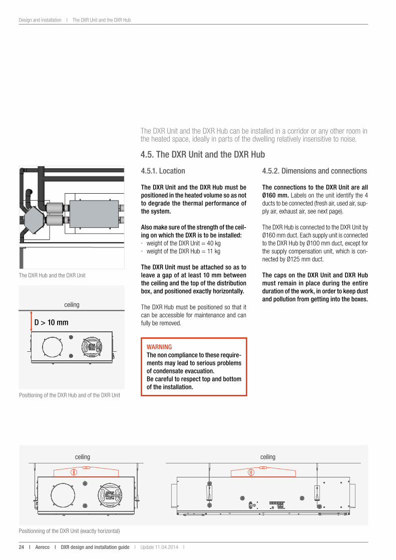
the DXR unit and the DXR Hub must be positioned in the heated volume so as not to degrade the thermal performance of the system.
also make sure of the strength of the ceil-ing on which the DXR is to be installed: · weight of the DXR Unit = 40 kg · weight of the DXR Hub = 11 kg
the DXR unit must be attached so as to leave a gap of at least 10 mm between the ceiling and the top of the distribution box, and positioned exactly horizontally.
The DXR Hub must be positioned so that it can be accessible for maintenance and can fully be removed.
The DXR Hub and the DXR Unit
Positioning of the DXR Hub and of the DXR Unit
Positionning of the DXR Unit (exactly horizontal)
D > 10 mm
ceiling
ceiling ceiling
WaRningthe non compliance to these require-ments may lead to serious problems of condensate evacuation.Be careful to respect top and bottom of the installation.
4.5.2. Dimensions and connections
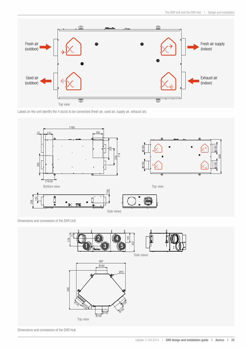
the connections to the DXR unit are all Ø160 mm. Labels on the unit identify the 4 ducts to be connected (fresh air, used air, sup-ply air, exhaust air, see next page).
The DXR Hub is connected to the DXR Unit by Ø160 mm duct. Each supply unit is connected to the DXR Hub by Ø100 mm duct, except for the supply compensation unit, which is con-nected by Ø125 mm duct.
the caps on the DXR unit and DXR Hub must remain in place during the entire duration of the work, in order to keep dust and pollution from getting into the boxes.
Update 11.04.2014 I DXR design and installation guide i aereco i 25
The DXR Unit and the DXR Hub I Design and installation
Labels on the unit identify the 4 ducts to be connected (fresh air, used air, supply air, exhaust air).
Fresh air(outdoor)
Used air(outdoor)
Fresh air supply(indoor)
Exhaust air(indoor)
Top view
258 1
24
158
1160
37
714
218,50
160137
335
316
335
16
0
160
160
160
648
128 7
3 1
78
257
545
Ø100 Ø100 Ø125
Ø15
687
Ø160
Ø100 Ø100
Ø100
1 34
52
Dimensions and connexions of the DXR Unit
Dimensions and connexions of the DXR Hub
Bottom view
Side views
Side views
Top view
Top view
26 i aereco i DXR design and installation guide I Update 11.04.2014 I
Design and installation I The DXR Unit and the DXR Hub
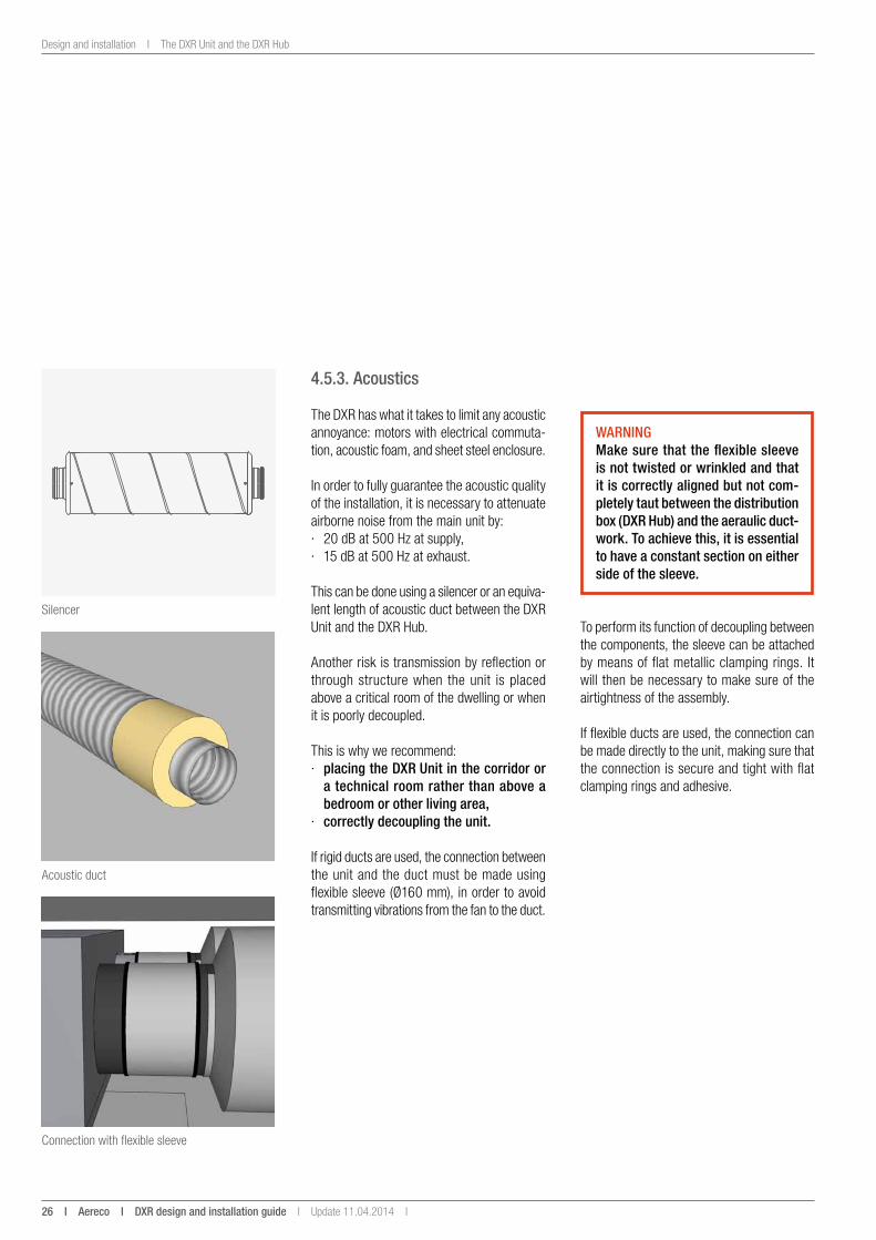
4.5.3. acoustics
The DXR has what it takes to limit any acoustic annoyance: motors with electrical commuta-tion, acoustic foam, and sheet steel enclosure.
In order to fully guarantee the acoustic quality of the installation, it is necessary to attenuate airborne noise from the main unit by: · 20 dB at 500 Hz at supply, · 15 dB at 500 Hz at exhaust.
This can be done using a silencer or an equiva-lent length of acoustic duct between the DXR Unit and the DXR Hub.
Another risk is transmission by reflection or through structure when the unit is placed above a critical room of the dwelling or when it is poorly decoupled.
This is why we recommend: · placing the DXR unit in the corridor or
a technical room rather than above a bedroom or other living area,
· correctly decoupling the unit.
If rigid ducts are used, the connection between the unit and the duct must be made using flexible sleeve (Ø160 mm), in order to avoid transmitting vibrations from the fan to the duct.
Silencer
Acoustic duct
Connection with flexible sleeve
WaRningmake sure that the flexible sleeve is not twisted or wrinkled and that it is correctly aligned but not com-pletely taut between the distribution box (DXR Hub) and the aeraulic duct-work. to achieve this, it is essential to have a constant section on either side of the sleeve.
To perform its function of decoupling between the components, the sleeve can be attached by means of flat metallic clamping rings. It will then be necessary to make sure of the airtightness of the assembly.
If flexible ducts are used, the connection can be made directly to the unit, making sure that the connection is secure and tight with flat clamping rings and adhesive.
Update 11.04.2014 I DXR design and installation guide i aereco i 27
The DXR Unit and the DXR Hub I Design and installation
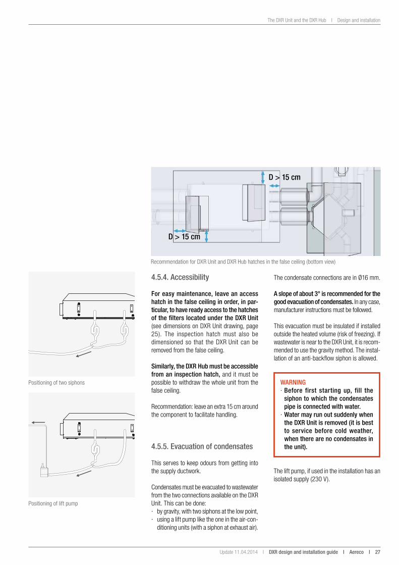
Recommendation for DXR Unit and DXR Hub hatches in the false ceiling (bottom view)
4.5.4. accessibility
For easy maintenance, leave an access hatch in the false ceiling in order, in par-ticular, to have ready access to the hatches of the filters located under the DXR unit (see dimensions on DXR Unit drawing, page 25). The inspection hatch must also be dimensioned so that the DXR Unit can be removed from the false ceiling.
similarly, the DXR Hub must be accessible from an inspection hatch, and it must be possible to withdraw the whole unit from the false ceiling.
Recommendation: leave an extra 15 cm around the component to facilitate handling.
4.5.5. evacuation of condensates
This serves to keep odours from getting into the supply ductwork.
Condensates must be evacuated to wastewater from the two connections available on the DXR Unit. This can be done: · by gravity, with two siphons at the low point, · using a lift pump like the one in the air-con-
ditioning units (with a siphon at exhaust air).
Positioning of two siphons
Positioning of lift pump
WaRning · Before first starting up, fill the siphon to which the condensates pipe is connected with water.
· Water may run out suddenly when the DXR unit is removed (it is best to service before cold weather, when there are no condensates in the unit).
The lift pump, if used in the installation has an isolated supply (230 V).
D > 15 cm
D > 15 cm
The condensate connections are in Ø16 mm.
a slope of about 3° is recommended for the good evacuation of condensates. In any case, manufacturer instructions must be followed.
This evacuation must be insulated if installed outside the heated volume (risk of freezing). If wastewater is near to the DXR Unit, it is recom-mended to use the gravity method. The instal-lation of an anti-backflow siphon is allowed.
28 i aereco i DXR design and installation guide I Update 11.04.2014 I
Design and installation I The DXR Unit and the DXR Hub
DXR Unit DXR HubRJ45
230 VAC
Example of studs
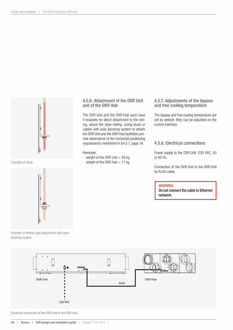
4.5.6. attachment of the DXR unit and of the DXR Hub
The DXR Unit and the DXR Hub each have 4 brackets for direct attachment to the ceil-ing, above the false ceiling. Using studs or cables with auto-blocking system to attach the DXR Unit and the DXR Hub facilitates pre-cise observance of the horizontal positioning requirements mentioned in §4.5.1, page 24.
Reminder: · weight of the DXR Unit = 40 kg · weight of the DXR Hub = 11 kg
Example of flexible type attachment with auto-blocking system
Electrical connection of the DXR Unit to the DXR Hub
4.5.7. adjustments of the bypass and free cooling temperature
The bypass and free cooling temperature are set by default; they can be adjusted on the control interface.
4.5.8. electrical connections
Power supply to the DXR Unit: 230 VAC, 50 or 60 Hz.
Connection of the DXR Hub to the DXR Unit by RJ45 cable.
WaRningDo not connect the cable to ethernet network.
Update 11.04.2014 I DXR design and installation guide i aereco i 29
The ducts I Design and installation
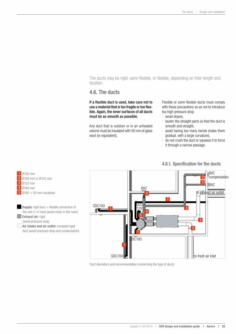
The ducts may be rigid, semi-flexible, or flexible, depending on their length and location.
4.6. the ducts
if a flexible duct is used, take care not to use a material that is too fragile or too flex-ible. again, the inner surfaces of all ducts must be as smooth as possible.
Any duct that is outdoor or in an unheated volume must be insulated with 50 mm of glass wool (or equivalent).
Duct diameters and recommendation concerning the type of ducts
1
1
1
1
22
2
3
34
5
5
1 Ø100 mm2 Ø100 mm or Ø125 mm3 Ø125 mm4 Ø160 mm5 Ø160 + 50 mm insulation
SDC100 SDC 125
SDC100
SDC100
BXCBXC
BXC compensation
to exhaust air outlet
to fresh air inlet
Flexible or semi-flexible ducts must comply with these precautions so as not to introduce too high pressure drop: · avoid slopes, · tauten the straight parts so that the duct is
smooth and straight, · avoid having too many bends (make them
gradual, with a large curvature), · do not crush the duct or squeeze it to force
it through a narrow passage.
4.6.1. specification for the ducts
supply: rigid duct + flexible connection to the unit (1 m max) (avoid noise in the room)
exhaust air: rigid (avoid pressure drop)
air intake and air outlet: insulated rigid duct (avoid pressure drop and condensation)
30 i aereco i DXR design and installation guide I Update 11.04.2014 I
Design and installation I The ducts
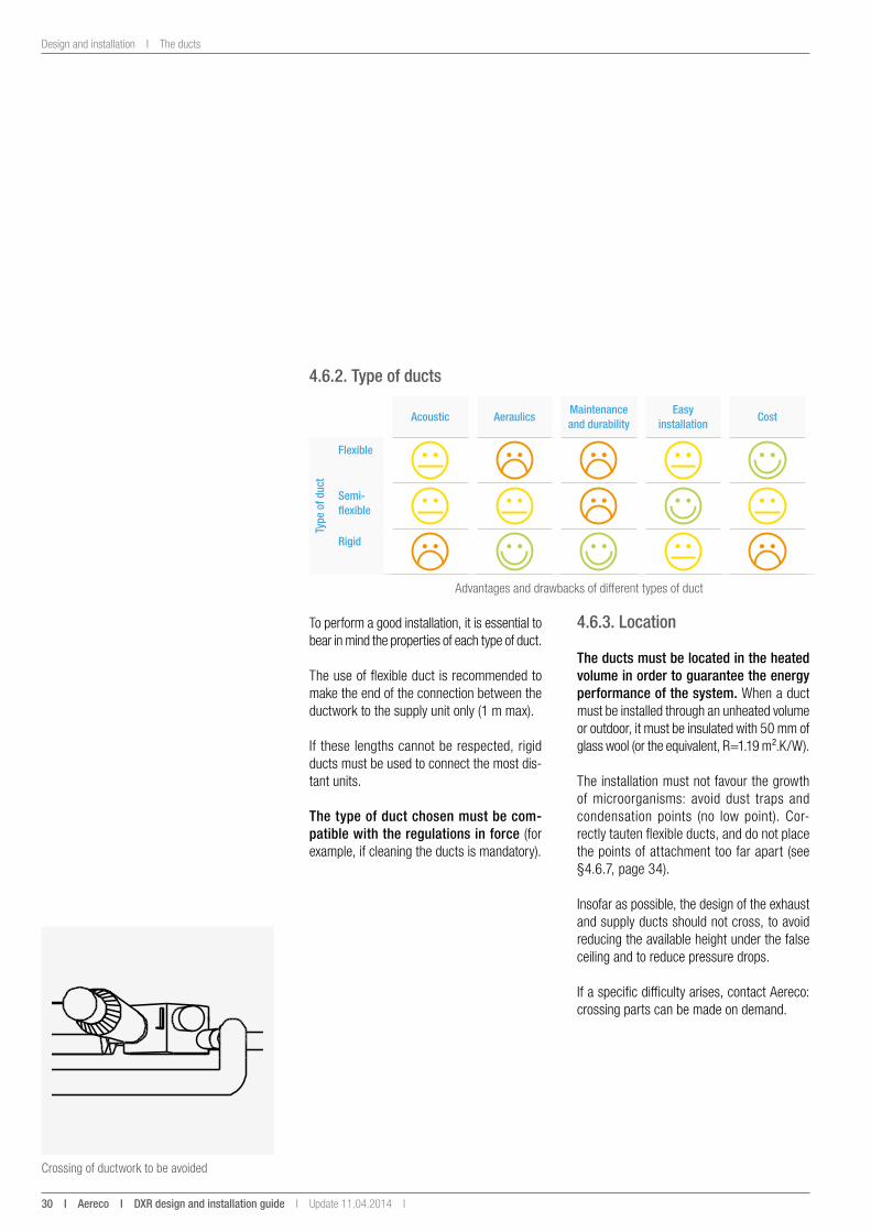
4.6.2. type of ducts
acoustic aeraulicsmaintenance and durability
easy installation
Cost
type
of d
uct
Flexible
semi-flexible
Rigid
Crossing of ductwork to be avoided
Advantages and drawbacks of different types of duct
To perform a good installation, it is essential to bear in mind the properties of each type of duct.
The use of flexible duct is recommended to make the end of the connection between the ductwork to the supply unit only (1 m max).
If these lengths cannot be respected, rigid ducts must be used to connect the most dis-tant units.
the type of duct chosen must be com-patible with the regulations in force (for example, if cleaning the ducts is mandatory).
4.6.3. location
the ducts must be located in the heated volume in order to guarantee the energy performance of the system. When a duct must be installed through an unheated volume or outdoor, it must be insulated with 50 mm of glass wool (or the equivalent, R=1.19 m².K/W).
The installation must not favour the growth of microorganisms: avoid dust traps and condensation points (no low point). Cor-rectly tauten flexible ducts, and do not place the points of attachment too far apart (see §4.6.7, page 34).
Insofar as possible, the design of the exhaust and supply ducts should not cross, to avoid reducing the available height under the false ceiling and to reduce pressure drops.
If a specific difficulty arises, contact Aereco: crossing parts can be made on demand.
Update 11.04.2014 I DXR design and installation guide i aereco i 31
The ducts I Design and installation
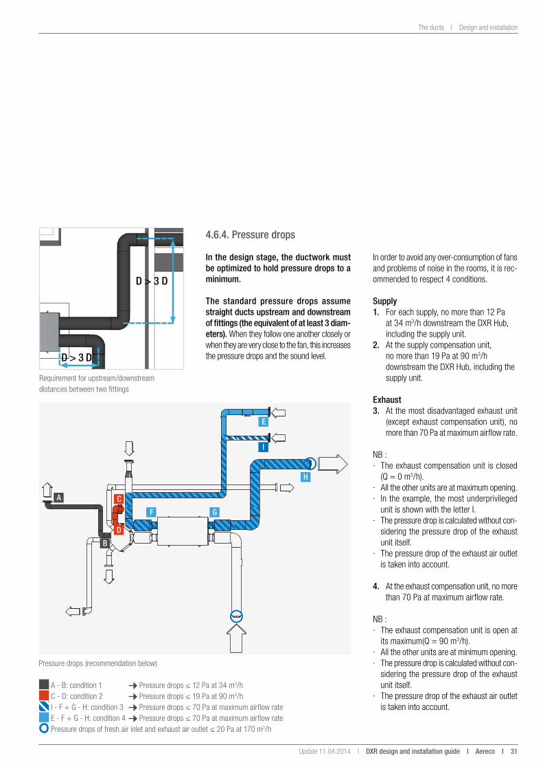
4.6.4. Pressure drops
in the design stage, the ductwork must be optimized to hold pressure drops to a minimum.
the standard pressure drops assume straight ducts upstream and downstream of fittings (the equivalent of at least 3 diam-eters). When they follow one another closely or when they are very close to the fan, this increases the pressure drops and the sound level.
In order to avoid any over-consumption of fans and problems of noise in the rooms, it is rec-ommended to respect 4 conditions.
supply1. For each supply, no more than 12 Pa
at 34 m3/h downstream the DXR Hub, including the supply unit.
2. At the supply compensation unit, no more than 19 Pa at 90 m3/h downstream the DXR Hub, including the supply unit.
exhaust3. At the most disadvantaged exhaust unit
(except exhaust compensation unit), no more than 70 Pa at maximum airflow rate.
NB : · The exhaust compensation unit is closed
(Q = 0 m3/h). · All the other units are at maximum opening. · In the example, the most underprivileged
unit is shown with the letter I. · The pressure drop is calculated without con-
sidering the pressure drop of the exhaust unit itself.
· The pressure drop of the exhaust air outlet is taken into account.
4. At the exhaust compensation unit, no more than 70 Pa at maximum airflow rate.
NB : · The exhaust compensation unit is open at
its maximum(Q = 90 m3/h). · All the other units are at minimum opening. · The pressure drop is calculated without con-
sidering the pressure drop of the exhaust unit itself.
· The pressure drop of the exhaust air outlet is taken into account.
Requirement for upstream/downstream distances between two fittings
D > 3 D
D > 3 D
a
B
C
F
e
g
H
i
D
Pressure drops (recommendation below)
A - B: condition 1 Pressure drops ≤ 12 Pa at 34 m3/h C - D: condition 2 Pressure drops ≤ 19 Pa at 90 m3/h I - F + G - H: condition 3 Pressure drops ≤ 70 Pa at maximum airflow rate E - F + G - H: condition 4 Pressure drops ≤ 70 Pa at maximum airflow rate Pressure drops of fresh air inlet and exhaust air outlet ≤ 20 Pa at 170 m3/h
32 i aereco i DXR design and installation guide I Update 11.04.2014 I
Design and installation I The ducts
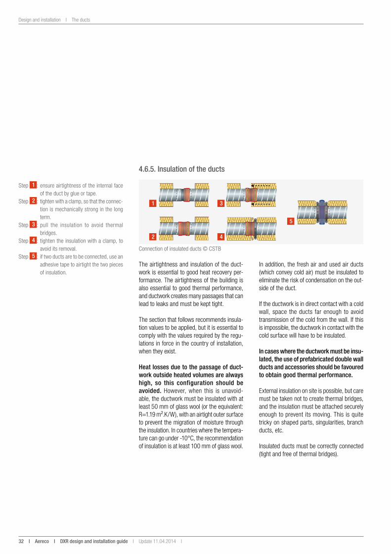
4.6.5. insulation of the ducts
Connection of insulated ducts © CSTB
1 3
2 4
5
Step 1 : ensure airtightness of the internal face of the duct by glue or tape.
Step 2 : tighten with a clamp, so that the connec-tion is mechanically strong in the long term.
Step 3 : pull the insulation to avoid thermal bridges.
Step 4 : tighten the insulation with a clamp, to avoid its removal.
Step 5 : if two ducts are to be connected, use an adhesive tape to airtight the two pieces of insulation.
The airtightness and insulation of the duct-work is essential to good heat recovery per-formance. The airtightness of the building is also essential to good thermal performance, and ductwork creates many passages that can lead to leaks and must be kept tight.
The section that follows recommends insula-tion values to be applied, but it is essential to comply with the values required by the regu-lations in force in the country of installation, when they exist.
Heat losses due to the passage of duct-work outside heated volumes are always high, so this configuration should be avoided. However, when this is unavoid-able, the ductwork must be insulated with at least 50 mm of glass wool (or the equivalent: R=1.19 m².K/W), with an airtight outer surface to prevent the migration of moisture through the insulation. In countries where the tempera-ture can go under -10°C, the recommendation of insulation is at least 100 mm of glass wool.
In addition, the fresh air and used air ducts (which convey cold air) must be insulated to eliminate the risk of condensation on the out-side of the duct.
If the ductwork is in direct contact with a cold wall, space the ducts far enough to avoid transmission of the cold from the wall. If this is impossible, the ductwork in contact with the cold surface will have to be insulated.
in cases where the ductwork must be insu-lated, the use of prefabricated double wall ducts and accessories should be favoured to obtain good thermal performance.
External insulation on site is possible, but care must be taken not to create thermal bridges, and the insulation must be attached securely enough to prevent its moving. This is quite tricky on shaped parts, singularities, branch ducts, etc.
Insulated ducts must be correctly connected (tight and free of thermal bridges).
Update 11.04.2014 I DXR design and installation guide i aereco i 33
The ducts I Design and installation
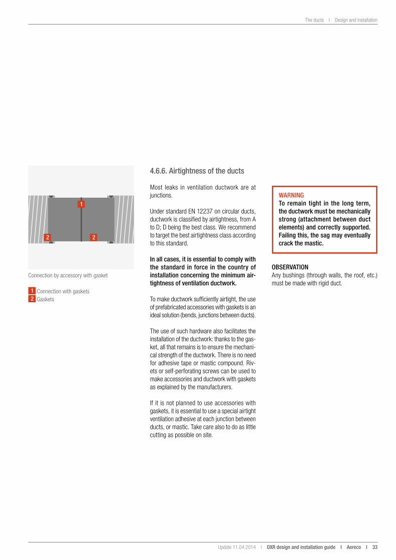
4.6.6. airtightness of the ducts
Most leaks in ventilation ductwork are at junctions.
Under standard EN 12237 on circular ducts, ductwork is classified by airtightness, from A to D; D being the best class. We recommend to target the best airtightness class according to this standard.
in all cases, it is essential to comply with the standard in force in the country of installation concerning the minimum air-tightness of ventilation ductwork.
To make ductwork sufficiently airtight, the use of prefabricated accessories with gaskets is an ideal solution (bends, junctions between ducts).
The use of such hardware also facilitates the installation of the ductwork: thanks to the gas-ket, all that remains is to ensure the mechani-cal strength of the ductwork. There is no need for adhesive tape or mastic compound. Riv-ets or self-perforating screws can be used to make accessories and ductwork with gaskets as explained by the manufacturers.
If it is not planned to use accessories with gaskets, it is essential to use a special airtight ventilation adhesive at each junction between ducts, or mastic. Take care also to do as little cutting as possible on site.
Connection by accessory with gasket
1
2 2
1 Connection with gaskets2 Gaskets
WaRningto remain tight in the long term, the ductwork must be mechanically strong (attachment between duct elements) and correctly supported. Failing this, the sag may eventually crack the mastic.
oBseRvationAny bushings (through walls, the roof, etc.) must be made with rigid duct.
34 i aereco i DXR design and installation guide I Update 11.04.2014 I
Design and installation I The ducts
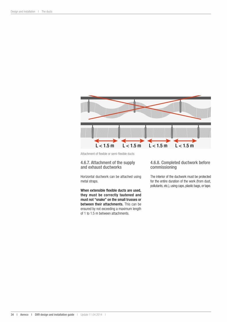
Attachment of flexible or semi-flexible ducts
l < 1.5 m l < 1.5 m l < 1.5 ml < 1.5 m
4.6.7. attachment of the supply and exhaust ductworks
Horizontal ductwork can be attached using metal straps.
When extensible flexible ducts are used, they must be correctly tautened and must not “snake” on the small trusses or between their attachments. This can be ensured by not exceeding a maximum length of 1 to 1.5 m between attachments.
4.6.8. Completed ductwork before commissioning
The interior of the ductwork must be protected for the entire duration of the work (from dust, pollutants, etc.), using caps, plastic bags, or tape.

Update 11.04.2014 I DXR design and installation guide i aereco i 35
The exhaust compensation valve I Design and installation
The exhaust compensation valve is a key part of the DXR heat recovery system. Its purpose is to provide an exhaust airflow to balance the airflow rate if the exhaust airflow is lower than the supply airflow.
4.7. the exhaust compensation valve
Exhaust compensation valve
247
235
Ø125
mm
Positioning of the exhaust compensation valve with access hatch
D > 38 cm D > 38 cm
4.7.1. location and positioning of the valve
The valve is located in the final duct that serves the exhaust compensation unit (in the kitchen). Its is therefore Ø125 mm. This product is spe-cific to Aereco.
The valve can be positioned in any direction, the maximum length being 247 mm (valve + regulator). However, attention must be paid to the direction of airflow in the valve: an arrow marked on the valve indicates the correct position.
The valve must be placed in the duct, at a minimum distance equivalent to 3 diameters (38 cm for a Ø125 mm duct) from any fittings, and from the compensation unit.
In addition, there must be an inspection hatch to access the valve for maintenance.
4.7.2. electrical connection
The compensation valve is connected to the DXR Unit by a RJ45 wire. The power supply of the valve comes directly from the DXR Unit through this wire.
36 i aereco i DXR design and installation guide I Update 11.04.2014 I
Design and installation I Defrosting
The defrosting warms the air before entering the heat recovery system to eliminate any worries about frost, impairing heat recovery performance and air quality.
4.8. Defrosting
4.8.1. anti-frost operating
The DXR includes a specific anti-frost strategy based on the supply airflow regulation. How-ever, if the number of consecutive hours or days when outdoors temperature is under -7°C is high, it is recommended to use a defrosting device (additional pre-heating resistance).
When using the DXR without the additional defrosting, the supply air fan is switched off and the extract air fan remains active, in order to warm up the heat exchanger. Be careful, very often, this type of strategy does not comply with an open fireplace. Make sure that you comply with the standard in force in the country of installation.
When the optional resistance is used, this frost strategy is not active anymore. A specific strat-egy is used, in order to avoid the frosting of the heat recovery. The system doesn’t need any additional preheating device, as the sup-plied air has a temperature of at least 14°C (defrosting started at -7°C).
note: · The DXR has been specially designed to
work with the defrosting provided by Aereco (defrost strategy specific to DXR system, and adapted diameter). Besides, it has been CEM certified with the DXR.
· Using another defrosting can lead to serious problems of functioning and degrade the security of the system.
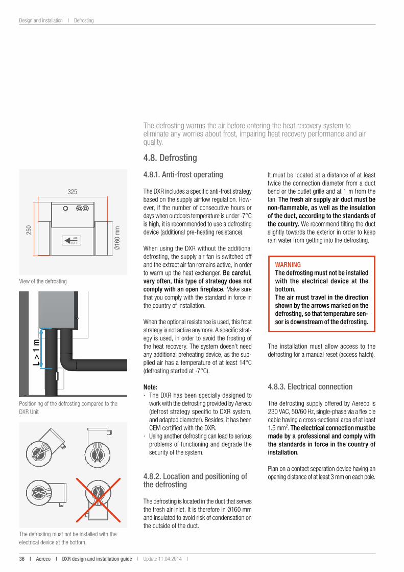
4.8.2. location and positioning of the defrosting
The defrosting is located in the duct that serves the fresh air inlet. It is therefore in Ø160 mm and insulated to avoid risk of condensation on the outside of the duct.
325
250
Ø160
mm
View of the defrosting
The defrosting must not be installed with the electrical device at the bottom.
Positioning of the defrosting compared to the DXR Unit
It must be located at a distance of at least twice the connection diameter from a duct bend or the outlet grille and at 1 m from the fan. the fresh air supply air duct must be non-flammable, as well as the insulation of the duct, according to the standards of the country. We recommend tilting the duct slightly towards the exterior in order to keep rain water from getting into the defrosting.
l >
1 m
WaRningthe defrosting must not be installed with the electrical device at the bottom.the air must travel in the direction shown by the arrows marked on the defrosting, so that temperature sen-sor is downstream of the defrosting.
The installation must allow access to the defrosting for a manual reset (access hatch).
4.8.3. electrical connection
The defrosting supply offered by Aereco is 230 VAC, 50/60 Hz, single-phase via a flexible cable having a cross-sectional area of at least 1.5 mm². the electrical connection must be made by a professional and comply with the standards in force in the country of installation.
Plan on a contact separation device having an opening distance of at least 3 mm on each pole.
Update 11.04.2014 I DXR design and installation guide i aereco i 37
The DXR user interface I Design and installation
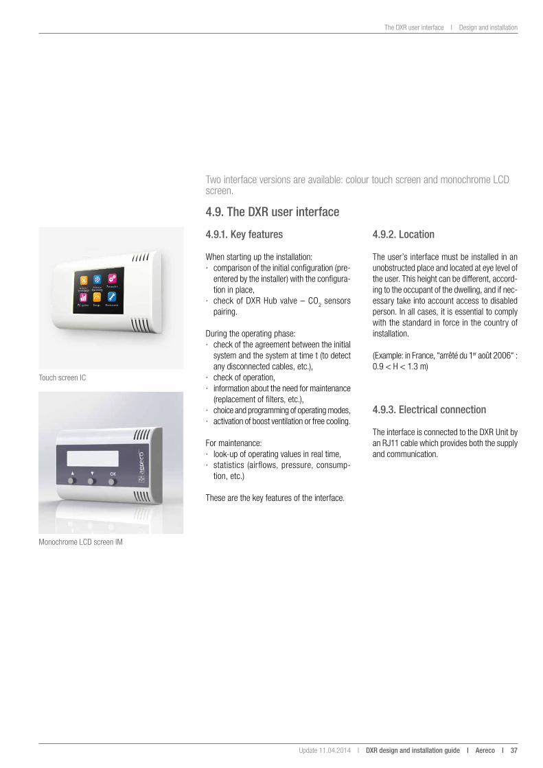
Two interface versions are available: colour touch screen and monochrome LCD screen.
4.9. the DXR user interface
4.9.1. Key features
When starting up the installation: · comparison of the initial configuration (pre-
entered by the installer) with the configura-tion in place,
· check of DXR Hub valve – CO2 sensors pairing.
During the operating phase: · check of the agreement between the initial
system and the system at time t (to detect any disconnected cables, etc.),
· check of operation, · information about the need for maintenance
(replacement of filters, etc.), · choice and programming of operating modes, · activation of boost ventilation or free cooling.
For maintenance: · look-up of operating values in real time, · statistics (airflows, pressure, consump-
tion, etc.)
These are the key features of the interface.
Touch screen IC
Monochrome LCD screen IM
4.9.2. location
The user’s interface must be installed in an unobstructed place and located at eye level of the user. This height can be different, accord-ing to the occupant of the dwelling, and if nec-essary take into account access to disabled person. In all cases, it is essential to comply with the standard in force in the country of installation.
(Example: in France, “arrêté du 1er août 2006“ : 0.9 < H < 1.3 m)
4.9.3. electrical connection
The interface is connected to the DXR Unit by an RJ11 cable which provides both the supply and communication.
38 i aereco i DXR design and installation guide I Update 11.04.2014 I
Certifications
5. CeRtiFiCations
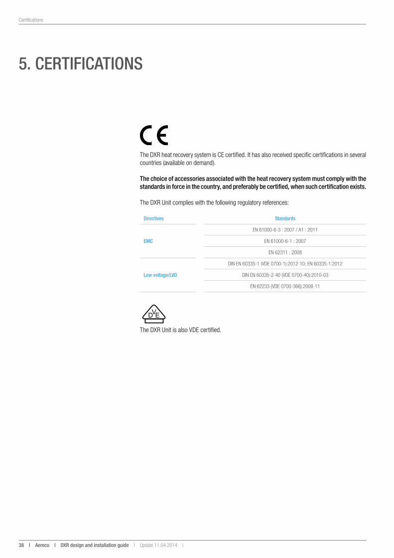
The DXR heat recovery system is CE certified. It has also received specific certifications in several countries (available on demand).
the choice of accessories associated with the heat recovery system must comply with the standards in force in the country, and preferably be certified, when such certification exists.
The DXR Unit complies with the following regulatory references:
Directives standards
emC
EN 61000-6-3 : 2007 / A1 : 2011
EN 61000-6-1 : 2007
EN 62311 : 2008
low voltage/lvD
DIN EN 60335-1 (VDE 0700-1):2012-10; EN 60335-1:2012
DIN EN 60335-2-40 (VDE 0700-40):2010-03
EN 62233 (VDE 0700-366):2008-11
The DXR Unit is also VDE certified.
Update 11.04.2014 I DXR design and installation guide i aereco i 39
Fire protection
6. FiRe PRoteCtion
The installation must comply with the fire protection standards in force in the country concerned, and that apply to single-dwelling ventilation systems.
40 i aereco i DXR design and installation guide I Update 11.04.2014 I
Anticipate maintenance in the design
7. antiCiPate maintenanCe in tHe Design
Several points must guide the design of the ventilation ductwork to ease the maintenance: · mini-ducts should be avoided because they are difficult to clean; · flexible ducts are also less than ideal for maintenance because they do not allow the
passage of a rotary brush; · a drawing of the ductwork is essential, to direct the rotary brush and allow maintenance
of the ductwork; · access hatches in the ventilation ductwork facilitate servicing(4); · the heat recovery system must be readily accessible to allow proper maintenance of the
filters, and also any servicing necessary on the heat exhanger and the fans.
Enough space must be left around the components (units, etc.) for servicing, and means of access must be easy to identify, lighted, and not be a hazard for the people doing the work.
(4) It is however difficult to impose them, in particular for reasons of cost and appearance.3
Update 11.04.2014 I DXR design and installation guide i aereco i 41
Creation of a technical file
8. CReation oF a teCHniCal File
The technical file is the document that records the results of the design and dimensioning studies of the installation and is used to check the installation. Ideally, the technical file will include the following items: · the layout and dimensioning:
- a wireline diagram of the ductwork,- the location and aeraulic characteristics of the supply (airflow rates),- the location (number, location, etc.), type (grilles, clearances, etc.), and dimensioning
of air passage,- the location and aeraulic characteristics of the exhaust (airflow rates),- the type (flexible or rigid) and characteristics (material, thermal and acoustic proper-
ties) of the connecting ducts,- the dimensions (length, diameter, cross-sectional area, etc.) of the duct elements.
· drawings with dimensions, · calculation data (acoustic, for example), · the identification, by the commercial reference, of all components used.
the technical file is essential for the life and maintenance of the installation.
42 i aereco i DXR design and installation guide I Update 11.04.2014 I
Acceptance of works I Visual inspection
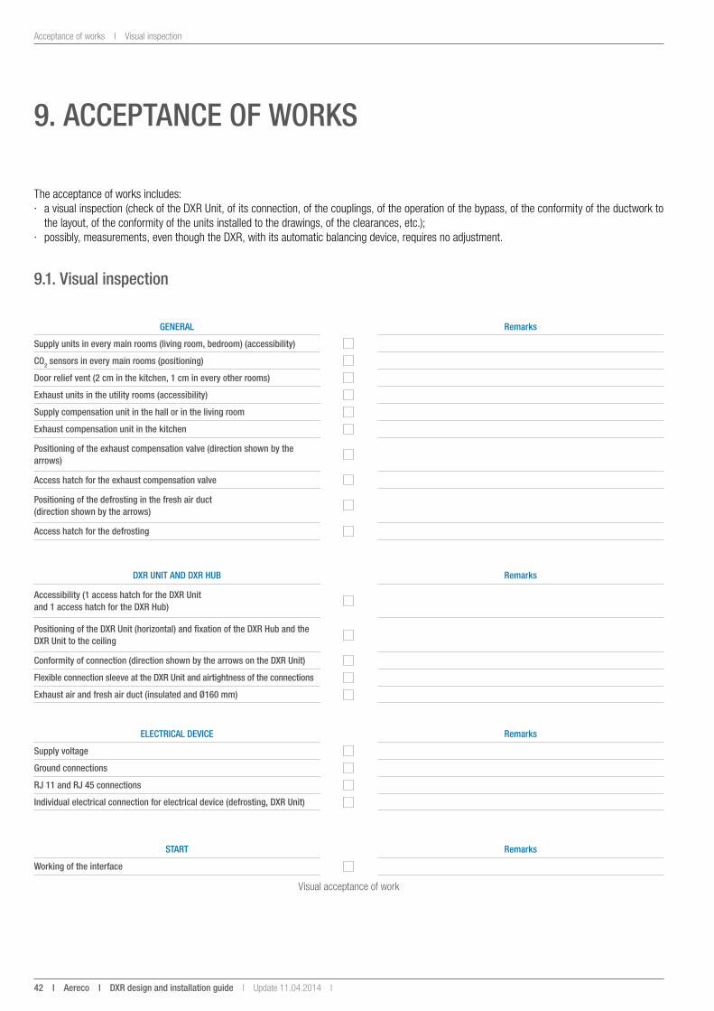
9. aCCePtanCe oF WoRKs
The acceptance of works includes: · a visual inspection (check of the DXR Unit, of its connection, of the couplings, of the operation of the bypass, of the conformity of the ductwork to
the layout, of the conformity of the units installed to the drawings, of the clearances, etc.); · possibly, measurements, even though the DXR, with its automatic balancing device, requires no adjustment.
9.1. visual inspection
geneRal Remarks
supply units in every main rooms (living room, bedroom) (accessibility)
Co2 sensors in every main rooms (positioning)
Door relief vent (2 cm in the kitchen, 1 cm in every other rooms)
exhaust units in the utility rooms (accessibility)
supply compensation unit in the hall or in the living room
exhaust compensation unit in the kitchen
Positioning of the exhaust compensation valve (direction shown by the arrows)
access hatch for the exhaust compensation valve
Positioning of the defrosting in the fresh air duct (direction shown by the arrows)
access hatch for the defrosting
DXR unit anD DXR HuB Remarks
accessibility (1 access hatch for the DXR unit and 1 access hatch for the DXR Hub)
Positioning of the DXR unit (horizontal) and fixation of the DXR Hub and the DXR unit to the ceiling
Conformity of connection (direction shown by the arrows on the DXR unit)
Flexible connection sleeve at the DXR unit and airtightness of the connections
exhaust air and fresh air duct (insulated and Ø160 mm)
eleCtRiCal DeviCe Remarks
supply voltage
ground connections
RJ 11 and RJ 45 connections
individual electrical connection for electrical device (defrosting, DXR unit)
staRt Remarks
Working of the interface
Visual acceptance of work
Update 11.04.2014 I DXR design and installation guide i aereco i 43
Measurements I Acceptance of works
9.2. measurements
If some measurements are planned on the project, it is recommended to measure for acceptance of work: · the airflow rates and pressures at the exhaust and supply units, · the airflow rates at the fresh air intake and the used air discharge, · possibly, the sound level in the main rooms and very close to the fans, · check the modulation of the airflow.
44 i aereco i DXR design and installation guide I Update 11.04.2014 I
Servicing and maintenance
10. seRviCing anD maintenanCe
Maintenance of ventilation installations serves to avoid: · microbial contamination of the installations, with consequences on comfort and health; the impact of such contamination is aggravated in an air supply, · loss of aeraulic performance through high pressure drops, · noise (from a too high air speed, and from high speed rotation of fan due to clogged filter)
Regular maintenance of the installation must be planned.
Frequency maintenance
when the alarm indicates itFilters: replace the filters when the alarm indicates it, then initialize the new filters. It is essential to replace all of the filters at the same time.
once a year
Fresh air inlet and exhaust air outlet: check the unobstructed passage of air (no dead leaves, no snow).
Supply and exhaust units: cleaning as recommended by the manufacturer (this part can be done by the occupant).
Evacuation of condensates: check that the system is not obstructed by impurities.WaRning: Plan replacement of the condensates evacuation pump according to the life span announced by the supplier.
Ductwork: check and cleaning if the ductwork is obstructed.
once every 5 years
Exchanger: check the exchanger and clean it (withdraw the exchanger and wash it with soapy water, taking care not to twist the aluminium blades. The exchanger must be perfectly dry before it is put back into the heat recovery system).In all cases, it is essential to comply with the standard in force in the country of the installation.
Fans: · check the blades, · check and possibly replace the antivibration sleeve and the collars;
Detail of maintenance operations essential to the proper operation of the DXR
Update 11.04.2014 I DXR design and installation guide i aereco i 45
Technical characteristics of the DXR I Appendices
aPPenDiCes
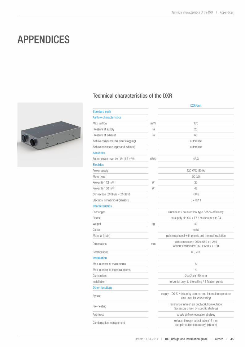
technical characteristics of the DXR
DXR unit
standard code
airflow characteristics
Max. airflow m3/h 170
Pressure at supply Pa 25
Pressure at exhaust Pa 60
Airflow compensation (filter clogging) automatic
Airflow balance (supply and exhaust) automatic
acoustics
Sound power level Lw @ 165 m3/h dB(A) 46.3
electrics
Power supply 230 VAC, 50 Hz
Motor type EC (x2)
Power @ 112 m3/h W 30
Power @ 160 m3/h W 42
Connection DXR Hub - DXR Unit RJ45
Electrical connections (sensors) 5 x RJ11
Characteristics
Exchanger aluminium / counter flow type / 85 % efficiency
Filters on supply air: G4 + F7 / on exhaust air: G4
Weight kg 40
Colour metal
Material (main) galvanised steel with phonic and thermal insulation
Dimensions mmwith connectors: 260 x 650 x 1 240
without connectors: 260 x 650 x 1 160
Certifications CE, VDE
installation
Max. number of main rooms 5
Max. number of technical rooms 4
Connections 2 x (2 x ø160 mm)
Installation horizontal only, to the ceiling / 4 fixation points
other functions
Bypasssupply: 100 % / driven by external and internal temperature
also used for free cooling
Pre-heatingresistance in fresh air ductwork from outside
(accessory driven by specific strategy)
Anti-frost supply airflow regulation strategy
Condensation managementexhaust through lateral tube ø16 mm pump in option (accessory) (ø6 mm)
46 i aereco i DXR design and installation guide I Update 11.04.2014 I
Appendices I Technical characteristics of the DXR
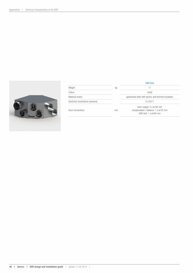
DXR Hub
Weight kg 11
Colour metal
Material (main) galvanised steel with phonic and thermal insulation
Electrical connections (sensors) 5 x RJ11
Duct connections mmroom supply: 5 x ø100 mm
compensation / balance: 1 x ø125 mm DXR Unit: 1 x ø160 mm
Update 11.04.2014 I DXR design and installation guide i aereco i 47
Technical characteristics of the DXR I Appendices
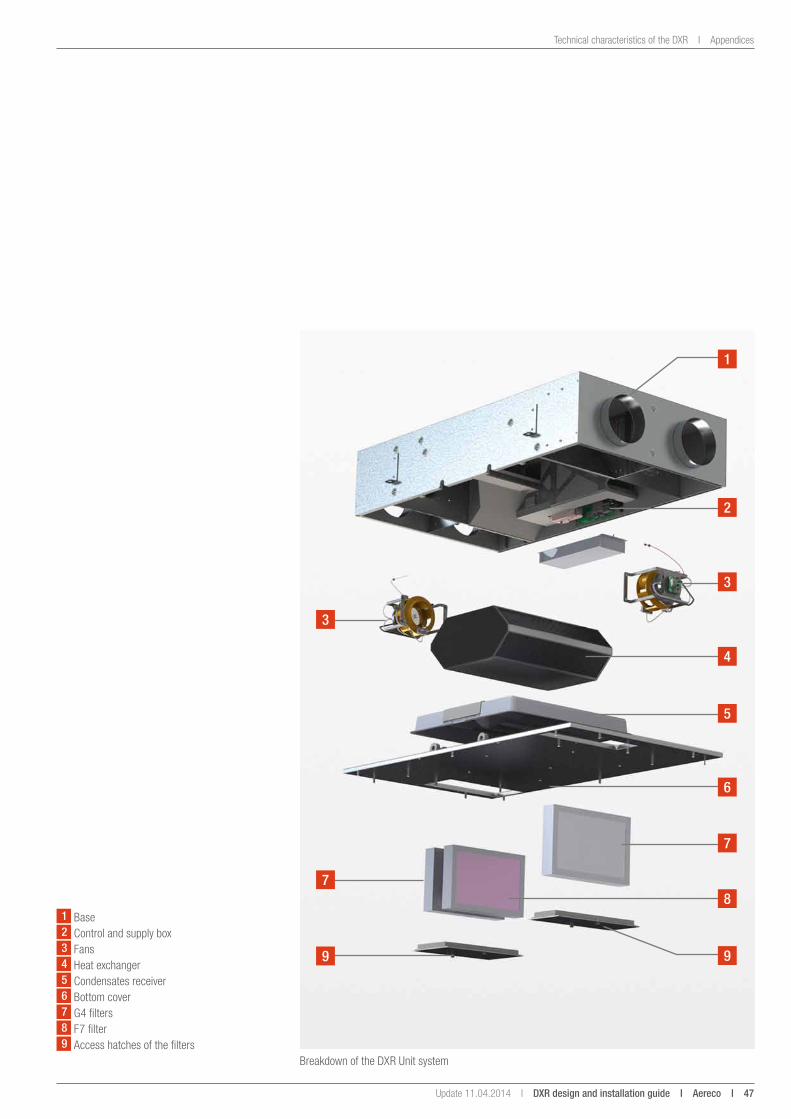
Breakdown of the DXR Unit system
1
2
3
3
7
4
5
6
7
8
99
1 Base2 Control and supply box3 Fans4 Heat exchanger5 Condensates receiver6 Bottom cover7 G4 filters8 F7 filter9 Access hatches of the filters
48 i aereco i DXR design and installation guide I Update 11.04.2014 I
Appendices I Electrical connections
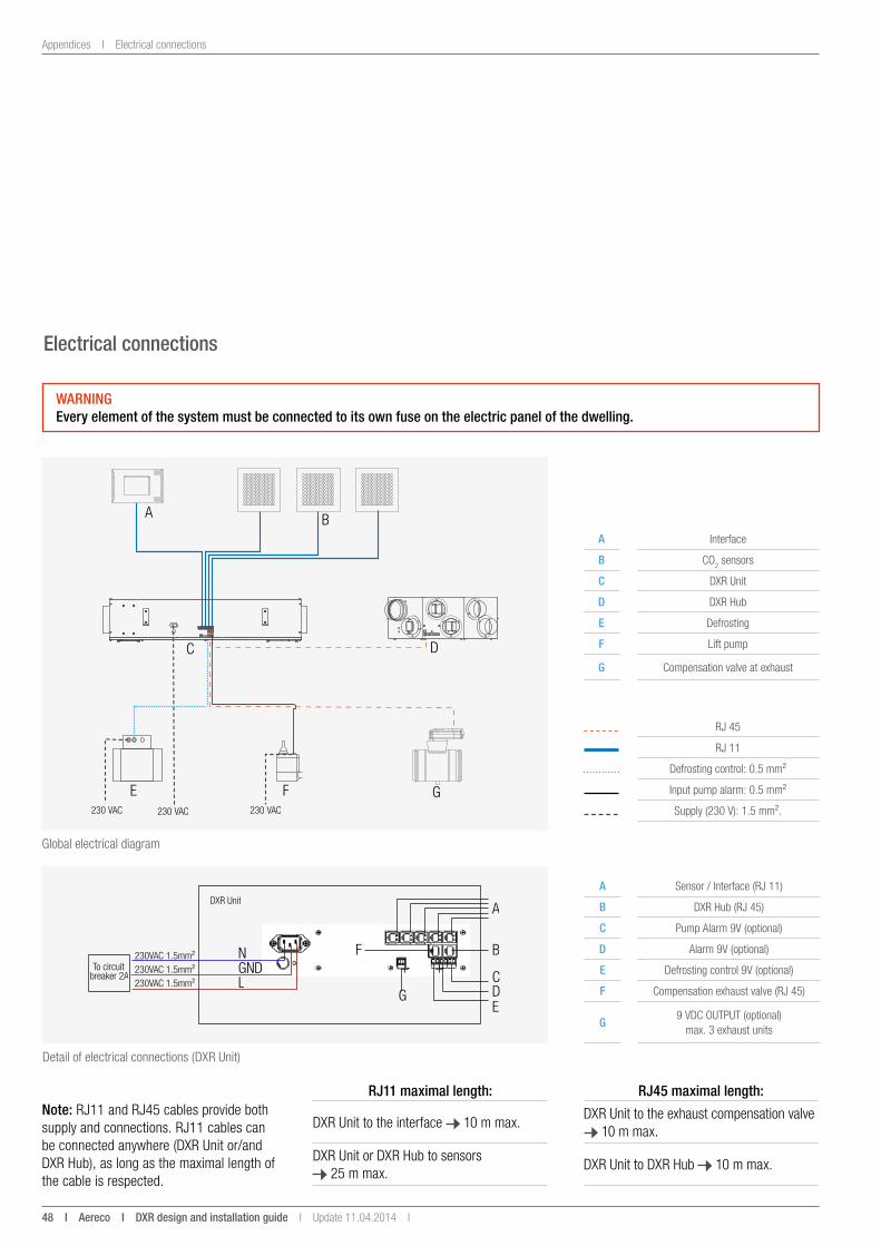
Global electrical diagram
electrical connections
BA
C D
E F G230 VAC 230 VAC 230 VAC
Detail of electrical connections (DXR Unit)
WaRningevery element of the system must be connected to its own fuse on the electric panel of the dwelling.
a Interface
B CO2 sensors
C DXR Unit
D DXR Hub
e Defrosting
F Lift pump
g Compensation valve at exhaust
RJ 45
RJ 11
Defrosting control: 0.5 mm²
Input pump alarm: 0.5 mm²
Supply (230 V): 1.5 mm².
a Sensor / Interface (RJ 11)
B DXR Hub (RJ 45)
C Pump Alarm 9V (optional)
D Alarm 9V (optional)
e Defrosting control 9V (optional)
F Compensation exhaust valve (RJ 45)
g9 VDC OUTPUT (optional)
max. 3 exhaust units
DXR Unit
+ -To circuit breaker 2A
N GNDL
A
B
CDE
+ -
G
F
230VAC 1.5mm²230VAC 1.5mm²230VAC 1.5mm²
note: RJ11 and RJ45 cables provide both supply and connections. RJ11 cables can be connected anywhere (DXR Unit or/and DXR Hub), as long as the maximal length of the cable is respected.
RJ11 maximal length: RJ45 maximal length:
DXR Unit to the interface 10 m max.DXR Unit to the exhaust compensation valve
10 m max.
DXR Unit or DXR Hub to sensors 25 m max.
DXR Unit to DXR Hub 10 m max.

Copyright © aereco. all rights reserved, reproduction prohibited.
The data and pictures in this document are not binding and are subject to change without notice.
FLY5
63GB
_v2
– Co
pyrig
ht A
erec
o –
ICop
yrig
ht A
erec
o. Im
ages
: co
pyrig
ht A
erec
o, C
STB
– Al
l dat
a an
d pi
ctur
es in
this
docu
men
t are
non
con
tract
ual a
nd a
re s
ubje
ct to
cha
nge
with
out p
rior n
otice
.
aereco s.a.62 rue de Lamirault – Collégien – 77615 MARNE LA VALLEE CEDEX 3 – FRANCE – tel. +33 1 60 06 26 63 – fax +33 1 64 80 47 26
www.aereco.com