Embed Size (px)
Citation preview

Dyna Doctor Tool Operation manual for IES/DI/SDI Modify for RAS Inverter edition
TCTC QAM Page 1
Dyna Doctor Tool Operation Manual for RAS Inverter model.
This tool Toshiba Carrier company we are provide service tool for support sale entity or service team use
this tool software and hardware for connect with inverter unit to get the detail information of system during
operation / stand by that it collect data from sensor thermistor and other hardware / software processing
1. How to connect hardware to access data information from Inverter unit Service team need to provide
Dyna Doctor Kit as below model
2. Down load DDT program then installation in PC or laptop and activate program for ready to used.
How to connect DDT to CDU Inverter unit.
1) Turns it off power supply to unit, Ensure no power supply to unit when connect lead of DDT tool for
safety with device and service man.
2) Open the top cabinet, front cabinet and cover inverter unit to connect DDT kit device (Connector 6 pin)
with SWRT connector housing on CDU PCB of each type as below table.
No. PCB type Model apply Reference connector position SWRT connector
1 WP-030
RAS-07, 10, 13S3AV RAS-10N3ACV RAS-10N3AV RAS-13, 16,18, 22, 24BAV RAS-13, 16,18, 22, 24BACV RAS-16, 18,22,24J2AVG RAS-16, 18,22,24,25PACVG RAS-16, 18,22,24,25PAVSG RAS-16, 18,22,24TAVG RAS-18, 24, 28U2ACV RAS-25, 35PAVPG RAS-H13, H18J2ACV RAS-H18, H24PACVG RAS-H24BACV RAS-H18, H24U2ACV RAV-GM301AT RAV-GM401AT
CN82
TCB-DK01SS-E: CNV2-3.3V By this tool it can connect USB port of Laptop directly. When you connect USB port, you must install USB Driver. This driver can download below URL. FTDI (Future Technology Devices International Ltd.). URL : http://www.ftdichip.com/Drivers/VCP.htm
Device Name : FT232R
Figure 1.1 DDT
hardware
Dyna Doctor Tool Operation manual for IES/DI/SDI Modify for RAS Inverter edition
TCTC QAM Page 2
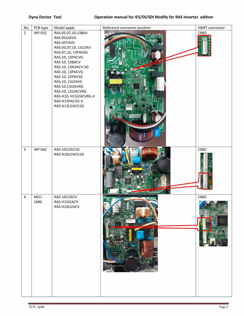
No. PCB type Model apply Reference connector position SWRT connector
2 WP-032 RAS-05,07,10,13BAV RAS-05J2AVG RAS-05TAVG RAS-05,07,10, 13U2AV RAS-07,10, 13PAVSG RAS-10, 13PACVG RAS-10, 13BACV RAS-10, 13N3ACV-SG RAS-10, 13PACVG RAS-10, 13PAVSG RAS-10, 13J2AVG RAS-10,13J2AVRG RAS-10, 13J2ACVRG RAS-H10, H13J2ACVRG-V RAS-H13PACVG-V RAS-H13U2ACV2G
CN82
3 WP-042 RAS-10U2ACVG RAS-H10U2ACV2G
CN82
4 MCC-1686
RAS-10U2ACV RAS-H10J2ACV RAS-H10U2ACV
CN82

Dyna Doctor Tool Operation manual for IES/DI/SDI Modify for RAS Inverter edition
TCTC QAM Page 3
No. PCB type Model apply Reference connector position SWRT connector
5 MCC-1571
RAS-24N3A RAV-SP804AT
CN800
6 MCC-1626
RAV-GExx01A8 RAV-GM11, 1401AT8 RAV-SM11, 1401AT8 RAV-TE1401A8
CN803
7 MCC-
1648
RAS-30PA RAV-GE2501AP RAV-GE3001AP RAV-GE3601AP RAV-TE1001AP RAV-TE1251AP RAV-GM1101AT RAV-GM1401AT RAV-SM1104AT RAV-SM1404AT
CN803
8 MCC-1731
RAV-SM1404ATP
CN803
9 WP-044 RAV-GE13,18,2401AP RAV-SM804ATP
CN804
10 MCC-1645
RAS-10,13,16G2AVP RAS-22, 24PAV RAS-25, 35S3AVP-ND RAV-GM561AT RAV-GM801AT
CN804

Dyna Doctor Tool Operation manual for IES/DI/SDI Modify for RAS Inverter edition
TCTC QAM Page 4
No. PCB type Model apply Reference connector position SWRT connector
10 MCC-1713
RAV-GP561AT
CN804
11 MCC-1656
RAS-18N3A RAS-22N3A RAV-SM304AT RAV-SM404AT RAV-TE401AP
CN804
Table 2.2.1 Location of SWRT of each PCB type
3) Connect DDT USB lead or RS232 to PCB and computer (Check sure computer have installation diver
before if no please down load as link URL above and installation for ready to used).
4) Power supply on to standby or operate start.
3. How to used DDT for RAS (Inverter ) model
1. Installation software or upgrade on PC and register program for continues use in case of service man
never installation before.
2. Set shortcut then double click at shortcut icon as below to open program or click start from window
bar.
or Figure 3.2.1 How to open program
3. Click OK after window Welcome to Dyna Doctor display
Figure 3.3.1 Software version
Remark:
This software need for register or activate within 30 Day for new user, if overdue program
cannot use, so please execute license before date of expiration, In case of upgrade program not need
to do for execute license.

Dyna Doctor Tool Operation manual for IES/DI/SDI Modify for RAS Inverter edition
TCTC QAM Page 5
Figure 3.3.2 Message reminder
4. Select setting for monitor mode or history mode.
No. Monitor mode History mode
1
2 Select and setting as below. Model setting RAS (Inverter) Refrigerant R410A Maker TOSHIBA Model Export Unit type Single Mode Monitoring mode Comp port auto display*
Select and setting as below. Model setting RAS (Inverter) Refrigerant R410A Maker TOSHIBA Model Export Unit type Single Mode History mode
3 Select or click complete then click start Table 3.4.1 Main menu setting
*Comport Select port from USB Manager, if only one device connect program will auto display.
5. After click start window will change display as below.
Figure 3.5.1 Table data

Dyna Doctor Tool Operation manual for IES/DI/SDI Modify for RAS Inverter edition
TCTC QAM Page 6
6. How to record file, Click File Save data then select directory for record file.
Figure 3.6.1 How to record
Display will change as below then please set record interval for table data.
Figure 3.6.2 Time interval set
Click record start at red mark for start record, (Click = Pause record or click = Stop record.
7. Select directory for file for save, usually name will auto set by DDT software 190310_A.dat (19= Year
2019, 03= Month (Jan =01, Feb=02, Mar=03),10= date of record or service man can Make new file
name Up to they can understood then click Save.
Figure 3.7.1 How to save file
Display will change as below, during record symbols change from red to gray color.
Figure 3.7.2 Display symbols during record

Dyna Doctor Tool Operation manual for IES/DI/SDI Modify for RAS Inverter edition
TCTC QAM Page 7
8. During record service man can monitor Table, Map and Graph by click of each icons then
display will show as below.
Figure 3.8.1 Window of each display
9. How to change graph.
9.1) After click graph display graph will display as below picture.
Figure 3.9.1 Initial graph
9.2) Default factory setting no any item on graph then user need for addition items that they are
interesting to monitoring by click “Data select” for display and Interval(sec) then click OK
Can select max 8 items.
Suggest set Interval (Sec) same data table to match with number during display on window.
Figure 3.9.2 Data select for display trend
9.3 Scale setting by Click for scale setting as below.
Figure 3.9.3 Scale setting

Dyna Doctor Tool Operation manual for IES/DI/SDI Modify for RAS Inverter edition
TCTC QAM Page 8
4. How to check history file
4.1) Select model setting RAS (Inverter)
4.2) Select history mode then click start
Figure 4.2.1 Set display for history mode
4.3) Browse file name from directory folder that file record are keep then double click for file need for
open then click open and click “File Open” for start”
Figure 4.3.1 browse file for open
Figure 4.3.2 Select file for open
Figure 4.3.3 Cursor to slide for monitor
4.4) Display will show as below.
Items Table Map Graph
Display
Table 4.4.1 display of history

Dyna Doctor Tool Operation manual for IES/DI/SDI Modify for RAS Inverter edition
TCTC QAM Page 9
4.5) Trend graph when user open file need for adjust scale to match with time of each file from
recording and user can select or slide cursor to monitor number on the trend of graph as below.
Figure 4.5.1 Cursor slide on history control bar
4.6) Method for adjust scale when open new file.
4.6.1) Need for set scale to match with file update record.
No Items Figure Description
1 Graph after open file
Graph show in some area
2 Scale setting
If need to show with full trend need change setting X-Max from 9053
to 35674 then click OK trend graph will change as below.
3 Graph after scale setting
We can see trend of record with full time record.
Table 4.6.1 How to setting scale graph
4.6.2) In any open new file name or change file need to doing on detail of table 4.6.1
5. Wording definition on Table data
Unit No Items Meaning
Indoor
1 TA temp Room temperature (Return air to unit)
2 TC temp Coil temperature (Center of coil)
3 TCJ temp Coil temperature (Outlet)
Outdoor
1 TD temp Discharge temperature
2 TE temp Coil temperature before out condenser
3 TS temp Suction temperature
4 TO temp Outside temperature (Detect temp before entry condenser
Table 5.1 Definition of sensor temperature