Embed Size (px)
Citation preview
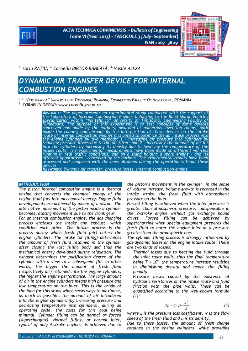
© copyright FACULTY of ENGINEERING ‐ HUNEDOARA, ROMANIA 59
1. Sorin RAŢIU, 2. Corneliu BIRTOK-BĂNEASĂ, 3. Vasile ALEXA
DYNAMIC AIR TRANSFER DEVICE FOR INTERNAL COMBUSTION ENGINES
1, 3. “POLITEHNICA” UNIVERSITY OF TIMISOARA, ROMANIA, ENGINEERING FACULTY OF HUNEDOARA, ROMANIA 2. CORNELIU GROUP: www.corneliugroup.ro
ABSTRACT: The paper presents an experimental study conducted with the support of the Laboratory of Internal Combustion Engines belonging to the Road Motor Vehicles specialization within “Politehnica” University of Timisoara, Engineering Faculty of Hunedoara. The purpose of this experiment is to test concepts of some devices conceived and made by the authors, awarded at numerous invention rooms, both inside the country and abroad. By the interposition of these devices on the intake route of internal combustion engines it is aimed to optimize the air intake process into the engine cylinders by two methods: 1 - increasing air pressure into cylinders by reducing pressure losses due to the air filter, and 2 - increasing the amount of air let into the cylinders by increasing its density due to lowering the temperature of the intake route. The experimental measurements have been made on different vehicles running in real traffic conditions, and on a stand holding a spark engine - and its afferent apparatuses – conceived by the authors. The experimental results have been processed and compared with the ones obtained during the operation without these devices. KEYWORDS: Dynamic air transfer, pressure losses, internal combustion engine
INTRODUCTION The piston internal combustion engine is a thermal engine that converts the chemical energy of the engine fluid fuel into mechanical energy. Engine fluid developments are achieved by means of a piston. The alternative movement of the piston inside a cylinder becomes rotating movement due to the crank gear. For an internal combustion engine, the gas changing process encloses the intake and exhaust, which condition each other. The intake process is the process during which fresh fluid (air) enters the engine cylinders. The intake (or filling) determines the amount of fresh fluid retained in the cylinder after closing the last filling body and thus the mechanical energy developed during relaxation. The exhaust determines the purification degree of the cylinder with a view to a subsequent fill. In other words, the bigger the amount of fresh fluid (respectively air) retained into the engine cylinders, the higher the engine performance. The large amount of air in the engine cylinders means high pressure and low temperature on the inlet. This is the origin of the idea for this study which seeks ways to maximize, as much as possible, the amount of air introduced into the engine cylinders (by increasing pressure and decreasing temperature into cylinders), during an operating cycle, the costs for this goal being minimal. Cylinder filling can be normal or forced (supercharging). Normal filling, or normal inlet, typical of only 4-stroke engines, is achieved due to
the piston’s movement in the cylinder, in the sense of volume increase. Volume growth is recorded in the intake stroke, the fresh fluid with atmospheric pressure on the inlet. Forced filling is achieved when the inlet pressure is greater than atmospheric pressure, indispensable in the 2-stroke engine without gas exchange bound drives. Forced filling can be achieved by supercharging when special equipment prepares the fresh fluid to enter the engine inlet at a pressure greater than the atmospheric one. The cylinder filling process is strongly influenced by gas-dynamic losses on the engine intake route. There are two kinds of losses: � Thermal losses due to heating the fluid through
the inlet route walls, thus the final temperature being T + ΔT, the temperature increase resulting in diminishing density and hence the filling penalty.
� Pressure losses caused by the existence of hydraulic resistances on the intake route and fluid friction with the pipe walls. These can be quantified according to the well-known formula (1):
2wp2
⋅⋅= ρξΔ (1)
where ξ is the pressure loss coefficient, w is the flow speed of the fresh fluid and ρ is its density. Due to these losses, the amount of fresh charge retained in the engine cylinders, while providing
ACTA TECHNICA CORVINIENSIS – Bulletin of Engineering
2013. Fascicule 3 [July–September] 60
information on the filling conditions, cannot serve as a comparison standard for different engines, but only for the same engine (the size of the losses mentioned above differs from one engine to another). This is why we introduce the notion of filling degree, or filling coefficient, or filling efficiency as a criterion for assessing filling perfection [1]:
0v C
C=η (2)
where C is the amount of fresh fluid actually retained in the cylinder, and C0 is the amount of fresh fluid that could be retained in the cylinder, under the state conditions of the engine inlet, i.e. without taking into account the losses mentioned above. Proper filtering of the air that enters the internal combustion engine cylinder is essential to extend its operation. Preventing the intake of various impurities along with atmosphere air significantly reduces the wear and tear of engine parts in relative movement. Unfortunately, besides the function of filtering air drawn from the atmosphere, the air filter – as a distinct part in engine composition - is a significant gas-dynamic resistance interposed on the suction route. If it is not cleaned regularly and the vehicle is driven frequently in dusty areas, the suction pressure pa is reduced consistently and the filling efficiency ηv suffers penalties [1]. DYNAMIC AIR TRANSFER DEVICE (DATD) [2,5] During operation of internal combustion engines fitted on motor vehicles in summer, there can be noted two shortcomings of the air filters, leading to their poor performance: � insufficient air suction effect due to their
installation in the engine compartment, area where the airflow is turbulent, the airflow around the filter not being laminar but turbulent, and the volumetric efficiency suffering penalties;
� increase in the absorbed air temperature due to their installation in the engine compartment, area which is subject to thermal radiation (of the cooling radiator and exhaust manifold). The overheating of the fresh fluid increases engine temperature, the appearance of detonation combustion and engine power reduction.
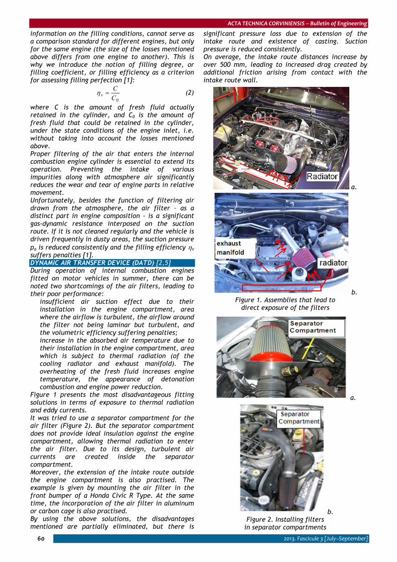
Figure 1 presents the most disadvantageous fitting solutions in terms of exposure to thermal radiation and eddy currents. It was tried to use a separator compartment for the air filter (Figure 2). But the separator compartment does not provide ideal insulation against the engine compartment, allowing thermal radiation to enter the air filter. Due to its design, turbulent air currents are created inside the separator compartment. Moreover, the extension of the intake route outside the engine compartment is also practised. The example is given by mounting the air filter in the front bumper of a Honda Civic R Type. At the same time, the incorporation of the air filter in aluminum or carbon cage is also practised. By using the above solutions, the disadvantages mentioned are partially eliminated, but there is
significant pressure loss due to extension of the intake route and existence of casting. Suction pressure is reduced consistently. On average, the intake route distances increase by over 500 mm, leading to increased drag created by additional friction arising from contact with the intake route wall.
a.
b. Figure 1. Assemblies that lead to
direct exposure of the filters
a.
b. Figure 2. Installing filters
in separator compartments
ACTA TECHNICA CORVINIENSIS – Bulletin of Engineering
2013. Fascicule 3 [July–September] 61
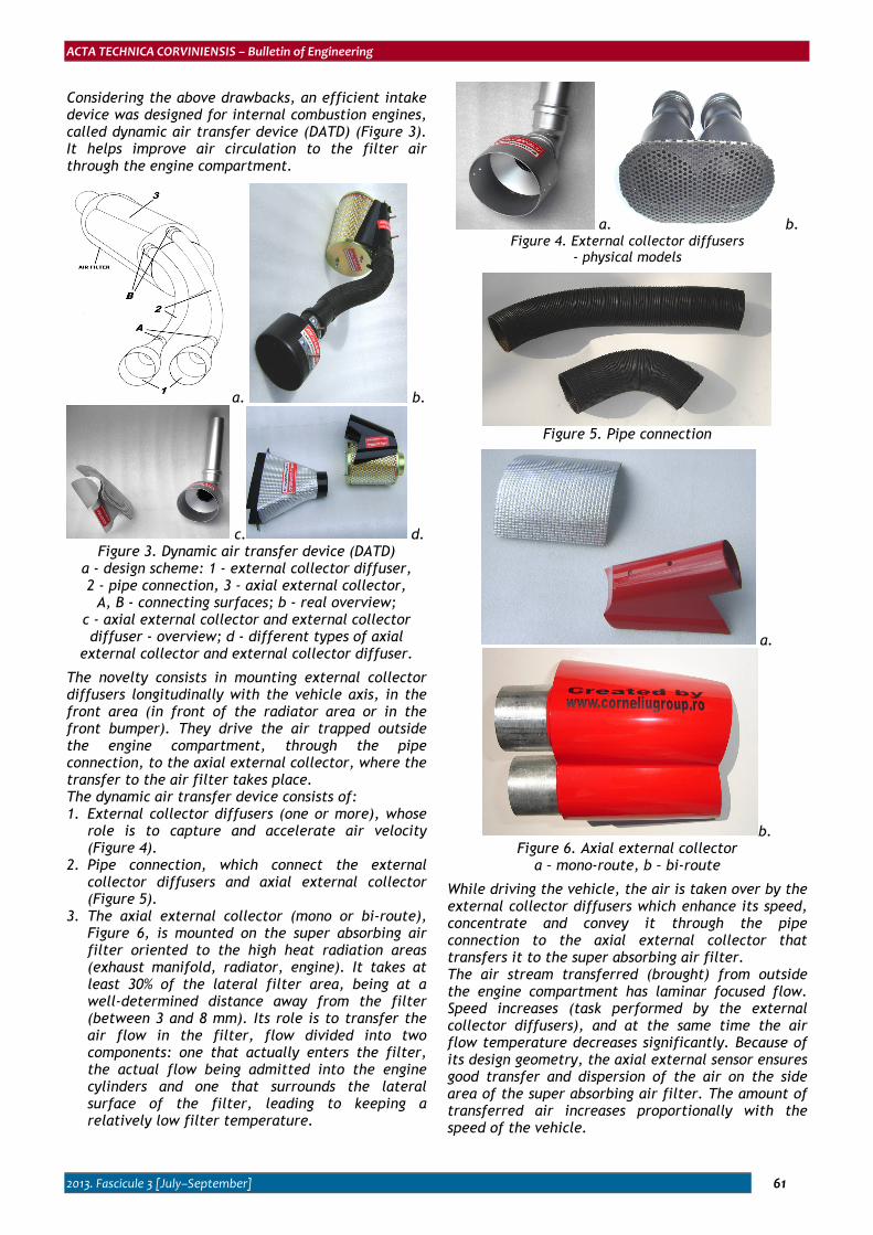
Considering the above drawbacks, an efficient intake device was designed for internal combustion engines, called dynamic air transfer device (DATD) (Figure 3). It helps improve air circulation to the filter air through the engine compartment.
a. b.
c. d. Figure 3. Dynamic air transfer device (DATD)
a - design scheme: 1 - external collector diffuser, 2 - pipe connection, 3 - axial external collector,
A, B - connecting surfaces; b - real overview; c - axial external collector and external collector diffuser - overview; d - different types of axial
external collector and external collector diffuser.
The novelty consists in mounting external collector diffusers longitudinally with the vehicle axis, in the front area (in front of the radiator area or in the front bumper). They drive the air trapped outside the engine compartment, through the pipe connection, to the axial external collector, where the transfer to the air filter takes place. The dynamic air transfer device consists of: 1. External collector diffusers (one or more), whose
role is to capture and accelerate air velocity (Figure 4).
2. Pipe connection, which connect the external collector diffusers and axial external collector (Figure 5).
3. The axial external collector (mono or bi-route), Figure 6, is mounted on the super absorbing air filter oriented to the high heat radiation areas (exhaust manifold, radiator, engine). It takes at least 30% of the lateral filter area, being at a well-determined distance away from the filter (between 3 and 8 mm). Its role is to transfer the air flow in the filter, flow divided into two components: one that actually enters the filter, the actual flow being admitted into the engine cylinders and one that surrounds the lateral surface of the filter, leading to keeping a relatively low filter temperature.
a. b. Figure 4. External collector diffusers
- physical models
Figure 5. Pipe connection
a.
b. Figure 6. Axial external collector
a – mono-route, b – bi-route
While driving the vehicle, the air is taken over by the external collector diffusers which enhance its speed, concentrate and convey it through the pipe connection to the axial external collector that transfers it to the super absorbing air filter. The air stream transferred (brought) from outside the engine compartment has laminar focused flow. Speed increases (task performed by the external collector diffusers), and at the same time the air flow temperature decreases significantly. Because of its design geometry, the axial external sensor ensures good transfer and dispersion of the air on the side area of the super absorbing air filter. The amount of transferred air increases proportionally with the speed of the vehicle.
ACTA TECHNICA CORVINIENSIS – Bulletin of Engineering
2013. Fascicule 3 [July–September] 62
a.
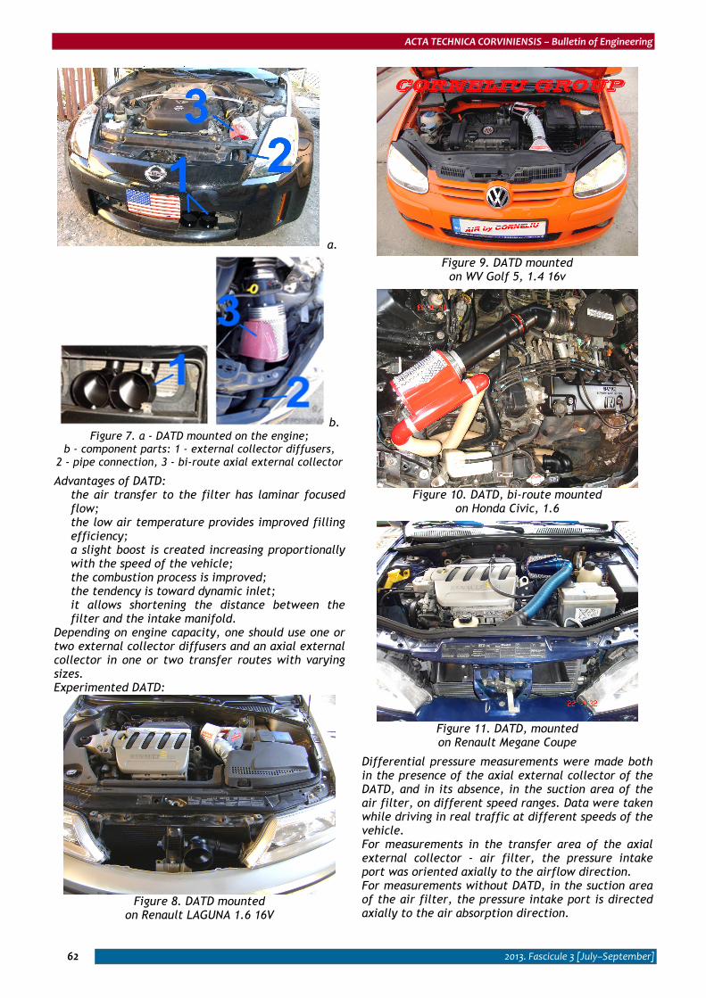
b. Figure 7. a - DATD mounted on the engine;
b - component parts: 1 - external collector diffusers, 2 - pipe connection, 3 - bi-route axial external collector
Advantages of DATD: � the air transfer to the filter has laminar focused
flow; � the low air temperature provides improved filling
efficiency; � a slight boost is created increasing proportionally
with the speed of the vehicle; � the combustion process is improved; � the tendency is toward dynamic inlet; � it allows shortening the distance between the
filter and the intake manifold. Depending on engine capacity, one should use one or two external collector diffusers and an axial external collector in one or two transfer routes with varying sizes. Experimented DATD:
Figure 8. DATD mounted
on Renault LAGUNA 1.6 16V
Figure 9. DATD mounted
on WV Golf 5, 1.4 16v
Figure 10. DATD, bi-route mounted
on Honda Civic, 1.6
Figure 11. DATD, mounted on Renault Megane Coupe
Differential pressure measurements were made both in the presence of the axial external collector of the DATD, and in its absence, in the suction area of the air filter, on different speed ranges. Data were taken while driving in real traffic at different speeds of the vehicle. For measurements in the transfer area of the axial external collector - air filter, the pressure intake port was oriented axially to the airflow direction. For measurements without DATD, in the suction area of the air filter, the pressure intake port is directed axially to the air absorption direction.
ACTA TECHNICA CORVINIENSIS – Bulletin of Engineering
2013. Fascicule 3 [July–September] 63
3
23
43
63
83
103
123
143
163
25 30 35 40 45 50 55 60 65vehicle speed [km/h]
pres
ure
[Pa]
w ith DATD
w ithout DATD
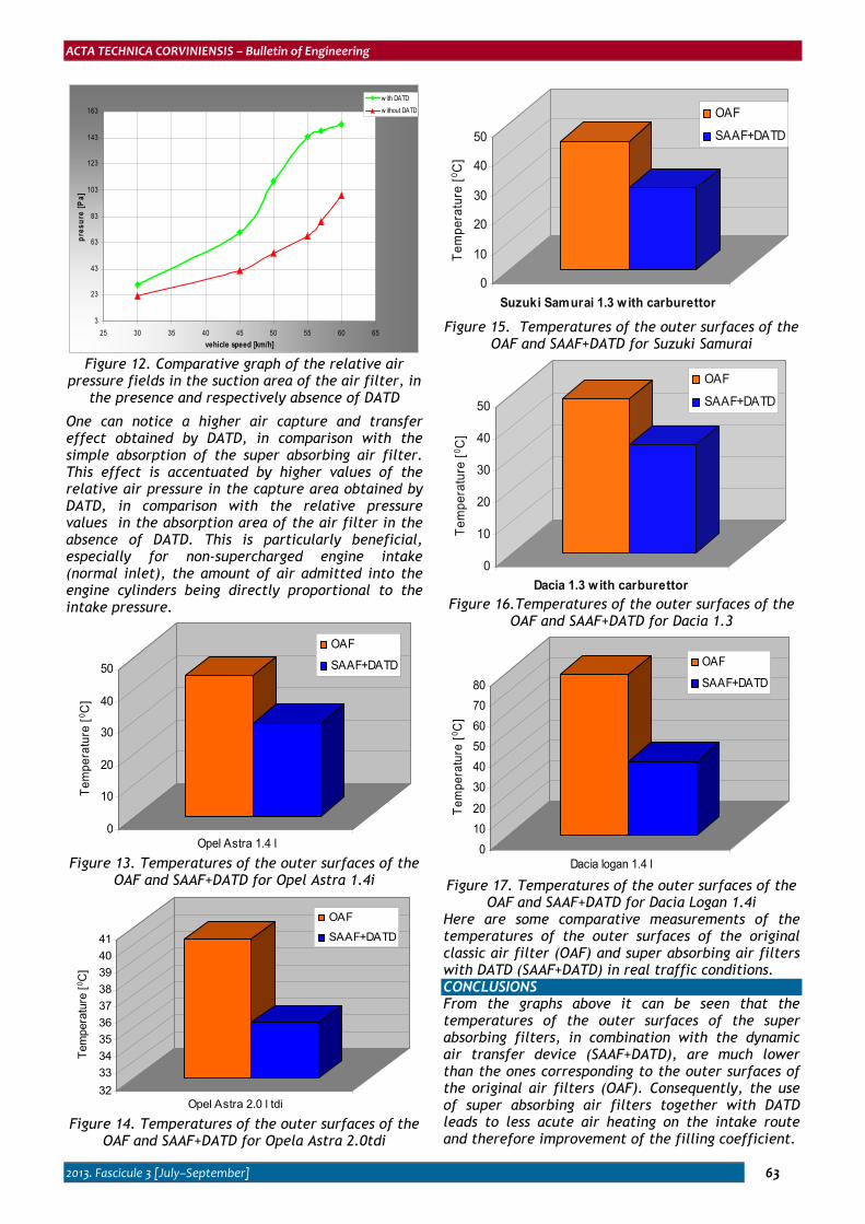
Figure 12. Comparative graph of the relative air
pressure fields in the suction area of the air filter, in the presence and respectively absence of DATD
One can notice a higher air capture and transfer effect obtained by DATD, in comparison with the simple absorption of the super absorbing air filter. This effect is accentuated by higher values of the relative air pressure in the capture area obtained by DATD, in comparison with the relative pressure values in the absorption area of the air filter in the absence of DATD. This is particularly beneficial, especially for non-supercharged engine intake (normal inlet), the amount of air admitted into the engine cylinders being directly proportional to the intake pressure.
0
10
20
30
40
50
Tem
pera
ture
[ 0 C]
Opel Astra 1.4 l
OAF
SAAF+DATD
Figure 13. Temperatures of the outer surfaces of the
OAF and SAAF+DATD for Opel Astra 1.4i
32333435363738394041
Tem
pera
ture
[ 0 C]
Opel Astra 2.0 l tdi
OAF
SAAF+DATD
Figure 14. Temperatures of the outer surfaces of the
OAF and SAAF+DATD for Opela Astra 2.0tdi
0
10
20
30
40
50
Tem
pera
ture
[ 0 C]
Suzuki samurai 1.3 carburatorSuzuki Samurai 1.3 w ith carburettor
OAF
SAAF+DATD
Figure 15. Temperatures of the outer surfaces of the
OAF and SAAF+DATD for Suzuki Samurai
0
10
20
30
40
50
Tem
pera
ture
[ 0 C]
Dacia 1.3 carburatorDacia 1.3 w ith carburettor
OAF
SAAF+DATD
Figure 16.Temperatures of the outer surfaces of the
OAF and SAAF+DATD for Dacia 1.3
01020
304050607080
Tem
pera
ture
[ 0 C]
Dacia logan 1.4 l
OAF
SAAF+DATD
Figure 17. Temperatures of the outer surfaces of the
OAF and SAAF+DATD for Dacia Logan 1.4i Here are some comparative measurements of the temperatures of the outer surfaces of the original classic air filter (OAF) and super absorbing air filters with DATD (SAAF+DATD) in real traffic conditions. CONCLUSIONS From the graphs above it can be seen that the temperatures of the outer surfaces of the super absorbing filters, in combination with the dynamic air transfer device (SAAF+DATD), are much lower than the ones corresponding to the outer surfaces of the original air filters (OAF). Consequently, the use of super absorbing air filters together with DATD leads to less acute air heating on the intake route and therefore improvement of the filling coefficient.
ACTA TECHNICA CORVINIENSIS – Bulletin of Engineering
2013. Fascicule 3 [July–September] 64
REFERENCES [1.] Raţiu S, Mihon L (2008) Internal Combustion
Engines for Motor Vehicles - Processes and Features, MIRTON Publishing House, Timişoara, pp. 44-47;
[2.] Birtok-Băneasă C, Raţiu S (2011) Air Intake of Internal Combustion Engines – Super Absorbing Filters - Dynamic Transfer Devices, POLITEHNICA Publishing House, Timişoara, pp. 15-90;
[3.] Raţiu S (2009) Internal Combustion Engines for Motor Vehicles - Processes and Features – Laboratory Experiments, MIRTON Publishing House, Timişoara, pp. 40-42;
[4.] Raţiu S, Birtok-Băneasă C, Alic C, Mihon L (2009) New concepts in modeling air filters for internal combustion engines, 20th International DAAAM SYMPOSIUM "Intelligent Manufacturing & Automation: Theory, Practice & Education", Vienna, Austria, ISSN 1726-9679
[5.] www.corneliugroup.ro
ACTA TECHNICA CORVINIENSIS – Bulletin of Engineering
ISSN: 2067-3809 [CD-Rom, online]
copyright © UNIVERSITY POLITEHNICA TIMISOARA, FACULTY OF ENGINEERING HUNEDOARA,
5, REVOLUTIEI, 331128, HUNEDOARA, ROMANIA http://acta.fih.upt.ro