Embed Size (px)
Citation preview
AD
CONTRACTOR REPORT ARCCB-CR-99001
DYNAMIC ANALYSIS OF A 155-MM CANNON BREECH
G. PETER OHARA
ELMHURST RESEARCH TROY, NY 12181
FEBRUARY 1999
US ARMY ARMAMENT RESEARCH, DEVELOPMENT AND ENGINEERING CENTER
CLOSE COMBAT ARMAMENTS CENTER BENET LABORATORIES
WATERVLIET, N.Y. 12189-4050
APPROVED FOR PUBLIC RELEASE; DISTRIBUTION UNLIMITED
mm QUALTEY wsrmmk &

DISCLAIMER
The findings in this report are not to be construed as an official Department of the
Army position unless so designated by other authorized documents.
The use of trade name(s) and/or manufacturer(s) does not constitute an official
endorsement or approval.
DESTRUCTION NOTICE
For classified documents, follow the procedures in DoD 5200.22-M, Industrial
Security Manual, Section 11-19, or DoD 5200.1-R, Information Security Program
Regulation, Chapter DC.
For unclassified, limited documents, destroy by any method that will prevent
disclosure of contents or reconstruction of the document.
For unclassified, unlimited documents, destroy when the report is no longer
needed. Do not return it to the originator.
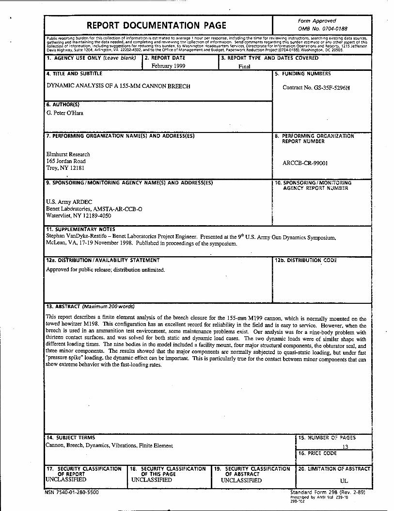
REPORT DOCUMENTATION PAGE Form Approved
OMB No. 0704-0188
Public reporting burden for this collection of information is estimated to average 1 hour per response, including the time for reviewing instructions, searching existing data sources, gathering and maintaining the data needed, and completing and reviewing the collection of information. Send comments regarding this burden estimate or any other aspect of this collection of information, including suggestions for reducing this burden, to Washington Headquarters Services, Directorate for Information Operations and Reports, 1215 Jefferson Davis Highway, Suite 1204, Arlington, VA 22202-4302, and to the Office of Management and Budget, Paperwork Reduction Project (0704-0188), Washington, DC 20503.
1. AGENCY USE ONLY (Leave blank) 2. REPORT DATE
February 1999
3. REPORT TYPE AND DATES COVERED
Final 4. TITLE AND SUBTITLE
DYNAMIC ANALYSIS OF A 155-MM CANNON BREECH
6. AUTHOR(S)
G. Peter O'Hara
5. FUNDING NUMBERS
Contract No. GS-35F-5296H
7. PERFORMING ORGANIZATION NAME(S) AND ADDRESS(ES)
Elmhurst Research 165 Jordan Road Troy, NY 12181
8. PERFORMING ORGANIZATION REPORT NUMBER
ARCCB-CR-99001
9. SPONSORING /MONITORING AGENCY NAME(S) AND ADDRESS(ES)
U.S. Army ARDEC Benet Laboratories, AMSTA-AR-CCB-0 Watervliet, NY 12189-4050
10. SPONSORING/MO?siTORiNG AGENCY REPORT SäUSViSER
11. SUPPLEMENTARY NOTES Stephan VanDyke-Restifo - Benet Laboratories Project Engineer. Presented at the 9th U.S. Army Gun Dynamics Symposium, McLean, VA, 17-19 November 1998. Published in proceedings of the symposium.
12a. DISTRIBUTION/AVAILABILITY STATEMENT
Approved for public release; distribution unlimited.
12b. DISTRIBUTION CODE
13. ABSTRACT (Maximum 200 words)
This report describes a finite element analysis of the breech closure for the 155-mm Ml99 cannon, which is normally mounted on the towed howitzer M198. This configuration has an excellent record for reliability in the field and is easy to service. However, when the breech is used in an ammunition test environment, some maintenance problems exist. Our analysis was for a nine-body problem with thirteen contact surfaces, and was solved for both static and dynamic load cases. The two dynamic loads were of similar shape with different loading times. The nine bodies in the model included a facility mount, four major structural components, the obturator seal, and three minor components. The results showed that the major components are normally subjected to quasi-static loading, but under fast "pressure spike" loading, the dynamic effect can be important. This is particularly true for the contact between minor components that can show extreme behavior with the fast-loading rates.
I
14. SUBJECT TERMS
Cannon, Breech, Dynamics, Vibrations, Finite Element 15. DUMBER Or PAGES
13 16. PRICE CODE
20. LIMITATION OF ABSTRACT
UL
17. SECURITY CLASSIFICATION OF REPORT
UNCLASSIFIED
18. SECURITY CLASSIFICATION OF THIS PAGE
UNCLASSIFIED
19. SECURITY CLASSIFICATION OF ABSTRACT
UNCLASSIFIED
NSN 7540-01-280-5500 Standard Form 298 (Rev. 2-89) Prescribed by ANSI Std. Z39-18 298-102

TABLE OF CONTENTS Page
ACKNOWLEDGEMENTS ii
INTRODUCTION 1
DESCRIPTION OF COMPONENT MODELS 1
CONTACT SURFACES 4
LOADING 4
RESULTS 5
DISCUSSION 9
CONCLUSION 10
REFERENCES 11
TABLES
1. Mises' Stress Comparison for Three Loading Rates and Four Major Components 7
LIST OF ILLUSTRATIONS
1. Cross section of the full system model 2
2. Detail of the housing-to-spindle connection 3
3. Pressure-time curve for the M203 charge 5
4. Typical Mises' stress contour at a pressure of 310 MPa 6
5. Lug/front contact stress for normal M203 charge 8
6. Lug/front contact for the pressure spike 9

ACKNOWLEDGEMENTS
The author wishes to acknowledge the support of Mr. Richard Hasenbein and Mr. Stephen VanDyke-Restifo of Benet Laboratories for support in this work. The author also wishes to thank Mr. George Pflegl for his advice and council.
INTRODUCTION
The 155-mm Ml98 towed howitzer has been in service with the U.S. Armed Services since 1978 and has proven to be a reliable weapon with few problems in service. This system uses the 155-mm Ml99 cannon, which was designed at Benet Laboratories, with an Eastman style interrupted screw block breech and a DeBange obturator seal. Interrupted screw threads used for the breechblock-to-breech ring connection are also used for the breech ring-to-barrel connection and in the breech ring-to-recoil mount joint. A similar interrupted lug joint is used to assemble the firing mechanism housing to the obturator spindle, as a means of allowing easy assembly in the field. While the normal maintenance record of gun is excellent, there have been some problems with the breech when it is used on ballistic guns for ammunition testing. In this environment the breech is subjected to prototype propellant systems and other conditions that may produce "ragged" pressure-time histories. These histories are characterized by large pressure spikes, which apparently do not affect the primary structure but do produce failure in the small components such as the firing mechanism housing. The case in point includes the lugs on the obturator spindle that retain the housing on the spindle. These lugs have been noted to produce bearing failures, thus making the components difficult to disassemble. Our analysis was intended to explore this effect and to demonstrate the value of the analysis of a full cannon breech.
This report describes the static and dynamic finite element analysis of the breech closure for the Ml99 cannon. The work compares three different time frames: a static case and dynamic cases using a normal pressure time curve and a very fast pressure spike. Our analysis was conducted at a medium level of detail with the components described by eight-node axisymmetric elements and the various contact surfaces modeled using an appropriate interface formulation. The three major threaded connections were modeled with the individual threads smeared to an equivalent orthotropic continuum and contact modeled using the appropriate kinematics conditions. Other contact surfaces were modeled using either a small sliding or large sliding formulation. All of the necessary analysis tools were available in the ABAQUS standard finite element code (refs 1,2).
DESCRIPTION OF COMPONENT MODELS
The initial objective of this study was to produce individual models of all necessary structural components of the cannon breech and link them to produce the overall system model. This was done with eight-node axisymmetric elements (CAX8), and is a reasonable assumption for these components. The breech ring and block both have nonsymmetric features, but they can be ignored in favor of the more general solution goals. The block carrier is a totally nonsymmetric structure but this has been ignored because it does not play a structural role during firing. The firing mechanism is another nonsymmetric structure, but this level of detail is not appropriate to our analysis. However, it was necessary to include the mass of the firing mechanism in the model of the firing housing.
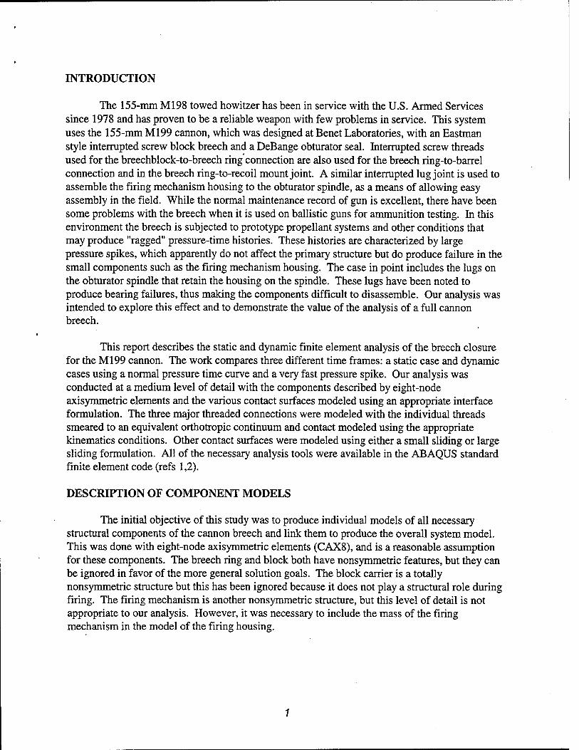
A cross-sectional drawing of the breech is shown in Figure 1 with the major components labeled and a brief description given below. The diagonal lines show the kinematic direction of the thread bearing surfaces.
Barrel
Spindle Housing
Figure 1. Cross section of the full system model.
1. Barrel assembly: The model includes about 0.6 meter of the breech end of the barrel, including the obturator pad seat, tube-to-ring threads, and two pilot surfaces. A small portion at the forward end uses an increased mass to replace the unmodeled portion of the barrel assembly. To further enhance the model, the nodes at the muzzle end are constrained to a constant axial displacement.
2. Breech ring: This model is an axisymmetric approximation of the breech ring with tube-to-ring threads, block-to-ring threads, mount-to-ring threads, the two pilot surfaces for the tube, and a pilot surface for the mount. The outer surface contour is a rather unusual shape that resulted from a complicated development history and a need for a specific breech weight.
3. Breechblock: This is a full model of the block, including the block-to-ring threads on the outer diameter and the block-to-disk contact surface on the muzzle face.
4. Obturator spindle: This is a model of the spindle, including the housing-to-spindle contact surfaces, the spindle-to-pad contact surface, and the pad-to-disk contact. The small extension at the breech end retains the primer and is normally not on the centerline of the gun but has been moved in this model. The material stiffness for the lugs is reduced, thus illustrating the fact that they are interrupted in the actual component setup.
5. Obturator pad and rings: The pad and rings are included as one body because sliding contact between them can be ignored. The fact that the pad is an elastomer and the rings are steel is modeled. Also since the rings are split rings, the steel is given a very low hoop stiffness.
6. Disk: This is a simple washer located between the obturator pad and the breechblock. It has a small sliding surface on each axial face.
7. Mount: The mount is modeled as a short cylinder with the ring-to-mount threads on the inside along with a mount-to-ring pilot surface. The outer volume uses the increased mass property to replace the mass of a facility mount.
8. Cam plate: This is a nonstructural plate that is bolted to the breech face of the block and is included because of its inertial load on the block. The bolts are modeled using three simple springs that are preloaded by using a small interference of the contact surface with the block.
9. Housing: The housing model includes the mass of the firing mechanism, a contact surface at the muzzle end with the obturator spindle, and the housing-to-spindle lug connection.
The dimensions for these components were taken directly from Benet Laboratories drawings for the individual components, and nominal dimensions were used for all of the gaps between contact surfaces.
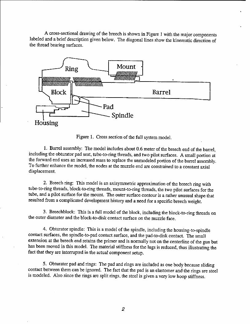
Figure 2 illustrates a detail of the housing and spindle, showing how the housing is retained between the spindle body at the front (muzzle end) and a set of interrupted lugs at the breech end. With this system, the assembly requires insertion of the spindle into the housing until it bottoms on the front interface; then a simple one-quarter turn locks in both the spindle and housing using a spring pin. A small gap or play between the two interfaces allows easy assembly, which is a minimum of 0.000254 meter (0.010 inch) on the drawings. This fact will play a role in the conclusions of our analysis.
Front Interface
Housing
Spindle
Lug Interface
Figure 2. Detail of the housing-to-spindle connection.
CONTACT SURFACES
Three types of interfaces make up the overall model: small sliding contact, large sliding contact, and the complex thread interaction model. The small sliding surface formulation in ABAQUS (INTER3A) is used for the three pilot surfaces that close a radial gap, and the five contact surfaces that act in the axial direction. All are initially closed. The Slide Line (ISL22A) formulation for large sliding contact is used for obturator pad/spindle interaction and the obturator pad/barrel interaction. The pad is an elastomer subjected to very high loads and deformations. These deformations allow the pad/rings to have substantial motions relative to the barrel, breechblock, and spindle.
The three threaded connections are modeled using a combination of material replacement for threads and a set of oriented one-dimensional gap elements to provide the proper kinematics of the thread contact surfaces. This method has been used for several years (ref 3) and was originally suggested by Bretl (ref 4). The first step is to calculate an equivalent orthotropic material with the same global stiffness as the full height of the threads. This material occupies the space between the thread root and the pitch cylinder on each side of the connection. A detailed analysis of a single thread tooth was used to establish these properties using methods similar to work done in studies of thread performance (refs 5-7). The individual threads are then smeared into two rows of elements, with one row attached to each of the adjoining components. These rows meet at the pitch cylinder of the threads in a set of independent node pairs. The pairs are linked with one-dimensional gap elements (GAPUNI), in a coordinate system that enables sliding parallel to the thread contact surface direction. The two connected points are at the same point in space, and the direction vector for gap is defined normal to the thread contact surface. These two techniques model the stiffness and kinematics of the thread contact without resorting to defining individual thread teeth.
LOADING
The primary loads are the pressure load in the chamber of the gun and the inertial loads from recoil. The pressure load covers the muzzle surface of the spindle, the bore surface forward of the obturator pad, and the inner diameter of the flame hole in the spindle. The pressure load is also reflected in a small concentrated load on the housing to simulate the axial load of the primer on the firing mechanism. Inertial loads are applied as a constant body force in the static solution and by using the free recoil condition for the dynamic solutions.
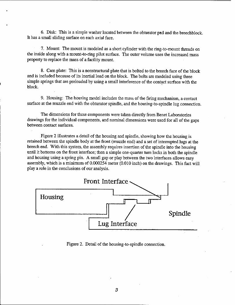
The three loads used reflect the behavior of an M203 charge in an Ml99 cannon. The basic pressure-time shown in Figure 3 was obtained from a XNOVAKTC interior ballistics solution (refs 8-10) for this charge and was entered into ABAQUS as a table of 148 x-y pairs. In this interior ballistics solution, the projectile motion started at 0.0048 second with the peak pressure of 310 MPa at 0.0099 second. Shot exit was at 0.020 second and the data table was cut off at 0.025 second. The peak pressure was used for the static solution along with a body force calculated from simple rigid body mechanics. The full pressure-time curve was used for the first dynamic solution to model the normal behavior of the breech. For the pressure spike case, the
time of the M203 charge was simply divided by 10 to produce a spike of the same pressure and shape, but with a duration of 0.0025 second.
350 (Ö
a 300
250 2 CO
200 u G«
150 ja a 100 Ä O
50
T—i—i—i—I—i—i—r—r T—r I ' ' ' ' I
j u J—I—i—i—i—i—I—i i i i I i ■■»>»■■■"
0 0.005 0.01 0.015 Time
0.02 0.025
Figure 3. Pressure-time curve for the M203 charge.
RESULTS
The overall system model was debugged as a static problem and a test of the various contact surfaces. As always in this sort of problem, most of the modifications were in favor of a more realistic model, which generally makes the solution faster and more reliable. As a case in point, the disk was originally included as an extension on the block model, however it would not converge or would converge to an incorrect deformed shape. The disk is a bearing that operates to release the shear deformation between the block and the pad. Without fully modeling this function, the "hourglass" mode of the elements becomes a dominant behavior and produces an incorrect deformed shape. Inclusion of the disk as a separate component, with two contact surfaces, solved this problem.
The stress contour plot in Figure 4 is typical of the general Mises' stresses at the maximum pressure. Note the high stresses near the bore of the chamber, in the breechblock, and in the pad fillet of the spindle. Also note that there are no contours in the obturator pad, which is in a state of hydrostatic compression. There is also a stress concentration in the ring at the thread relief for the block end threads. This rather mild stress concentration links with the stress concentration of the threads to produce the actual fatigue failure point in the ring.
Figure 4. Typical Mises' stress contour at a pressure of 310 MPa.
After the static model was completed, the dynamic solutions proceeded easily and the major problem became selecting and displaying the important results. It was decided early to select four points for stress comparisons of the various solutions. These points were all at high stress points of the major components. The first was at the bore of the barrel (3111-1), then one in the thread relief of the ring (6152-1), another in the block near the central hole (1166-7), and the last at the pad fillet of the spindle (8201-1). Mises' equivalent stresses for these four points and the three loading conditions are shown in Table 1. Note that there is no difference between the static solution and the standard M203 charge solution. The pressure spike solution produced modest stress increases of as little as 1 percent for the bore of the tube, to a high of 48 percent for the spindle. All of these were recorded at the time of maximum pressure in the chamber.

Table 1. Mises' Stress Comparison for Three Loading Rates and Four Major Components
Component Static (MPa)
M203 Charge (MPa)
Pressure Spike (MPa)
Tube (3111-1) 807.8 808.0 817.0 Ring (6152-1) 384.8 381.0 530.6 Block (1166-7) 999.8 993.6 1301.4 Spindle (8208-1) 883.2 878.0 1319.2
The spindle movement is a critical part of the operation of the obturator pad seal in this style of cannon. This is a Bridgman unsupported area seal, and uses the spindle to increase the pressure on the pad and force it against the pad seat of the barrel. The elastomer pad is compressed by the full axial pressure load on the spindle, and is restrained on the pad seat and breechblock . The seat is tapered so that as the pad moves rearward, it must expand to meet the new diameter of the tube. At the same time, the tube is expanding from the pressure load of the pad and the block is deflecting backward from the axial load in it. All of these combine to produce the spindle movement of 2.2-mm relative to either the block or the tube. This movement opens a large space between the spindle and the tube that would allow the elastomer pad to extrude out if the split rings were not in place. The front split ring prevents this extrusion along with its mating split ring in the smaller space between the tube and the disk.
The first dynamic solution used the pressure-time data for the M203 charge and some of the basic structural information reported in Table 1. This was a free recoil case that yielded a rigid body displacement of 0.0075 meter at the time of peak pressure and 0.088 meter at shot exit. The corresponding recoil velocities were 3.98 and 9.92 meter/second. These numbers tended to reinforce the quality of the solution. However, a major goal was to study the contact conditions on the lugs and the front contact surfaces of the housing. This was done by plotting the contact stress against time, as shown in Figure 5. The plot shows a rather complex behavior, which was influenced by local natural frequencies. The general stress level was low with a maximum of about 55 MPa on the lugs. The front contact surface was only activated twice between 0.004 and 0.007 second. Certainly one would not predict any sort of failure from this response.
i—i—i—i—I—i—i—i—r
CO
CO en
b
wMtätüMri 1 L
0 0,005 0.01 0.015 0.02 0.025 Time (s)
Figure 5. Lug/front contact stress for normal M203 charge.
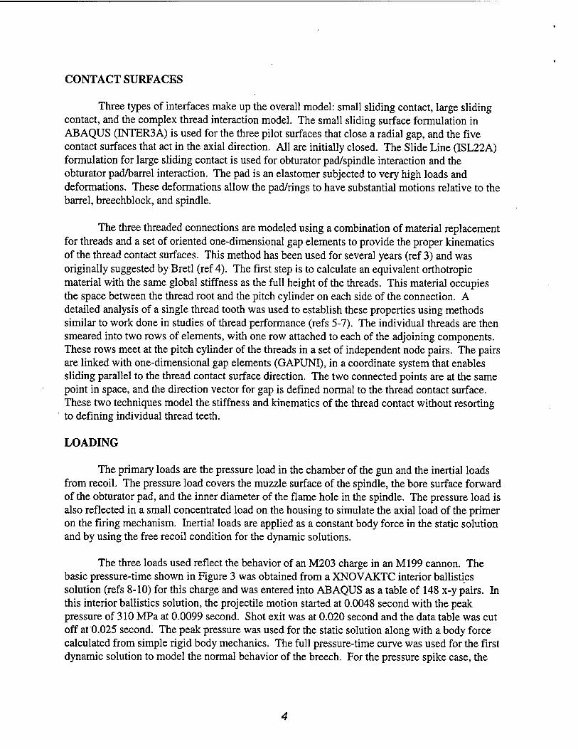
The last solution, for the pressure spike, was generally similar to the other two cases with some increase in general stresses as noted in Table 1. This small increase was not the case for the lug contact stress in the spindle and housing. Here a plot of contact stresses versus time for the lugs and the front contact surface revealed a very different picture of the stress levels, hence demonstrating a clear behavior. The maximum contact stress on the lugs became 1125 MPa, and the front contact surface was very active. At this high loading rate, the housing bounced across the gap impacting heavily on both surfaces. The maximum stress increased by a factor of 20 with the contact stress approaching the yield strength of the steel. Clearly, one could predict a possible failure for this case.
8

cd
B CO CO
t/1
1200
1000
800
600
400
200
0
: Front
T—i—r T—i—i—i—r—i—r—i—i—i—r-T—r~i—i—r~i—i—r
II
J I I l_
0 0.0005 0.001 0.0015 0.002 0.0025 Time (s)
Figure 6. Lug/front contact for the pressure spike.
DISCUSSION
The three solutions in this report are for quite different time frames and show different data when viewed from different perspectives. When the data are viewed from a general structural viewpoint, some important effects can be demonstrated. For example, static analysis may be a valid assumption for the design of large cannon components when the analysis is for a normal well-behaved charge. If the propellant does not burn smoothly and pressure spikes are generated, some components may be subject to increased stress conditions. This is the case for the spindle fillet, which shows a 48 percent gain in Mises' stress. However, when we look in detail at the spindle/housing interactions, a rather different picture emerges. In the static case, the primer load pushes the housing against the spindle lug at an average of 11.4 MPa and nothing more. Yet when the normal pressure-time curve is introduced, a much more complex behavior is introduced and the contact load varies rapidly at low stresses. Then at very high rate loads, another behavior is demonstrated in which the housing bounces rapidly between the front contact surface and the lug surface, resulting in high contact surfaces and possible failure of the lugs.
It is not enough to solve large, complex finite element models of complicated structures and casually view the results. These models create enormous volumes of information, which must be critically evaluated to find the pertinent information. In this case, the initial request was to seek an explanation for the bearing failure of the spindle lugs. This, in turn, prompted the investigation of the lug contact stresses. The information on variation of general stresses with loading rate is one of the many other areas that could be investigated along with the primary analysis goal. Another point is the necessity of doing more than one analysis. The interesting part of our study was the comparison of three different loading rates, and not the results of any single computer run. It should be pointed out that the results shown in this report are for three runs using the same structural model, the same computer code (ABAQUS), and the same solution tolerance for the dynamic load cases. While the work may continue to make the solutions more efficient, this report provides a consistent set to be used for comparisons.
CONCLUSION
This work tends to validate the very old idea that structural analysis of cannon breeches can be done by quasi-static methods. The burning of propellants is not an explosion, but a deflagration that should result in a rather smooth and (relatively) slow pressure-time curve. However, this is only true for the major structural components and a well-behaved propellant charge. When high-level pressure spikes are involved, the stress picture changes and the changes can be rather dramatic.
10
REFERENCES
1. ABAQUS Theory Manual, Version 5.7, Hibbitt, Karlsson, and Sorensen, Inc., 1080 Main Street, Pawtucket, RI, 1997.
2. ABAQUS User's Manual, Version 5.7, Hibbitt, Karlsson, and Sorensen, Inc., 1080 Main Street, Pawtucket, RI, 1997.
3. O'Hara, G.P., "Analysis of a Large High Pressure Vessel Closure," Proceedings ofASME Pressure Vessels and Piping Conference, Orlando, FL, July 1988; Also ARDEC Technical Report ARCCB-TR-89003, Benet Laboratories, Watervliet, NY, January 1989.
4. Bretl, J.L., "Finite Element Analysis for General Solids and Threaded Connections," Ph.D. Thesis, University of Wisconsin-Madison, 1978.
5. O'Hara, G.P., "Stress Concentrations in Screw Threads," Eighth NASTRAN Users' Colloquium, Goddard Space Flight Center, NASA Conference Publication 2131, October 1979, pp. 65-77; Also (with Appendix) Technical Report ARLCB-TR-80010, Benet Laboratories, Watervliet, NY, April 1980.
6. O'Hara, G.P., "Elastic-Plastic Comparison of Three Thread Forms," Proceedings of the Eighth U.S. Army Symposium on Gun Dynamics, (G. Albert Pflegl, Ed.), ARCCB-SP- 96032, Benet Laboratories, Watervliet, NY, November 1996, pp. 18-1 to 18-10.
7. O'Hara, G.P., "Elastic Comparison of Four Thread Forms," Proceedings ofASME Pressure Vessels and Piping Conference, Orlando FL, PVP Vol. 344, July 1997.
8. Gough, P.S., "The NOVA Code: A User's Manual," Contractor Report IHCR-80-8, Indian Head Naval Ordnance Station, 1980.
9. Gough, P.S., "The XNOVA Code: A User's Manual," Contractor Report N00174-86-M- 4336, PGA 88-2, Indian Head Naval Ordnance Station, December 1988.
10. Gough, P.S., "The XNOVAKTC Code," Final Report, Contract DAAK11-85-D-00002, Task n, PGA-TR-86-1, U.S. Army Ballistic Research Laboratory, Aberdeen Proving Ground, MD, March 1986.
11

TECHNICAL REPORT INTERNAL DISTRIBUTION LIST
NO. OF COPIES
CHIEF, DEVELOPMENT ENGINEERING DIVISION ATTN: AMSTA-AR-CCB-DA 1
-DB 1 -DC 1 -DD 1 -DE 1
CHIEF, ENGINEERING DIVISION ATTN: AMSTA-AR-CCB-E 1
-EA 1 -EB 1 -EC 1
CHIEF, TECHNOLOGY DIVISION ATTN: AMSTA-AR-CCB-T 2
-TA 1 -TB 1 -TC 1
TECHNICAL LIBRARY ATTN: AMSTA-AR-CCB-0 5
TECHNICAL PUBLICATIONS & EDITING SECTION ATTN: AMSTA-AR-CCB-0 3
OPERATIONS DIRECTORATE ATTN: SIOWV-ODP-P 1
DIRECTOR, PROCUREMENT & CONTRACTING DIRECTORATE ATTN: SIOWV-PP 1
DIRECTOR, PRODUCT ASSURANCE & TEST DIRECTORATE ATTN: SIOWV-QA 1
NOTE: PLEASE NOTIFY DIRECTOR, BENET LABORATORIES, ATTN: AMSTA-AR-CCB-0 OF ADDRESS CHANGES.

TECHNICAL REPORT EXTERNAL DISTRIBUTION LIST
DEFENSE TECHNICAL INFO CENTER ATTN: DTIC-OCA (ACQUISITIONS) 8725 JOHN J. KINGMAN ROAD STE 0944 FT. BELVOIR, VA 22060-6218
COMMANDER U.S. ARMY ARDEC ATTN: AMSTA-AR-WEE, BLDG. 3022
AMSTA-AR-AET-O, BLDG. 183 AMSTA-AR-FSA, BLDG. 61 AMSTA-AR-FSX AMSTA-AR-FSA-M, BLDG. 61 SO AMSTA-AR-WEL-TL, BLDG. 59
PICATINNY ARSENAL, NJ 07806-5000
DIRECTOR U.S. ARMY RESEARCH LABORATORY ATTN: AMSRL-DD-T, BLDG. 305 ABERDEEN PROVING GROUND, MD
21005-5066
DIRECTOR U.S. ARMY RESEARCH LABORATORY ATTN: AMSRL-WM-MB (DR. B. BURNS) ABERDEEN PROVING GROUND, MD
21005-5066
NO. OF NO. OF COPIES
COMMANDER
COPIES
2 ROCK ISLAND ARSENAL ATTN: SIORI-SEM-L 1 ROCK ISLAND, IL 61299-5001
COMMANDER U.S. ARMY TANK-AUTMV R&D COMMAND ATTN: AMSTA-DDL (TECH LIBRARY) 1 WARREN, MI 48397-5000
COMMANDER U.S. MILITARY ACADEMY ATTN: DEPT OF CIVIL & MECH ENGR 1 WEST POINT, NY 10966-1792
U.S. ARMY AVIATION AND MISSILE COM REDSTONE SCIENTIFIC INFO CENTER 2 ATTN: AMSAM-RD-OB-R (DOCUMENTS) REDSTONE ARSENAL, AL 35898-5000
COMMANDER U.S. ARMY FOREIGN SCI & TECH CENTER ATTN: DRXST-SD 1 220 7TH STREET, N.E. CHARLOTTESVILLE, VA 22901
COMMANDER U.S. ARMY RESEARCH OFFICE ATTN: TECHNICAL LIBRARIAN P.O. BOX 12211 4300 S. MIAMI BOULEVARD RESEARCH TRIANGLE PARK, NC 27709-2211
NOTE: PLEASE NOTIFY COMMANDER, ARMAMENT RESEARCH, DEVELOPMENT. AND ENGINEERING CENTER, BENET LABORATORIES, CCAC, U.S. ARMY TANK-AUTOMOTIVE AND ARMAMENTS COMMAND,
AMSTA-AR-CCB-O, WATERVLIET, NY 12189-4050 OF ADDRESS CHANGES.