Embed Size (px)
Citation preview

Research ArticleDynamic Characterization of Rubber O-Rings:Squeeze and Size Effects
Farid Al-Bender,1 Federico Colombo,2 Dominiek Reynaerts,1
Rodrigo Villavicencio,2 and Tobias Waumans3
1Division of Production Engineering, Machine Design and Automation, KU Leuven, Leuven, Belgium2Department of Mechanical and Aerospace Engineering, Politecnico di Torino, Torino, Italy3Leuven Air Bearings, KU Leuven, Leuven, Belgium
Correspondence should be addressed to Federico Colombo; [email protected]
Received 2 May 2017; Accepted 13 June 2017; Published 12 July 2017
Academic Editor: Michel Fillon
Copyright © 2017 Farid Al-Bender et al.This is an open access article distributed under theCreativeCommonsAttribution License,which permits unrestricted use, distribution, and reproduction in any medium, provided the original work is properly cited.
This paper concerns the dynamic characterization of rubber O-rings used to introduce damping in high speed gas bearing systems.O-shaped rubber rings composed of high temperature rubber compounds are characterized in terms of stiffness and dampingcoefficients in the frequency range 100–800Hz. Simple formulas with frequency independent coefficients were identified to expressthe viscoelastic properties of the O-rings. The formulas proposed approximate the stiffness and damping coefficients of O-rings ofgeneral size.
1. Introduction
Air bearings at very high speeds can suffer the unstablewhirl. A method to overcome this problem is to modify thebearings geometry and increase the stability threshold. Analternative method is to introduce external damping in thesystem by using a bush supported on rubber O-rings or otherelastomeric material. The first experimental work in whichthe half-speed whirl was avoided by mounting the bushesflexibly goes back 50 years [1]. O-rings were used in gasbearings to improve the static stiffness [2], but in most casestheir main function is to overcome the whirl instability injournal bearings [3, 4] or the pneumatic hammer [5]. In [6, 7]an analytical model is developed to predict the restoring andhysteresis characteristics of elastomer O-rings mounted insqueeze film dampers. Stiffness and damping coefficients ofthe elastic supports which ensure the stability of the rotor aretheoretically studied in [8], where it is shown that it is possibleto avoid the half-speed whirl. In order to select the supportparameters in an optimal way, a stability study is performedin paper [9], in which design guidelines are given.
Literature shows that real viscoelasticmaterials have to becharacterized bymore than one relaxation time [12]. Anyway,
for the sake of simplicity, a simple Kelvin Voigt model canbe sufficiently accurate to predict the dynamic characteristicsof rubber O-rings [13]. Finite element method can be usedto predict characteristics of rubber rings in static conditions[14–16]. However, the experimental characterization of theseO-rings is essential for predicting the threshold speed andcalculating the rotor runout in case they are used as dampingsupports.
The stiffness and damping coefficients of these rubber ele-ments depend on several parameters: temperature, amplitudeand frequency of the excitation, preload, material, and size ofthe O-ring [17]. In [18] axial forces transmitted by O-ringssubjected to a reciprocating drag were measured for variousamplitudes and frequencies. Papers [10, 19] describe sometest benches used to measure the viscoelastic properties ofO-rings. In paper [20] a simplified approach for the properselection of elastomers is proposed.
In a previous work [11] dynamic stiffness and damp-ing coefficients of O-rings composed of NBR and Viton�materials were measured. Analogous O-ring properties werefound in [3]. In the present paper O-rings composed of hightemperature resistant rubber are tested with a test rig forthe purpose developed in University of Leuven. The aim is
HindawiAdvances in TribologyVolume 2017, Article ID 2509879, 12 pageshttps://doi.org/10.1155/2017/2509879

2 Advances in Tribology
(6)(4)
(8) A
Input Signal (7)
(4)
(5)
(1)
(3)
(6)
(2)
(8)
Section A-A
X1
A
Figure 1: Test setup.
to identify stiffness and damping properties of O-rings ofgeneral size which could be used to study the stability ofgas bearings, which are prone to whirl instability [21] or topneumatic hammer instability. These coefficients could beinserted in lumped parameters models of gas bearings [22–24] to evaluate their increased stability thanks to the use ofthe O-rings.
2. Materials and Methods
In literature two test methods can be found to measure theelastomer O-rings properties: the indirect method, namedresonant mass method [17, 19], and the direct method.
In the first method (see [17]), the O-ring is compressedbetween a shaft, connected to the shaker base, and a bush,attached to a suspended mass. The displacements of the twoelements that compress theO-ring aremeasured and no forcetransducers are needed.
The direct method, adopted in the present paper, consistsin measuring directly the force transmitted by the O-ring.A test bench was set up as depicted in Figure 1. The O-ringunder test (1) is compressed between bushing (2), connectedto the stinger of shaker (7), and shaft (3), fixed to support (5).The load cell (4) is placed between support (5) and the fixedframe (6). By means of the shaker a sinusoidal displacementis imposed to the bushing. This displacement is detectedby sensors (8), mounted on support (5). The signals from
Figure 2: Photo of the test setup.
the load cell and the displacement transducers are sent to aDAQ system and then elaborated. Table 1 shows a list of theinstrumentation used and Figure 2 shows a photo of the testbench.
The fixed frame was designed with FEM software to avoidresonance in the frequency range of the tests.The first naturalfrequency of the fixed frame is about 1.2 kHz, which is abovethe frequency range of tests.

Advances in Tribology 3
Table 1: List of instrumentation.
Device Model Sensitivity, range
Shaker Type 4809, Bruel & Kjær 45N, 10Hz to 2KHz,736ms−1
Load cell Type 9256C1, KISTLER 13 pC/N, 250NDisplacementtransducer
capaNCDT 600,Micro-Epsilon 20 nm–20𝜇m
DAQ system PXI 1100, NationalInstruments
The O-rings were compressed with a small excitationamplitude (2.5 𝜇m), so their behavior can be assumed to belinear. They were preloaded with various squeeze levels (5%,10%, 15%, and 20%). The squeeze is defined by
𝑆 = (1 − 𝐷𝑖 − 𝐷𝑒2Φ ) ⋅ 100, (1)
where Φ is the cross section diameter of the O-ring and 𝐷𝑖and𝐷𝑒 are the inside diameter of bushing (2) and the externaldiameter of shaft (3), respectively (see Figure 1).2.1. O-Rings under Test. Rubber materials are used fordifferent purposes, for example, vibration isolation, shockabsorption, and sealing. Some compounds are designed forhigh temperatures, likeKalrez� andViton.O-rings composedwith such materials can be useful to increase the stability ofhigh speed rotors supported by gas bearings. In literature itis difficult to find experimental data about O-rings of suchcompounds. For this reason, O-rings made in Viton, Kalrez4079, and Kalrez 6375 were selected to be tested.
Viton is a fluoropolymer elastomer categorized underthe ISO 1629 designation of FKM. Its density (1800 kg/m3)is significantly higher than that of most types of rubber. Itis used in a broad range of applications for its low cost.Compounds of Shore hardness of 75 and 90 were designatedin this paper.
Kalrez is a perfluoroelastomermaterial (FFKM)with highchemical resistance; it has a temperature stability comparablewith that of PTFE. It ismostly used in highly aggressive chem-ical processing, pharmaceutical, and aerospace applications.In particular, Kalrez 4079 is a carbon black filled compoundwith amaximumoperating temperature of 315∘C. Kalrez 6375has maximum operating temperature of 275∘C. Their Shorehardness is 75.
Table 2 shows details of the O-rings tested.Themaximumtemperature of the materials, the inner diameter 𝑑, and thecross section diameter Φ are indicated.
2.2. Test Procedure. In this section the procedure used tomeasure the dynamic stiffness of the O-rings is described.All tests were performed at constant ambient temperatureof 20∘C. Each O-ring was tested at different frequenciesby imposing the sinusoidal displacement 𝑥 (the input) andmeasuring the transmitted force 𝐹 (the output). For each fre-quency, the shaker amplitude was adjusted in open loop untildisplacement sensors indicated the required value (smalldisplacement). On the base of the time functions 𝐹(𝑡) and
Table 2: Details of the O-rings under test.
Material Max. temp. (∘C) 𝑑 (mm) Φ (mm)Kalrez 4079 316 11 1.78Kalrez 6375 275 11 1.78
Viton 90 200 11 1.7811 2.62
Viton 90 200 41 1.7841 2.62
Viton 75 200 11 1.7811 2.62
Viton 75 200 41 1.7841 2.62
𝑥(𝑡) acquired at several frequencies the experimental transferfunctions 𝐹(𝑠)/𝑥(𝑠) were obtained. The transfer function isdefined as ratio:
𝑇𝑥𝐹 (𝜔) = 𝑃𝐹𝑥 (𝜔)𝑃𝑥𝑥 (𝜔) , (2)
where 𝑃𝐹𝑥 is the cross power spectral density of 𝑥 and 𝐹 and𝑃𝑥𝑥 is the power spectral density of 𝑥. Using a Kelvin Voigtmodel the transfer function can be written as follows:
𝐹 (𝑠)𝑥 (𝑠) = 𝑘 + 𝑐𝑠. (3)
Stiffness and damping coefficients were calculated withthe following formulas:
𝑘 (𝜔) = Re(𝐹 (𝑗𝜔)𝑥 (𝑗𝜔)) (4a)
𝑐 (𝜔) = 1𝜔 Im(𝐹 (𝑗𝜔)𝑥 (𝑗𝜔)) . (4b)
Finally, a least square procedure (see Appendix A) wasadopted to find a best fit for the experimental data. Thisbrought expressions for stiffness and damping in the expo-nential form
𝑘 = 𝐴𝜔𝛼, (5a)
𝑐 = 𝐵𝜔𝛽. (5b)
In these relations the pulsation is expressed in rad/s.
3. Results and Discussion
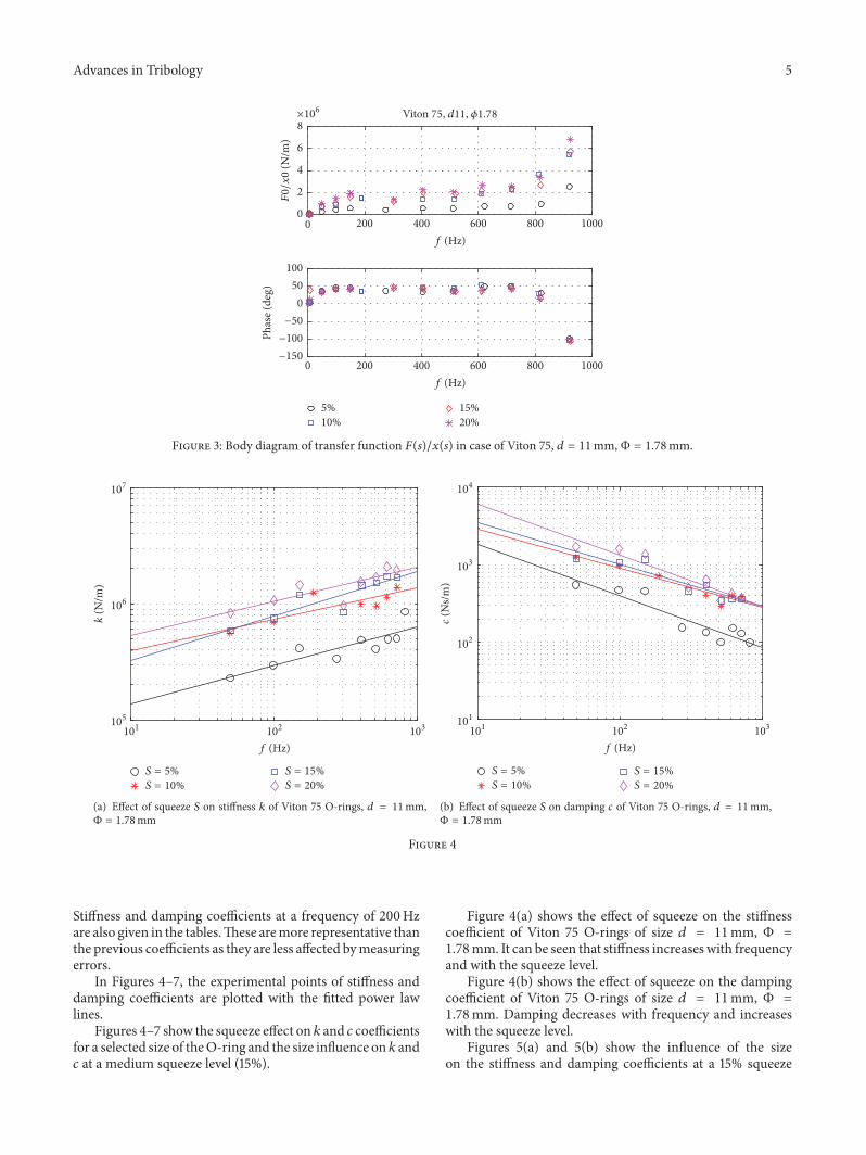
An example of Bode diagram is shown in Figure 3. It canbe noticed that, approaching the resonance frequency of thetest bench, the Bode diagram has a peak in the amplitude.Also the phase changes abruptly. For this reason, data atfrequencies over 850Hz are neglected.
3.1. Frequency Dependence. The results are summarized inTables 3–5 for Viton 75, Viton 90, and Kalrez, respectively.They are presented in the form of coefficients A, B, 𝛼, and 𝛽.

4 Advances in Tribology
Table 3: Summary of the results for Viton 75 O-ring.
𝑑 (mm) Φ (mm) S% 𝐴 ⋅ 106 𝛼 k200 (MN/m) 𝐵 ⋅ 106 𝛽 c200 (Ns/m)
11 1,78
5 0,0347 0,331 0,368 0,0293 −0,666 25310 0,131 0,268 0,887 0,0298 −0,508 79415 0,0666 0,384 1,032 0,0335 −0,544 69020 0,155 0,295 1,272 0,094 −0,66 847
11 2,6210 0,275 0,192 1,082 0,469 −0,923 64715 0,111 0,384 1,720 0,177 −0,673 145320 0,08 0,492 2,679 0,369 −0,735 1946
41 1,78
5 0,1644 0,474 4,8402 0,0328 −0,297 394010 0,1811 0,463 4,9298 0,0389 −0,311 422815 0,0550 0,631 4,9655 0,0320 −0,278 440520 0,1378 0,542 6,5927 0,0370 −0,273 5278
41 2,62
5 0,0791 0,51 3,0100 0,0115 −0,209 258410 0,0903 0,555 4,7403 0,0223 −0,254 364715 0,0958 0,56 5,2100 0,0286 −0,27 416420 0,1427 0,541 6,7758 0,0408 −0,291 5112
Table 4: Summary of the results for Viton 90 O-ring.
𝑑 (mm) Φ (mm) S% 𝐴 ⋅ 106 𝛼 k200 (MN/m) 𝐵 ⋅ 106 𝛽 c200 (Ns/m)
11 1,78
5 0,229 0,132 0,588 0,654 −1,006 49910 0,504 0,218 2,386 0,620 −0,917 89215 0,125 0,379 1,861 0,058 −0,557 108220 1,380 0,160 4,323 0,069 −0,462 2568
11 2,6210 1,428 0,114 3,221 0,460 −0,828 124915 5,602 0,072 9,385 22,750 −1,364 134820 0,472 0,416 9,188 11,280 −1,122 3758
41 1,78
5 0,0994 0,597 7,039 0,028 −0,245 486810 0,116 0,617 9,485 0,050 −0,296 604815 0,284 0,521 11,691 0,090 −0,333 840420 0,164 0,625 14,204 0,195 −0,443 8249
41 2,62
5 0,329 0,487 10,637 0,093 −0,390 575010 0,362 0,528 15,666 0,158 −0,421 782315 0,421 0,492 14,083 0,218 −0,463 800120 0,740 0,467 20,715 0,171 −0,387 10810
Table 5: Summary of the results for Kalrez O-ring (𝑑 = 11mm, Φ = 1.78mm).
Material S% 𝐴 ⋅ 106 𝛼 k200 (MN/m) 𝐵 ⋅ 106 𝛽 c200 (Ns/m)
Kalrez 4079
5 n.a.10 0,080 0,409 1,481 0,0776 −0,580 123715 0,214 0,314 2,012 0,193 −0,675 156220 0,168 0,391 2,736 0,211 −0,654 1983
Kalrez 6375
5 0,0312 0,429 0,666 0,0370 −0,564 66110 0,0266 0,514 1,042 0,0877 −0,637 93115 0,0371 0,512 1,433 0,284 −0,778 110220 0,0983 0,377 1,449 0,0478 −0,501 1339
Advances in Tribology 5
0
5%10%
15%20%
×106 Viton 75, d11, �휙1.78
200 400 600 800 10000f (Hz)
−150
−100
−50
050
100Ph
ase (
deg)
0
2
4
6
8
F0/
x0
(N/m
)
400 600 800 1000200f (Hz)
Figure 3: Body diagram of transfer function 𝐹(𝑠)/𝑥(𝑠) in case of Viton 75, 𝑑 = 11mm, Φ = 1.78mm.
S = 5%S = 10%
S = 15%S = 20%
102 103101
f (Hz)
105
106
107
k(N
/m)
(a) Effect of squeeze 𝑆 on stiffness 𝑘 of Viton 75 O-rings, 𝑑 = 11mm,Φ = 1.78mm
S = 5%S = 10%
S = 15%S = 20%
102 103101
f (Hz)
101
102
103
104
c(N
s/m
)
(b) Effect of squeeze 𝑆 on damping 𝑐 of Viton 75 O-rings, 𝑑 = 11mm,Φ = 1.78mm
Figure 4
Stiffness and damping coefficients at a frequency of 200Hzare also given in the tables.These aremore representative thanthe previous coefficients as they are less affected bymeasuringerrors.
In Figures 4–7, the experimental points of stiffness anddamping coefficients are plotted with the fitted power lawlines.
Figures 4–7 show the squeeze effect on 𝑘 and 𝑐 coefficientsfor a selected size of theO-ring and the size influence on 𝑘 and𝑐 at a medium squeeze level (15%).
Figure 4(a) shows the effect of squeeze on the stiffnesscoefficient of Viton 75 O-rings of size 𝑑 = 11mm, Φ =1.78mm. It can be seen that stiffness increases with frequencyand with the squeeze level.
Figure 4(b) shows the effect of squeeze on the dampingcoefficient of Viton 75 O-rings of size 𝑑 = 11mm, Φ =1.78mm. Damping decreases with frequency and increaseswith the squeeze level.
Figures 5(a) and 5(b) show the influence of the sizeon the stiffness and damping coefficients at a 15% squeeze

6 Advances in Tribology
105
106
107
108k
(N/m
)
102 103101
f (Hz)
d = 11 mm, �휙 = 1.78mmd = 11 mm, �휙 = 2.62mm
d = 41mm, �휙 = 1.78mmd = 41mm, �휙 = 2.62mm
(a) Effect of size on stiffness 𝑘 of Viton 75 O-rings, squeeze level 15%
102 103101
f (Hz)
d = 11 mm, �휙 = 1.78mmd = 11 mm, �휙 = 2.62mm
d = 41mm, �휙 = 1.78mmd = 41mm, �휙 = 2.62mm
102
103
104
105
c(N
s/m
)
(b) Effect of size on damping 𝑐 of Viton 75 O-rings, squeeze level 15%
Figure 5
S = 5%S = 10%
S = 15%S = 20%
103102101
f (Hz)
105
106
107
k(N
/m)
(a) Effect of squeeze 𝑆 on stiffness 𝑘 of Viton 90 O-rings, 𝑑 = 11mm,Φ = 1.78mm
S = 5%S = 10%
S = 15%S = 20%
103102101
f (Hz)
101
102
103
104
105
c(N
s/m
)
(b) Effect of squeeze 𝑆 on damping 𝑐 of Viton 90 O-rings, 𝑑 = 11mm,Φ = 1.78mm
Figure 6
level. Stiffness and damping coefficients increase both withdiameter 𝑑 and cross diameterΦ, although the influence ofΦis almost negligible when 𝑑 is high.This is in accordance withdata of paper [10], in which the influence of the cross sectiondiameter is negligible with an O-ring of internal diameter 𝑑of about 73mm.
Figures 6(a) and 6(b) show the effect of squeeze onstiffness and damping coefficients of Viton 90 O-rings of size𝑑 = 11mm, Φ = 1.78mm. It can be noticed that Viton 90 ismore rigid and has also a greater damping capability.
Similar trends are shown in Figures 7(a) and 7(b) pre-senting the influence of the size on the stiffness and damping

Advances in Tribology 7
d = 11 mm, �휙 = 1.78mmd = 11 mm, �휙 = 2.62mm
d = 41mm, �휙 = 1.78mmd = 41mm, �휙 = 2.62mm
105
106
107
108k
(N/m
)
102 103101
f (Hz)
(a) Effect of size on stiffness 𝑘 of Viton 90 O-rings, squeeze level 15%
d = 11 mm, �휙 = 1.78mmd = 11 mm, �휙 = 2.62mm
d = 41mm, �휙 = 1.78mmd = 41mm, �휙 = 2.62mm
101
102
103
104
105
c(N
s/m
)
103101 102
f (Hz)
(b) Effect of size on damping 𝑐 of Viton 90 O-rings, squeeze level 15%
Figure 7
103101 102
f (Hz)
105
106
107
108
k(N
/m)
d = 11 mm, = 1.78mmd = 11 mm, = 2.62mmd = 41mm, = 1.78mm
d = 41mm, = 2.62mmFrom [13]From [15]
102 103101
f (Hz)
102
103
104
105
c(N
s/m
)
d = 11 mm, = 1.78mmd = 11 mm, = 2.62mmd = 41mm, = 1.78mm
d = 41mm, = 2.62mmFrom [13]From [15]
Figure 8: Comparison of the results of Viton 75, squeeze level 15%, with those from [10, 11].
coefficients at a 15% squeeze level for Viton 90 O-rings. Bothstiffness and damping are greater in Viton 90 with respect toViton 70.
Literature data on these coefficients are very difficult to befound. Table 6 shows details aboutO-rings from [10, 11] testedwith the mass resonant method. Figure 8 compares theseresults with that of the present paper, with Viton material
and a squeeze level of 15%. Considering that stiffness anddamping should increase with the Shore hardness and withboth 𝑑 and Φ, coefficients from [11] are compatible with thatof 𝑑 = 41mm, as their Shore hardness and their cross sectiondiameter are lower. Furthermore the coefficients from [10] aregreater than that of 𝑑 = 41mm and squeeze 15% and also thiscomparison is good.
8 Advances in Tribology
0 5 15 2010% squeeze
0
1000
2000
3000
4000
5000
6000
c 200
(Ns/
m)
d = 11 mm, 𝜙 = 1.78mmd = 11 mm, 𝜙 = 2.62mm
d = 41mm, 𝜙 = 1.78mmd = 41mm, 𝜙 = 2.62mm
0 5 15 2010% squeeze
0
1
2
3
4
5
6
7k20
0(M
N/m
)
d = 11 mm, 𝜙 = 1.78mmd = 11 mm, 𝜙 = 2.62mm
d = 41mm, 𝜙 = 1.78mmd = 41mm, 𝜙 = 2.62mm
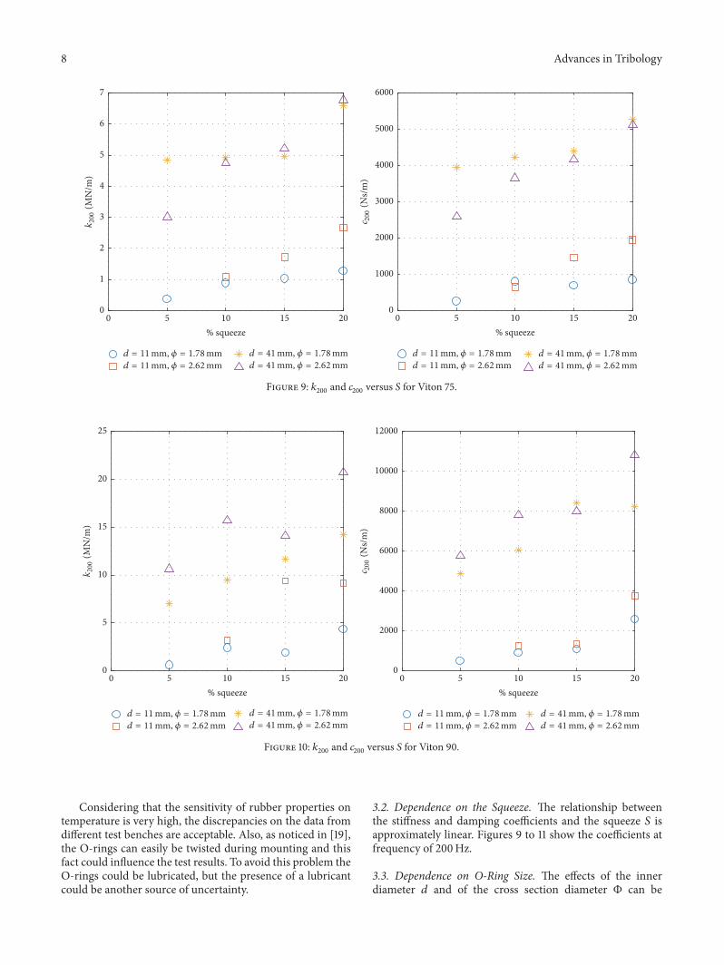
Figure 9: 𝑘200 and 𝑐200 versus 𝑆 for Viton 75.
0
5
10
15
20
25
k20
0(M
N/m
)
d = 11 mm, 𝜙 = 1.78mmd = 11 mm, 𝜙 = 2.62mm
d = 41mm, 𝜙 = 1.78mmd = 41mm, 𝜙 = 2.62mm
5 10 15 200% squeeze
0
2000
4000
6000
8000
10000
12000
c 200
(Ns/
m)
d = 11 mm, 𝜙 = 1.78mmd = 11 mm, 𝜙 = 2.62mm
d = 41mm, 𝜙 = 1.78mmd = 41mm, 𝜙 = 2.62mm
5 10 15 200% squeeze
Figure 10: 𝑘200 and 𝑐200 versus 𝑆 for Viton 90.
Considering that the sensitivity of rubber properties ontemperature is very high, the discrepancies on the data fromdifferent test benches are acceptable. Also, as noticed in [19],the O-rings can easily be twisted during mounting and thisfact could influence the test results. To avoid this problem theO-rings could be lubricated, but the presence of a lubricantcould be another source of uncertainty.
3.2. Dependence on the Squeeze. The relationship betweenthe stiffness and damping coefficients and the squeeze 𝑆 isapproximately linear. Figures 9 to 11 show the coefficients atfrequency of 200Hz.
3.3. Dependence on O-Ring Size. The effects of the innerdiameter 𝑑 and of the cross section diameter Φ can be

Advances in Tribology 9
Kalrez 4079Kalrez 6375
5 10 15 200% squeeze
500
1000
1500
2000
c 200
(Ns/
m)
Kalrez 4079Kalrez 6375
5 10 15 200% squeeze
0.5
1
1.5
2
2.5
3k20
0(M
N/m
)
Figure 11: 𝑘200 and 𝑐200 versus 𝑆 for Kalrez O-rings.
Table 6: Dimensions of the O-rings tested in [10, 11].
Rubber Φ (mm) 𝑑 (mm) Squeeze level TemperatureRef. [10] Viton 70 3.53 69 15% 21∘CRef. [11] Viton 70 1.73 41 28% n.a.
evaluated plotting the coefficients obtainedwith the followingratios:
𝑘200 = 𝑘200𝑑 ⋅ Φ ,𝑐200 = 𝑐200𝑑 ⋅ Φ .
(6)
The results are depicted in Figures 12 and 13. In firstapproximation it is possible to collapse the four trends intoone curve. In this way the properties of the O-rings can beidentified independently of their size:
𝑘200 = 𝐶 + 𝛾𝑆 (7a)
𝑐200 = 𝐷 + 𝛿𝑆. (7b)
The least squares procedure was adopted to fit the lineartrends to experimental data (see Appendix B). In theseequations the squeeze is expressed in percentage form (𝑆 = 5,10, 15, and 20). Table 7 summarizes the results.
4. Conclusions
In the present work the dynamic properties of rubberO-ringsare provided. The following conclusions can be made:
(i) Stiffness increases with frequency, while dampingdecreases.
Table 7: Coefficients for the identification of 𝑘200 and 𝑐200.Rubber 𝐶 (MN/m3) 𝛾 (MN/m3) 𝐷 (Ns/m3) 𝛿 (Ns/m3)Viton 75 22595 2610 2.069⋅107 1.800⋅106Viton 90 22915 10412 1.177⋅107 0.457⋅107
(ii) Stiffness and damping coefficients increase both withthe size of the O-ring (internal diameter 𝑑 and cross-sectional diameter Φ) and with the squeeze level.
(iii) A material with higher Shore hardness has higherstiffness and damping.
Formulas are provided to identify as a first approximationthe stiffness and damping coefficients of O-rings of generalsize. These formulas can be inserted in lumped parametersmodels of gas bearings to evaluate their increased stabilitywith the use of the O-rings.
Future interesting investigations could concern the veri-fication of these formulas with O-rings of different size. Alsothe effect of temperature could be taken into account settingup a temperature control.
Appendix
A. Interpolating Coefficients
Coefficients 𝐴 and 𝛼 are calculated solving the followinglinear system by least squares procedure:
[[[[[
1 log𝜔1...1 log𝜔𝑛
]]]]]{log𝐴𝛼 } =
{{{{{{{{{
log 𝑘1...log 𝑘𝑛
}}}}}}}}}. (A.1)
The pulsation vector is expressed in rad/s.

10 Advances in Tribology
50 15 2010% squeeze
×104
d = 11 mm, 𝜙 = 1.78mmd = 11 mm, 𝜙 = 2.62mmd = 41mm, 𝜙 = 1.78mm
d = 41mm, 𝜙 = 2.62mmInterp.
1
2
3
4
5
6
7
8
9
10k20
0/(d∗Φ)
(MN
/m3)
0 15 20105% squeeze
d = 11 mm, 𝜙 = 1.78mmd = 11 mm, 𝜙 = 2.62mmd = 41mm, 𝜙 = 1.78mm
d = 41mm, 𝜙 = 2.62mmInterp.
×107
1
2
3
4
5
6
7
8
c 200/(d∗Φ)
(Ns/m
3)
Figure 12: 𝑘200 and 𝑐200 versus 𝑆 for Viton 75.
50 15 2010% squeeze
0
2
4
6
8
10
12
14
c 200/(d∗Φ)
(Ns/m
3)
d = 11 mm, 𝜙 = 1.78mmd = 11 mm, 𝜙 = 2.62mmd = 41mm, 𝜙 = 1.78mm
d = 41mm, 𝜙 = 2.62mmInterp.
5 10 15 200% squeeze
0
0.5
1
1.5
2
2.5
3
3.5
k20
0/(d∗Φ)
(MN
/m3)
d = 11 mm, 𝜙 = 1.78mmd = 11 mm, 𝜙 = 2.62mmd = 41mm, 𝜙 = 1.78mm
d = 41mm, 𝜙 = 2.62mmInterp.
×107×105
Figure 13: 𝑘200 and 𝑐200 versus 𝑆 for Viton 90.

Advances in Tribology 11
Similar procedure was adopted for coefficients 𝐵 and 𝛽:[[[[[
1 log𝜔1...1 log𝜔𝑛
]]]]]{log𝐵𝛽 } =
{{{{{{{{{
log 𝑐1...log 𝑐𝑛
}}}}}}}}}. (A.2)
B. Extrapolating Coefficients
Coefficients 𝐶 and 𝛾 are calculated solving the followinglinear system by least squares procedure:
[[[[[
1 𝑆1...1 𝑆𝑛
]]]]]{𝐶𝛾} =
{{{{{{{{{
𝑘200,1...𝑘200,𝑛
}}}}}}}}}. (B.1)
The squeeze is expressed in percentage form.Similar procedure was adopted for coefficients𝐷 and 𝛿:
[[[[[
1 𝑆1...1 𝑆𝑛
]]]]]{𝐷𝛿} =
{{{{{{{{{
𝑐200,1...𝑐200,𝑛
}}}}}}}}}. (B.2)
Conflicts of Interest
The authors declare that they have no conflicts of interest.
Acknowledgments
The authors wish to acknowledge KU Leuven and Politecnicodi Torino for the financial support to this work.
References
[1] J. Kerr, “The onset and cessation of half speed whirl in air lubri-cated self pressurized journal bearings,” NEL Report No. 237,1966.
[2] S. Yoshimoto, “Improvement of static characteristics of an aero-static journal bearing using the elastic deformation of an O-ring,” Tribology International, vol. 20, no. 5, pp. 290–296, 1987.
[3] J. W. Powell and M. C. Tempest, “A study of high speedmachines with rubber stabilized air bearings,” ASME Journal ofLubrication Technology, vol. 90, pp. 701–708, 1968.
[4] Z. Kazimierski, “Stability threshold of the flexibly supportedhybrid gas journal bearings,” Journal of lubrication technology,vol. 101, pp. 451–457, 1979.
[5] D. A. Boffey and D. M. Desai, “An experimental investigationinto the rubber-stabilization of an externally-pressurized air-lubricated thrust bearing,” ASME Journal of Lubrication Tech-nology, vol. 102, pp. 65–70, 1980.
[6] S. Dousti, J. A. Kaplan, F. He, and P. E. Allaire, “Elastomer O-rings as centering spring in squeeze film dampers: Applicationto turbochargers,” in Proceedings of the ASME Turbo Expo 2013:Turbine Technical Conference and Exposition, GT 2013, June2013.
[7] S. Dousti, T. W. Dimond, P. E. Allaire, and H. E. Wood, “Timetransient analysis of horizontal rigid rotor supported with O-ring sealed squeeze film damper,” in Proceedings of the ASME2013 InternationalMechanical Engineering Congress and Exposi-tion, IMECE 2013, November 2013.
[8] K. Czołczynski and K. Marynowski, “Stability of symmetricalrotor supported in flexibly mounted, self-acting gas journalbearings,”Wear, vol. 194, no. 1-2, pp. 190–197, 1996.
[9] T. Waumans, J. Peirs, F. Al-Bender, and D. Reynaerts, “Aero-dynamic journal bearing with a flexible, damped supportoperating at 7.2 million DN,” Journal of Micromechanics andMicroengineering, vol. 21, no. 10, Article ID 104014, 2011.
[10] A. J. Smalley,M. S. Darlow, and R. K.Mehta, “The dynamic cha-racteristics of O-rings,” Journal of Mechanical Design, vol. 100,pp. 132–138, 1978.
[11] G. Belforte, F. Colombo, T. Raparelli, and V. Viktorov, “High-speed rotor with air bearingsmounted on flexible supports: Testbench and experimental results,” Journal of Tribology, vol. 130,no. 2, pp. 1–7, 2008.
[12] R. M. Christensen, Theory of Viscoelasticity, Academic Press,New York, NY, USA, 1982.
[13] N. Akturk and R. Gohar, “Damping the vibrations of a rigidshaft supported by ball bearings by means of external elas-tomeric O-ring dampers,” IMechE: J, Journal of EngineeringTribology, vol. 208, pp. 183–190, 1994.
[14] C. Zhi et al., “Finite element analysis of sealing characteristicsof the rubber O-ring for a mechanical seal,” Journal of SichuanUniversity: Engineering Science Edition, vol. 43, pp. 234–239,2011.
[15] C. Han, H. Zhang, and J. Zhang, “Structural Design and SealingPerformance Analysis of Biomimetic Sealing Ring,” AppliedBionics and Biomechanics, vol. 2015, Article ID 358417, 2015.
[16] Z. J. J. Gui, “Finite Element Analysis of Contact Pressure on O-ring,” Lubrication Engineering, vol. 2, p. 024, 2010.
[17] M. Darlow and E. Zorzi, “Mechanical Design Handbook forElastomers,” NASA Contractor Reports 3423, 1981.
[18] R. G. Wensel et al., “Friction and axial force/displacement cha-racteristics of elastomer seals in water,”ASLE paper, vol. 84-LC-6A-1, 1984.
[19] I. Green and I. Etsion, “Pressure and squeeze effects on thedynamic characteristics of the elastomer o-rings under smallreciprocating motion,” ASME Journal of Tribology, vol. 108, pp.439–445, 1986.
[20] A. Bormann and R. Gasch, “Damping and stiffness coefficientsof elastomer rings and their optimised application in rotordynamics: theoretical investigations and experimental valida-tion,” Australian Journal of Mechanical Engineering, vol. 1, pp.91–101, 2004.
[21] F. Colombo, T. Raparelli, and V. Viktorov, “Externally pres-surized gas bearings: A comparison between two supply holesconfigurations,” Tribology International, vol. 42, no. 2, pp. 303–310, 2009.
[22] F. Colombo, T. Raparelli, A. Trivella, and V. Viktorov, “Lumpedparameters models of rectangular pneumatic pads: Static anal-ysis,” Precision Engineering, vol. 42, pp. 283–293, 2015.
[23] F. Colombo, M. Moradi, T. Raparelli, A. Trivella, and V. Vik-torov, “Multiple holes rectangular gas thrust bearing: dynamicstiffness calculation with lumped parameters approach,” inAdvances in Italian Mechanism Science, vol. 47 of Mechanisms

12 Advances in Tribology
and Machine Science, pp. 421–429, Springer International Pub-lishing, 2017.
[24] G. Belforte, F. Colombo, T. Raparelli, A. Trivella, and V. Vik-torov, “Study of the static and dynamic performance of rectan-gular air pads by means of lumped parameters models,” inProceedings of the ASME 2012 11th Biennial Conference onEngineering Systems Design and Analysis, ESDA 2012, pp. 531–537, July 2012.

RoboticsJournal of
Hindawi Publishing Corporationhttp://www.hindawi.com Volume 2014
Hindawi Publishing Corporationhttp://www.hindawi.com Volume 2014
Active and Passive Electronic Components
Control Scienceand Engineering
Journal of
Hindawi Publishing Corporationhttp://www.hindawi.com Volume 2014
International Journal of
RotatingMachinery
Hindawi Publishing Corporationhttp://www.hindawi.com Volume 2014
Hindawi Publishing Corporation http://www.hindawi.com
Journal of
Volume 201
Submit your manuscripts athttps://www.hindawi.com
VLSI Design
Hindawi Publishing Corporationhttp://www.hindawi.com Volume 201
Hindawi Publishing Corporationhttp://www.hindawi.com Volume 2014
Shock and Vibration
Hindawi Publishing Corporationhttp://www.hindawi.com Volume 2014
Civil EngineeringAdvances in
Acoustics and VibrationAdvances in
Hindawi Publishing Corporationhttp://www.hindawi.com Volume 2014
Hindawi Publishing Corporationhttp://www.hindawi.com Volume 2014
Electrical and Computer Engineering
Journal of
Advances inOptoElectronics
Hindawi Publishing Corporation http://www.hindawi.com
Volume 2014
The Scientific World JournalHindawi Publishing Corporation http://www.hindawi.com Volume 2014
SensorsJournal of
Hindawi Publishing Corporationhttp://www.hindawi.com Volume 2014
Modelling & Simulation in EngineeringHindawi Publishing Corporation http://www.hindawi.com Volume 2014
Hindawi Publishing Corporationhttp://www.hindawi.com Volume 2014
Chemical EngineeringInternational Journal of Antennas and
Propagation
International Journal of
Hindawi Publishing Corporationhttp://www.hindawi.com Volume 2014
Hindawi Publishing Corporationhttp://www.hindawi.com Volume 2014
Navigation and Observation
International Journal of
Hindawi Publishing Corporationhttp://www.hindawi.com Volume 2014
DistributedSensor Networks
International Journal of