Embed Size (px)
Citation preview

Dynamic holographic interferometryby photorefractive crystals for quantitativedeformation measurements
Bruno Pouet and Sridhar Krishnaswamy
Aholographic interferometer that uses two-wavemixing in a photorefractive 1Bi12SiO202 crystal under anapplied ac field is described. The interferometer uses a repetitive sequence of separate record andreadout times to obtain quasi real-time holographic interferograms of vibrating objects. It is shownthat a good signal-to-noise ratio of the interferometer is obtained by turning off the object illuminationand the applied ac field during readout of the hologram. The good signal-to-noise ratio of the resultingholographic interferograms enables phase measurement, which allows for quantitative deformationanalysis. r 1996 Optical Society of America
1. Introduction
Dynamic holographic interferometry by photorefrac-tive crystals 1PRC’s2 was first demonstrated nearlytwo decades ago.1 Since then, various optical geom-etries have been used based on two-wave and four-wave mixing.2 Good fringe contrast was achievedby Troth and Dainty,3 who used a geometry thatutilized the phenomenon of anisotropic self-diffrac-tion proposed by Petrov et al.4 To date, most of theapplications with PRC’s have dealth with planewaves or specularly reflected beams, and very fewapplications have dealt with scattered beams fromdiffusely reflecting objects. With usual crystal sizesthe hologram dimension is typically limited to anarea of 10 mm 3 10 mm. The relatively small sizeof the hologram along with the relatively low holo-graphic photosensitivity and the high intrinsic opti-cal noise of the PRC’s is responsible for their limiteduse with diffusely reflecting objects.If quantitative deformation data are to be ex-
tracted from the holographic interferograms ob-tained from such diffusely reflecting objects, then itis essential that the signal intensity be made as highas possible and that every possible source of noise beminimized. A recent paper of Miridonov et al.5
The authors are with the Center for Quality Engineering andFailure Prevention, Department of Mechanical Engineering,Northwestern University, Evanston, Illinois 60208-3020.Received 7March 1995; revisedmanuscript received 10 October
1995.0003-6935@96@050787-08$06.00@0r 1996 Optical Society of America
studied the influence of the input-beam polarizationand the intensity ratio on the performance of aholographic interferometer with anisotropic self-diffraction. The signal-to-noise ratio 1SNR2 of suchinterferometers can be quite good owing to the 90°rotation of the diffracted polarization plane. If thediffusion mechanism of charge transport is utilized,the diffraction efficiency of the PRC’s is limited tosmall values, leading to poor signal intensities.Furthermore, the relatively large writing-beamangles required in this mode result in a rather slowtime response of the crystal. One can greatly en-hance the diffraction efficiency of the holographicgrating by applying an external electric field onto thecrystal and by reducing the writing-beam angle.An ac rather than a dc electric field is preferred sinceit leads to many advantages, including increasedstability, no requirement for uniform illumination ofthe crystal, and avoidance of the electrode shadow-ing problem.6 The application of an external elec-tric field unfortunately induces birefringence andthus modifies the polarization state of the diffractedand the signal beams.7 These polarization-statemodifications in turn can reduce the SNR.In this paper we present a holographic interferom-
eter based on two-wave mixing in a Bi12SiO20 1BSO2crystal. Particular attention is paid toward develop-ing an optimal configuration for the system such thatthe resulting holographic interferograms have asufficiently good SNR that quantitative deformationmaps can be obtained by means of a phase-unwrap-ping technique. The degradation in the SNR of theholographic interferograms that arises from the
10 February 1996 @ Vol. 35, No. 5 @ APPLIED OPTICS 787

optical activity 1which causes rotation of the plane ofpolarization2 and the crystal birefringence 1whichcauses elliptization of the polarization2 is investi-gated. We show that a good SNR of the interferom-eter is obtained by using separate hologram record-ing and readout times and by turning off the appliedac field during the readout of the hologram. Thequality of the resultant interferometer is demon-strated with near real-time visualization of holo-graphic double-exposure interferograms of vibratingstructures. It is shown that the good SNR of theresulting holograms enables phase measurement,which allows for quantitative deformation analysis.
2. Characterization of the Interferometer
A schematic of the principle of two-wave mixing in aPRC is shown in Fig. 1. An ac electric field isapplied to the BSO crystal. The two input beamsincident upon the crystal are labeled the reference orpump WR 1usually a plane wave2 and the object WO1which can be a speckled beam that emanates fromthe scatter from a diffuse object2, respectively. Thetwo input beams create a holographic volume grat-ing in the crystal. The output beams are the follow-ing: the transmitted reference beam WTR alongwith the diffracted object beam WDO, which propa-gate in the direction of the incident reference, andthe transmitted object beam WTO along with thediffracted reference beam WDR, which travel in thedirection of the incident object beam. The signal ofinterest is contained in the diffracted reference beamWDR, which is typically collected in a camera 1orphotodetector2, and all other light that is collected bythe camera is essentially noise that degrades thesignal. For obtaining a holographic interferogramwith a good SNR the intensity of the signal 1thediffracted reference beam2 needs to be as high aspossible, and the intensity of all other light thatcontributes to the noise 1the transmitted object beamand any scatter of the reference beam collected bythe photodetector2must be as small as possible.
Fig. 1. Principle of the holographic interferometer with two-wave mixing in BSO crystal.
788 APPLIED OPTICS @ Vol. 35, No. 5 @ 10 February 1996
For two-wave mixing in the cubic crystals, it hasbeen found8 that the optimal crystal orientation iswhen the optical surfaces of the crystal are parallelto the 11102 crystallographic planes and when thegrating vector and applied external electric field areparallel to the 31104 direction. The optimal setup,which leads to the highest diffraction efficiency andsensitivity, corresponds to a small writing-beamangle along with a high applied external electricfield.9 For incident reference- and signal-beam po-larizations along the 30014 axis, the beam diffractedby the hologram has its polarization plane rotated by90° with respect to the incident beams.4 An appro-priately aligned polarizer can be used to take advan-tage of the polarization rotation of the diffractedbeam to block the transmitted object beam andthereby provide an enhanced SNR.3,10,11 Further-more, it is found that, in order to compensate for thenatural optical activity of the crystal 1r 5 38° mm21
at l 5 514 nm2, we need a rotation of the inputpolarization w from the 30014 axis to obtain theoptimum diffraction efficiency.7
A. Maximization of the Signal Intensity
The diffraction efficiency is defined as the ratio of theintensity of the diffracted reference beam 1the signal2to the amount of incident reference: h 5 [email protected] is a parameter that has a major bearing on thequality of the dynamic holographic interferometer.For small refractive-index modulation, h is propor-tional to the square of the induced electric fieldinside the photorefractive crystal.12 We assumethat the holographic recording process leads to anexponential buildup12 of the induced electric field inthe crystal such that
E1t2 5 Esat31 2 exp12t@t24, 112
with t being the time constant and Esat being thevalue at saturation. It follows that the diffractionefficiency increases as
h1t2 5 hsat31 2 exp12t@t242, 122
where hsat is the value at saturation. At the earlystages of the recording process, Eq. 112 can be approxi-mated to a linear time dependence: E1t2 5 St, wherewe introduce the dynamic sensitivity as S 5 [email protected] to the dynamic nature of the holographicrecording process in a photorefractive crystal, theperformance of the interferometer is characterizedby the diffraction efficiency at saturation hsat for timescales much longer than the time response of thecrystal and by the dynamic sensitivity S for timescales much smaller than the time response of thecrystal.In a first experiment the optical configuration that
would lead to the best diffraction efficiency h for thechosen BSO system was experimentally determined.Incident plane waves from an argon-ion laser 1514nm2were used for the characterization of the photore-fractive crystal. We expected that the performance
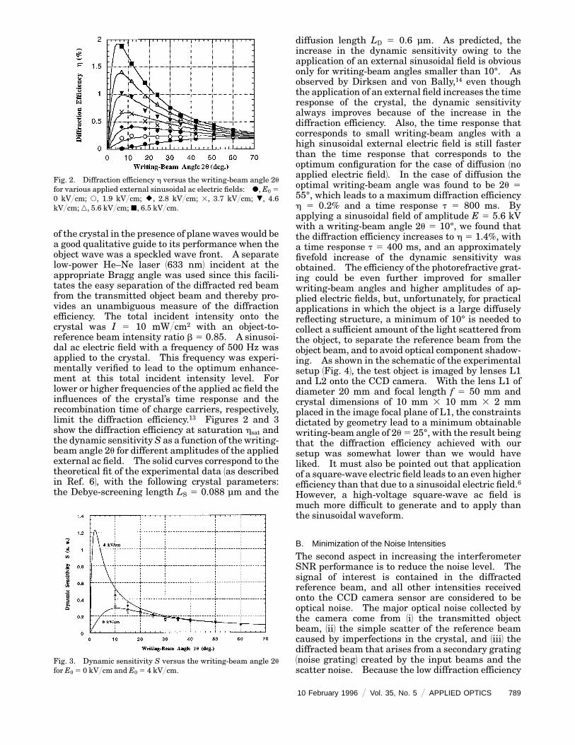
of the crystal in the presence of plane waves would bea good qualitative guide to its performance when theobject wave was a speckled wave front. A separatelow-power He–Ne laser 1633 nm2 incident at theappropriate Bragg angle was used since this facili-tates the easy separation of the diffracted red beamfrom the transmitted object beam and thereby pro-vides an unambiguous measure of the diffractionefficiency. The total incident intensity onto thecrystal was I 5 10 mW@cm2 with an object-to-reference beam intensity ratio b 5 0.85. A sinusoi-dal ac electric field with a frequency of 500 Hz wasapplied to the crystal. This frequency was experi-mentally verified to lead to the optimum enhance-ment at this total incident intensity level. Forlower or higher frequencies of the applied ac field theinfluences of the crystal’s time response and therecombination time of charge carriers, respectively,limit the diffraction efficiency.13 Figures 2 and 3show the diffraction efficiency at saturation hsat andthe dynamic sensitivityS as a function of the writing-beam angle 2u for different amplitudes of the appliedexternal ac field. The solid curves correspond to thetheoretical fit of the experimental data 1as describedin Ref. 62, with the following crystal parameters:the Debye-screening length LS 5 0.088 µm and the
Fig. 2. Diffraction efficiency h versus the writing-beam angle 2u
for various applied external sinusoidal ac electric fields: d, E0 5
0 kV@cm; s, 1.9 kV@cm; U, 2.8 kV@cm; 3, 3.7 kV@cm; ., 4.6kV@cm; n, 5.6 kV@cm; j, 6.5 kV@cm.
Fig. 3. Dynamic sensitivity S versus the writing-beam angle 2u
for E0 5 0 kV@cm and E0 5 4 kV@cm.
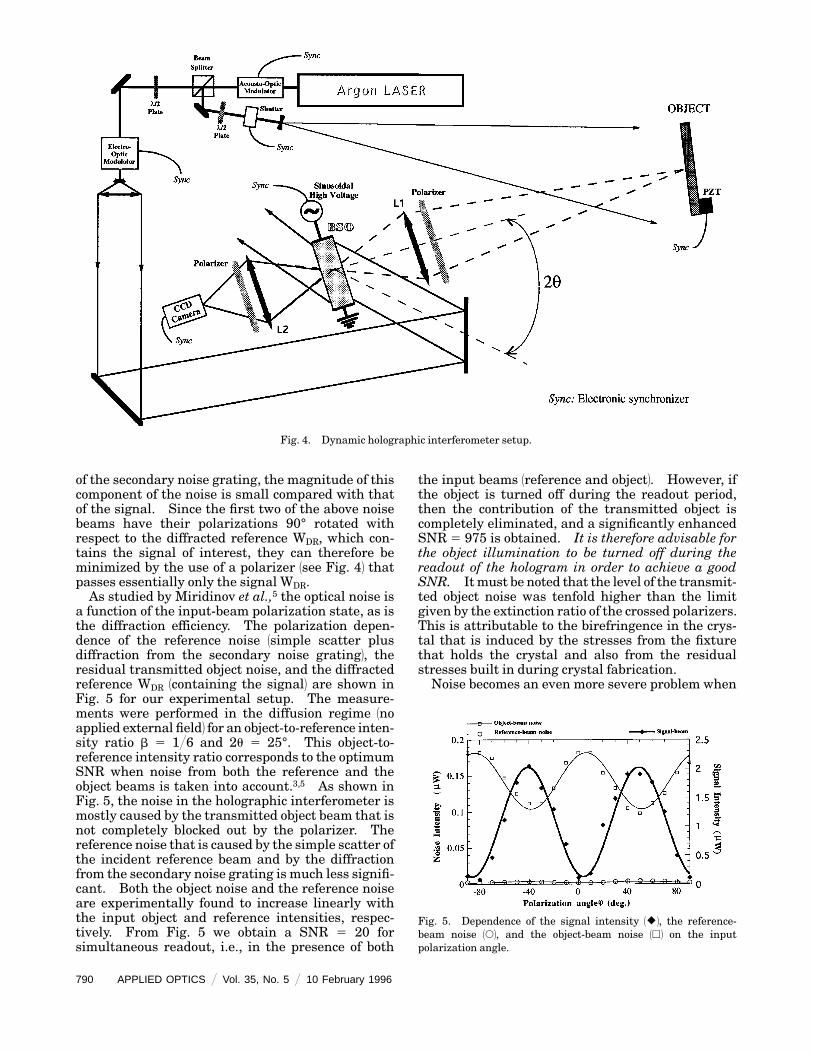
diffusion length LD 5 0.6 µm. As predicted, theincrease in the dynamic sensitivity owing to theapplication of an external sinusoidal field is obviousonly for writing-beam angles smaller than 10°. Asobserved by Dirksen and von Bally,14 even thoughthe application of an external field increases the timeresponse of the crystal, the dynamic sensitivityalways improves because of the increase in thediffraction efficiency. Also, the time response thatcorresponds to small writing-beam angles with ahigh sinusoidal external electric field is still fasterthan the time response that corresponds to theoptimum configuration for the case of diffusion 1noapplied electric field2. In the case of diffusion theoptimal writing-beam angle was found to be 2u 555°, which leads to a maximum diffraction efficiencyh 5 0.2% and a time response t 5 800 ms. Byapplying a sinusoidal field of amplitude E 5 5.6 kVwith a writing-beam angle 2u 5 10°, we found thatthe diffraction efficiency increases to h 5 1.4%, witha time response t 5 400 ms, and an approximatelyfivefold increase of the dynamic sensitivity wasobtained. The efficiency of the photorefractive grat-ing could be even further improved for smallerwriting-beam angles and higher amplitudes of ap-plied electric fields, but, unfortunately, for practicalapplications in which the object is a large diffuselyreflecting structure, a minimum of 10° is needed tocollect a sufficient amount of the light scattered fromthe object, to separate the reference beam from theobject beam, and to avoid optical component shadow-ing. As shown in the schematic of the experimentalsetup 1Fig. 42, the test object is imaged by lenses L1and L2 onto the CCD camera. With the lens L1 ofdiameter 20 mm and focal length f 5 50 mm andcrystal dimensions of 10 mm 3 10 mm 3 2 mmplaced in the image focal plane of L1, the constraintsdictated by geometry lead to a minimum obtainablewriting-beam angle of 2u 5 25°, with the result beingthat the diffraction efficiency achieved with oursetup was somewhat lower than we would haveliked. It must also be pointed out that applicationof a square-wave electric field leads to an even higherefficiency than that due to a sinusoidal electric field.6However, a high-voltage square-wave ac field ismuch more difficult to generate and to apply thanthe sinusoidal waveform.
B. Minimization of the Noise Intensities
The second aspect in increasing the interferometerSNR performance is to reduce the noise level. Thesignal of interest is contained in the diffractedreference beam, and all other intensities receivedonto the CCD camera sensor are considered to beoptical noise. The major optical noise collected bythe camera come from 1i2 the transmitted objectbeam, 1ii2 the simple scatter of the reference beamcaused by imperfections in the crystal, and 1iii2 thediffracted beam that arises from a secondary grating1noise grating2 created by the input beams and thescatter noise. Because the low diffraction efficiency
10 February 1996 @ Vol. 35, No. 5 @ APPLIED OPTICS 789
7
Fig. 4. Dynamic holographic interferometer setup.
of the secondary noise grating, the magnitude of thiscomponent of the noise is small compared with thatof the signal. Since the first two of the above noisebeams have their polarizations 90° rotated withrespect to the diffracted reference WDR, which con-tains the signal of interest, they can therefore beminimized by the use of a polarizer 1see Fig. 42 thatpasses essentially only the signal WDR.As studied by Miridinov et al.,5 the optical noise is
a function of the input-beam polarization state, as isthe diffraction efficiency. The polarization depen-dence of the reference noise 1simple scatter plusdiffraction from the secondary noise grating2, theresidual transmitted object noise, and the diffractedreference WDR 1containing the signal2 are shown inFig. 5 for our experimental setup. The measure-ments were performed in the diffusion regime 1noapplied external field2 for an object-to-reference inten-sity ratio b 5 1@6 and 2u 5 25°. This object-to-reference intensity ratio corresponds to the optimumSNR when noise from both the reference and theobject beams is taken into account.3,5 As shown inFig. 5, the noise in the holographic interferometer ismostly caused by the transmitted object beam that isnot completely blocked out by the polarizer. Thereference noise that is caused by the simple scatter ofthe incident reference beam and by the diffractionfrom the secondary noise grating is much less signifi-cant. Both the object noise and the reference noiseare experimentally found to increase linearly withthe input object and reference intensities, respec-tively. From Fig. 5 we obtain a SNR 5 20 forsimultaneous readout, i.e., in the presence of both
90 APPLIED OPTICS @ Vol. 35, No. 5 @ 10 February 1996
the input beams 1reference and object2. However, ifthe object is turned off during the readout period,then the contribution of the transmitted object iscompletely eliminated, and a significantly enhancedSNR 5 975 is obtained. It is therefore advisable forthe object illumination to be turned off during thereadout of the hologram in order to achieve a goodSNR. Itmust be noted that the level of the transmit-ted object noise was tenfold higher than the limitgiven by the extinction ratio of the crossed polarizers.This is attributable to the birefringence in the crys-tal that is induced by the stresses from the fixturethat holds the crystal and also from the residualstresses built in during crystal fabrication.Noise becomes an even more severe problem when
Fig. 5. Dependence of the signal intensity 1U2, the reference-beam noise 1s2, and the object-beam noise 1h2 on the inputpolarization angle.

an external ac field is applied to enhance the effi-ciency of the interferometer. This is due to thebirefringence induced by the electric field, which, inconjunction with the optical activity, transforms theincident linear polarizations into elliptical polariza-tions for the output. Owing to the time-varyingnature of the applied ac field, the state 1ellipticity2 ofthe output polarization also varied with time, and itis no longer possible to use a quarter-wave plate andpolarizer combination to block the undesired trans-mitted object beam WTO 1if it is left on during thereadout phase2 and the undesired noise from thescatter of the reference. This was borne out byexperiments in which we found that, when a field of5.6 kV@cm was applied to the crystal, the opticalnoise jumped from 5 nW up to 600 nW, which was afactor much greater than the improvement obtainedfor the diffraction efficiency. From this we concludethat the applied ac field must be turned off during theread-out of the hologram. In this case, birefrin-gence is no longer induced during readout, and thetransmitted object-beam 1if it is left on2 and thescattered reference-beam polarizations stay linear,as in the case of diffusion, and can be essentiallyblocked out by the polarizers.In view of the above considerations we see that the
optimum configuration for the dynamic holographicinterferometer is obtained through as small awriting-beam angle and as large an applied external ac fieldas possible. This configuration is characterized bya higher efficiency and sensitivity of the hologramthan in the case of the optimum setup for the case ofdiffusion. The applied ac field allows us to enhancethe photorefractive effect without the need for theuniform illumination and the phase shifting of thereference beam usually associated with applied dcfields.6 In order to achieve a good SNR, we turn offthe object beam during the readout of the hologram.Furthermore, the ac field is also turned off duringthe readout of the hologram in order to minimize thenoise from the scattered reference.
3. Vibrational-Deformation Measurements
The dynamic holographic interferometer describedabove has been used to quantitatively obtain thedeformations associated with resonant vibrationalmodes of acoustically stressed structures.3,10 To getthe best SNR, the recording and the reading aresynchronized with the applied ac field and the illumi-nation as described in Fig. 6. With continuousillumination during recording the resulting time-average fringes are described by a Bessel-functiondependence regarding the amplitude of the objectdisplacement. A major drawback of this is that itleads to a lower fringe contrast for higher amplitudedisplacements. By use of various schemes of timemodulation of the amplitude, various fringe func-tions can be obtained.15 By pulsing of the lightaccording to the extrema of the acoustic vibrationaldisplacements, a double-exposure hologram is formedsuch that the intensity recorded on the camera upon
readout of the hologram exhibits fringes with acosine dependence on the deformation:
I1 5 A11 1 B cos 2M2, 132
where A and B are possibly spatially varying ampli-tude terms of little interest except that they have aneffect on the fringe visibility. The signal of interestis M, which is related to the spatially varyingdeformation amplitude of the harmonically vibrat-ing object. This is the fringe function that is real-ized in our setup by use of the acousto-optic modula-tor shown in Fig. 4, which synchronously pulses thelight during the recording process according to theextrema of the acoustic stressing, as shown in Fig. 6.In our experiment a duty cycle of ,23% is able togive reasonable cosine fringes with still enoughintensity for recording the holographic interferogram.During the readout of the hologram the external fieldand the object illumination are turned off in order tominimize noise, and the reference illumination iscontinuous, leading to a faster reconstruction. Wemust note that, because of the destructive nature ofthe readout, the diffraction efficiency drops duringthe readout of the hologram.Figure 7 shows the application of this technique to
the detection of vibration modes of a piezoelectricmembrane of 2.5-cm diameter vibrating at 2.7 kHz.The integration time of the CCD is set at 30 ms, andthe repetition rate of the record–readout–erase pro-cess is,1 s. Figure 71A2 corresponds to the classicaltechnique with simultaneous continuous recordingand reading, and Fig. 71B2 results from the synchro-nized but separate record and readout process with-out application of the external ac field. The latterscheme clearly improves the SNR of the holograms.Figure 8 corresponds to a clamped circular alumi-num plate vibrating at 15 kHz. The diameter of theillumination area is 15 cm. Without the externalelectric field the maximum gray level is limited,showing that the diffracted signal beam is not strongenough. By applying the external electric field of
Fig. 6. Timing diagram.
10 February 1996 @ Vol. 35, No. 5 @ APPLIED OPTICS 791

amplitude E 5 5.6 kV@cm, we clearly enhance thediffraction efficiency. With the same integrationtime onto the CCD, the gray level reaches saturationon most of the sensor area, and a shorter writingtime could therefore be used.The SNR of the holographic interferograms ob-
tained with this setup is sufficiently good that quan-titative phase measurements can be obtained by theacquisition of a set of phase shifted images.16 Thisis demonstrated by the results in Fig. 9, which showthe holographic fringes from the above-describedclamped circular plane vibrating at 15 kHz. Asequence of three interferograms was obtained asshown in Fig. 9. An optical phase shift was intro-duced by means of the electro-optic modulator in thereference beam during the recording process be-tween the time of the maximum and the minimumacoustic deformation. The first hologram of thesequence 3Fig. 91A24 had no phase shift between themaximum and the minimum deformation, and theresulting fringe function was as given by Eq. 132.In the second hologram of the sequence 3Fig. 91B24 a
Fig. 7. Piezoelectricmembrane vibrating at 2.7 kHz: 1A2 continu-ous readout and 1B2 separate readout.
792 APPLIED OPTICS @ Vol. 35, No. 5 @ 10 February 1996
phase shift of 2p@2 and 1p@2 was introduced at theminimum and the maximum deformation, respec-tively, such that the fringe function obtained was
I2 5 A11 2 B cos 2M2. 142
In the third hologram 3Fig. 91C24 a phase shift of 0 and1p@2 was introduced at the minimum and themaximum deformation, respectively, such that thefringe function obtained was
I3 5 A11 1 B sin 2M2. 152
The deformation signal of interest M can then beextracted by
tan 2M 52I3 2 1I1 1 I22
I2 2 I1. 162
The above is valid everywhere except locally at thedead pixels where the spatially varying term Bhappens to be near zero—a condition that could arisefrom the speckled nature of the object beam and alsofrom the other noise contributors. The advantageof using a holographic interferometry setup with a
Fig. 8. Clamped circular plate vibrating at 15 kHz with separatereadout: 1A2 diffusion 1E0 5 02 and 1B2with an external sinusoidalelectric field 1E0 5 5.6 kV@cm2.
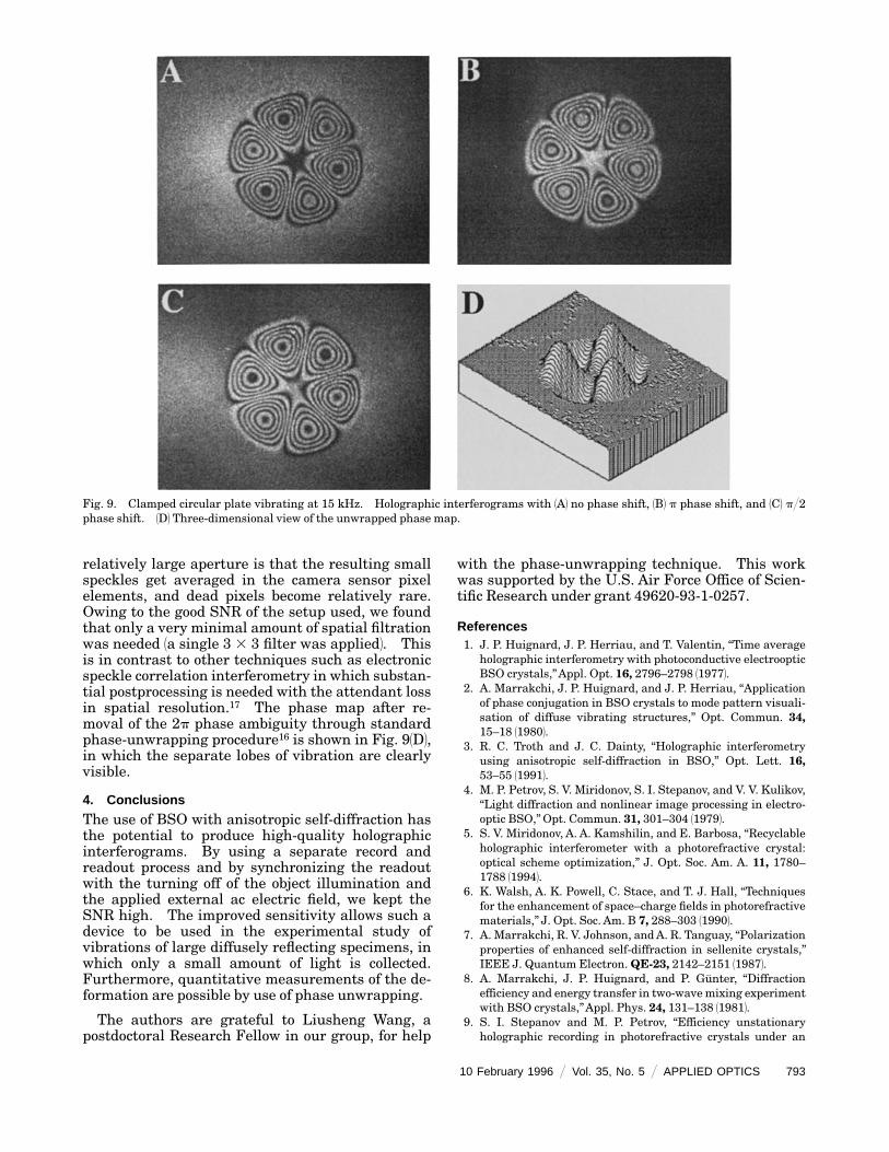
Fig. 9. Clamped circular plate vibrating at 15 kHz. Holographic interferograms with 1A2 no phase shift, 1B2 p phase shift, and 1C2 p@2phase shift. 1D2 Three-dimensional view of the unwrapped phase map.
relatively large aperture is that the resulting smallspeckles get averaged in the camera sensor pixelelements, and dead pixels become relatively rare.Owing to the good SNR of the setup used, we foundthat only a very minimal amount of spatial filtrationwas needed 1a single 3 3 3 filter was applied2. Thisis in contrast to other techniques such as electronicspeckle correlation interferometry in which substan-tial postprocessing is needed with the attendant lossin spatial resolution.17 The phase map after re-moval of the 2p phase ambiguity through standardphase-unwrapping procedure16 is shown in Fig. 91D2,in which the separate lobes of vibration are clearlyvisible.
4. Conclusions
The use of BSO with anisotropic self-diffraction hasthe potential to produce high-quality holographicinterferograms. By using a separate record andreadout process and by synchronizing the readoutwith the turning off of the object illumination andthe applied external ac electric field, we kept theSNR high. The improved sensitivity allows such adevice to be used in the experimental study ofvibrations of large diffusely reflecting specimens, inwhich only a small amount of light is collected.Furthermore, quantitative measurements of the de-formation are possible by use of phase unwrapping.
The authors are grateful to Liusheng Wang, apostdoctoral Research Fellow in our group, for help
with the phase-unwrapping technique. This workwas supported by the U.S. Air Force Office of Scien-tific Research under grant 49620-93-1-0257.
References1. J. P. Huignard, J. P. Herriau, and T. Valentin, ‘‘Time average
holographic interferometry with photoconductive electroopticBSO crystals,’’Appl. Opt. 16, 2796–2798 119772.
2. A. Marrakchi, J. P. Huignard, and J. P. Herriau, ‘‘Applicationof phase conjugation in BSO crystals to mode pattern visuali-sation of diffuse vibrating structures,’’ Opt. Commun. 34,15–18 119802.
3. R. C. Troth and J. C. Dainty, ‘‘Holographic interferometryusing anisotropic self-diffraction in BSO,’’ Opt. Lett. 16,53–55 119912.
4. M. P. Petrov, S. V. Miridonov, S. I. Stepanov, and V. V. Kulikov,‘‘Light diffraction and nonlinear image processing in electro-optic BSO,’’ Opt. Commun. 31, 301–304 119792.
5. S. V. Miridonov, A. A. Kamshilin, and E. Barbosa, ‘‘Recyclableholographic interferometer with a photorefractive crystal:optical scheme optimization,’’ J. Opt. Soc. Am. A. 11, 1780–1788 119942.
6. K. Walsh, A. K. Powell, C. Stace, and T. J. Hall, ‘‘Techniquesfor the enhancement of space–charge fields in photorefractivematerials,’’ J. Opt. Soc. Am. B 7, 288–303 119902.
7. A. Marrakchi, R. V. Johnson, andA. R. Tanguay, ‘‘Polarizationproperties of enhanced self-diffraction in sellenite crystals,’’IEEE J. Quantum Electron.QE-23, 2142–2151 119872.
8. A. Marrakchi, J. P. Huignard, and P. Gunter, ‘‘Diffractionefficiency and energy transfer in two-wavemixing experimentwith BSO crystals,’’Appl. Phys. 24, 131–138 119812.
9. S. I. Stepanov and M. P. Petrov, ‘‘Efficiency unstationaryholographic recording in photorefractive crystals under an
10 February 1996 @ Vol. 35, No. 5 @ APPLIED OPTICS 793

external alternating electric field,’’ Opt. Commun. 53, 292–295 119852.
10. J. P. Herriau, J. P. Huignard,A. G.Apostolidis, and S.Mallick,‘‘Polarization properties in two wave mixing with movinggrating in photorefractive BSO crystals: application to dy-namic interferometry,’’ Opt. Commun. 56, 141–144 119852.
11. A. A. Kamshilin, E. V. Mokrushina, and M. P. Petrov, ‘‘Adap-tive holographic interferometers operating through self-diffraction of recording beams in photorefractive crystals,’’Opt. Eng. 28, 580–585 119892.
12. P.Yeh, Introduction to Photorefractive Nonlinear Optics 1Wiley,NewYork, 19932.
13. C. Besson, J. M. C. Jonathan, A. Villing, G. Pauliat, and G.
794 APPLIED OPTICS @ Vol. 35, No. 5 @ 10 February 1996
Roosen, ‘‘Influence of alternating field frequency on enhancedphotorefractive gain in two-beam coupling,’’ Opt. Lett. 14,1359–1361 119892.
14. D. Dirksen and G. von Bally, ‘‘Holographic double-exposureinterferometry in near real time with photorefractive crystal,’’J. Opt. Soc. Am. B 11, 1858–1863 119942.
15. C. C.Aleksoff, ‘‘Temporally modulated holography,’’Appl. Opt.10, 1329–1341 119712.
16. K. Creath, ‘‘Phase-measurement interferometry techniques,’’Prog. Opt. 26, 351–393 119882.
17. L.-S. Wang and S. Krishnaswamy, ‘‘Additive-subtractivespeckle interferometry: extraction of phase data in noisyenvironments,’’ Opt. Eng. 1to be published2.


![[Click here are type Paper Title] - Université Laval · Web viewOptical methods, based on holographic interferometry, have been widely applied as diagnostic tools in the conservation](https://img.pdfslide.net/doc/110x75/5ece017757b2e565dd3c1d4c/click-here-are-type-paper-title-universit-laval-web-view-optical-methods.jpg)