Embed Size (px)
Citation preview

ORIGINAL PAPER
Dynamic In Situ Measurements of Frictional Heatingon an Isolated Surface Protrusion
Alexander I. Bennett • Kyle G. Rowe •
W. Gregory Sawyer
Received: 22 November 2013 / Accepted: 29 April 2014 / Published online: 14 May 2014
� Springer Science+Business Media New York 2014
Abstract Problems in the subject of frictional heating
have been studied extensively, yet their complexity
remains a barrier to further understanding. This study
simplifies the frictional heating problem by examining the
temperature rise due to a heat source of prescribed geom-
etry. A single positive feature on the sliding face of the
countersurface causes a local temperature rise. The cylin-
drical feature has a diameter of 150 lm and aspect ratio of
0.1 and slides under the larger contact area whose contact
width is *600 to *750 lm. An infrared camera, acquiring
at 870 Hz, observed the temperature rise at the contact
interface between the feature and the rubber pin. The
applied force for all tests was 200 mN, and the sliding
velocity was varied from 10 to 200 mm/s. Maximum
temperature rises of *1–17 �C and average temperature
rises of *1–8 �C were measured. Measured values were
compared to the Jaeger’s frictional heating models for
sliding contacts.
Keywords Friction � Wear � Thermal tribology �Elastomer
1 Introduction
Frictional heating in sliding contacts is unavoidable and
may profoundly affect the tribological and mechanical
properties of the materials in the system [1–5]. At the high
sliding speeds and loading conditions that are necessary to
induce measurable frictional heating in ceramic and
metallic contacts, the thermal behavior due to surface
roughness is especially difficult to analyze [6–8]. Due to
high friction, micro-scale elastomeric contacts demonstrate
appreciable temperature rises under much more controlla-
ble and measurable sliding conditions despite unpredict-
able contact geometries.
A broad range of thermal measurement methods, ranging
from thin film and dynamic thermocouples to radiometric
(infrared) measurements [1, 9–17], have been applied to
monitor contact temperature [18–20]. These methods have
largely been limited to spot analysis, which neglect the
spatial distribution of temperature data. A full-field infrared
method, as developed by Rowe et al. [12], is capable of
simultaneously mapping temperature changes over the full
contact area, reducing the analytical difficulties presented by
areal and geometric complexity [17]. This method can be
applied to contacts between any materials for systems with
an infrared (IR) transparent countersample and IR opaque
pin.
Established models for the frictional heating problem
have been proven for ideal circumstances such as smooth
geometries, known systems, and idealized materials [21–
30]. Due to the aforementioned barriers to measurement as
well as the expansive nature of the problem, making fun-
damental measurements becomes increasingly difficult.
The ideal system for infrared measurement of heating in
sliding contacts would involve set geometries with appre-
ciable heating at low speeds and loads.
Building on the work done by Rowe et al. [17], an
experiment has been designed in which the temperature
rise due to a prescribed geometry moving through contact
is measured. A micro-sized positive feature was deposited
A. I. Bennett � K. G. Rowe � W. Gregory Sawyer (&)
Department of Mechanical and Aerospace Engineering,
University of Florida, Gainesville, FL 32611, USA
e-mail: [email protected]
W. Gregory Sawyer
Department of Material Science and Engineering, University of
Florida, Gainesville, FL 32611, USA
123
Tribol Lett (2014) 55:205–210
DOI 10.1007/s11249-014-0347-7

on the surface of the CaF2 countersample in the sliding
path of the sample. Local temperature rises of the feature
are appreciable over the temperature rise of the global
contact even at sliding speeds as low as 10 mm/s. The
maximum and average temperature of the feature follows
the classical thermal heating models of Jaeger. Addition-
ally, the range of sliding speeds used may have crossed two
frictional heating regimes, which, with further investiga-
tion, may lead to a better understanding of sliding contact
frictional heating relative to surface roughness.
2 Asperity Contact Temperature Testing
2.1 Instrumentation and Analysis
A pin-on-disk, in situ thermal micro-tribometer was used
for all tests conducted in this experiment where contact is
made between a rubber hemisphere on a 3-mm-thick
cylindrical optical window [17]. The rubber, Viton A, is
pressed into contact with the calcium fluoride disk, and the
sample is held stationary, while the disk is rotated in a ring-
bearing stage, driven by a servo motor. Loading and
positioning of the sample are controlled by manual
micrometer stages and held constant during testing. Two
capacitance probes attached to a rectilinear cantilever
transduce displacements into voltages which are then
converted into force measurements.
The work done to overcome the friction between the
rubber pin and the rotating calcium fluoride (CaF2) disk
causes heat to be generated within the contact. The infrared
radiation emitted by the sample is then measured by an IR
camera (FLIR SC7650) and related to temperature. The
indium antimonide detector is sensitive to radiation wave-
lengths between 3 and 5 lm where the CaF2 countersample
transmits up to 92 % of incident IR. At quarter frame res-
olution (128 9 160 pixels at 5 lm/pixel), the camera is
capable of acquiring at 870 Hz. LabVIEWTM was used for
instrument control and data acquisition. Post-processing of
data was performed in MATLAB�.
Tests were conducted at a prescribed load of 200 mN
and contact pressure of *620 kPa. One sliding speed
was used for each test and varied from 10 mm/s up to
200 mm/s. Each test lasted *22 s and was imaged at
870 Hz. Frames were acquired for each pass of the feature
through the field of view of the camera (Fig. 1c). The
asperity was tracked frame by frame using an algorithm,
designed in house, that assigns a region of interest to the
cylindrical asperity for all frames in which it was visible
between the pin and the countersample (Fig. 1b).
For every video, the frames where the feature appeared
were separated from the rest of the video. Image-editing
tools in MATLAB were applied to each of the frames
which isolated the feature from the rest of the image using
a region of interest overlay. As the frames progressed, the
region of interest moved according to predicted values of
the features location. The dimensions and location of the
ROI were then applied to the temperature data of the
image. The average and maximum temperatures of the
isolated regions were recorded. The distance, s, is mea-
sured from the center of the image to the center of the
ROI.
21.5 °C
19.8 °C
19.1 °C
18.4 °C
17.7 °C
17.0 °C
16.3 °C
15.9 °C
Nominal Contact Area Field of View
s
Feature
t = 2.3 ms
150 µmV(asperity velocity)
Ff(friction force)
P(pin)
Fn(normal load)+s
at edge of contact: s = rr
18 µm
~20 µm
21.5 °C
19.8 °C
19.1 °C
18.4 °C
17.7 °C
17.0 °C
16.3 °C
15.9 °C
t = 0 ms
t = 5 ms
Rubber Impengement
Temperature Developmentthrough Contact
a b
c
800 µm
640 µm
s = 0
Fig. 1 a Schematic of contact
between the pin, countersurface,
and positive feature. As the
feature moves into contact, it
displaces the Viton A pin.
b Data analysis scheme of the
feature as it moves through the
global contact. The position of
the pin is measured from the
center of apparent contact of the
pin with the countersurface to
the center of the feature. c The
temperature development as the
feature moves under contact
shows a correlation with the
pressure distribution in the
contact. Highest temperatures
manifest near the center of
contact where the highest local
pressures exist
206 Tribol Lett (2014) 55:205–210
123

2.2 Materials
Viton A half-spheres were used as the pin material in these
studies. Viton A is considered hard relative to other rubbers
with a rating of 70A on the shore durometer scale, an
elastic modulus of 4–8 MPa, and a thermal conductivity of
0.22 W/m K. The average surface roughness, measured
using a scanning white light interferometer (Veeco�
NT7100), was found to be 1.46 lm.
Calcium fluoride was used as the countersample. Similar
to other ionic solids, CaF2 is transmissive in the infrared
spectrum and exhibits 92–95 % transmission throughout
the 0.2- to 6.5-lm wave band; this range encompasses the
3–5 lm range in which the FLIR SC7650 is capable of
measuring. Due to its hardness and thermal conductivity of
9.71 W/m K, as well as optical transmission, CaF2 is an
ideal choice as a countersample.
To produce the positive feature on the surface of the
countersample, an 18-lm layer of a common photoresist epoxy,
SU-8, was spun coat onto the CaF2. A photomask was then
applied for UV curing in order to produce patterns on the disk.
The desired pattern was a single cylinder, 18 lm tall and
150 lm in diameter at a disk radius of 15.725 mm. After cur-
ing, the excess uncured photomask was dissolved away using
propylene glycol monomethyl ether acetate. The deposition
process left an optically smooth positive feature on the CaF2 as
seen in Fig. 2. SU-8 has a thermal conductivity of 0.2 W/m K
which matches well with the thermal conductivity of the pin.
3 Results
The average temperature rise of the surface feature (above
ambient) ranged from 0.5 �C, for the slowest sliding
speed test, to 7 �C, for the fastest. The maximum tem-
perature rise followed the same trend with temperature
rises from 1 to 18 �C. A characteristic image for each test
is displayed in Fig. 3. Ambient and global contact tem-
perature, friction coefficient, and load did not change
appreciably during the experiments. Maximum and aver-
age temperatures of the feature for each test are given in
the table in Fig. 6.
The center of the feature’s position, s, as measured from
the center of global contact, was recorded for all frames
where the feature was in view. Position data were then
binned in 25-lm increments; the standard deviation of the
temperature for each bin is plotted in Fig. 4. In some tests,
18.25 µm
18.69 µm
b Worn
a Nascent
Fn Ffω
IR ImageArea 640 x 800 µm
CaF2 counter-sample
pinsurfacefeature
Sliding Direction
Sliding Direction
A
A
18.5 µm
150 µm
152.83 µm
Fig. 2 The SU-8 feature rotates
with the disk and slides under
contact once per revolution. IR
radiation from the sliding
contact is measured by the 39
lens which then focuses the
radiation on the indium
antimonide detector. A scan
from a scanning white light
interferometer shows the
unworn feature (a) and the worn
feature (b)
32.0 °C
29.5 °C
27.0 °C
25.3 °C
23.9 °C
21.0 °C
19.6 °C
16.5 °C
200 mN
10 mm/s
25 mm/s
50 mm/s
75 mm/s
100 mm/s
150 mm/s
200 mm/s
Fig. 3 Schematic of contact between pin, countersurface, and
positive feature. As the feature moves into contact, it displaces the
Viton A pin. The position of the pin is measured from the center of
apparent contact of the pin with the countersurface to the center of the
feature
Tribol Lett (2014) 55:205–210 207
123
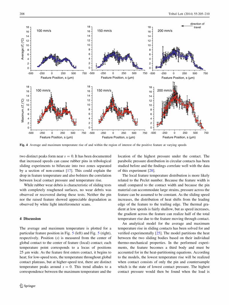
two distinct peaks form near s = 0. It has been documented
that increased speeds can cause rubber pins in tribological
sliding experiments to bifurcate into two zones separated
by a section of non-contact [17]. This could explain the
drop in feature temperature and also bolsters the correlation
between local contact pressure and temperature rise.
While rubber wear debris is characteristic of sliding tests
with completely roughened surfaces, no wear debris was
observed or recovered during these tests. Neither the pin
nor the raised feature showed appreciable degradation as
observed by white light interferometer scans.
4 Discussion
The average and maximum temperature is plotted for a
particular feature position in Fig. 5 (left) and Fig. 5 (right),
respectively. Position (s) is measured from the center of
global contact to the center of feature (local) contact; each
temperature point corresponds to a locus of positions
25 lm wide. As the feature first enters contact, it begins to
heat; for low-speed tests, the temperature throughout global
contact plateaus, but at higher-speed test, there are distinct
temperature peaks around s = 0. This trend alludes to a
correspondence between the maximum temperature and the
location of the highest pressure under the contact. The
parabolic pressure distribution in circular contacts has been
studied before and the findings correlate well with the data
of this experiment [28].
The local feature temperature distribution is more likely
related to the Peclet number. Because the feature width is
small compared to the contact width and because the pin
material can accommodate large strains, pressure across the
feature can be assumed to be constant. As the sliding speed
increases, the distribution of heat shifts from the leading
edge of the feature to the trailing edge. The thermal gra-
dient at low speeds is fairly shallow, but as speed increases,
the gradient across the feature can realize half of the total
temperature rise due to the feature moving through contact.
An analytical model for the average and maximum
temperature rise in sliding contacts has been solved for and
verified experimentally [25]. The model partitions the heat
between the two sliding bodies based on their individual
thermo-mechanical properties. In the performed experi-
ments, the feature becomes a third body and must be
accounted for in the heat-partitioning equations. According
to the models, the lowest temperature rise will be realized
when contact consists of only the pin and countersample
which is the state of lowest contact pressure. The highest
contact pressure would then be found when the load is
0
2
4
6
8
10
12
14
16
18
Ave
rage
)C°(,TΔ
Max
imum
)C°(,TΔ
Feature Position, s (µm)
0
2
4
6
8
10
12
14
16
18
Feature Position, s (µm)
0
2
4
6
8
10
12
14
16
18
Feature Position, s (µm)
0
2
4
6
8
10
12
14
16
18
Feature Position, s (µm)
0
2
4
6
8
10
12
14
16
18
Feature Position, s (µm)
-500 -250 0 250 500 750
0
2
4
6
8
10
12
14
16
18
Feature Position, s (µm)
200 mm/s150 mm/s100 mm/s
200 mm/s150 mm/s100 mm/s
direction oftravel
-500 -250 0 250 500 750 -500 -250 0 250 500 750
-500 -250 0 250 500 750-500 -250 0 250 500 750-500 -250 0 250 500 750
Fig. 4 Average and maximum temperature rise of and within the region of interest of the positive feature at varying speeds
208 Tribol Lett (2014) 55:205–210
123

applied only to the contact area of the feature. Applying
these two conditions to Jaeger’s model provides bounds for
the measured data and are given in Fig. 6.
The analysis process predicts feature position fairly
well; however, the final judgment on feature position lies
with the experimentalist. A small portion of frames exists
in which the feature is obscured and the experimentalist
must decide, based on prior frames and localized heating in
the current frame, where the feature is located. This con-
tributes to the error in Fig. 4.
5 Conclusions
A method to measure the temperature rise due to the input
of heat from a single perturbation into such a system was
developed. This method provides a way to study the effects
of frictional heating on a simple and fundamental level. A
positive, cylindrical SU-8 micro-feature was cured onto a
calcium fluoride countersurface. The rubber pin and mod-
ified countersample were tested in a pin-on-disk configu-
ration, and sliding experiments were conducted at various
sliding speeds.
The feature created an average of 8 �C and maximum of
16 �C temperature rise over the bulk sliding temperature.
Feature temperature rises increased with increasing sliding
speeds. The measured average and maximum feature
temperature was compared to predicted temperature values
predicted by Jaeger’s heating model for sliding contacts.
The predicted average and maximum temperature values
provided lower and upper bounds, respectively, to the
measured data.
Acknowledgments The authors would like to thank Jon Bart Ten
Hove at the University of Florida for his assistance with countersur-
face fabrication. Additionally, the authors would like to thank Dr.
Dylan Morris and Olivier Gerardin for their useful insight and guid-
ance throughout ideation and experimentation. This work was sup-
ported by Michelin North America and could not have been
completed without the help of the Tribology Lab at the University of
Florida.
References
1. Grosch, K.A., Schallamach, A.: Tyre wear at controlled slip.
Wear 4, 356 (1961)
0
2
4
6
8
10
12
14
16
18
Feature Position, s (µm)-500 -250 0 250 500 750-500 -250 0 250 500 750
0
2
4
6
8
10
12
14
16
18
Tem
pera
ture
Ris
e,T
,(°C
)
Feature Position, s (µm)
10 mm/s 25 mm/s 50 mm/s 75 mm/s 100 mm/s 150 mm/s 200 mm/s
Maximum Temperature Rise Average Temperature Rise
Slid
ing
Spe
ed
Slid
ing
Spe
ed
Fig. 5 (Left) Average
temperature rise of positive
feature region of interest as it
moves through global contact.
(Right) Maximum temperature
rise within the positive feature
region of interest as it moves
through global contact. The
position of the 150-lm feature
was determined from the center
of global contact between the
pin and disk
Sliding Speed Avg. Max.(mm/s)
10255075100150200
(ΔT, °C)0.71.42.02.23.34.25.0
(ΔT, °C)1.74.05.65.512.914.216.7
Avg. Max.(ΔT, °C)
4.37.210.010.516.119.122.4
(ΔT, °C)0.81.92.92.85.66.98.0
Predicted Measured
0 50 100 150 2000
2
4
6
8
10
12
14
16
18
20
22
24
Sliding Speed, v (mm/s)
Predicted Maximum ΔTPredicted Average ΔT
Maximum Measured ΔTAvgerage Measured ΔT
Fig. 6 Measured maximum and
average temperature rises for
each sliding speed. Jaeger’s
solution for average and the
modified solution for maximum
temperature rises within contact
provide bounds for the data
Tribol Lett (2014) 55:205–210 209
123

2. Grosch, K.A.: Relation between friction and visco-elastic prop-
erties of rubber. Proc. R. Soc. Lond. A-Math. Phys. Sci.
274(1356), 21 (1963). doi:10.1098/rspa.1963.0112
3. Tabor, D.: The mechanism of rolling friction. II. The elastic
range. Proc. R. Soc. Lond. 229(1177), 198–220 (1955)
4. Lancaster, J.K.: Estimation of the limiting PV relationships for
thermoplastic bearing materials. Tribology 4(2), 82–86 (1971).
doi:10.1016/0041-2678(71)90136-9
5. Barquins, M.: Rubber friction variation with rate and tempera-
ture: some new observations. Physics 19, 547–563 (1985)
6. Siroux, M., Kasem, H., Thevenet, J., Desmet, B., Dufrenoy, P.:
Local temperatures evaluation on the pin–disc interface using
infrared metrology. Int. J. Therm. Sci. 50(4), 486–492 (2011).
doi:10.1016/j.ijthermalsci.2010.11.001
7. Ingram, M., Reddyhoff, T., Spikes, H.A.: Thermal behaviour of a
slipping wet clutch contact. Tribol. Lett. 41(1), 23–32 (2011).
doi:10.1007/s11249-010-9669-2
8. Bos, J., Moes, H.: Frictional heating of tribological contacts.
J. Tribol. 117(1), 171–177 (1995)
9. Bushan, B. (ed.): Modern Tribology Handbook, 1st edn. CRC
Press LLC, Boca Raton (2001)
10. Gulino, R., Bair, S., Winer, W.O., Bhushan, B.: Temperature
measurement of microscopic areas within a simulated head tape
interface using infrared radiometric technique. J. Tribol. Trans.
ASME 108(1), 29–34 (1986)
11. Bair, S., Green, I., Bhushan, B.: Measurement of asperity tem-
peratures of a read write head slider bearing in hard magnetic
recording disks. J. Tribol. Trans. ASME 113(3), 547–554 (1991).
doi:10.1115/1.2920658
12. Santini, J.J., Kennedy Jr, F.E.: An experimental investigation of
surface temperatures and wear in disk brakes. Lubr. Eng. 31(8),
402–417 (1974)
13. Nagaraj, H.S., Sanborn, D.M., Winer, W.O.: Direct surface
temperature measurement by infrared radiation in elastohydro-
dynamic contacts and the correlation with the Blok flash tem-
perature theory. Wear 49(1), 43–59 (1978). doi:10.1016/0043-
1648(78)90022-4
14. Tong, H.M., Arjavalingam, G., Haynes, R.D., Hyer, G.N., Ritsko,
J.J.: High-temperature thin-film Pt–Ir thermocouple with fast time
response. Rev. Sci. Instrum. 58(5), 875–877 (1987). doi:10.1063/
1.1139649
15. Schreck, E., Fontana, R.E., Singh, G.P.: Thin-film thermocouple
sensors for measurement of contact temperature during slider
asperity interaction on magnetic recording disks. IEEE Trans.
Magn. 28(5), 2548–2550 (1992). doi:10.1109/20.179552
16. Kennedy, F.E., Frusescu, D., Li, J.: Thin film thermocouple
arrays for sliding surface temperature measurement. Wear
207(1–2), 46–54 (1997). doi:10.1016/s0043-1648(96)07473-x
17. Rowe, K.G., Bennett, A.I., Krick, B.A., Gregory Sawyer, W.:
In situ thermal measurements of sliding contacts. Tribol Int 62(0),
208–214 (2013). doi:10.1016/j.triboint.2013.02.028
18. Archard, J.F., Rowntree, R.A.: The temperature of rubbing bod-
ies; part 2, the distribution of temperatures. Wear 128(1), 1–17
(1988). doi:10.1016/0043-1648(88)90249-9
19. Archard, J.F.: The temperature of rubbing surfaces. Wear 2(6),
438–455 (1959). doi:10.1016/0043-1648(59)90159-0
20. Schallamach, A.: How does rubber slide? Wear 17(4), 301–312
(1971)
21. Carslaw, H.S., Jaeger, J.C.: Conduction of Heat in Solids, 2nd
edn. Clarendon Press, Oxford University Press, Oxford
[Oxfordshire], New York (1986)
22. Blok, H.: The dissipation of frictional heat. Appl. Sci. Res. 5(2),
151–181 (1955). doi:10.1007/bf03184615
23. Blok, H.: The flash temperature concept. Wear 6(6), 483–494
(1963). doi:10.1016/0043-1648(63)90283-7
24. Blok, H.: Theoretical study of temperature rise at surfaces of
actual contact under oiliness lubricating conditions. In: Pro-
ceedings of the General Discussion on Lubrication and Lubri-
cants, vol. 2, pp. 222–235 (1937)
25. Jaeger, J.C.: Moving sources of heat and the temperature at
sliding contacts. J. Proc. R. Soc. N. S. W. 76, 203–224 (1942)
26. Kennedy, F.E., Hussaini, S.Z.: Thermo-mechanical analysis of
dry sliding systems. Comput. Struct. 26(1–2), 345–355 (1987).
doi:10.1016/0045-7949(87)90264-1
27. Kennedy, F.: Frictional heating and contact temperatures. In:
Modern Tribology Handbook, Two Volume Set. Mechanics &
Materials Science. CRC Press, Boca Raton (2000)
28. Tian, X.F., Kennedy, F.E.: Maximum and averate flash temper-
atures in sliding contacts. J. Tribol. Trans. ASME 116(1),
167–174 (1994). doi:10.1115/1.2927035
29. Tian, X., Kennedy, F.: Contact surface temperature models for
finite bodies in dry and boundary lubricated sliding. J. Tribol.
115(3), 411–418 (1993)
30. Bansal, D.G., Streator, J.L.: On estimations of maximum and
average interfacial temperature rise in sliding elliptical contacts.
Wear 278–279, 18–27 (2012). doi:10.1016/j.wear.2011.12.006
210 Tribol Lett (2014) 55:205–210
123


![Does shear heating of pore fluid contribute to earthquake ...esag.harvard.edu › rice › 219_SegallRice_shr_ht_JGR06.pdfSleep [1995] considered the role of shear heating and frictional](https://img.pdfslide.net/doc/110x75/60bc578d49991d6d112d8d99/does-shear-heating-of-pore-fluid-contribute-to-earthquake-esag-a-rice-a.jpg)