Embed Size (px)
Citation preview
1
DYNAMIC MODEL OF FULL-SCALE MR DAMPERS FOR CIVIL ENGINEERING APPLICATIONS
G. YANG1, H.J. JUNG2 and B.F. SPENCER, Jr.3
1 Doctoral Candidate, Department of Civil Engineering and Geological Sciences, University of Notre Dame, Notre Dame, IN 46556, USA, [email protected]
2 Postdoctoral Researcher, Department of Civil Engineering and Geological Sciences, University of Notre Dame, Notre Dame, IN 46556, [email protected]
3 Linbeck Professor of Engineering, Department of Civil Engineering and Geological Sciences, University of Notre Dame, Notre Dame, IN 46556, [email protected]
ABSTRACT: Magnetorheological (MR) dampers are one of the most promising newdevices for structural vibration reduction. Because of their mechanical simplicity, highdynamic range, low power requirements, large force capacity, and robustness, thesedevices have been shown to mesh well with application demands and constraints to offeran attractive means of protecting civil infrastructure systems against severe earthquakeand wind loading. Quasi-static models of MR dampers have been investigated by severalresearchers. Although useful for design of the damper, quasi-static models are not suffi-cient to describe the MR damper behavior under dynamic loading. This paper presents anew dynamic model of the overall MR damper system which is comprised of two parts: (i)a dynamic model of the power supply, and (ii) a dynamic model of the MR damper.Because previous studies have demonstrated that a current driven power supply can dra-matically reduce the MR damper response time, this study employs a current driver topower the MR damper. The operating principles of the current driver, and an appropriatedynamic model are provided. Subsequently, MR damper response analysis is performed,and a mechanical model using the Bouc-Wen model is proposed to predict the MR damperbehavior under dynamic loading. This model accommodates MR fluid inertial and shearthinning effects. Experimental verification has shown that the proposed dynamic model ofthe MR damper system predicts the experimental results very well.
Key Words: MR fluids, MR dampers, Smart damping devices, Smart materials, Hysteresis model, Parameter estimation, System identification, Rheological technology
INTRODUCTION
Magnetorheological fluids (or simply “MR” fluids) belong to the class of controllable fluids. The es-sential characteristic of MR fluids is their ability to reversibly change from free-flowing, linear viscousliquids to semi-solids having a controllable yield strength in milliseconds when exposed to a magneticfield. This feature provides simple, quiet, rapid-response interfaces between electronic controls and me-chanical systems. MR fluid dampers are new semi-active devices that utilize MR fluids to provide con-trollable damping forces. These devices overcome many of the expenses and technical difficultiesassociated with semi-active devices previously considered. Recent studies have shown that the semi-ac-tive dampers can achieve the majority of the performance of fully active systems, thus allowing for thepossibility of effective response reduction during both moderate and strong seismic activity (Dyke et al.
2
1996; Jansen & Dyke 2000; Johnson et al. 2001; Spencer et al. 2000). For these reasons, significant ef-forts have been devoted to the development and implementation of MR devices.
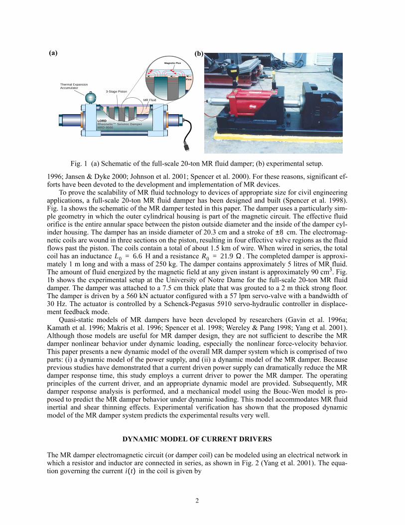
To prove the scalability of MR fluid technology to devices of appropriate size for civil engineeringapplications, a full-scale 20-ton MR fluid damper has been designed and built (Spencer et al. 1998).Fig. 1a shows the schematic of the MR damper tested in this paper. The damper uses a particularly sim-ple geometry in which the outer cylindrical housing is part of the magnetic circuit. The effective fluidorifice is the entire annular space between the piston outside diameter and the inside of the damper cyl-inder housing. The damper has an inside diameter of 20.3 cm and a stroke of cm. The electromag-netic coils are wound in three sections on the piston, resulting in four effective valve regions as the fluidflows past the piston. The coils contain a total of about 1.5 km of wire. When wired in series, the totalcoil has an inductance H and a resistance . The completed damper is approxi-mately 1 m long and with a mass of 250 kg. The damper contains approximately 5 litres of MR fluid.The amount of fluid energized by the magnetic field at any given instant is approximately 90 cm3. Fig.1b shows the experimental setup at the University of Notre Dame for the full-scale 20-ton MR fluiddamper. The damper was attached to a 7.5 cm thick plate that was grouted to a 2 m thick strong floor.The damper is driven by a 560 kN actuator configured with a 57 lpm servo-valve with a bandwidth of30 Hz. The actuator is controlled by a Schenck-Pegasus 5910 servo-hydraulic controller in displace-ment feedback mode.
Quasi-static models of MR dampers have been developed by researchers (Gavin et al. 1996a;Kamath et al. 1996; Makris et al. 1996; Spencer et al. 1998; Wereley & Pang 1998; Yang et al. 2001).Although those models are useful for MR damper design, they are not sufficient to describe the MRdamper nonlinear behavior under dynamic loading, especially the nonlinear force-velocity behavior.This paper presents a new dynamic model of the overall MR damper system which is comprised of twoparts: (i) a dynamic model of the power supply, and (ii) a dynamic model of the MR damper. Becauseprevious studies have demonstrated that a current driven power supply can dramatically reduce the MRdamper response time, this study employs a current driver to power the MR damper. The operatingprinciples of the current driver, and an appropriate dynamic model are provided. Subsequently, MRdamper response analysis is performed, and a mechanical model using the Bouc-Wen model is pro-posed to predict the MR damper behavior under dynamic loading. This model accommodates MR fluidinertial and shear thinning effects. Experimental verification has shown that the proposed dynamicmodel of the MR damper system predicts the experimental results very well.
DYNAMIC MODEL OF CURRENT DRIVERS
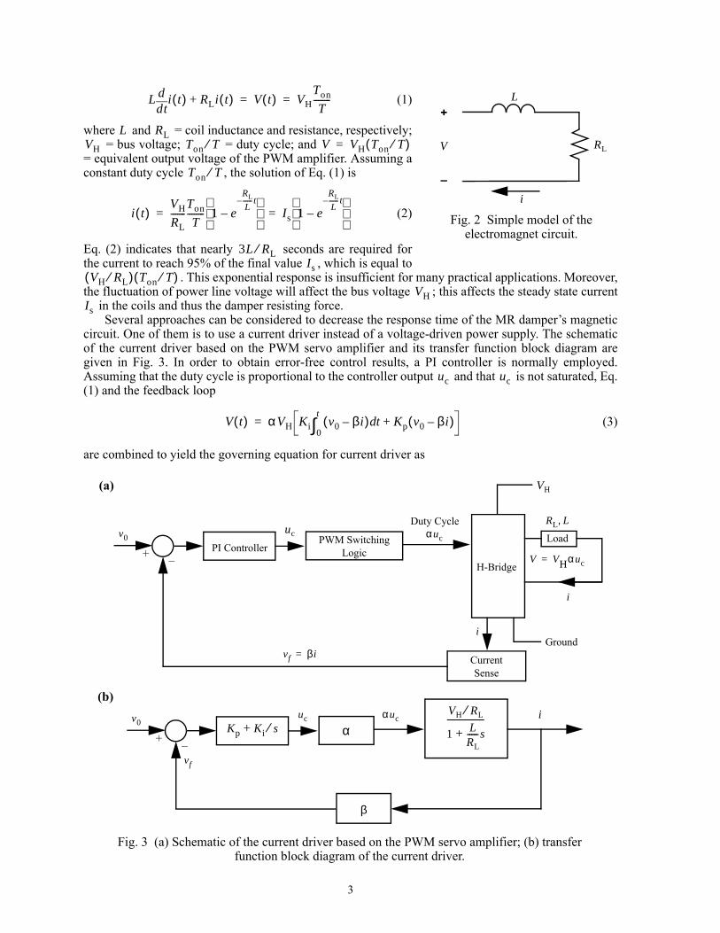
The MR damper electromagnetic circuit (or damper coil) can be modeled using an electrical network inwhich a resistor and inductor are connected in series, as shown in Fig. 2 (Yang et al. 2001). The equa-tion governing the current in the coil is given by
Piston Motion
Magnetic Flux
Flow
MR Fluid
Thermal Expansion Accumulator
3-Stage Piston
LORDRheonetic™ Seismic DamperMRD-9000
Fig. 1 (a) Schematic of the full-scale 20-ton MR fluid damper; (b) experimental setup.
(b)(a)
8±
L0 6.6= R0 21.9 Ω=
i t( )
3
(1)
where and = coil inductance and resistance, respectively; = bus voltage; = duty cycle; and
= equivalent output voltage of the PWM amplifier. Assuming aconstant duty cycle , the solution of Eq. (1) is
(2)
Eq. (2) indicates that nearly seconds are required forthe current to reach 95% of the final value , which is equal to
. This exponential response is insufficient for many practical applications. Moreover,the fluctuation of power line voltage will affect the bus voltage ; this affects the steady state current
in the coils and thus the damper resisting force.Several approaches can be considered to decrease the response time of the MR damper’s magnetic
circuit. One of them is to use a current driver instead of a voltage-driven power supply. The schematicof the current driver based on the PWM servo amplifier and its transfer function block diagram aregiven in Fig. 3. In order to obtain error-free control results, a PI controller is normally employed.Assuming that the duty cycle is proportional to the controller output and that is not saturated, Eq.(1) and the feedback loop
(3)
are combined to yield the governing equation for current driver as
Fig. 2 Simple model of the electromagnet circuit.
+
–
V RL
L
i
Ltd
d i t( ) RLi t( )+ V t( ) VHTon
T--------= =
L RLVH Ton T⁄ V VH Ton T⁄( )=
Ton T⁄
i t( )VH
RL-------
Ton
T-------- 1 e
RL
L------ t–
–
Is 1 e
RL
L------ t–
–
= =
3L RL⁄Is
VH RL⁄( ) Ton T⁄( )VH
Is
+ PI ControllerPWM Switching
LogicH-Bridge
VH
i
Load
Ground
CurrentSense
–
Fig. 3 (a) Schematic of the current driver based on the PWM servo amplifier; (b) transfer function block diagram of the current driver.
v0
i
vf βi=
uc
Duty Cycleαuc
RL L,
V VHαuc=
(a)
+ –
v0
vf
uc αucKp Ki s⁄+ α
β
VH RL⁄
1 LRL
-----s+-----------------
(b)i
uc uc
V t( ) αVH Ki v0 βi–( ) t Kp v0 βi–( )+d0
t
∫=
4
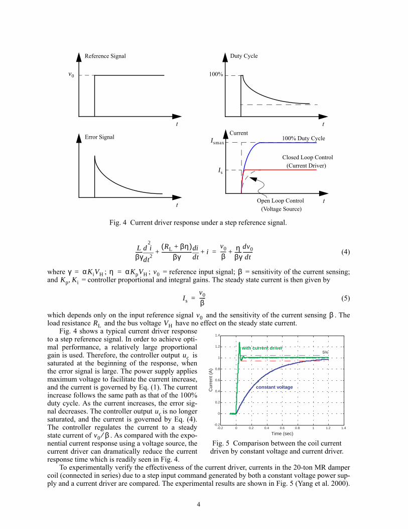
(4)
where ; ; = reference input signal; = sensitivity of the current sensing;and = controller proportional and integral gains. The steady state current is then given by
(5)
which depends only on the input reference signal and the sensitivity of the current sensing . Theload resistance and the bus voltage have no effect on the steady state current.
Fig. 4 shows a typical current driver responseto a step reference signal. In order to achieve opti-mal performance, a relatively large proportionalgain is used. Therefore, the controller output issaturated at the beginning of the response, whenthe error signal is large. The power supply appliesmaximum voltage to facilitate the current increase,and the current is governed by Eq. (1). The currentincrease follows the same path as that of the 100%duty cycle. As the current increases, the error sig-nal decreases. The controller output is no longersaturated, and the current is governed by Eq. (4).The controller regulates the current to a steadystate current of . As compared with the expo-nential current response using a voltage source, thecurrent driver can dramatically reduce the currentresponse time which is readily seen in Fig. 4.
To experimentally verify the effectiveness of the current driver, currents in the 20-ton MR dampercoil (connected in series) due to a step input command generated by both a constant voltage power sup-ply and a current driver are compared. The experimental results are shown in Fig. 5 (Yang et al. 2000).
Lβγ------
t2
2
d
d i RL βη+( )βγ
-------------------------td
di i+ +v0
β----- η
βγ------
dv0
dt--------+=
γ αKiVH= η α KpVH= v0 βKp Ki,
Is
v0
β-----=
v0 βRL VH
Fig. 5 Comparison between the coil current driven by constant voltage and current driver.
-0.2 0 0.2 0.4 0.6 0.8 1 1.2 1.4-0.2
0
0.2
0.4
0.6
0.8
1
1.2
1.4
5%
Time (sec)
constant voltage
with current driver
Cur
rent
(A
)
Duty Cycle
t
100%
t
v0
Reference Signal
t
Error Signal
t
CurrentIsmax
100% Duty Cycle
Is(Current Driver)
Closed Loop Control
(Voltage Source)Open Loop Control
Fig. 4 Current driver response under a step reference signal.
uc
uc
v0 β⁄
5
The constant voltage case corresponds to the scenario where a voltage-driven power supply is attachedto the damper coils. The time constant for the coils of the 20-ton MR damper arranged in seriesis 0.3 sec. Therefore, as shown in Fig. 5, it takes about 1 sec for the current to achieve 95% of the finalvalue, indicating that the damper has only a 1 Hz bandwidth. Alternatively, using a current driver, the5% error range is achieved within 0.06 sec. The current driver includes a DC power supply (±120 V)and a PWM servo amplifier manufactured by Advanced Motion Controls operating under the currentmode. Because the current driver clearly offers substantial reductions in the response time, the subse-quent results reported in this paper will employ this current driver.
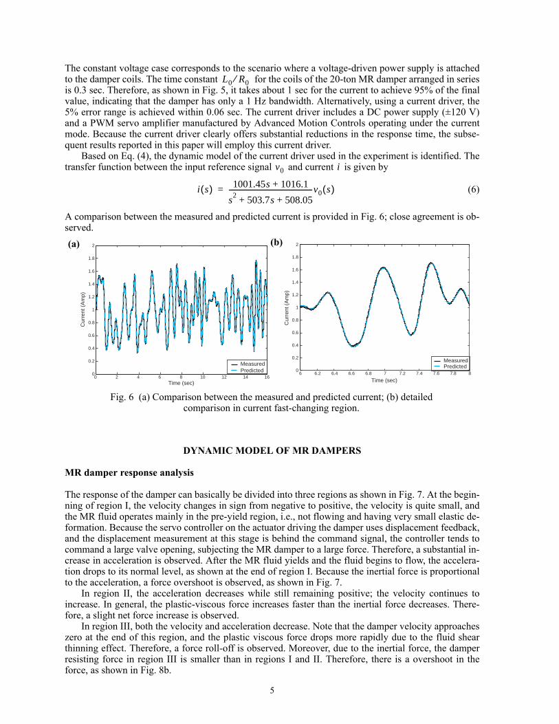
Based on Eq. (4), the dynamic model of the current driver used in the experiment is identified. Thetransfer function between the input reference signal and current is given by
(6)
A comparison between the measured and predicted current is provided in Fig. 6; close agreement is ob-served.
DYNAMIC MODEL OF MR DAMPERS
MR damper response analysis
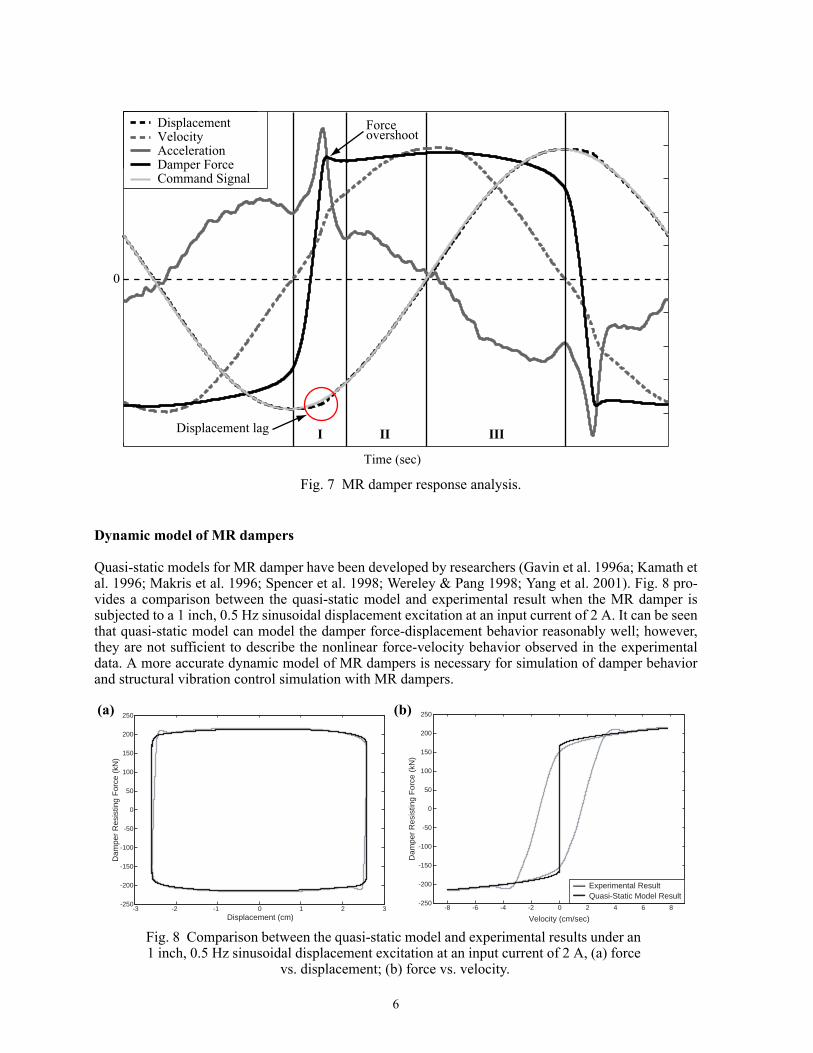
The response of the damper can basically be divided into three regions as shown in Fig. 7. At the begin-ning of region I, the velocity changes in sign from negative to positive, the velocity is quite small, andthe MR fluid operates mainly in the pre-yield region, i.e., not flowing and having very small elastic de-formation. Because the servo controller on the actuator driving the damper uses displacement feedback,and the displacement measurement at this stage is behind the command signal, the controller tends tocommand a large valve opening, subjecting the MR damper to a large force. Therefore, a substantial in-crease in acceleration is observed. After the MR fluid yields and the fluid begins to flow, the accelera-tion drops to its normal level, as shown at the end of region I. Because the inertial force is proportionalto the acceleration, a force overshoot is observed, as shown in Fig. 7.
In region II, the acceleration decreases while still remaining positive; the velocity continues toincrease. In general, the plastic-viscous force increases faster than the inertial force decreases. There-fore, a slight net force increase is observed.
In region III, both the velocity and acceleration decrease. Note that the damper velocity approacheszero at the end of this region, and the plastic viscous force drops more rapidly due to the fluid shearthinning effect. Therefore, a force roll-off is observed. Moreover, due to the inertial force, the damperresisting force in region III is smaller than in regions I and II. Therefore, there is a overshoot in theforce, as shown in Fig. 8b.
L0 R0⁄
v0 i
i s( ) 1001.45s 1016.1+
s2 503.7s 508.05+ +
--------------------------------------------------v0 s( )=
0 2 4 6 8 10 12 14 160
0.2
0.4
0.6
0.8
1
1.2
1.4
1.6
1.8
2
Time (sec)
Cur
rent
(A
mp)
MeasuredPredicted 6 6.2 6.4 6.6 6.8 7 7.2 7.4 7.6 7.8 8
0
0.2
0.4
0.6
0.8
1
1.2
1.4
1.6
1.8
2
Time (sec)
Cur
rent
(A
mp)
MeasuredPredicted
Fig. 6 (a) Comparison between the measured and predicted current; (b) detailed comparison in current fast-changing region.
(a) (b)
6
Dynamic model of MR dampers
Quasi-static models for MR damper have been developed by researchers (Gavin et al. 1996a; Kamath etal. 1996; Makris et al. 1996; Spencer et al. 1998; Wereley & Pang 1998; Yang et al. 2001). Fig. 8 pro-vides a comparison between the quasi-static model and experimental result when the MR damper issubjected to a 1 inch, 0.5 Hz sinusoidal displacement excitation at an input current of 2 A. It can be seenthat quasi-static model can model the damper force-displacement behavior reasonably well; however,they are not sufficient to describe the nonlinear force-velocity behavior observed in the experimentaldata. A more accurate dynamic model of MR dampers is necessary for simulation of damper behaviorand structural vibration control simulation with MR dampers.
Fig. 7 MR damper response analysis.
0
DisplacementVelocityAccelerationDamper ForceCommand Signal
I II III
Time (sec)
Displacement lag
Forceovershoot
-3 -2 -1 0 1 2 3-250
-200
-150
-100
-50
0
50
100
150
200
250
Displacement (cm)
Dam
per
Res
istin
g F
orce
(kN
)
-8 -6 -4 -2 0 2 4 6 8-250
-200
-150
-100
-50
0
50
100
150
200
250
Velocity (cm/sec)
Dam
per
Res
istin
g F
orce
(kN
)
Experimental ResultQuasi-Static Model Result
(b)(a)
Fig. 8 Comparison between the quasi-static model and experimental results under an 1 inch, 0.5 Hz sinusoidal displacement excitation at an input current of 2 A, (a) force
vs. displacement; (b) force vs. velocity.
7
Two types of dynamic models of controllable fluid damper have been investigated by researchers:non-parametric and parametric models. Ehrgott & Masri (1992) and Gavin et al. (1996b) presented anon-parametric approach employing orthogonal Chebychev polynomials to predict the damper resistingforce using the damper displacement and velocity information. Chang & Roschke (1998) developed aneural network model to emulate the dynamic behavior of MR dampers. However, the non-parametricdamper models are often quite complicated. Gamato & Filisko (1991) proposed a parametric viscoelas-tic-plastic model based on the Bingham model. Wereley et al. (1998) developed a nonlinear hystereticbiviscous model, which is an extension of the nonlinear biviscous model having an improved represen-tation of the pre-yield hysteresis. Spencer et al. (1997) proposed a mechanical model based on theBouc-Wen model. This model can well capture the force roll-off in the low velocity region due to bleedor blow-by of fluid between the piston and cylinder. Nevertheless, all parametric models mentionedabove are not considered the fluid inertial effect and shear thinning effect especially in the low velocityregion.
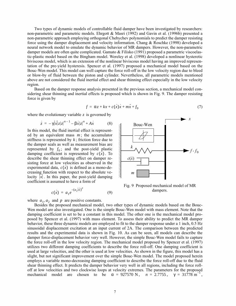
Based on the damper response analysis presented in the previous section, a mechanical model con-sidering shear thinning and inertial effects is proposed which is shown in Fig. 9. The damper resistingforce is given by
(7)
where the evolutionary variable is governed by
(8)
In this model, the fluid inertial effect is represent-ed by an equivalent mass ; the accumulatorstiffness is represented by ; friction force due tothe damper seals as well as measurement bias arerepresented by ; and the post-yield plasticdamping coefficient is represented by . Todescribe the shear thinning effect on damper re-sisting force at low velocities as observed in theexperimental data, is defined as a mono-de-creasing function with respect to the absolute ve-locity . In this paper, the post-yield dampingcoefficient is assumed to have a form of
(9)
where and are positive constants.Besides the proposed mechanical model, two other types of dynamic models based on the Bouc-
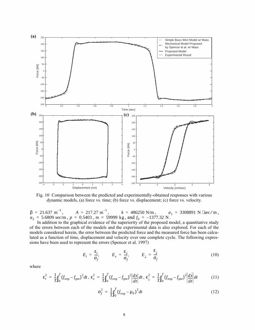
Wen model are also investigated. One is the simple Bouc-Wen model with mass element. Note that thedamping coefficient is set to be a constant in this model. The other one is the mechanical model pro-posed by Spencer et al. (1997) with mass element. To assess their ability to predict the MR damperbehavior, these three dynamic models are employed to fit to the damper response under a 1 inch, 0.5 Hzsinusoidal displacement excitation at an input current of 2A. The comparison between the predictedresults and the experimental data is shown in Fig. 10. As can be seen, all models can describe thedamper force-displacement behavior very well. However, the simple Bouc-Wen model fails to capturethe force roll-off in the low velocity region. The mechanical model proposed by Spencer et al. (1997)utilizes two different damping coefficients to describe the force roll-off. One damping coefficient isused at large velocities, and the other is used at low velocities. As shown in the figure, this model has aslight, but not significant improvement over the simple Bouc-Wen model. The model proposed hereinemploys a variable mono-decreasing damping coefficient to describe the force roll-off due to the fluidshear thinning effect. It predicts the damper behavior very well in all regions, including the force roll-off at low velocities and two clockwise loops at velocity extremes. The parameters for the proposedmechanical model are chosen to be , , ,
f αz kx c x·( )x· mx·· f0+ + + +=
c(x)
k
Bouc-Wenx
f - f0
m
.
Fig. 9 Proposed mechanical model of MR dampers.
z
z· γ x· z zn 1–– βx· z
n– Ax·+=
mk
f0c x·( )
c x·( )
x·
c x·( ) a1ea2 x·( )
p–
=
a1 a2, p
α 927570 N= n 2.7755= γ 31778 m 1–=
8
, , , ,, , , and .
In addition to the graphical evidence of the superiority of the proposed model, a quantitative studyof the errors between each of the models and the experimental data is also explored. For each of themodels considered herein, the error between the predicted force and the measured force has been calcu-lated as a function of time, displacement and velocity over one complete cycle. The following expres-sions have been used to represent the errors (Spencer et al. 1997)
(10)
where
, , (11)
(12)
0 0.2 0.4 0.6 0.8 1 1.2 1.4 1.6 1.8 2-250
-200
-150
-100
-50
0
50
100
150
200
250
Time (sec)
For
ce (
kN)
Experimental Result
Simple Bouc-Wen Model w/ MassMechanical Model Proposed by Spencer et al. w/ MassProposed Model
-4 -3 -2 -1 0 1 2 3 4-250
-200
-150
-100
-50
0
50
100
150
200
250
Displacement (cm)
For
ce (
kN)
-8 -4 0 4 8-250
-200
-150
-100
-50
0
50
100
150
200
250
Velocity (cm/sec)
For
ce (
kN)
Fig. 10 Comparison between the predicted and experimentally-obtained responses with various dynamic models, (a) force vs. time; (b) force vs. displacement; (c) force vs. velocity.
(a)
(b) (c)
β 21.637 m 1–= A 217.27 m 1–= k 486250 N/m= a1 3308891 N sec m⁄⋅=a2 5.6809 sec/m= p 0.5403= m 59999 kg= f0 1377.32– N=
Et
εt
σf
----- Ex,εx
σf
----- Ex·,
εx·
σf
-----= = =
εt2 1
T--- fexp fpre–( )2
td0
T
∫= εx2 1
T--- fexp fpre–( )2 dx
dt------ td
0
T
∫= εx·2 1
T--- fexp fpre–( )2 dx·
dt------ td
0
T
∫=
σf2 1
T--- fexp µF–( )2
td0
T
∫=
9
The resulting error norms are given in Table 1. In all cases, the error norms calculated for the proposedmechanical model are smaller than those calculated for the other models considered, indicating that theproposed model is superior to the other models for the full-scale MR damper under investigation.
Generalization for fluctuating current
All of the data examined previously has been based on the response of the MR damper when the ap-plied current, and hence the magnetic field, was held at a constant level. However, optimal performanceof a control system using this device is expected to be achieved when the magnetic field is continuouslyvaried based on the measured response of the system to which it is attached. To use the damper in thisway, a model must be developed which is capable of predicting the behavior of the MR damper for afluctuating current.
To determine a model which is valid under the fluctuating input current, the functional dependenceof the parameters on the input current must be determined. Since the fluid yield stress is dependent oninput current, can then be assumed as a function of the input current . Moreover, from the experi-ment results, , , , , and are also functions of the input current.
In order to obtain the relationship between the input current and damper parameters , , ,, and , the damper was driven by band-limited random displacement excitations with a cutoff
frequency of 2 Hz at various constant current levels. A constrained nonlinear least-squares optimizationscheme based on the trust-region and preconditioned conjugated gradients (PCG) methods is then used.The results are shown in Table 1. A linear piecewise interpolation approach is utilized to estimate thesedamper parameters for current levels which are not listed in the above table. The rest damper parame-ters which are not varied with input current are chosen to be , ,
, , and .
Note that a first order filter needs to be used to accommodate the dynamics involved in the MR fluidreaching rheological equilibrium
(13)
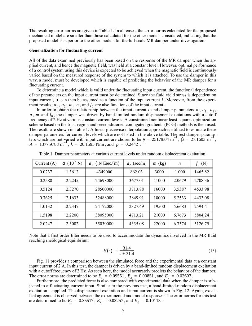
Fig. 11 provides a comparison between the simulated force and the experimental data at a constantinput current of 2 A. In this test, the damper is driven by a band-limited random displacement excitationwith a cutoff frequency of 2 Hz. As seen here, the model accurately predicts the behavior of the damper.The error norms are determined to be , , and .
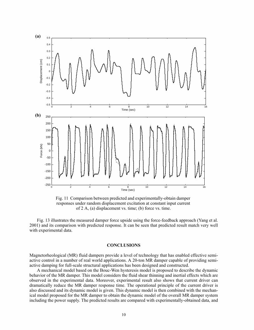
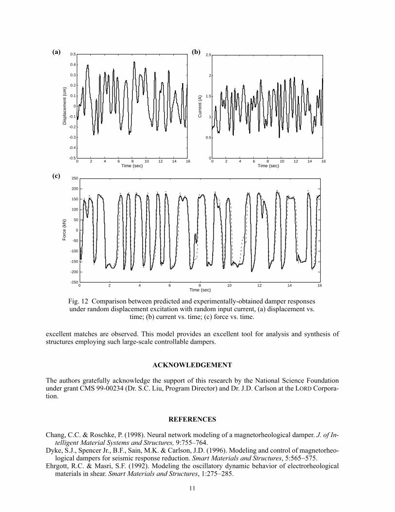
Furthermore, the predicted force is also compared with experimental data when the damper is sub-jected to a fluctuating current input. Similar to the previous test, a band-limited random displacementexcitation is applied. The displacement excitation and input current is shown in Fig. 12. Again, excel-lent agreement is observed between the experimental and model responses. The error norms for this testare determined to be , , and .
Table 1. Damper parameters at various current levels under random displacement excitation.
Current (A) ( N) (sec/m) (kg) (N)
0.0237 1.3612 4349000 862.03 3000 1.000 1465.82
0.2588 2.2245 24698000 3677.01 11000 2.0679 2708.36
0.5124 2.3270 28500000 3713.88 16000 3.5387 4533.98
0.7625 2.1633 32488000 3849.91 18000 5.2533 4433.08
1.0132 2.2347 24172000 2327.49 19500 5.6683 2594.41
1.5198 2.2200 38095000 4713.21 21000 6.7673 5804.24
2.0247 2.3002 35030000 4335.08 22000 6.7374 5126.79
α ia1 a2 m n f0
i α a1 a2n m f0
γ 25179.04 m 1–= β 27.1603 m 1–=A 1377.9788 m 1–= k 20.1595 N/m= p 0.2442=
α 105a1 N sec m⁄⋅( ) a2 m n f0
H s( ) 31.4s 31.4+-------------------=
Et 0.09551= Ex 0.00851= Ex· 0.02607=
Et 0.35517= Ex 0.03257= Ex· 0.10118=
10
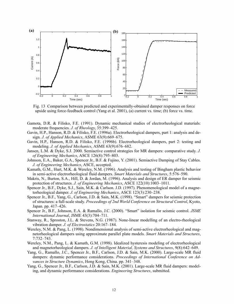
Fig. 13 illustrates the measured damper force upside using the force-feedback approach (Yang et al.2001) and its comparison with predicted response. It can be seen that predicted result match very wellwith experimental data.
CONCLUSIONS
Magnetorheological (MR) fluid dampers provide a level of technology that has enabled effective semi-active control in a number of real world applications. A 20-ton MR damper capable of providing semi-active damping for full-scale structural applications has been designed and constructed.
A mechanical model based on the Bouc-Wen hysteresis model is proposed to describe the dynamicbehavior of the MR damper. This model considers the fluid shear thinning and inertial effects which areobserved in the experimental data. Moreover, experimental result also shows that current driver candramatically reduce the MR damper response time. The operational principle of the current driver isalso discussed and its dynamic model is given. This dynamic model is then combined with the mechan-ical model proposed for the MR damper to obtain the dynamic model of the overall MR damper systemincluding the power supply. The predicted results are compared with experimentally-obtained data, and
0 2 4 6 8 10 12 14 16-0.5
-0.4
-0.3
-0.2
-0.1
0
0.1
0.2
0.3
0.4
0.5
Time (sec)
Dis
plac
emen
t (cm
)
0 2 4 6 8 10 12 14 16-250
-200
-150
-100
-50
0
50
100
150
200
250
Time (sec)
For
ce (
kN)
Fig. 11 Comparison between predicted and experimentally-obtain damper responses under random displacement excitation at constant input current
of 2 A, (a) displacement vs. time; (b) force vs. time.
(a)
(b)
11
excellent matches are observed. This model provides an excellent tool for analysis and synthesis ofstructures employing such large-scale controllable dampers.
ACKNOWLEDGEMENT
The authors gratefully acknowledge the support of this research by the National Science Foundationunder grant CMS 99-00234 (Dr. S.C. Liu, Program Director) and Dr. J.D. Carlson at the LORD Corpora-tion.
REFERENCES
Chang, C.C. & Roschke, P. (1998). Neural network modeling of a magnetorheological damper. J. of In-telligent Material Systems and Structures, 9:755–764.
Dyke, S.J., Spencer Jr., B.F., Sain, M.K. & Carlson, J.D. (1996). Modeling and control of magnetorheo-logical dampers for seismic response reduction. Smart Materials and Structures, 5:565–575.
Ehrgott, R.C. & Masri, S.F. (1992). Modeling the oscillatory dynamic behavior of electrorheologicalmaterials in shear. Smart Materials and Structures, 1:275–285.
0 2 4 6 8 10 12 14 16-0.5
-0.4
-0.3
-0.2
-0.1
0
0.1
0.2
0.3
0.4
0.5
Time (sec)
Dis
plac
emen
t (cm
)
0 2 4 6 8 10 12 14 160
0.5
1
1.5
2
2.5
Time (sec)
Cur
rent
(A
)
Fig. 12 Comparison between predicted and experimentally-obtained damper responses under random displacement excitation with random input current, (a) displacement vs.
time; (b) current vs. time; (c) force vs. time.
0 2 4 6 8 10 12 14 16-250
-200
-150
-100
-50
0
50
100
150
200
250
Time (sec)
For
ce (
kN)
(a)
(c)
(b)
12
Gamota, D.R. & Filisko, F.E. (1991). Dynamic mechanical studies of electrorheological materials:moderate frequencies. J. of Rheology, 35:399–425.
Gavin, H.P., Hanson, R.D. & Filisko, F.E. (1996a). Electrorheological dampers, part 1: analysis and de-sign. J. of Applied Mechanics, ASME 63(9):669–675.
Gavin, H.P., Hanson, R.D. & Filisko, F.E. (1996b). Electrorheological dampers, part 2: testing andmodeling. J. of Applied Mechanics, ASME 63(9):676–682.
Jansen, L.M. & Dyke, S.J. 2000. Semiactive control strategies for MR dampers: comparative study. J.of Engineering Mechanics, ASCE 126(8):795–803.
Johnson, E.A., Baker, G.A., Spencer Jr., B.F. & Fujino, Y. (2001). Semiactive Damping of Stay Cables.J. of Engineering Mechanics, ASCE, accepted.
Kamath, G.M., Hurt, M.K. & Wereley, N.M. (1996). Analysis and testing of Bingham plastic behaviorin semi-active electrorheological fluid dampers. Smart Materials and Structures, 5:576–590.
Makris, N., Burton, S.A., Hill, D. & Jordan, M. (1996). Analysis and design of ER damper for seismicprotection of structures. J. of Engineering Mechanics, ASCE 122(10):1003–1011.
Spencer Jr., B.F., Dyke, S.J., Sain, M.K. & Carlson. J.D. (1997). Phenomenological model of a magne-torheological damper. J. of Engineering Mechanics, ASCE 123(3):230–238.
Spencer Jr., B.F., Yang, G., Carlson, J.D. & Sain, M.K. (1998). “Smart” dampers for seismic protectionof structures: a full-scale study. Proceedings of 2nd World Conference on Structural Control, Kyoto,Japan. pp. 417–426.
Spencer Jr., B.F., Johnson, E.A. & Ramallo, J.C. (2000). “Smart” isolation for seismic control. JSMEInternational Journal, JSME 43(3):704–711.
Stanway, R., Sproston, J.L. & Stevens, N.G. (1987). None-linear modelling of an electro-rheologicalvibration damper. J. of Electrostatics 20:167–184.
Wereley, N.M. & Pang, L. (1998). Nondimensional analysis of semi-active electrorheological and mag-netorheological dampers using approximate parallel plate models. Smart Materials and Structures,7:732–743.
Wereley, N.M., Pang, L. & Kamath, G.M. (1998). Idealized hysteresis modeling of electrorheologicaland magnetorheological dampers. J. of Intelligent Material, Systems and Structures, 9(8):642–649.
Yang, G., Ramallo, J.C., Spencer Jr., B.F., Carlson, J.D. & Sain, M.K. (2000). Large-scale MR fluiddampers: dynamic performance considerations. Proceedings of International Conference on Ad-vances in Structure Dynamics, Hong Kong, China. pp. 341–348.
Yang, G., Spencer Jr., B.F., Carlson, J.D. & Sain, M.K. (2001). Large-scale MR fluid dampers: model-ing, and dynamic performance considerations. Engineering Structures, submitted.
-0.2 0 0.2 0.4 0.6 0.8 1-0.2
0
0.2
0.4
0.6
0.8
1
1.2
Time (sec)
Cur
rent
(A
)
-0.2 0 0.2 0.4 0.6 0.8 10
20
40
60
80
100
120
140
160
180
Time (sec)
For
ce (
kN)
MeasuredPredicted
Fig. 13 Comparison between predicted and experimentally-obtained damper responses on force upside using force-feedback control (Yang et al. 2001), (a) current vs. time; (b) force vs. time.
(a) (b)