Embed Size (px)
Citation preview

Dynamic Multipoint VPN
The Dynamic Multipoint VPN feature allows users to better scale large and small IP Security (IPsec) VirtualPrivate Networks (VPNs) by combining generic routing encapsulation (GRE) tunnels, IPsec encryption, andNext Hop Resolution Protocol (NHRP).
Security threats, as well as the cryptographic technologies to help protect against them, are constantly changing.For more information about the latest Cisco cryptographic recommendations, see the Next GenerationEncryption (NGE) white paper.
Note
• Prerequisites for Dynamic Multipoint VPN, on page 1• Restrictions for Dynamic Multipoint VPN, on page 1• Information About Dynamic Multipoint VPN, on page 3• How to Configure Dynamic Multipoint VPN, on page 8• Configuration Examples for Dynamic Multipoint VPN Feature, on page 28• Additional References for Dynamic Multipoint VPN, on page 42• Feature Information for Dynamic Multipoint VPN, on page 42• Glossary, on page 43
Prerequisites for Dynamic Multipoint VPN• Before a multipoint GRE (mGRE) and IPsec tunnel can be established, you must define an Internet KeyExchange (IKE) policy by using the crypto isakmp policy command.
• To use the 2547oDMPVN--Traffic Segmentation Within DMVPN feature you must configureMultiprotocol Label Switching (MPLS) by using thempls ip command.
Restrictions for Dynamic Multipoint VPN• Bidirectional protocol-independent mulitcast (PIM) is not supported over DMVPN. Therefore, you mustuse PIM Sparse mode (ASM) over DMVPN.
• If you use the benefit of this feature, you must use IKE certificates or wildcard preshared keys for InternetSecurity Association Key Management Protocol (ISAKMP) authentication.
Dynamic Multipoint VPN1
It is highly recommended that you do not use wildcard preshared keys becausean attacker will have access to the VPN if one spoke router is compromised.
Note
• GRE tunnel keepalives (that is, the keepalive command under a GRE interface) are not supported onpoint-to-point or multipoint GRE tunnels in a DMVPN network.
• If one spoke is behind one Network Address Translation (NAT) device and a different spoke is behindanother NAT device, and Port Address Translation (PAT) is the type of NAT used on both NAT devices,then a session initiated between the two spokes cannot be established.
One example of a PAT configuration on a NAT interface is:
ip nat inside source list nat_acl interface FastEthernet0/0/1 overload
• When using OSPF point-to-multipoint, you must block the OSPF /32 routes. Add the following on allhub and spoke routers to block these host routes:
router ospf <#>...distribute-list prefix-list Block-32 out //block OSPF/32 connected routes//ip prefix-list Block-32 deny <tunnel-subnet> <mask> ge 32ip prefix-list Block-32 permit any le 32
SSO Restrictions
• The Cisco ASR 1000 Series Routers support stateful IPSec sessions on Embedded Services Processor(ESP) switchover. During ESP switchover, all IPSec sessions will stay up and no user intervention isneeded to maintain IPSec sessions.
• For an ESP reload (no standby ESP), the SA sequence number restarts from 0. The peer router dropspackets that do not have the expected sequence number. You may need to explicitly reestablish IPSecsessions to work around this issue for systems that have a single ESP after an ESP reload. Traffic disruptionmight happen over the IPSec sessions in such cases for the duration of the reload.
• The Cisco ASR 1000 Series Router currently does not support Stateful Switchover (SSO) IPSec sessionson Route Processors (RPs). The IPSec sessions will go down on initiation of the switchover, but willcome back up when the new RP becomes active. No user intervention is needed. Traffic disruption mighthappen over the IPSec sessions for the duration of the switchover, until the sessions are back up.
• The Cisco ASR 1000 Series Router does not support stateful ISSU for IPSec sessions. Before performingan ISSU, you must explicitly terminate all existing IPSec sessions or tunnels prior to the operation andreestablish them post ISSU. Specifically, ensure that there are no half-open or half-established IPSectunnels present before performing ISSU. To do this, we recommend a interface shutdown in the case ofinterfaces that may initiate a tunnel setup, such as a routing protocol initiating a tunnel setup, or interfacesthat have keepalive enabled, or where there is an auto trigger for an IPSec session. Traffic disruptionover the IPSec sessions during ISSU is obvious in this case.
Dynamic Multipoint VPN2
Dynamic Multipoint VPNRestrictions for Dynamic Multipoint VPN
Information About Dynamic Multipoint VPN
Benefits of Dynamic Multipoint VPN
Hub Router Configuration Reduction
• For each spoke router, there is a separate block of configuration lines on the hub router that define thecrypto map characteristics, the crypto access list, and the GRE tunnel interface. This feature allows usersto configure a single mGRE tunnel interface, a single IPsec profile, and no crypto access lists on the hubrouter to handle all spoke routers. Thus, the size of the configuration on the hub router remains constanteven if spoke routers are added to the network.
• DMVPN architecture can group many spokes into a single multipoint GRE interface, removing the needfor a distinct physical or logical interface for each spoke in a native IPsec installation.
Automatic IPsec Encryption Initiation
• GRE has the peer source and destination address configured or resolved with NHRP. Thus, this featureallows IPsec to be immediately triggered for the point-to-point GRE tunneling or when the GRE peeraddress is resolved via NHRP for the multipoint GRE tunnel.
Support for Dynamically Addressed Spoke Routers
• When using point-to-point GRE and IPsec hub-and-spoke VPN networks, the physical interface IPaddress of the spoke routers must be known when configuring the hub router because the IP address mustbe configured as the GRE tunnel destination address. This feature allows spoke routers to have dynamicphysical interface IP addresses (common for cable and DSL connections). When the spoke router comesonline, it will send registration packets to the hub router: within these registration packets is the currentphysical interface IP address of this spoke.
Dynamic Creation for Spoke-to-Spoke Tunnels
• This feature eliminates the need for spoke-to-spoke configuration for direct tunnels. When a spoke routerwants to transmit a packet to another spoke router, it can now use NHRP to dynamically determine therequired destination address of the target spoke router. (The hub router acts as the NHRP server, handlingthe request for the source spoke router.) The two spoke routers dynamically create an IPsec tunnel betweenthem so data can be directly transferred.
Feature Design of Dynamic Multipoint VPNThe DynamicMultipoint VPN feature combines GRE tunnels, IPsec encryption, and NHRP routing to provideusers an ease of configuration via crypto profiles--which override the requirement for defining static cryptomaps--and dynamic discovery of tunnel endpoints.
This feature relies on the following two Cisco enhanced standard technologies:
• NHRP--A client and server protocol where the hub is the server and the spokes are the clients. The hubmaintains an NHRP database of the public interface addresses of each spoke. Each spoke registers its
Dynamic Multipoint VPN3
Dynamic Multipoint VPNInformation About Dynamic Multipoint VPN
real address when it boots and queries the NHRP database for real addresses of the destination spokesto build direct tunnels.
• mGRE tunnel interface --Allows a single GRE interface to support multiple IPsec tunnels and simplifiesthe size and complexity of the configuration.
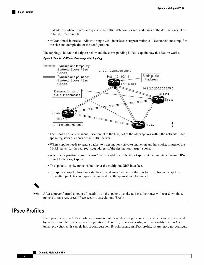
The topology shown in the figure below and the corresponding bullets explain how this feature works.Figure 1: Sample mGRE and IPsec Integration Topology
• Each spoke has a permanent IPsec tunnel to the hub, not to the other spokes within the network. Eachspoke registers as clients of the NHRP server.
• When a spoke needs to send a packet to a destination (private) subnet on another spoke, it queries theNHRP server for the real (outside) address of the destination (target) spoke.
• After the originating spoke “learns” the peer address of the target spoke, it can initiate a dynamic IPsectunnel to the target spoke.
• The spoke-to-spoke tunnel is built over the multipoint GRE interface.
• The spoke-to-spoke links are established on demand whenever there is traffic between the spokes.Thereafter, packets can bypass the hub and use the spoke-to-spoke tunnel.
After a preconfigured amount of inactivity on the spoke-to-spoke tunnels, the router will tear down thosetunnels to save resources (IPsec security associations [SAs]).
Note
IPsec ProfilesIPsec profiles abstract IPsec policy information into a single configuration entity, which can be referencedby name from other parts of the configuration. Therefore, users can configure functionality such as GREtunnel protection with a single line of configuration. By referencing an IPsec profile, the user need not configure
Dynamic Multipoint VPN4
Dynamic Multipoint VPNIPsec Profiles
an entire crypto map configuration. An IPsec profile contains only IPsec information; that is, it does notcontain any access list information or peering information.
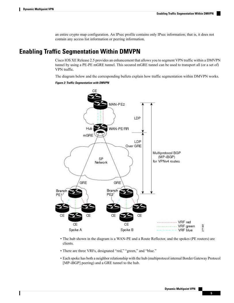
Enabling Traffic Segmentation Within DMVPNCisco IOSXERelease 2.5 provides an enhancement that allows you to segment VPN traffic within a DMVPNtunnel by using a PE-PE mGRE tunnel. This secured mGRE tunnel can be used to transport all (or a set of)VPN traffic.
The diagram below and the corresponding bullets explain how traffic segmentation within DMVPN works.Figure 2: Traffic Segmentation with DMVPN
• The hub shown in the diagram is a WAN-PE and a Route Reflector, and the spokes (PE routers) areclients.
• There are three VRFs, designated “red,” “green,” and “blue.”
• Each spoke has both a neighbor relationship with the hub (multiprotocol internal Border Gateway Protocol[MP-iBGP] peering) and a GRE tunnel to the hub.
Dynamic Multipoint VPN5
Dynamic Multipoint VPNEnabling Traffic Segmentation Within DMVPN
• Each spoke advertises its routes and VPN-IPv4 (VPNv4) prefixes to the hub.
• The hub sets its own IP address as the next-hop route for all the VPNv4 addresses it learns from thespokes and assigns a local MPLS label for each VPN when it advertises routes back to the spokes. As aresult, traffic from Spoke A to Spoke B is routed via the hub.
An example illustrates the process:
1. Spoke A advertises a VPNv4 route to the hub, and applies the label x to the VPN.
2. The hub changes the label to y when the hub advertises the route to Spoke B.
3. When Spoke B has traffic to send to Spoke A, it applies the y label, and the traffic goes to the hub.
4. The hub swaps the VPN label, by removing the y label and applying an x label, and sends the traffic toSpoke A.
NAT-Transparency Aware DMVPNDMVPN spokes are often situated behind a NAT router (which is often controlled by the Internet ServiceProvider [ISP] for the spoke site) with the outside interface address of the spoke router being dynamicallyassigned by the ISP using a private IP address (per Internet Engineering Task Force [IETF] RFC 1918).
With the NAT-Transparency Aware DMVPN enhancement, NHRP can learn and use the NAT public addressfor its mappings as long as IPsec transport mode is used (which is the recommended IPsec mode for DMVPNnetworks). It is recommended that all DMVPN routers be upgraded to the new code before you try to use theNAT-Transparency Aware DMVPN functionality even though spoke routers that are not behind NAT neednot be upgraded. In addition, you cannot convert upgraded spoke routers that are behind NAT to the newconfiguration (IPsec transport mode) until the hub routers have been upgraded.
With this NAT Transparency enhancement, the hub DMVPN router can be behind the static NAT. For thisfunctionality to be used, all the DMVPN spoke routers and hub routers must be upgraded, and IPsec must usetransport mode.
For these NAT-Transparency Aware enhancements to work, you must use IPsec transport mode on thetransform set. Also, even though NAT-Transparency (IKE and IPsec) can support two peers (IKE and IPsec)being translated to the same IP address (using the UDP ports to differentiate them), this functionality is notsupported for DMVPN.All DMVPN spokesmust have a unique IP address after they have beenNAT translated.They can have the same IP address before they are NAT translated.
The figure below illustrates a NAT-Transparency Aware DMVPN scenario.
DMVPN spokes behind NAT will participate in dynamic direct spoke-to-spoke tunnels. The spokes must bebehind NAT boxes that are preforming NAT, not PAT. The NAT box must translate the spoke to the sameoutside NAT IP address for the spoke-to-spoke connections as the NAT box does for the spoke-to-hubconnection. If there is more than one DMVPN spoke behind the same NAT box, the NAT box must translatethe DMVPN spokes to different outside NAT IP addresses. It is also likely that you may not be able to builda direct spoke-to-spoke tunnel between these spokes. If a spoke-to-spoke tunnel fails to form, the spoke-to-spokepackets will continue to be forwarded via the spoke-to-hub-spoke path.
Note
Dynamic Multipoint VPN6
Dynamic Multipoint VPNNAT-Transparency Aware DMVPN
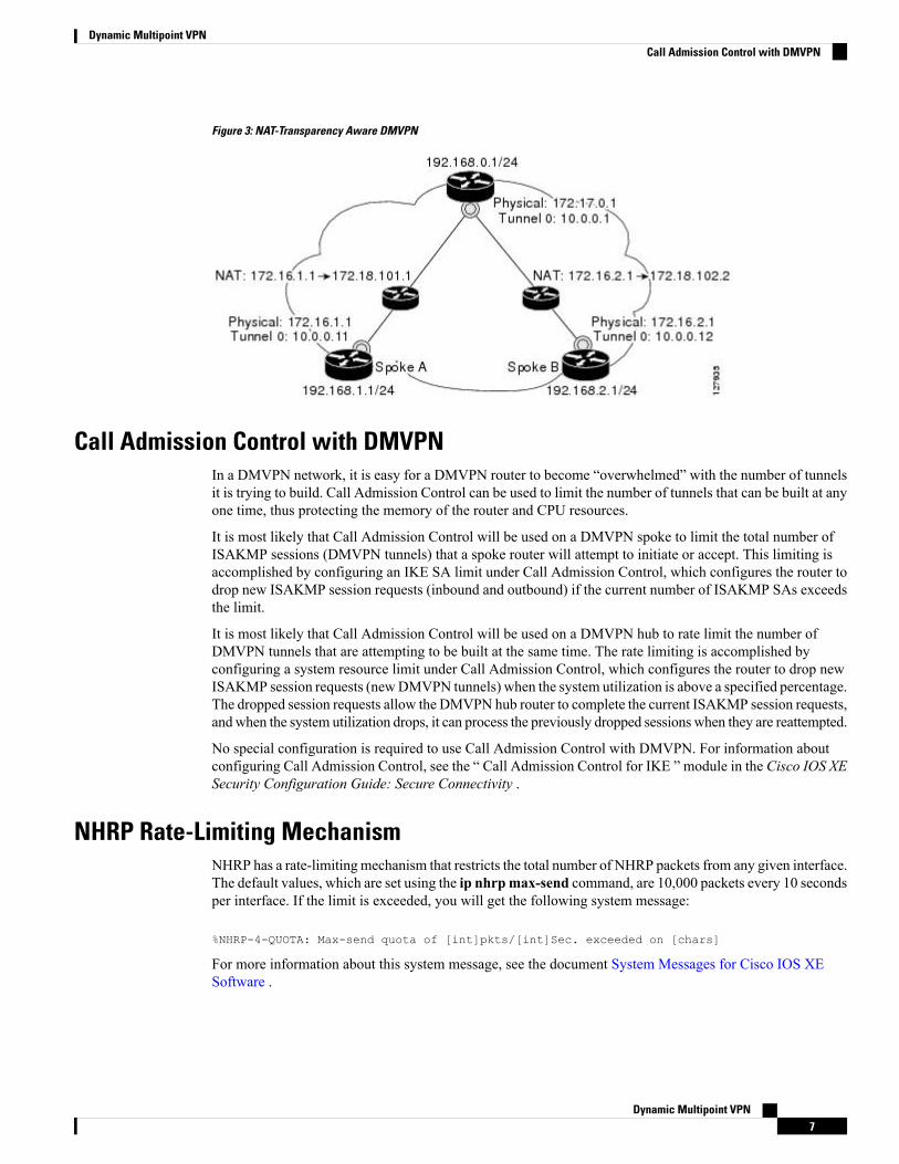
Figure 3: NAT-Transparency Aware DMVPN
Call Admission Control with DMVPNIn a DMVPN network, it is easy for a DMVPN router to become “overwhelmed” with the number of tunnelsit is trying to build. Call Admission Control can be used to limit the number of tunnels that can be built at anyone time, thus protecting the memory of the router and CPU resources.
It is most likely that Call Admission Control will be used on a DMVPN spoke to limit the total number ofISAKMP sessions (DMVPN tunnels) that a spoke router will attempt to initiate or accept. This limiting isaccomplished by configuring an IKE SA limit under Call Admission Control, which configures the router todrop new ISAKMP session requests (inbound and outbound) if the current number of ISAKMP SAs exceedsthe limit.
It is most likely that Call Admission Control will be used on a DMVPN hub to rate limit the number ofDMVPN tunnels that are attempting to be built at the same time. The rate limiting is accomplished byconfiguring a system resource limit under Call Admission Control, which configures the router to drop newISAKMP session requests (newDMVPN tunnels) when the system utilization is above a specified percentage.The dropped session requests allow the DMVPN hub router to complete the current ISAKMP session requests,and when the system utilization drops, it can process the previously dropped sessions when they are reattempted.
No special configuration is required to use Call Admission Control with DMVPN. For information aboutconfiguring Call Admission Control, see the “ Call Admission Control for IKE ” module in the Cisco IOS XESecurity Configuration Guide: Secure Connectivity .
NHRP Rate-Limiting MechanismNHRP has a rate-limitingmechanism that restricts the total number of NHRP packets from any given interface.The default values, which are set using the ip nhrpmax-send command, are 10,000 packets every 10 secondsper interface. If the limit is exceeded, you will get the following system message:
%NHRP-4-QUOTA: Max-send quota of [int]pkts/[int]Sec. exceeded on [chars]
For more information about this system message, see the document System Messages for Cisco IOS XESoftware .
Dynamic Multipoint VPN7
Dynamic Multipoint VPNCall Admission Control with DMVPN
How to Configure Dynamic Multipoint VPNTo enable mGRE and IPsec tunneling for hub and spoke routers, you must configure an IPsec profile thatuses a global IPsec policy template and configure your mGRE tunnel for IPsec encryption. This sectioncontains the following procedures:
Configuring an IPsec ProfileThe IPsec profile shares most of the same commands with the crypto map configuration, but only a subset ofthe commands are valid in an IPsec profile. Only commands that pertain to an IPsec policy can be issuedunder an IPsec profile; you cannot specify the IPsec peer address or the Access Control List (ACL) to matchthe packets that are to be encrypted.
Security threats, as well as the cryptographic technologies to help protect against them, are constantly changing.For more information about the latest Cisco cryptographic recommendations, see the Next GenerationEncryption (NGE) white paper.
Note
Before you begin
Before configuring an IPsec profile, you must define a transform set by using the crypto ipsec transform-setcommand.
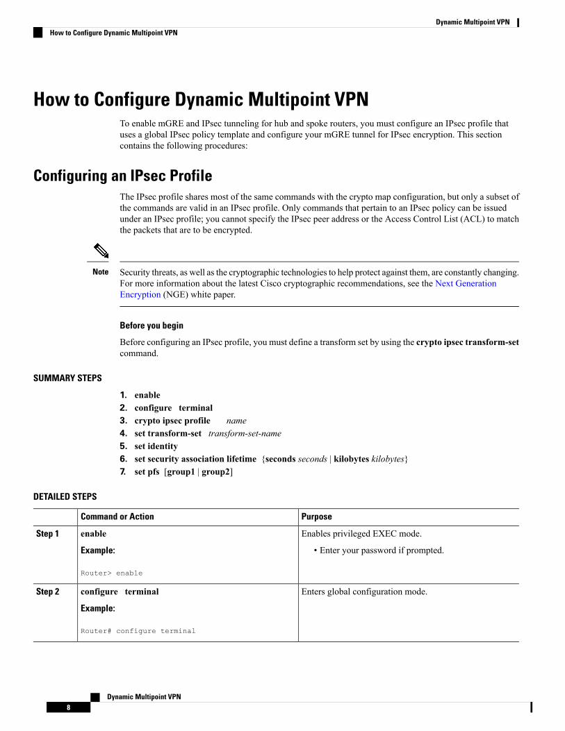
SUMMARY STEPS
1. enable2. configure terminal3. crypto ipsec profile name4. set transform-set transform-set-name5. set identity6. set security association lifetime {seconds seconds | kilobytes kilobytes}7. set pfs [group1 | group2]
DETAILED STEPS
PurposeCommand or Action
Enables privileged EXEC mode.enableStep 1
Example: • Enter your password if prompted.
Router> enable
Enters global configuration mode.configure terminal
Example:
Step 2
Router# configure terminal
Dynamic Multipoint VPN8
Dynamic Multipoint VPNHow to Configure Dynamic Multipoint VPN
PurposeCommand or Action
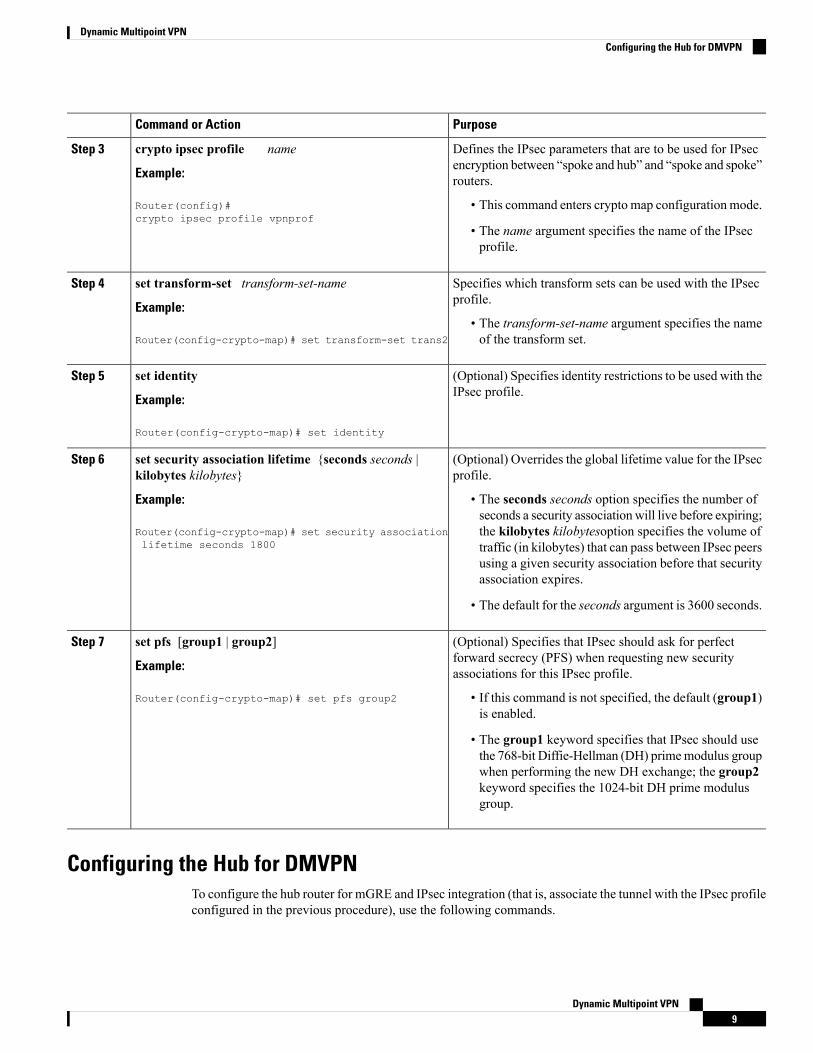
Defines the IPsec parameters that are to be used for IPsecencryption between “spoke and hub” and “spoke and spoke”routers.
crypto ipsec profile name
Example:
Router(config)#crypto ipsec profile vpnprof
Step 3
• This command enters crypto map configuration mode.
• The name argument specifies the name of the IPsecprofile.
Specifies which transform sets can be used with the IPsecprofile.
set transform-set transform-set-name
Example:
Step 4
• The transform-set-name argument specifies the nameof the transform set.Router(config-crypto-map)# set transform-set trans2
(Optional) Specifies identity restrictions to be used with theIPsec profile.
set identity
Example:
Step 5
Router(config-crypto-map)# set identity
(Optional) Overrides the global lifetime value for the IPsecprofile.
set security association lifetime {seconds seconds |kilobytes kilobytes}
Step 6
Example: • The seconds seconds option specifies the number ofseconds a security association will live before expiring;
Router(config-crypto-map)# set security associationlifetime seconds 1800
the kilobytes kilobytesoption specifies the volume oftraffic (in kilobytes) that can pass between IPsec peersusing a given security association before that securityassociation expires.
• The default for the seconds argument is 3600 seconds.
(Optional) Specifies that IPsec should ask for perfectforward secrecy (PFS) when requesting new securityassociations for this IPsec profile.
set pfs [group1 | group2]
Example:
Router(config-crypto-map)# set pfs group2
Step 7
• If this command is not specified, the default (group1)is enabled.
• The group1 keyword specifies that IPsec should usethe 768-bit Diffie-Hellman (DH) primemodulus groupwhen performing the new DH exchange; the group2keyword specifies the 1024-bit DH prime modulusgroup.
Configuring the Hub for DMVPNTo configure the hub router for mGRE and IPsec integration (that is, associate the tunnel with the IPsec profileconfigured in the previous procedure), use the following commands.
Dynamic Multipoint VPN9
Dynamic Multipoint VPNConfiguring the Hub for DMVPN

NHRP network IDs are locally significant and can be different. It makes sense from a deployment andmaintenance perspective to use unique network IDnumbers (using the ip nhrp network-id command) acrossall routers in a DMVPN network, but it is not necessary that they be the same.
Note
SUMMARY STEPS
1. enable2. configure terminal3. interface tunnel number4. ip address ip-address mask secondary5. ip mtu bytes6. ip nhrp authentication string7. ip nhrp map multicast dynamic8. ip nhrp network-id number9. tunnel source {ip-address | type number}10. tunnel key key-number11. tunnel mode gre multipoint12. Do one of the following:
• tunnel protection ipsec profile name• tunnel protection psk key
13. bandwidth kbps14. ip tcp adjust-mss max-segment-size15. ip nhrp holdtime seconds16. delay number
DETAILED STEPS
PurposeCommand or Action
Enables privileged EXEC mode.enableStep 1
Example: • Enter your password if prompted.
Router> enable
Enters global configuration mode.configure terminal
Example:
Step 2
Router# configure terminal
Configures a tunnel interface and enters interfaceconfiguration mode
interface tunnel number
Example:
Step 3
• The number argument specifies the number of thetunnel interface that you want to create or configure.Router(config)#
interface tunnel 5 There is no limit on the number of tunnel interfacesyou can create.
Dynamic Multipoint VPN10
Dynamic Multipoint VPNConfiguring the Hub for DMVPN
PurposeCommand or Action
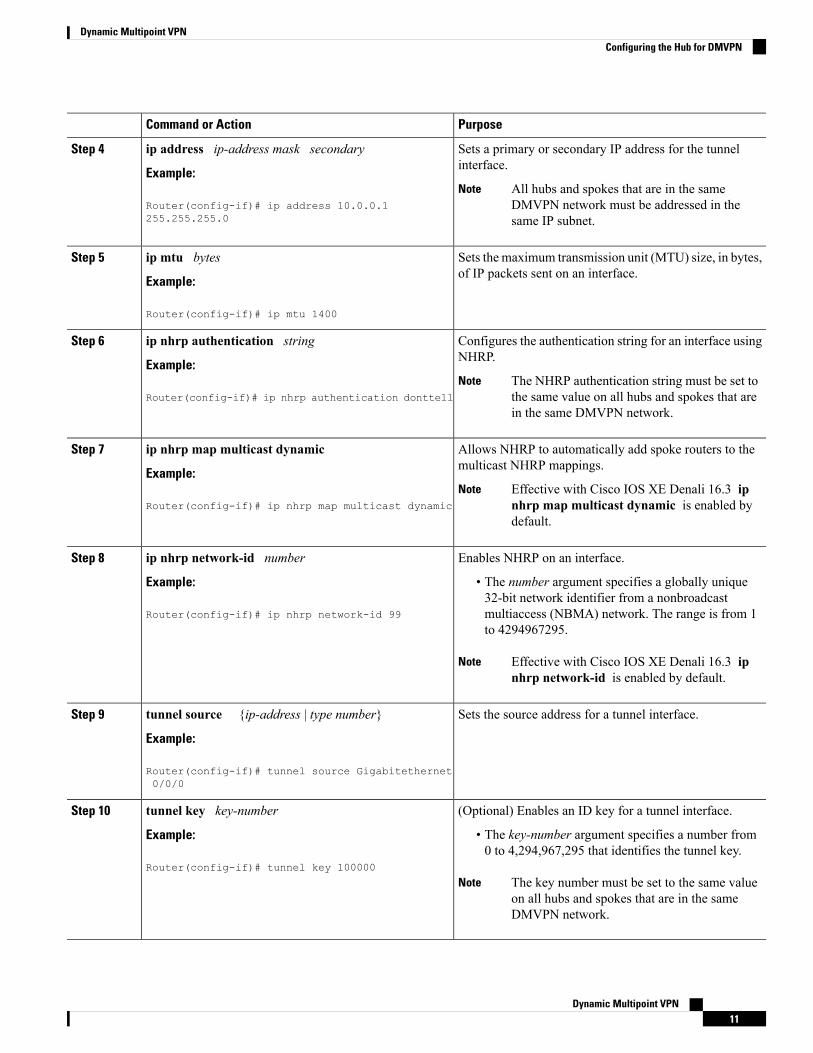
Sets a primary or secondary IP address for the tunnelinterface.
ip address ip-address mask secondary
Example:
Step 4
All hubs and spokes that are in the sameDMVPN network must be addressed in thesame IP subnet.
NoteRouter(config-if)# ip address 10.0.0.1255.255.255.0
Sets the maximum transmission unit (MTU) size, in bytes,of IP packets sent on an interface.
ip mtu bytes
Example:
Step 5
Router(config-if)# ip mtu 1400
Configures the authentication string for an interface usingNHRP.
ip nhrp authentication string
Example:
Step 6
The NHRP authentication string must be set tothe same value on all hubs and spokes that arein the same DMVPN network.
NoteRouter(config-if)# ip nhrp authentication donttell
Allows NHRP to automatically add spoke routers to themulticast NHRP mappings.
ip nhrp map multicast dynamic
Example:
Step 7
Effective with Cisco IOS XE Denali 16.3 ipnhrp map multicast dynamic is enabled bydefault.
NoteRouter(config-if)# ip nhrp map multicast dynamic
Enables NHRP on an interface.ip nhrp network-id numberStep 8
Example: • The number argument specifies a globally unique32-bit network identifier from a nonbroadcast
Router(config-if)# ip nhrp network-id 99 multiaccess (NBMA) network. The range is from 1to 4294967295.
Effective with Cisco IOS XE Denali 16.3 ipnhrp network-id is enabled by default.
Note
Sets the source address for a tunnel interface.tunnel source {ip-address | type number}
Example:
Step 9
Router(config-if)# tunnel source Gigabitethernet0/0/0
(Optional) Enables an ID key for a tunnel interface.tunnel key key-numberStep 10
Example: • The key-number argument specifies a number from0 to 4,294,967,295 that identifies the tunnel key.
Router(config-if)# tunnel key 100000
The key number must be set to the same valueon all hubs and spokes that are in the sameDMVPN network.
Note
Dynamic Multipoint VPN11
Dynamic Multipoint VPNConfiguring the Hub for DMVPN
PurposeCommand or Action
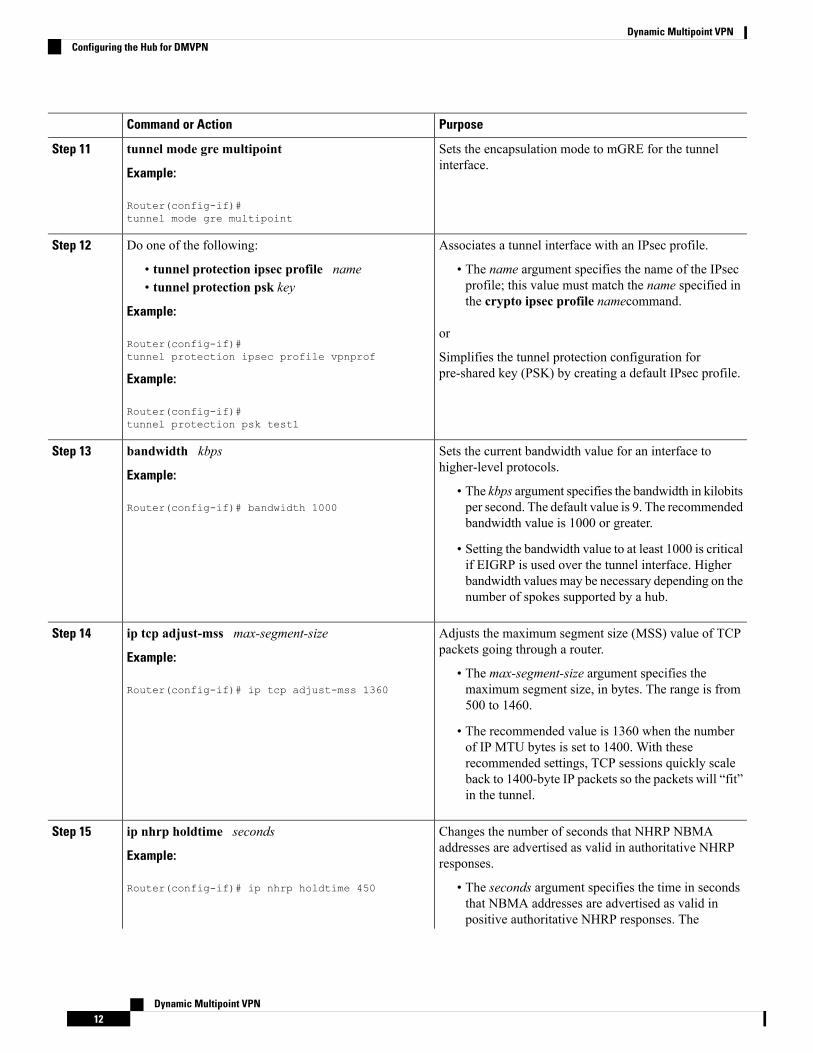
Sets the encapsulation mode to mGRE for the tunnelinterface.
tunnel mode gre multipoint
Example:
Step 11
Router(config-if)#tunnel mode gre multipoint
Associates a tunnel interface with an IPsec profile.Do one of the following:Step 12
• tunnel protection ipsec profile name • The name argument specifies the name of the IPsecprofile; this value must match the name specified inthe crypto ipsec profile namecommand.
• tunnel protection psk key
Example:
Router(config-if)#tunnel protection ipsec profile vpnprof
or
Simplifies the tunnel protection configuration forpre-shared key (PSK) by creating a default IPsec profile.Example:
Router(config-if)#tunnel protection psk test1
Sets the current bandwidth value for an interface tohigher-level protocols.
bandwidth kbps
Example:
Step 13
• The kbps argument specifies the bandwidth in kilobitsper second. The default value is 9. The recommendedbandwidth value is 1000 or greater.
Router(config-if)# bandwidth 1000
• Setting the bandwidth value to at least 1000 is criticalif EIGRP is used over the tunnel interface. Higherbandwidth values may be necessary depending on thenumber of spokes supported by a hub.
Adjusts the maximum segment size (MSS) value of TCPpackets going through a router.
ip tcp adjust-mss max-segment-size
Example:
Step 14
• The max-segment-size argument specifies themaximum segment size, in bytes. The range is from500 to 1460.
Router(config-if)# ip tcp adjust-mss 1360
• The recommended value is 1360 when the numberof IP MTU bytes is set to 1400. With theserecommended settings, TCP sessions quickly scaleback to 1400-byte IP packets so the packets will “fit”in the tunnel.
Changes the number of seconds that NHRP NBMAaddresses are advertised as valid in authoritative NHRPresponses.
ip nhrp holdtime seconds
Example:
Router(config-if)# ip nhrp holdtime 450
Step 15
• The seconds argument specifies the time in secondsthat NBMA addresses are advertised as valid inpositive authoritative NHRP responses. The
Dynamic Multipoint VPN12
Dynamic Multipoint VPNConfiguring the Hub for DMVPN
PurposeCommand or Action
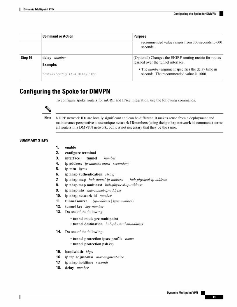
recommended value ranges from 300 seconds to 600seconds.
(Optional) Changes the EIGRP routing metric for routeslearned over the tunnel interface.
delay number
Example:
Step 16
• The number argument specifies the delay time inseconds. The recommended value is 1000.Router(config-if)# delay 1000
Configuring the Spoke for DMVPNTo configure spoke routers for mGRE and IPsec integration, use the following commands.
NHRP network IDs are locally significant and can be different. It makes sense from a deployment andmaintenance perspective to use unique network IDnumbers (using the ip nhrp network-id command) acrossall routers in a DMVPN network, but it is not necessary that they be the same.
Note
SUMMARY STEPS
1. enable2. configure terminal3. interface tunnel number4. ip address ip-address mask secondary5. ip mtu bytes6. ip nhrp authentication string7. ip nhrp map hub-tunnel-ip-address hub-physical-ip-address8. ip nhrp map multicast hub-physical-ip-address9. ip nhrp nhs hub-tunnel-ip-address10. ip nhrp network-id number11. tunnel source {ip-address | type number}12. tunnel key key-number13. Do one of the following:
• tunnel mode gre multipoint• tunnel destination hub-physical-ip-address
14. Do one of the following:
• tunnel protection ipsec profile name• tunnel protection psk key
15. bandwidth kbps16. ip tcp adjust-mss max-segment-size17. ip nhrp holdtime seconds18. delay number
Dynamic Multipoint VPN13
Dynamic Multipoint VPNConfiguring the Spoke for DMVPN
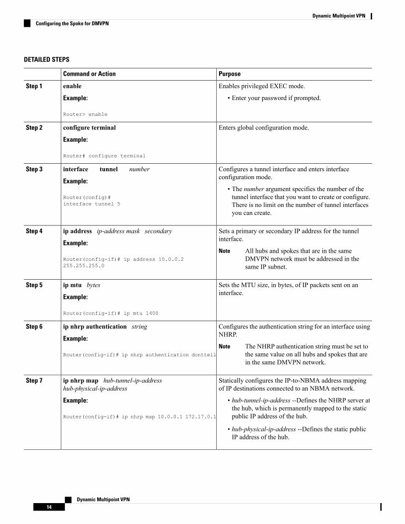
DETAILED STEPS
PurposeCommand or Action
Enables privileged EXEC mode.enableStep 1
Example: • Enter your password if prompted.
Router> enable
Enters global configuration mode.configure terminal
Example:
Step 2
Router# configure terminal
Configures a tunnel interface and enters interfaceconfiguration mode.
interface tunnel number
Example:
Step 3
• The number argument specifies the number of thetunnel interface that you want to create or configure.Router(config)#
interface tunnel 5 There is no limit on the number of tunnel interfacesyou can create.
Sets a primary or secondary IP address for the tunnelinterface.
ip address ip-address mask secondary
Example:
Step 4
All hubs and spokes that are in the sameDMVPN network must be addressed in thesame IP subnet.
NoteRouter(config-if)# ip address 10.0.0.2255.255.255.0
Sets the MTU size, in bytes, of IP packets sent on aninterface.
ip mtu bytes
Example:
Step 5
Router(config-if)# ip mtu 1400
Configures the authentication string for an interface usingNHRP.
ip nhrp authentication string
Example:
Step 6
The NHRP authentication string must be set tothe same value on all hubs and spokes that arein the same DMVPN network.
NoteRouter(config-if)# ip nhrp authentication donttell
Statically configures the IP-to-NBMA address mappingof IP destinations connected to an NBMA network.
ip nhrp map hub-tunnel-ip-addresshub-physical-ip-address
Step 7
Example: • hub-tunnel-ip-address --Defines the NHRP server atthe hub, which is permanently mapped to the staticpublic IP address of the hub.Router(config-if)# ip nhrp map 10.0.0.1 172.17.0.1
• hub-physical-ip-address --Defines the static publicIP address of the hub.
Dynamic Multipoint VPN14
Dynamic Multipoint VPNConfiguring the Spoke for DMVPN
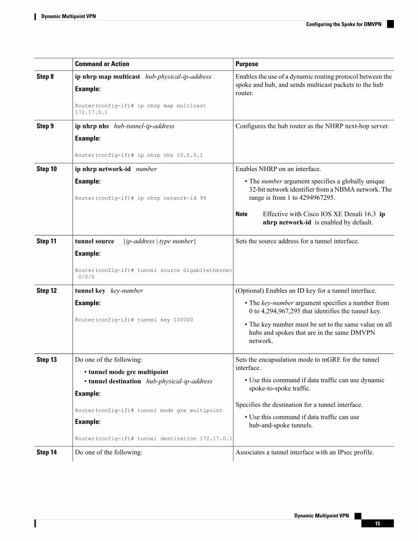
PurposeCommand or Action
Enables the use of a dynamic routing protocol between thespoke and hub, and sends multicast packets to the hubrouter.
ip nhrp map multicast hub-physical-ip-address
Example:
Router(config-if)# ip nhrp map multicast172.17.0.1
Step 8
Configures the hub router as the NHRP next-hop server.ip nhrp nhs hub-tunnel-ip-address
Example:
Step 9
Router(config-if)# ip nhrp nhs 10.0.0.1
Enables NHRP on an interface.ip nhrp network-id numberStep 10
Example: • The number argument specifies a globally unique32-bit network identifier from aNBMAnetwork. Therange is from 1 to 4294967295.Router(config-if)# ip nhrp network-id 99
Effective with Cisco IOS XE Denali 16.3 ipnhrp network-id is enabled by default.
Note
Sets the source address for a tunnel interface.tunnel source {ip-address | type number}
Example:
Step 11
Router(config-if)# tunnel source Gigabitethernet0/0/0
(Optional) Enables an ID key for a tunnel interface.tunnel key key-numberStep 12
Example: • The key-number argument specifies a number from0 to 4,294,967,295 that identifies the tunnel key.
Router(config-if)# tunnel key 100000• The key number must be set to the same value on allhubs and spokes that are in the same DMVPNnetwork.
Sets the encapsulation mode to mGRE for the tunnelinterface.
Do one of the following:Step 13
• tunnel mode gre multipoint• Use this command if data traffic can use dynamicspoke-to-spoke traffic.
• tunnel destination hub-physical-ip-address
Example:
Router(config-if)# tunnel mode gre multipointSpecifies the destination for a tunnel interface.
• Use this command if data traffic can usehub-and-spoke tunnels.Example:
Router(config-if)# tunnel destination 172.17.0.1
Associates a tunnel interface with an IPsec profile.Do one of the following:Step 14
Dynamic Multipoint VPN15
Dynamic Multipoint VPNConfiguring the Spoke for DMVPN
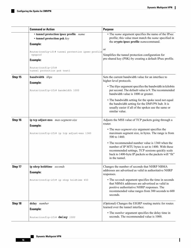
PurposeCommand or Action
• tunnel protection ipsec profile name • The name argument specifies the name of the IPsecprofile; this value must match the name specified inthe crypto ipsec profile namecommand.
• tunnel protection psk key
Example:
Router(config-if)# tunnel protection ipsec profilevpnprof
or
Simplifies the tunnel protection configuration forpre-shared key (PSK) by creating a default IPsec profile.Example:
Router(config-if)#tunnel protection psk test1
Sets the current bandwidth value for an interface tohigher-level protocols.
bandwidth kbps
Example:
Step 15
• The kbps argument specifies the bandwidth in kilobitsper second. The default value is 9. The recommendedbandwidth value is 1000 or greater.
Router(config-if)# bandwidth 1000
• The bandwidth setting for the spoke need not equalthe bandwidth setting for the DMVPN hub. It isusually easier if all of the spokes use the same orsimilar value.
Adjusts the MSS value of TCP packets going through arouter.
ip tcp adjust-mss max-segment-size
Example:
Step 16
• The max-segment-size argument specifies themaximum segment size, in bytes. The range is from500 to 1460.
Router(config-if)# ip tcp adjust-mss 1360
• The recommended number value is 1360 when thenumber of IP MTU bytes is set to 1400. With theserecommended settings, TCP sessions quickly scaleback to 1400-byte IP packets so the packets will “fit”in the tunnel.
Changes the number of seconds that NHRP NBMAaddresses are advertised as valid in authoritative NHRPresponses.
ip nhrp holdtime seconds
Example:
Router(config-if)# ip nhrp holdtime 450
Step 17
• The seconds argument specifies the time in secondsthat NBMA addresses are advertised as valid inpositive authoritative NHRP responses. Therecommended value ranges from 300 seconds to 600seconds.
(Optional) Changes the EIGRP routing metric for routeslearned over the tunnel interface.
delay number
Example:
Step 18
• The number argument specifies the delay time inseconds. The recommended value is 1000.Router(config-if)# delay 1000
Dynamic Multipoint VPN16
Dynamic Multipoint VPNConfiguring the Spoke for DMVPN
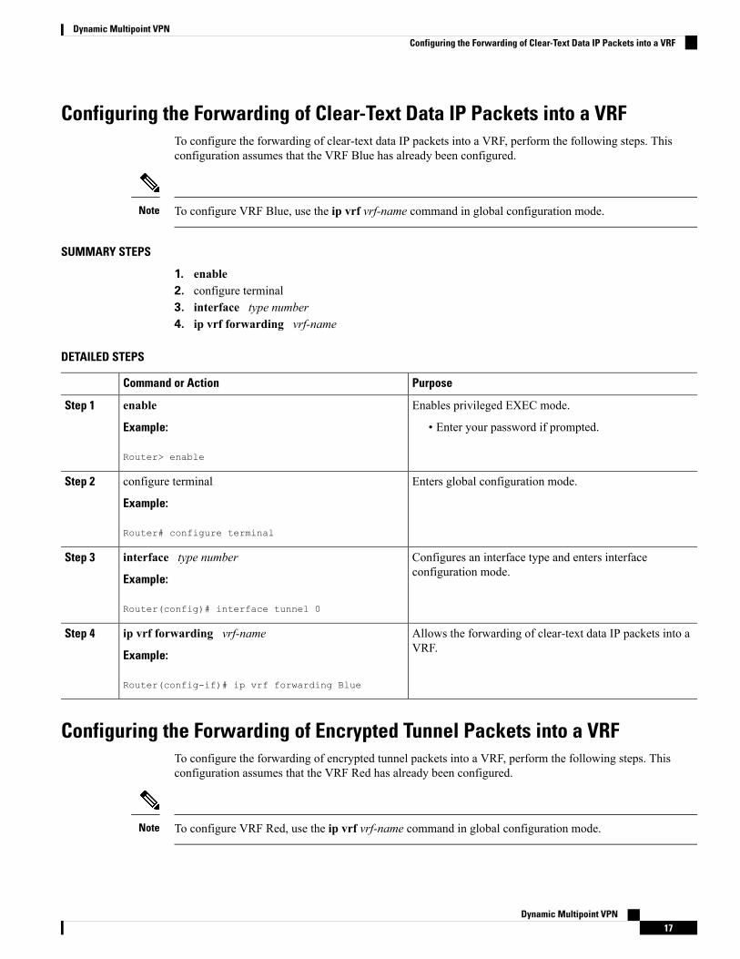
Configuring the Forwarding of Clear-Text Data IP Packets into a VRFTo configure the forwarding of clear-text data IP packets into a VRF, perform the following steps. Thisconfiguration assumes that the VRF Blue has already been configured.
To configure VRF Blue, use the ip vrf vrf-name command in global configuration mode.Note
SUMMARY STEPS
1. enable2. configure terminal3. interface type number4. ip vrf forwarding vrf-name
DETAILED STEPS
PurposeCommand or Action
Enables privileged EXEC mode.enableStep 1
Example: • Enter your password if prompted.
Router> enable
Enters global configuration mode.configure terminal
Example:
Step 2
Router# configure terminal
Configures an interface type and enters interfaceconfiguration mode.
interface type number
Example:
Step 3
Router(config)# interface tunnel 0
Allows the forwarding of clear-text data IP packets into aVRF.
ip vrf forwarding vrf-name
Example:
Step 4
Router(config-if)# ip vrf forwarding Blue
Configuring the Forwarding of Encrypted Tunnel Packets into a VRFTo configure the forwarding of encrypted tunnel packets into a VRF, perform the following steps. Thisconfiguration assumes that the VRF Red has already been configured.
To configure VRF Red, use the ip vrf vrf-name command in global configuration mode.Note
Dynamic Multipoint VPN17
Dynamic Multipoint VPNConfiguring the Forwarding of Clear-Text Data IP Packets into a VRF
SUMMARY STEPS
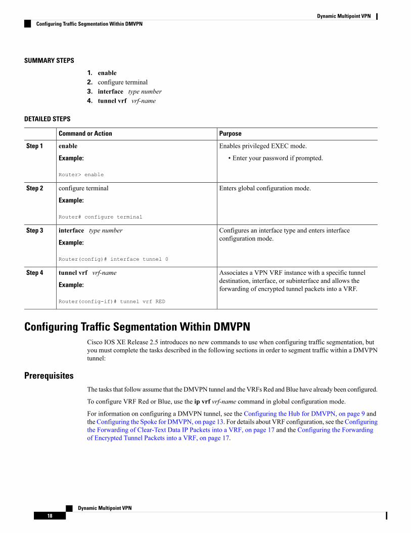
1. enable2. configure terminal3. interface type number4. tunnel vrf vrf-name
DETAILED STEPS
PurposeCommand or Action
Enables privileged EXEC mode.enableStep 1
Example: • Enter your password if prompted.
Router> enable
Enters global configuration mode.configure terminal
Example:
Step 2
Router# configure terminal
Configures an interface type and enters interfaceconfiguration mode.
interface type number
Example:
Step 3
Router(config)# interface tunnel 0
Associates a VPN VRF instance with a specific tunneldestination, interface, or subinterface and allows theforwarding of encrypted tunnel packets into a VRF.
tunnel vrf vrf-name
Example:
Router(config-if)# tunnel vrf RED
Step 4
Configuring Traffic Segmentation Within DMVPNCisco IOS XE Release 2.5 introduces no new commands to use when configuring traffic segmentation, butyou must complete the tasks described in the following sections in order to segment traffic within a DMVPNtunnel:
PrerequisitesThe tasks that follow assume that the DMVPN tunnel and the VRFs Red and Blue have already been configured.
To configure VRF Red or Blue, use the ip vrf vrf-name command in global configuration mode.
For information on configuring a DMVPN tunnel, see the Configuring the Hub for DMVPN, on page 9 andthe Configuring the Spoke for DMVPN, on page 13. For details about VRF configuration, see the Configuringthe Forwarding of Clear-Text Data IP Packets into a VRF, on page 17 and the Configuring the Forwardingof Encrypted Tunnel Packets into a VRF, on page 17.
Dynamic Multipoint VPN18
Dynamic Multipoint VPNConfiguring Traffic Segmentation Within DMVPN
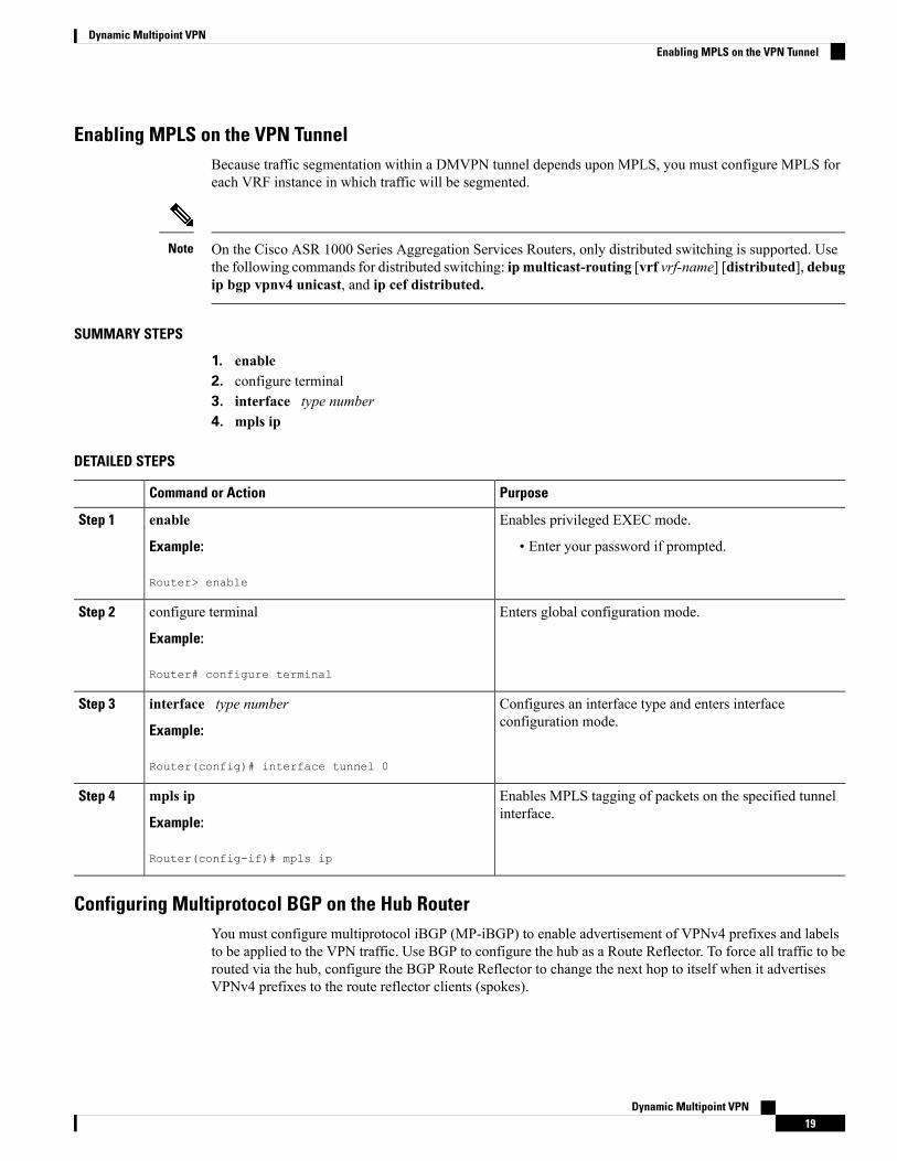
Enabling MPLS on the VPN TunnelBecause traffic segmentation within a DMVPN tunnel depends upon MPLS, you must configure MPLS foreach VRF instance in which traffic will be segmented.
On the Cisco ASR 1000 Series Aggregation Services Routers, only distributed switching is supported. Usethe following commands for distributed switching: ip multicast-routing [vrf vrf-name] [distributed], debugip bgp vpnv4 unicast, and ip cef distributed.
Note
SUMMARY STEPS
1. enable2. configure terminal3. interface type number4. mpls ip
DETAILED STEPS
PurposeCommand or Action
Enables privileged EXEC mode.enableStep 1
Example: • Enter your password if prompted.
Router> enable
Enters global configuration mode.configure terminal
Example:
Step 2
Router# configure terminal
Configures an interface type and enters interfaceconfiguration mode.
interface type number
Example:
Step 3
Router(config)# interface tunnel 0
Enables MPLS tagging of packets on the specified tunnelinterface.
mpls ip
Example:
Step 4
Router(config-if)# mpls ip
Configuring Multiprotocol BGP on the Hub RouterYou must configure multiprotocol iBGP (MP-iBGP) to enable advertisement of VPNv4 prefixes and labelsto be applied to the VPN traffic. Use BGP to configure the hub as a Route Reflector. To force all traffic to berouted via the hub, configure the BGP Route Reflector to change the next hop to itself when it advertisesVPNv4 prefixes to the route reflector clients (spokes).
Dynamic Multipoint VPN19
Dynamic Multipoint VPNEnabling MPLS on the VPN Tunnel
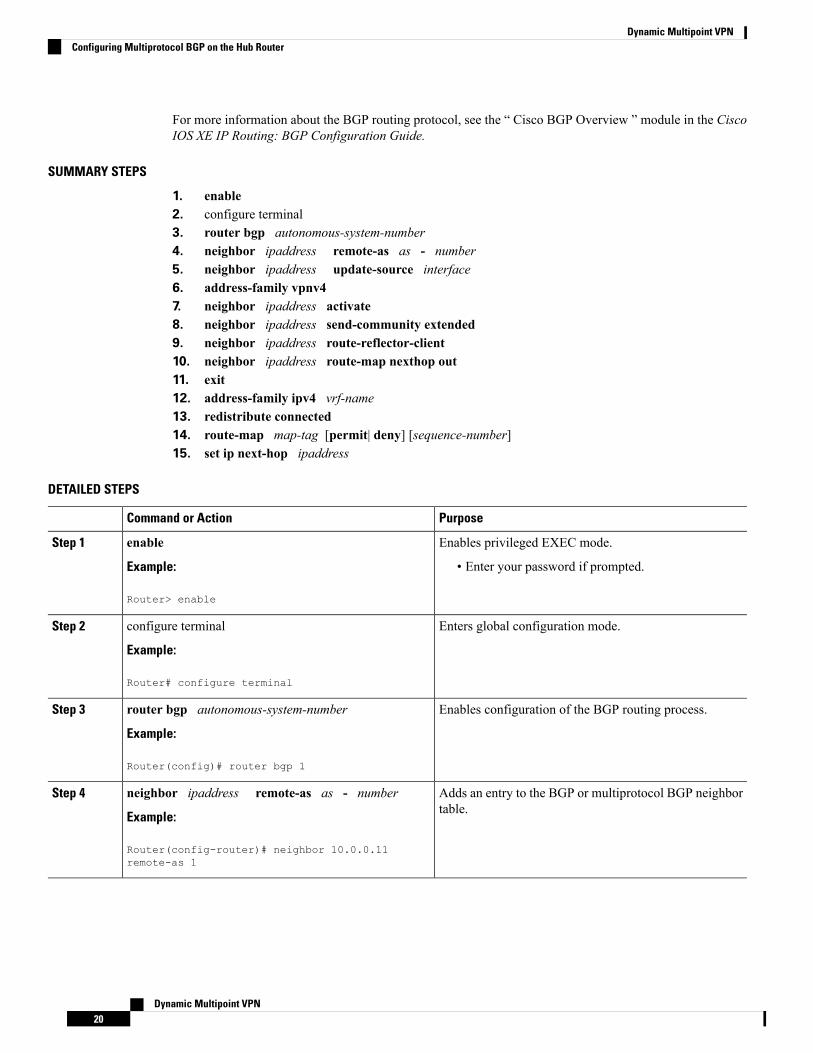
For more information about the BGP routing protocol, see the “ Cisco BGP Overview ” module in the CiscoIOS XE IP Routing: BGP Configuration Guide.
SUMMARY STEPS
1. enable2. configure terminal3. router bgp autonomous-system-number4. neighbor ipaddress remote-as as - number5. neighbor ipaddress update-source interface6. address-family vpnv47. neighbor ipaddress activate8. neighbor ipaddress send-community extended9. neighbor ipaddress route-reflector-client10. neighbor ipaddress route-map nexthop out11. exit12. address-family ipv4 vrf-name13. redistribute connected14. route-map map-tag [permit| deny] [sequence-number]15. set ip next-hop ipaddress
DETAILED STEPS
PurposeCommand or Action
Enables privileged EXEC mode.enableStep 1
Example: • Enter your password if prompted.
Router> enable
Enters global configuration mode.configure terminal
Example:
Step 2
Router# configure terminal
Enables configuration of the BGP routing process.router bgp autonomous-system-number
Example:
Step 3
Router(config)# router bgp 1
Adds an entry to the BGP or multiprotocol BGP neighbortable.
neighbor ipaddress remote-as as - number
Example:
Step 4
Router(config-router)# neighbor 10.0.0.11remote-as 1
Dynamic Multipoint VPN20
Dynamic Multipoint VPNConfiguring Multiprotocol BGP on the Hub Router
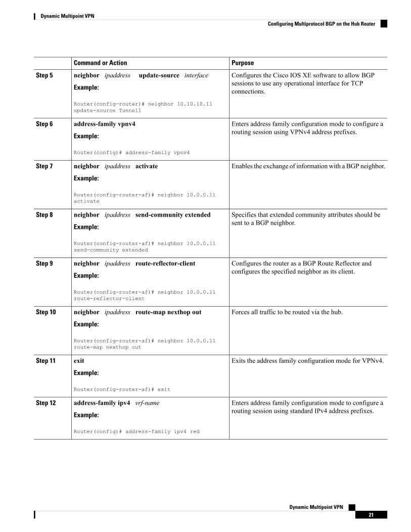
PurposeCommand or Action
Configures the Cisco IOS XE software to allow BGPsessions to use any operational interface for TCPconnections.
neighbor ipaddress update-source interface
Example:
Router(config-router)# neighbor 10.10.10.11update-source Tunnel1
Step 5
Enters address family configuration mode to configure arouting session using VPNv4 address prefixes.
address-family vpnv4
Example:
Step 6
Router(config)# address-family vpnv4
Enables the exchange of information with a BGP neighbor.neighbor ipaddress activate
Example:
Step 7
Router(config-router-af)# neighbor 10.0.0.11activate
Specifies that extended community attributes should besent to a BGP neighbor.
neighbor ipaddress send-community extended
Example:
Step 8
Router(config-router-af)# neighbor 10.0.0.11send-community extended
Configures the router as a BGP Route Reflector andconfigures the specified neighbor as its client.
neighbor ipaddress route-reflector-client
Example:
Step 9
Router(config-router-af)# neighbor 10.0.0.11route-reflector-client
Forces all traffic to be routed via the hub.neighbor ipaddress route-map nexthop out
Example:
Step 10
Router(config-router-af)# neighbor 10.0.0.11route-map nexthop out
Exits the address family configuration mode for VPNv4.exit
Example:
Step 11
Router(config-router-af)# exit
Enters address family configuration mode to configure arouting session using standard IPv4 address prefixes.
address-family ipv4 vrf-name
Example:
Step 12
Router(config)# address-family ipv4 red
Dynamic Multipoint VPN21
Dynamic Multipoint VPNConfiguring Multiprotocol BGP on the Hub Router
PurposeCommand or Action
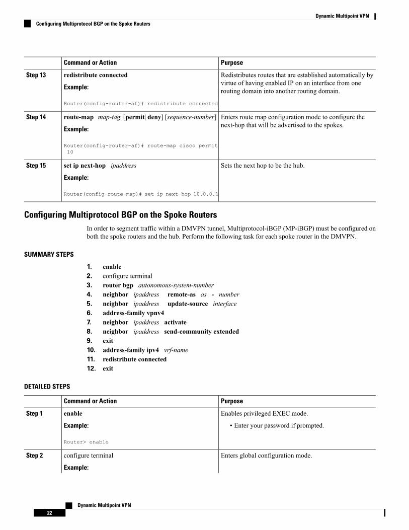
Redistributes routes that are established automatically byvirtue of having enabled IP on an interface from onerouting domain into another routing domain.
redistribute connected
Example:
Router(config-router-af)# redistribute connected
Step 13
Enters route map configuration mode to configure thenext-hop that will be advertised to the spokes.
route-map map-tag [permit| deny] [sequence-number]
Example:
Step 14
Router(config-router-af)# route-map cisco permit10
Sets the next hop to be the hub.set ip next-hop ipaddress
Example:
Step 15
Router(config-route-map)# set ip next-hop 10.0.0.1
Configuring Multiprotocol BGP on the Spoke RoutersIn order to segment traffic within a DMVPN tunnel, Multiprotocol-iBGP (MP-iBGP) must be configured onboth the spoke routers and the hub. Perform the following task for each spoke router in the DMVPN.
SUMMARY STEPS
1. enable2. configure terminal3. router bgp autonomous-system-number4. neighbor ipaddress remote-as as - number5. neighbor ipaddress update-source interface6. address-family vpnv47. neighbor ipaddress activate8. neighbor ipaddress send-community extended9. exit10. address-family ipv4 vrf-name11. redistribute connected12. exit
DETAILED STEPS
PurposeCommand or Action
Enables privileged EXEC mode.enableStep 1
Example: • Enter your password if prompted.
Router> enable
Enters global configuration mode.configure terminal
Example:
Step 2
Dynamic Multipoint VPN22
Dynamic Multipoint VPNConfiguring Multiprotocol BGP on the Spoke Routers
PurposeCommand or Action
Router# configure terminal
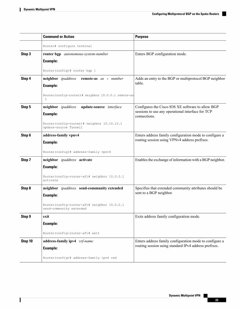
Enters BGP configuration mode.router bgp autonomous-system-number
Example:
Step 3
Router(config)# router bgp 1
Adds an entry to the BGP or multiprotocol BGP neighbortable.
neighbor ipaddress remote-as as - number
Example:
Step 4
Router(config-router)# neighbor 10.0.0.1 remote-as1
Configures the Cisco IOS XE software to allow BGPsessions to use any operational interface for TCPconnections.
neighbor ipaddress update-source interface
Example:
Router(config-router)# neighbor 10.10.10.1update-source Tunnel1
Step 5
Enters address family configuration mode to configure arouting session using VPNv4 address prefixes.
address-family vpnv4
Example:
Step 6
Router(config)# address-family vpnv4
Enables the exchange of information with a BGP neighbor.neighbor ipaddress activate
Example:
Step 7
Router(config-router-af)# neighbor 10.0.0.1activate
Specifies that extended community attributes should besent to a BGP neighbor.
neighbor ipaddress send-community extended
Example:
Step 8
Router(config-router-af)# neighbor 10.0.0.1send-community extended
Exits address family configuration mode.exit
Example:
Step 9
Router(config-router-af)# exit
Enters address family configuration mode to configure arouting session using standard IPv4 address prefixes.
address-family ipv4 vrf-name
Example:
Step 10
Router(config)# address-family ipv4 red
Dynamic Multipoint VPN23
Dynamic Multipoint VPNConfiguring Multiprotocol BGP on the Spoke Routers
PurposeCommand or Action
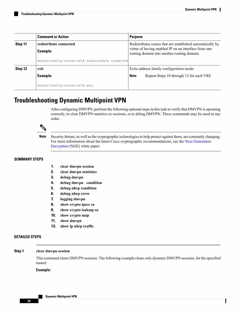
Redistributes routes that are established automatically byvirtue of having enabled IP on an interface from onerouting domain into another routing domain.
redistribute connected
Example:
Router(config-router-af)# redistribute connected
Step 11
Exits address family configuration mode.exitStep 12
Example: Repeat Steps 10 through 12 for each VRF.Note
Router(config-router-af)# exit
Troubleshooting Dynamic Multipoint VPNAfter configuring DMVPN, perform the following optional steps in this task to verify that DMVPN is operatingcorrectly, to clear DMVPN statistics or sessions, or to debug DMVPN. These commands may be used in anyorder.
Security threats, as well as the cryptographic technologies to help protect against them, are constantly changing.For more information about the latest Cisco cryptographic recommendations, see the Next GenerationEncryption (NGE) white paper.
Note
SUMMARY STEPS
1. clear dmvpn session2. clear dmvpn statistics3. debug dmvpn4. debug dmvpn condition5. debug nhrp condition6. debug nhrp error7. logging dmvpn8. show crypto ipsec sa9. show crypto isakmp sa10. show crypto map11. show dmvpn12. show ip nhrp traffic
DETAILED STEPS
Step 1 clear dmvpn session
This command clears DMVPN sessions. The following example clears only dynamic DMVPN sessions, for the specifiedtunnel:
Example:
Dynamic Multipoint VPN24
Dynamic Multipoint VPNTroubleshooting Dynamic Multipoint VPN
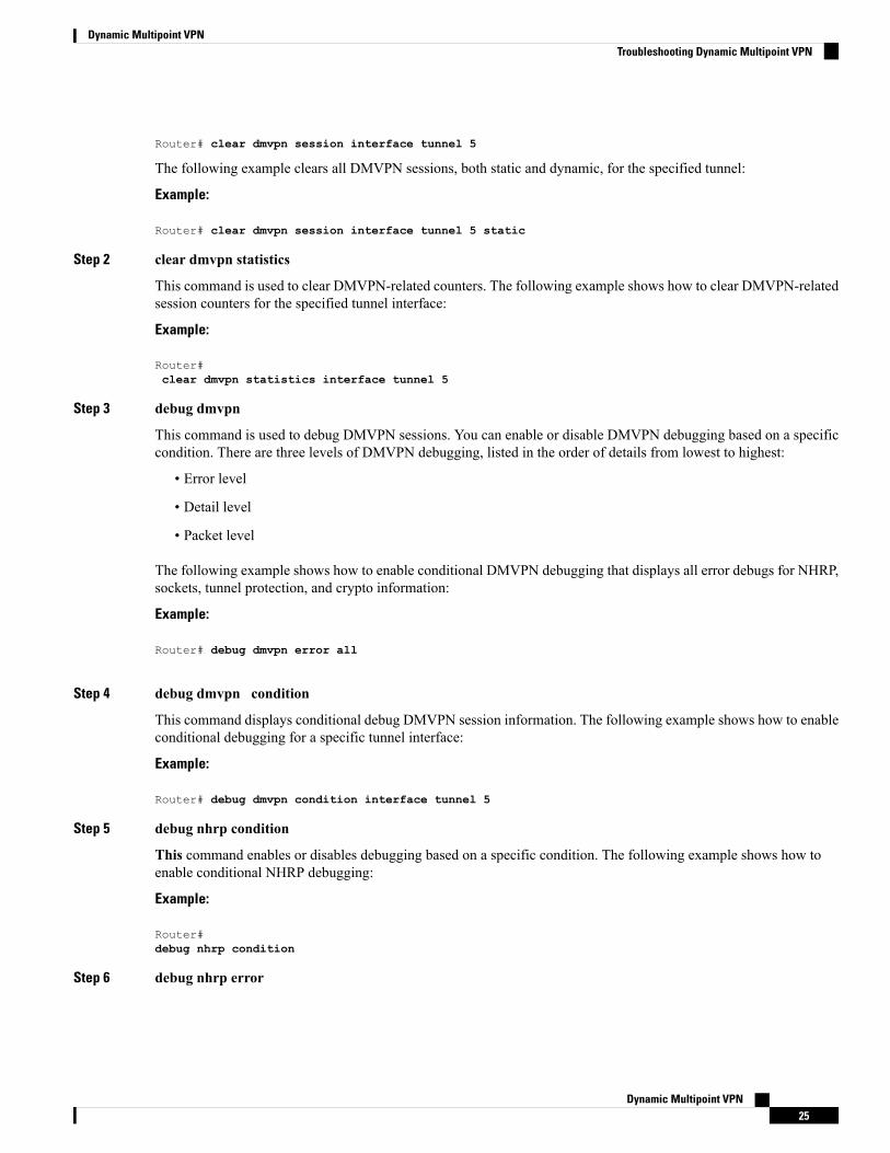
Router# clear dmvpn session interface tunnel 5
The following example clears all DMVPN sessions, both static and dynamic, for the specified tunnel:
Example:
Router# clear dmvpn session interface tunnel 5 static
Step 2 clear dmvpn statistics
This command is used to clear DMVPN-related counters. The following example shows how to clear DMVPN-relatedsession counters for the specified tunnel interface:
Example:
Router#clear dmvpn statistics interface tunnel 5
Step 3 debug dmvpn
This command is used to debug DMVPN sessions. You can enable or disable DMVPN debugging based on a specificcondition. There are three levels of DMVPN debugging, listed in the order of details from lowest to highest:
• Error level
• Detail level
• Packet level
The following example shows how to enable conditional DMVPN debugging that displays all error debugs for NHRP,sockets, tunnel protection, and crypto information:
Example:
Router# debug dmvpn error all
Step 4 debug dmvpn condition
This command displays conditional debug DMVPN session information. The following example shows how to enableconditional debugging for a specific tunnel interface:
Example:
Router# debug dmvpn condition interface tunnel 5
Step 5 debug nhrp condition
This command enables or disables debugging based on a specific condition. The following example shows how toenable conditional NHRP debugging:
Example:
Router#debug nhrp condition
Step 6 debug nhrp error
Dynamic Multipoint VPN25
Dynamic Multipoint VPNTroubleshooting Dynamic Multipoint VPN

This command displays information about NHRP error activity. The following example shows how to enable debuggingfor NHRP error messages:
Example:
Router#debug nhrp error
Step 7 logging dmvpn
This command is used to enable DMVPN system logging. The following example shows how to enable DMVPNsystem logging at the rate of 1 message every 20 seconds:
Example:
Router(config)#logging dmvpn rate-limit 20
The following example shows a sample system log with DMVPN messages:
Example:
%DMVPN-7-CRYPTO_SS: Tunnel101-192.0.2.1 socket is UP%DMVPN-5-NHRP_NHS: Tunnel101 192.0.2.251 is UP%DMVPN-5-NHRP_CACHE: Client 192.0.2.2 on Tunnel1 Registered.%DMVPN-5-NHRP_CACHE: Client 192.0.2.2 on Tunnel101 came UP.%DMVPN-3-NHRP_ERROR: Registration Request failed for 192.0.2.251 on Tunnel101
Step 8 show crypto ipsec sa
This command displays the settings used by the current SAs. The following example output shows the IPsec SA statusof only the active device:
Example:
Router#show crypto ipsec sa activeinterface: gigabitethernet0/0/0
Crypto map tag: to-peer-outside, local addr 209.165.201.3protected vrf: (nonelocal ident (addr/mask/prot/port): (192.168.0.1/255.255.255.255/0/0)remote ident (addr/mask/prot/port): (172.16.0.1/255.255.255.255/0/0)current_peer 209.165.200.225 port 500PERMIT, flags={origin_is_acl,}#pkts encaps: 3, #pkts encrypt: 3, #pkts digest: 3#pkts decaps: 4, #pkts decrypt: 4, #pkts verify: 4#pkts compressed: 0, #pkts decompressed: 0#pkts not compressed: 0, #pkts compr. failed: 0#pkts not decompressed: 0, #pkts decompress failed: 0#send errors 0, #recv errors 0local crypto endpt.: 209.165.201.3, remote crypto endpt.: 209.165.200.225path mtu 1500, media mtu 1500current outbound spi: 0xD42904F0(3559458032)inbound esp sas:spi: 0xD3E9ABD0(3555306448)transform: esp-3des ,in use settings ={Tunnel, }conn id: 2006, flow_id: 6, crypto map: to-peer-outsidesa timing: remaining key lifetime (k/sec): (4586265/3542)HA last key lifetime sent(k): (4586267)ike_cookies: 9263635C CA4B4E99 C14E908E 8EE2D79CIV size: 8 bytes
Dynamic Multipoint VPN26
Dynamic Multipoint VPNTroubleshooting Dynamic Multipoint VPN
replay detection support: YStatus: ACTIVE
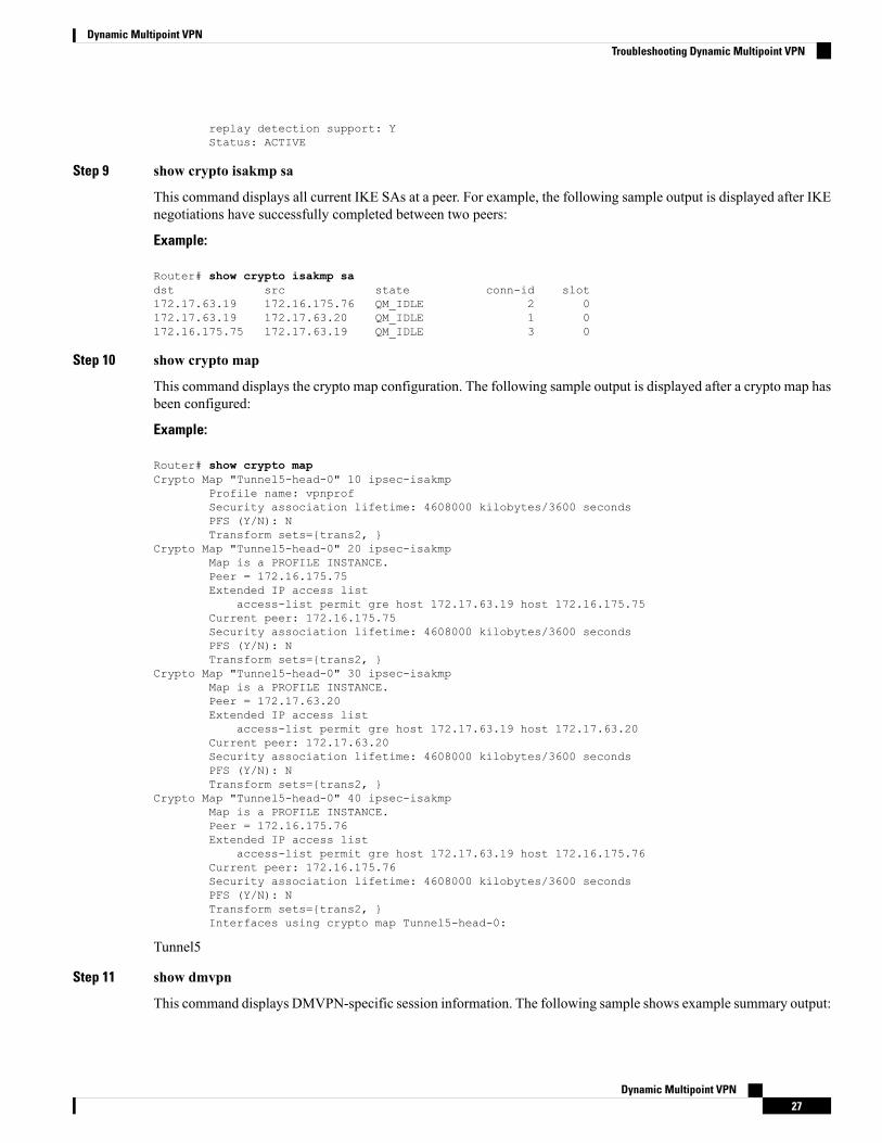
Step 9 show crypto isakmp sa
This command displays all current IKE SAs at a peer. For example, the following sample output is displayed after IKEnegotiations have successfully completed between two peers:
Example:
Router# show crypto isakmp sadst src state conn-id slot172.17.63.19 172.16.175.76 QM_IDLE 2 0172.17.63.19 172.17.63.20 QM_IDLE 1 0172.16.175.75 172.17.63.19 QM_IDLE 3 0
Step 10 show crypto map
This command displays the crypto map configuration. The following sample output is displayed after a crypto map hasbeen configured:
Example:
Router# show crypto mapCrypto Map "Tunnel5-head-0" 10 ipsec-isakmp
Profile name: vpnprofSecurity association lifetime: 4608000 kilobytes/3600 secondsPFS (Y/N): NTransform sets={trans2, }
Crypto Map "Tunnel5-head-0" 20 ipsec-isakmpMap is a PROFILE INSTANCE.Peer = 172.16.175.75Extended IP access list
access-list permit gre host 172.17.63.19 host 172.16.175.75Current peer: 172.16.175.75Security association lifetime: 4608000 kilobytes/3600 secondsPFS (Y/N): NTransform sets={trans2, }
Crypto Map "Tunnel5-head-0" 30 ipsec-isakmpMap is a PROFILE INSTANCE.Peer = 172.17.63.20Extended IP access list
access-list permit gre host 172.17.63.19 host 172.17.63.20Current peer: 172.17.63.20Security association lifetime: 4608000 kilobytes/3600 secondsPFS (Y/N): NTransform sets={trans2, }
Crypto Map "Tunnel5-head-0" 40 ipsec-isakmpMap is a PROFILE INSTANCE.Peer = 172.16.175.76Extended IP access list
access-list permit gre host 172.17.63.19 host 172.16.175.76Current peer: 172.16.175.76Security association lifetime: 4608000 kilobytes/3600 secondsPFS (Y/N): NTransform sets={trans2, }Interfaces using crypto map Tunnel5-head-0:
Tunnel5
Step 11 show dmvpn
This command displays DMVPN-specific session information. The following sample shows example summary output:
Dynamic Multipoint VPN27
Dynamic Multipoint VPNTroubleshooting Dynamic Multipoint VPN
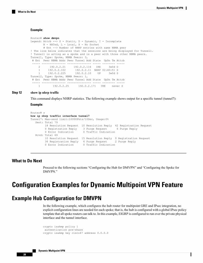
Example:
Router# show dmvpnLegend: Attrb --> S - Static, D - Dynamic, I - Incomplete
N - NATed, L - Local, X - No Socket# Ent --> Number of NHRP entries with same NBMA peer
! The line below indicates that the sessions are being displayed for Tunnel1.! Tunnel1 is acting as a spoke and is a peer with three other NBMA peers.Tunnel1, Type: Spoke, NBMA Peers: 3,# Ent Peer NBMA Addr Peer Tunnel Add State UpDn Tm Attrb----- --------------- --------------- ----- -------- -----
2 192.0.2.21 192.0.2.116 IKE 3w0d D1 192.0.2.102 192.0.2.11 NHRP 02:40:51 S1 192.0.2.225 192.0.2.10 UP 3w0d S
Tunnel2, Type: Spoke, NBMA Peers: 1,# Ent Peer NBMA Addr Peer Tunnel Add State UpDn Tm Attrb----- --------------- --------------- ----- -------- -----
1 192.0.2.25 192.0.2.171 IKE never S
Step 12 show ip nhrp traffic
This command displays NHRP statistics. The following example shows output for a specific tunnel (tunnel7):
Example:
Router# show ip nhrp traffic interface tunnel7Tunnel7: Max-send limit:10000Pkts/10Sec, Usage:0%
Sent: Total 7918 Resolution Request 10 Resolution Reply 42 Registration Request0 Registration Reply 3 Purge Request 6 Purge Reply0 Error Indication 0 Traffic Indication
Rcvd: Total 6910 Resolution Request 15 Resolution Reply 0 Registration Request36 Registration Reply 6 Purge Request 2 Purge Reply0 Error Indication 0 Traffic Indication
What to Do NextProceed to the following sections “Configuring the Hub for DMVPN” and “Configuring the Spoke forDMVPN.”
Configuration Examples for Dynamic Multipoint VPN Feature
Example Hub Configuration for DMVPNIn the following example, which configures the hub router for multipoint GRE and IPsec integration, noexplicit configuration lines are needed for each spoke; that is, the hub is configured with a global IPsec policytemplate that all spoke routers can talk to. In this example, EIGRP is configured to run over the private physicalinterface and the tunnel interface.
crypto isakmp policy 1authentication pre-sharecrypto isakmp key cisco47 address 0.0.0.0
Dynamic Multipoint VPN28
Dynamic Multipoint VPNWhat to Do Next
!crypto ipsec transform-set trans2 esp-des esp-md5-hmacmode transport!crypto ipsec profile vpnprofset transform-set trans2!interface Tunnel0bandwidth 1000ip address 10.0.0.1 255.255.255.0! Ensures longer packets are fragmented before they are encrypted; otherwise, the receivingrouter would have to do the reassembly.ip mtu 1400! The following line must match on all nodes that “want to use” this mGRE tunnel:ip nhrp authentication donttell! Note that the next line is required only on the hub.ip nhrp map multicast dynamic! The following line must match on all nodes that want to use this mGRE tunnel:ip nhrp network-id 99ip nhrp holdtime 300! Turns off split horizon on the mGRE tunnel interface; otherwise, EIGRP will not advertiseroutes that are learned via the mGRE interface back out that interface.no ip split-horizon eigrp 1! Enables dynamic, direct spoke-to-spoke tunnels when using EIGRP.no ip next-hop-self eigrp 1ip tcp adjust-mss 1360delay 1000! Sets IPsec peer address to Ethernet interface’s public address.tunnel source Gigabitethernet 0/0/0tunnel mode gre multipoint! The following line must match on all nodes that want to use this mGRE tunnel.tunnel key 100000tunnel protection ipsec profile vpnprof!interface FastEthernet0/0/0ip address 172.17.0.1 255.255.255.0!interface FastEthernet0/0/1ip address 192.168.0.1 255.255.255.0!router eigrp 1network 10.0.0.0 0.0.0.255network 192.168.0.0 0.0.0.255!
For information about defining and configuring ISAKMP profiles, see the “ Certificate to ISAKMP ProfileMapping ” module in the Cisco IOS XE Security Configuration Guide: Secure Connectivity .
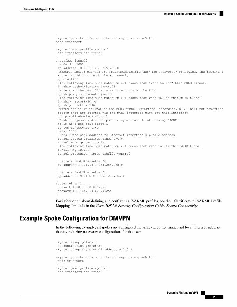
Example Spoke Configuration for DMVPNIn the following example, all spokes are configured the same except for tunnel and local interface address,thereby reducing necessary configurations for the user:
crypto isakmp policy 1authentication pre-sharecrypto isakmp key cisco47 address 0.0.0.0!crypto ipsec transform-set trans2 esp-des esp-md5-hmacmode transport!crypto ipsec profile vpnprofset transform-set trans2
Dynamic Multipoint VPN29
Dynamic Multipoint VPNExample Spoke Configuration for DMVPN
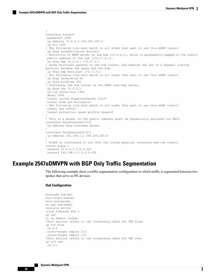
!interface Tunnel0bandwidth 1000ip address 10.0.0.2 255.255.255.0ip mtu 1400! The following line must match on all nodes that want to use this mGRE tunnel:ip nhrp authentication donttell! Definition of NHRP server at the hub (10.0.0.1), which is permanently mapped to the staticpublic address of the hub (172.17.0.1).ip nhrp map 10.0.0.1 172.17.0.1! Sends multicast packets to the hub router, and enables the use of a dynamic routingprotocol between the spoke and the hub.ip nhrp map multicast 172.17.0.1! The following line must match on all nodes that want to use this mGRE tunnel:ip nhrp network-id 99ip nhrp holdtime 300! Configures the hub router as the NHRP next-hop server.ip nhrp nhs 10.0.0.1ip tcp adjust-mss 1360delay 1000tunnel source Gigabitethernet 0/0/0tunnel mode gre multipoint! The following line must match on all nodes that want to use this mGRE tunnel:tunnel key 100000tunnel protection ipsec profile vpnprof!! This is a spoke, so the public address might be dynamically assigned via DHCP.interface FastEthernet0/0/0ip address dhcp hostname Spoke1!interface FastEthernet0/0/1ip address 192.168.1.1 255.255.255.0!! EIGRP is configured to run over the inside physical interface and the tunnel.router eigrp 1network 10.0.0.0 0.0.0.255network 192.168.1.0 0.0.0.255
Example 2547oDMVPN with BGP Only Traffic SegmentationThe following example show a traffic segmentation configuration in which traffic is segmented between twospokes that serve as PE devices:
Hub Configuration
hostname hub-pe1boot-start-markerboot-end-markerno aaa new-modelresource policyclock timezone EST 0ip cefno ip domain lookup!This section refers to the forwarding table for VRF blue:ip vrf bluerd 2:2route-target export 2:2route-target import 2:2!This section refers to the forwarding table for VRF red:ip vrf redrd 1:1
Dynamic Multipoint VPN30
Dynamic Multipoint VPNExample 2547oDMVPN with BGP Only Traffic Segmentation
route-target export 1:1route-target import 1:1mpls label protocol ldpcrypto isakmp policy 1authentication pre-sharecrypto isakmp key cisco address 0.0.0.0 0.0.0.0crypto ipsec transform-set t1 esp-desmode transportcrypto ipsec profile profset transform-set t1interface Tunnel1ip address 10.9.9.1 255.255.255.0no ip redirectsip nhrp authentication ciscoip nhrp map multicast dynamicip nhrp network-id 1!The command below enables MPLS on the DMVPN network:mpls iptunnel source Gigabitethernet 0/0/0tunnel mode gre multipointtunnel protection ipsec profile profinterface Loopback0ip address 10.0.0.1 255.255.255.255interface Ethernet0/0/0ip address 172.0.0.1 255.255.255.0!The multiprotocol BGP route reflector (the hub) configuration changes the next-hopinformation to set itself as the next-hop and assigns a new VPN label for the prefixeslearned from the spokes and advertises the VPN prefix:router bgp 1no synchronizationbgp log-neighbor-changesneighbor 10.0.0.11 remote-as 1neighbor 10.0.0.11 update-source Tunnel1neighbor 10.0.0.12 remote-as 1neighbor 10.0.0.12 update-source Tunnel1no auto-summaryaddress-family vpnv4neighbor 10.0.0.11 activateneighbor 10.0.0.11 send-community extendedneighbor 10.0.0.11 route-reflector-clientneighbor 10.0.0.11 route-map nexthop outneighbor 10.0.0.12 activateneighbor 10.0.0.12 send-community extendedneighbor 10.0.0.12 route-reflector-clientneighbor 10.0.0.12 route-map nexthop outexitaddress-family ipv4 vrf redredistribute connectedno synchronizationexitaddress-family ipv4 vrf blueredistribute connectedno synchronizationexitno ip http serverno ip http secure-server!In this route map information, the hub sets the next hop to itself, and the VPN prefixesare advertised:route-map cisco permit 10set ip next-hop 10.0.0.1control-planeline con 0logging synchronousline aux 0
Dynamic Multipoint VPN31
Dynamic Multipoint VPNExample 2547oDMVPN with BGP Only Traffic Segmentation
line vty 0 4no loginend
Spoke Configurations
Spoke 2
hostname spoke-pe2boot-start-markerboot-end-markerno aaa new-modelresource policyclock timezone EST 0ip cefno ip domain lookup!This section refers to the forwarding table for VRF blue:ip vrf bluerd 2:2route-target export 2:2route-target import 2:2!This section refers to the forwarding table for VRF red:ip vrf redrd 1:1route-target export 1:1route-target import 1:1mpls label protocol ldpcrypto isakmp policy 1authentication pre-sharecrypto isakmp key cisco address 0.0.0.0 0.0.0.0crypto ipsec transform-set t1 esp-desmode transportcrypto ipsec profile profset transform-set t1interface Tunnel1ip address 10.0.0.11 255.255.255.0no ip redirectsip nhrp authentication ciscoip nhrp map multicast dynamicip nhrp map 10.0.0.1 172.0.0.1ip nhrp map multicast 172.0.0.1ip nhrp network-id 1ip nhrp nhs 10.0.0.1!The command below enables MPLS on the DMVPN network:mpls iptunnel source Gigabitethernet 0/0/0tunnel mode gre multipointtunnel protection ipsec profile profinterface Loopback0ip address 10.9.9.11 255.255.255.255interface FastEthernet0/0/0ip address 172.0.0.11 255.255.255.0!!interface FastEthernet1/0/0ip vrf forwarding redip address 192.168.11.2 255.255.255.0interface FastEthernet2/0/0ip vrf forwarding blueip address 192.168.11.2 255.255.255.0!The multiprotocol BGP route reflector (the hub) configuration changes the next-hopinformation to set itself as the next-hop and assigns a new VPN label for the prefixes
Dynamic Multipoint VPN32
Dynamic Multipoint VPNExample 2547oDMVPN with BGP Only Traffic Segmentation
learned from the spokes and advertises the VPN prefix:router bgp 1no synchronizationbgp log-neighbor-changesneighbor 10.0.0.1 remote-as 1neighbor 10.0.0.1 update-source Tunnel1no auto-summaryaddress-family vpnv4neighbor 10.0.0.1 activateneighbor 10.0.0.1 send-community extendedexit!address-family ipv4 vrf redredistribute connectedno synchronizationexit!address-family ipv4 vrf blueredistribute connectedno synchronizationexitno ip http serverno ip http secure-servercontrol-planeline con 0logging synchronousline aux 0line vty 0 4no loginend
Spoke 3
hostname spoke-PE3boot-start-markerboot-end-markerno aaa new-modelresource policyclock timezone EST 0ip cefno ip domain lookup!This section refers to the forwarding table for VRF blue:ip vrf bluerd 2:2route-target export 2:2route-target import 2:2!This section refers to the forwarding table for VRF red:ip vrf redrd 1:1route-target export 1:1route-target import 1:1mpls label protocol ldpcrypto isakmp policy 1authentication pre-sharecrypto isakmp key cisco address 0.0.0.0 0.0.0.0crypto ipsec transform-set t1 esp-desmode transportcrypto ipsec profile profset transform-set t1interface Tunnel1ip address 10.0.0.12 255.255.255.0no ip redirectsip nhrp authentication cisco
Dynamic Multipoint VPN33
Dynamic Multipoint VPNExample 2547oDMVPN with BGP Only Traffic Segmentation
ip nhrp map multicast dynamicip nhrp map 10.0.0.1 172.0.0.1ip nhrp map multicast 172.0.0.1ip nhrp network-id 1ip nhrp nhs 10.0.0.1!The command below enables MPLS on the DMVPN network:mpls iptunnel source Gigabitethernet 0/0/0tunnel mode gre multipointtunnel protection ipsec profile prof!interface Loopback0ip address 10.9.9.12 255.255.255.255interface FastEthernet0/0/0ip address 172.0.0.12 255.255.255.0interface FastEthernet1/0/0ip vrf forwarding redip address 192.168.12.2 255.255.255.0interface FastEthernet2/0/0ip vrf forwarding blueip address 192.168.12.2 255.255.255.0!The multiprotocol BGP route reflector (the hub) configuration changes the next-hopinformation to set itself as the next-hop and assigns a new VPN label for the prefixeslearned from the spokes and advertises the VPN prefix:router bgp 1no synchronizationbgp log-neighbor-changesneighbor 10.0.0.1 remote-as 1neighbor 10.0.0.1 update-source Tunnel1no auto-summaryaddress-family vpnv4neighbor 10.0.0.1 activateneighbor 10.0.0.1 send-community extendedexitaddress-family ipv4 vrf redredistribute connectedno synchronizationexitaddress-family ipv4 vrf blueredistribute connectedno synchronizationexitno ip http serverno ip http secure-servercontrol-planeline con 0logging synchronousline aux 0line vty 0 4no loginend
Example 2547oDMVPN with Enterprise Branch Traffic SegmentationThe following example shows a configuration for segmenting traffic between two spokes located at branchoffices of an enterprise. In this example, EIGRP is configured to learn routes to reach BGP neighbors withinthe DMVPN.
Hub Configuration
hostname HUB
Dynamic Multipoint VPN34
Dynamic Multipoint VPNExample 2547oDMVPN with Enterprise Branch Traffic Segmentation
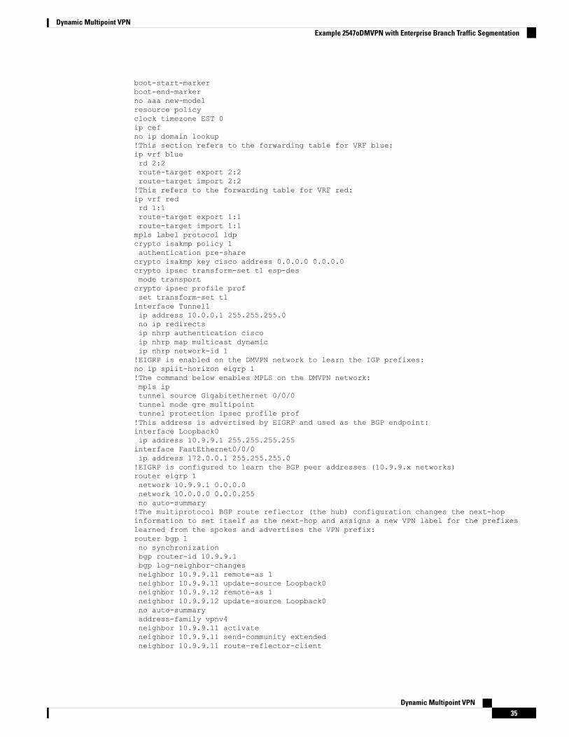
boot-start-markerboot-end-markerno aaa new-modelresource policyclock timezone EST 0ip cefno ip domain lookup!This section refers to the forwarding table for VRF blue:ip vrf bluerd 2:2route-target export 2:2route-target import 2:2!This refers to the forwarding table for VRF red:ip vrf redrd 1:1route-target export 1:1route-target import 1:1mpls label protocol ldpcrypto isakmp policy 1authentication pre-sharecrypto isakmp key cisco address 0.0.0.0 0.0.0.0crypto ipsec transform-set t1 esp-desmode transportcrypto ipsec profile profset transform-set t1interface Tunnel1ip address 10.0.0.1 255.255.255.0no ip redirectsip nhrp authentication ciscoip nhrp map multicast dynamicip nhrp network-id 1!EIGRP is enabled on the DMVPN network to learn the IGP prefixes:no ip split-horizon eigrp 1!The command below enables MPLS on the DMVPN network:mpls iptunnel source Gigabitethernet 0/0/0tunnel mode gre multipointtunnel protection ipsec profile prof!This address is advertised by EIGRP and used as the BGP endpoint:interface Loopback0ip address 10.9.9.1 255.255.255.255interface FastEthernet0/0/0ip address 172.0.0.1 255.255.255.0!EIGRP is configured to learn the BGP peer addresses (10.9.9.x networks)router eigrp 1network 10.9.9.1 0.0.0.0network 10.0.0.0 0.0.0.255no auto-summary!The multiprotocol BGP route reflector (the hub) configuration changes the next-hopinformation to set itself as the next-hop and assigns a new VPN label for the prefixeslearned from the spokes and advertises the VPN prefix:router bgp 1no synchronizationbgp router-id 10.9.9.1bgp log-neighbor-changesneighbor 10.9.9.11 remote-as 1neighbor 10.9.9.11 update-source Loopback0neighbor 10.9.9.12 remote-as 1neighbor 10.9.9.12 update-source Loopback0no auto-summaryaddress-family vpnv4neighbor 10.9.9.11 activateneighbor 10.9.9.11 send-community extendedneighbor 10.9.9.11 route-reflector-client
Dynamic Multipoint VPN35
Dynamic Multipoint VPNExample 2547oDMVPN with Enterprise Branch Traffic Segmentation
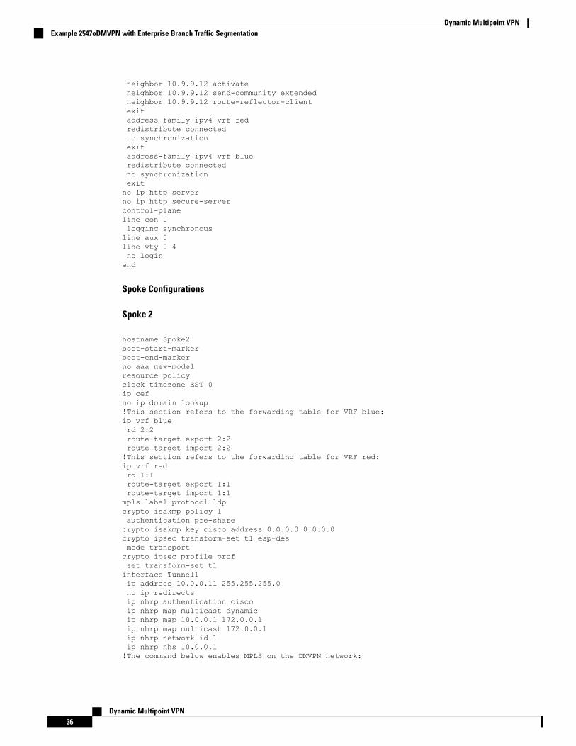
neighbor 10.9.9.12 activateneighbor 10.9.9.12 send-community extendedneighbor 10.9.9.12 route-reflector-clientexitaddress-family ipv4 vrf redredistribute connectedno synchronizationexitaddress-family ipv4 vrf blueredistribute connectedno synchronizationexitno ip http serverno ip http secure-servercontrol-planeline con 0logging synchronousline aux 0line vty 0 4no loginend
Spoke Configurations
Spoke 2
hostname Spoke2boot-start-markerboot-end-markerno aaa new-modelresource policyclock timezone EST 0ip cefno ip domain lookup!This section refers to the forwarding table for VRF blue:ip vrf bluerd 2:2route-target export 2:2route-target import 2:2!This section refers to the forwarding table for VRF red:ip vrf redrd 1:1route-target export 1:1route-target import 1:1mpls label protocol ldpcrypto isakmp policy 1authentication pre-sharecrypto isakmp key cisco address 0.0.0.0 0.0.0.0crypto ipsec transform-set t1 esp-desmode transportcrypto ipsec profile profset transform-set t1interface Tunnel1ip address 10.0.0.11 255.255.255.0no ip redirectsip nhrp authentication ciscoip nhrp map multicast dynamicip nhrp map 10.0.0.1 172.0.0.1ip nhrp map multicast 172.0.0.1ip nhrp network-id 1ip nhrp nhs 10.0.0.1!The command below enables MPLS on the DMVPN network:
Dynamic Multipoint VPN36
Dynamic Multipoint VPNExample 2547oDMVPN with Enterprise Branch Traffic Segmentation
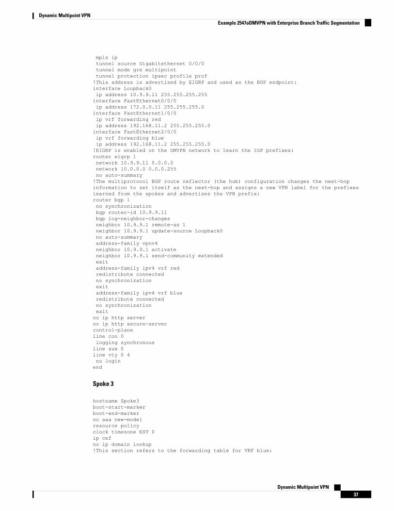
mpls iptunnel source Gigabitethernet 0/0/0tunnel mode gre multipointtunnel protection ipsec profile prof!This address is advertised by EIGRP and used as the BGP endpoint:interface Loopback0ip address 10.9.9.11 255.255.255.255interface FastEthernet0/0/0ip address 172.0.0.11 255.255.255.0interface FastEthernet1/0/0ip vrf forwarding redip address 192.168.11.2 255.255.255.0interface FastEthernet2/0/0ip vrf forwarding blueip address 192.168.11.2 255.255.255.0!EIGRP is enabled on the DMVPN network to learn the IGP prefixes:router eigrp 1network 10.9.9.11 0.0.0.0network 10.0.0.0 0.0.0.255no auto-summary!The multiprotocol BGP route reflector (the hub) configuration changes the next-hopinformation to set itself as the next-hop and assigns a new VPN label for the prefixeslearned from the spokes and advertises the VPN prefix:router bgp 1no synchronizationbgp router-id 10.9.9.11bgp log-neighbor-changesneighbor 10.9.9.1 remote-as 1neighbor 10.9.9.1 update-source Loopback0no auto-summaryaddress-family vpnv4neighbor 10.9.9.1 activateneighbor 10.9.9.1 send-community extendedexitaddress-family ipv4 vrf redredistribute connectedno synchronizationexitaddress-family ipv4 vrf blueredistribute connectedno synchronizationexitno ip http serverno ip http secure-servercontrol-planeline con 0logging synchronousline aux 0line vty 0 4no loginend
Spoke 3
hostname Spoke3boot-start-markerboot-end-markerno aaa new-modelresource policyclock timezone EST 0ip cefno ip domain lookup!This section refers to the forwarding table for VRF blue:
Dynamic Multipoint VPN37
Dynamic Multipoint VPNExample 2547oDMVPN with Enterprise Branch Traffic Segmentation
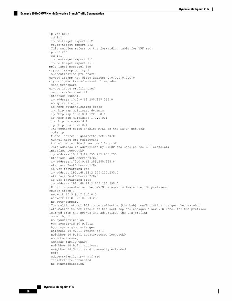
ip vrf bluerd 2:2route-target export 2:2route-target import 2:2!This section refers to the forwarding table for VRF red:ip vrf redrd 1:1route-target export 1:1route-target import 1:1mpls label protocol ldpcrypto isakmp policy 1authentication pre-sharecrypto isakmp key cisco address 0.0.0.0 0.0.0.0crypto ipsec transform-set t1 esp-desmode transportcrypto ipsec profile profset transform-set t1interface Tunnel1ip address 10.0.0.12 255.255.255.0no ip redirectsip nhrp authentication ciscoip nhrp map multicast dynamicip nhrp map 10.0.0.1 172.0.0.1ip nhrp map multicast 172.0.0.1ip nhrp network-id 1ip nhrp nhs 10.0.0.1!The command below enables MPLS on the DMVPN network:mpls iptunnel source Gigabitethernet 0/0/0tunnel mode gre multipointtunnel protection ipsec profile prof!This address is advertised by EIGRP and used as the BGP endpoint:interface Loopback0ip address 10.9.9.12 255.255.255.255interface FastEthernet0/0/0ip address 172.0.0.12 255.255.255.0interface FastEthernet1/0/0ip vrf forwarding redip address 192.168.12.2 255.255.255.0interface FastEthernet2/0/0ip vrf forwarding blueip address 192.168.12.2 255.255.255.0!EIGRP is enabled on the DMVPN network to learn the IGP prefixes:router eigrp 1network 10.9.9.12 0.0.0.0network 10.0.0.0 0.0.0.255no auto-summary!The multiprotocol BGP route reflector (the hub) configuration changes the next-hopinformation to set itself as the next-hop and assigns a new VPN label for the prefixeslearned from the spokes and advertises the VPN prefix:router bgp 1no synchronizationbgp router-id 10.9.9.12bgp log-neighbor-changesneighbor 10.9.9.1 remote-as 1neighbor 10.9.9.1 update-source Loopback0no auto-summaryaddress-family vpnv4neighbor 10.9.9.1 activateneighbor 10.9.9.1 send-community extendedexitaddress-family ipv4 vrf redredistribute connectedno synchronization
Dynamic Multipoint VPN38
Dynamic Multipoint VPNExample 2547oDMVPN with Enterprise Branch Traffic Segmentation
exitaddress-family ipv4 vrf blueredistribute connectedno synchronizationexitno ip http serverno ip http secure-servercontrol-planeline con 0logging synchronousline aux 0line vty 0 4no loginend
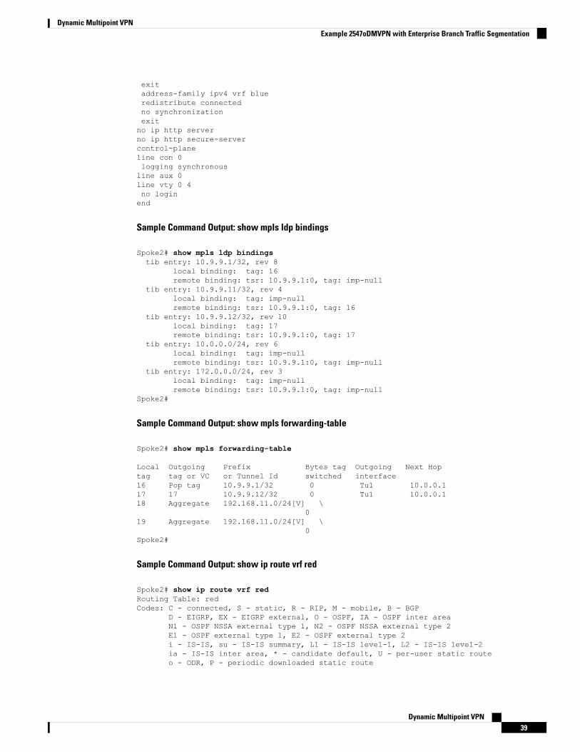
Sample Command Output: show mpls ldp bindings
Spoke2# show mpls ldp bindingstib entry: 10.9.9.1/32, rev 8
local binding: tag: 16remote binding: tsr: 10.9.9.1:0, tag: imp-null
tib entry: 10.9.9.11/32, rev 4local binding: tag: imp-nullremote binding: tsr: 10.9.9.1:0, tag: 16
tib entry: 10.9.9.12/32, rev 10local binding: tag: 17remote binding: tsr: 10.9.9.1:0, tag: 17
tib entry: 10.0.0.0/24, rev 6local binding: tag: imp-nullremote binding: tsr: 10.9.9.1:0, tag: imp-null
tib entry: 172.0.0.0/24, rev 3local binding: tag: imp-nullremote binding: tsr: 10.9.9.1:0, tag: imp-null
Spoke2#
Sample Command Output: show mpls forwarding-table
Spoke2# show mpls forwarding-table
Local Outgoing Prefix Bytes tag Outgoing Next Hoptag tag or VC or Tunnel Id switched interface16 Pop tag 10.9.9.1/32 0 Tu1 10.0.0.117 17 10.9.9.12/32 0 Tu1 10.0.0.118 Aggregate 192.168.11.0/24[V] \
019 Aggregate 192.168.11.0/24[V] \
0Spoke2#
Sample Command Output: show ip route vrf red
Spoke2# show ip route vrf redRouting Table: redCodes: C - connected, S - static, R - RIP, M - mobile, B - BGP
D - EIGRP, EX - EIGRP external, O - OSPF, IA - OSPF inter areaN1 - OSPF NSSA external type 1, N2 - OSPF NSSA external type 2E1 - OSPF external type 1, E2 - OSPF external type 2i - IS-IS, su - IS-IS summary, L1 - IS-IS level-1, L2 - IS-IS level-2ia - IS-IS inter area, * - candidate default, U - per-user static routeo - ODR, P - periodic downloaded static route
Dynamic Multipoint VPN39
Dynamic Multipoint VPNExample 2547oDMVPN with Enterprise Branch Traffic Segmentation
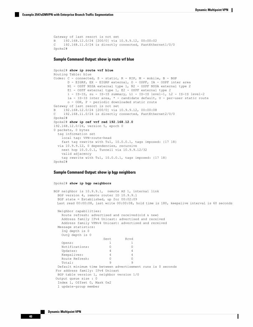
Gateway of last resort is not setB 192.168.12.0/24 [200/0] via 10.9.9.12, 00:00:02C 192.168.11.0/24 is directly connected, FastEthernet1/0/0Spoke2#
Sample Command Output: show ip route vrf blue
Spoke2# show ip route vrf blueRouting Table: blueCodes: C - connected, S - static, R - RIP, M - mobile, B - BGP
D - EIGRP, EX - EIGRP external, O - OSPF, IA - OSPF inter areaN1 - OSPF NSSA external type 1, N2 - OSPF NSSA external type 2E1 - OSPF external type 1, E2 - OSPF external type 2i - IS-IS, su - IS-IS summary, L1 - IS-IS level-1, L2 - IS-IS level-2ia - IS-IS inter area, * - candidate default, U - per-user static routeo - ODR, P - periodic downloaded static route
Gateway of last resort is not setB 192.168.12.0/24 [200/0] via 10.9.9.12, 00:00:08C 192.168.11.0/24 is directly connected, FastEthernet2/0/0Spoke2#Spoke2# show ip cef vrf red 192.168.12.0192.168.12.0/24, version 5, epoch 00 packets, 0 bytestag information setlocal tag: VPN-route-headfast tag rewrite with Tu1, 10.0.0.1, tags imposed: {17 18}
via 10.9.9.12, 0 dependencies, recursivenext hop 10.0.0.1, Tunnel1 via 10.9.9.12/32valid adjacencytag rewrite with Tu1, 10.0.0.1, tags imposed: {17 18}
Spoke2#
Sample Command Output: show ip bgp neighbors
Spoke2# show ip bgp neighbors
BGP neighbor is 10.9.9.1, remote AS 1, internal linkBGP version 4, remote router ID 10.9.9.1BGP state = Established, up for 00:02:09Last read 00:00:08, last write 00:00:08, hold time is 180, keepalive interval is 60 seconds
Neighbor capabilities:Route refresh: advertised and received(old & new)Address family IPv4 Unicast: advertised and receivedAddress family VPNv4 Unicast: advertised and received
Message statistics:InQ depth is 0OutQ depth is 0
Sent RcvdOpens: 1 1Notifications: 0 0Updates: 4 4Keepalives: 4 4Route Refresh: 0 0Total: 9 9
Default minimum time between advertisement runs is 0 secondsFor address family: IPv4 UnicastBGP table version 1, neighbor version 1/0Output queue size : 0Index 1, Offset 0, Mask 0x21 update-group member
Dynamic Multipoint VPN40
Dynamic Multipoint VPNExample 2547oDMVPN with Enterprise Branch Traffic Segmentation

Sent RcvdPrefix activity: ---- ----Prefixes Current: 0 0Prefixes Total: 0 0Implicit Withdraw: 0 0Explicit Withdraw: 0 0Used as bestpath: n/a 0Used as multipath: n/a 0
Outbound InboundLocal Policy Denied Prefixes: -------- -------Total: 0 0
Number of NLRIs in the update sent: max 0, min 0For address family: VPNv4 UnicastBGP table version 9, neighbor version 9/0Output queue size : 0Index 1, Offset 0, Mask 0x21 update-group member
Sent RcvdPrefix activity: ---- ----Prefixes Current: 2 2 (Consumes 136 bytes)Prefixes Total: 4 2Implicit Withdraw: 2 0Explicit Withdraw: 0 0Used as bestpath: n/a 2Used as multipath: n/a 0
Outbound InboundLocal Policy Denied Prefixes: -------- -------ORIGINATOR loop: n/a 2Bestpath from this peer: 4 n/aTotal: 4 2
Number of NLRIs in the update sent: max 1, min 1Connections established 1; dropped 0Last reset never
Connection state is ESTAB, I/O status: 1, unread input bytes: 0Connection is ECN DisabledLocal host: 10.9.9.11, Local port: 179Foreign host: 10.9.9.1, Foreign port: 12365Enqueued packets for retransmit: 0, input: 0 mis-ordered: 0 (0 bytes)Event Timers (current time is 0x2D0F0):Timer Starts Wakeups NextRetrans 6 0 0x0TimeWait 0 0 0x0AckHold 7 3 0x0SendWnd 0 0 0x0KeepAlive 0 0 0x0GiveUp 0 0 0x0PmtuAger 0 0 0x0DeadWait 0 0 0x0iss: 3328307266 snduna: 3328307756 sndnxt: 3328307756 sndwnd: 15895irs: 4023050141 rcvnxt: 4023050687 rcvwnd: 16384 delrcvwnd: 0SRTT: 165 ms, RTTO: 1457 ms, RTV: 1292 ms, KRTT: 0 msminRTT: 0 ms, maxRTT: 300 ms, ACK hold: 200 msFlags: passive open, nagle, gen tcbsIP Precedence value : 6Datagrams (max data segment is 536 bytes):Rcvd: 13 (out of order: 0), with data: 7, total data bytes: 545Sent: 11 (retransmit: 0, fastretransmit: 0, partialack: 0, Second Congestion: 0), with data:6, total data bytes: 489Spoke2#
Dynamic Multipoint VPN41
Dynamic Multipoint VPNExample 2547oDMVPN with Enterprise Branch Traffic Segmentation
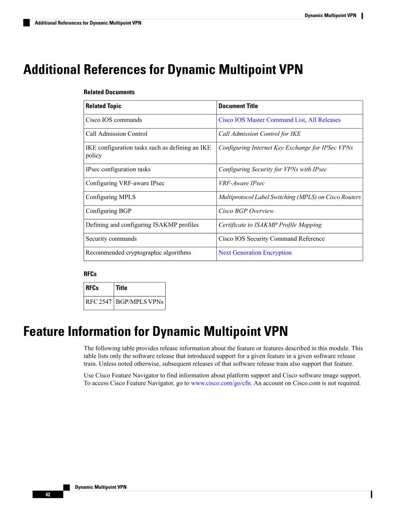
Additional References for Dynamic Multipoint VPNRelated Documents
Document TitleRelated Topic
Cisco IOS Master Command List, All ReleasesCisco IOS commands
Call Admission Control for IKECall Admission Control
Configuring Internet Key Exchange for IPSec VPNsIKE configuration tasks such as defining an IKEpolicy
Configuring Security for VPNs with IPsecIPsec configuration tasks
VRF-Aware IPsecConfiguring VRF-aware IPsec
Multiprotocol Label Switching (MPLS) on Cisco RoutersConfiguring MPLS
Cisco BGP OverviewConfiguring BGP
Certificate to ISAKMP Profile MappingDefining and configuring ISAKMP profiles
Cisco IOS Security Command ReferenceSecurity commands
Next Generation EncryptionRecommended cryptographic algorithms
RFCs
TitleRFCs
BGP/MPLSVPNsRFC2547
Feature Information for Dynamic Multipoint VPNThe following table provides release information about the feature or features described in this module. Thistable lists only the software release that introduced support for a given feature in a given software releasetrain. Unless noted otherwise, subsequent releases of that software release train also support that feature.
Use Cisco Feature Navigator to find information about platform support and Cisco software image support.To access Cisco Feature Navigator, go to www.cisco.com/go/cfn. An account on Cisco.com is not required.
Dynamic Multipoint VPN42
Dynamic Multipoint VPNAdditional References for Dynamic Multipoint VPN
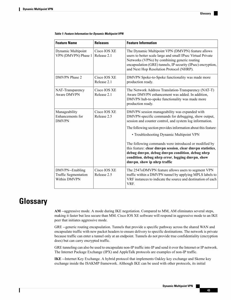
Table 1: Feature Information for Dynamic Multipoint VPN
Feature InformationReleasesFeature Name
The Dynamic Multipoint VPN (DMVPN) feature allowsusers to better scale large and small IPsec Virtual PrivateNetworks (VPNs) by combining generic routingencapsulation (GRE) tunnels, IP security (IPsec) encryption,and Next Hop Resolution Protocol (NHRP).
Cisco IOS XERelease 2.1
Dynamic MultipointVPN (DMVPN) Phase 1
DMVPN Spoke-to-Spoke functionality was made moreproduction ready.
Cisco IOS XERelease 2.1
DMVPN Phase 2
The Network Address Translation-Transparency (NAT-T)Aware DMVPN enhancement was added. In addition,DMVPN hub-to-spoke functionality was made moreproduction ready.
Cisco IOS XERelease 2.1
NAT-TransparencyAware DMVPN
DMVPN session manageability was expanded withDMVPN-specific commands for debugging, show output,session and counter control, and system log information.
The following section provides information about this feature:
• Troubleshooting Dynamic Multipoint VPN
The following commands were introduced or modified bythis feature: clear dmvpn session, clear dmvpn statistics,debug dmvpn, debug dmvpn condition, debug nhrpcondition, debug nhrp error, logging dmvpn, showdmvpn, show ip nhrp traffic
Cisco IOS XERelease 2.5
ManageabilityEnhancements forDMVPN
The 2547oDMVPN feature allows users to segment VPNtraffic within a DMVPN tunnel by applying MPLS labels toVRF instances to indicate the source and destination of eachVRF.
Cisco IOS XERelease 2.5
DMVPN--EnablingTraffic SegmentationWithin DMVPN
GlossaryAM --aggressive mode. A mode during IKE negotiation. Compared to MM, AM eliminates several steps,making it faster but less secure than MM. Cisco IOS XE software will respond in aggressive mode to an IKEpeer that initiates aggressive mode.
GRE --generic routing encapsulation. Tunnels that provide a specific pathway across the shared WAN andencapsulate traffic with new packet headers to ensure delivery to specific destinations. The network is privatebecause traffic can enter a tunnel only at an endpoint. Tunnels do not provide true confidentiality (encryptiondoes) but can carry encrypted traffic.
GRE tunneling can also be used to encapsulate non-IP traffic into IP and send it over the Internet or IP network.The Internet Package Exchange (IPX) and AppleTalk protocols are examples of non-IP traffic.
IKE --Internet Key Exchange. A hybrid protocol that implements Oakley key exchange and Skeme keyexchange inside the ISAKMP framework. Although IKE can be used with other protocols, its initial
Dynamic Multipoint VPN43
Dynamic Multipoint VPNGlossary
implementation is with IPsec. IKE provides authentication of the IPsec peers, negotiates IPsec keys, andnegotiates IPsec security associations.
IPsec --IP security. A framework of open standards developed by the Internet Engineering Task Force (IETF).IPsec provides security for transmission of sensitive information over unprotected networks such as theInternet. IPsec acts at the network layer, protecting and authenticating IP packets between participating IPsecdevices (“peers”), such as Cisco routers.
ISAKMP--Internet Security Association Key Management Protocol. A protocol framework that definespayload formats, the mechanics of implementing a key exchange protocol, and the negotiation of a securityassociation.
MM--main mode.Mode that is slower than aggressive mode but more secure andmore flexible than aggressivemode because it can offer an IKE peer more security proposals. The default action for IKE authentication(rsa-sig, rsa-encr, or preshared) is to initiate main mode.
NHRP --Next Hop Resolution Protocol. Routers, access servers, and hosts can use NHRP to discover theaddresses of other routers and hosts connected to an NBMA network.
The Cisco implementation of NHRP supports the IETF draft version 11 of NBMA Next Hop ResolutionProtocol (NHRP).
The Cisco implementation of NHRP supports IP Version 4, Internet Packet Exchange (IPX) network layers,and, at the link layer, ATM, FastEthernet, SMDS, andmultipoint tunnel networks. Although NHRP is availableon FastEthernet, NHRP need not be implemented over FastEthernet media because FastEthernet is capableof broadcasting. FastEthernet support is unnecessary (and not provided) for IPX.
PFS--perfect forward secrecy. A cryptographic characteristic associated with a derived shared secret value.With PFS, if one key is compromised, previous and subsequent keys are not compromised, because subsequentkeys are not derived from previous keys.
SA--security association. Describes how two or more entities will utilize security services to communicatesecurely. For example, an IPsec SA defines the encryption algorithm (if used), the authentication algorithm,and the shared session key to be used during the IPsec connection.
Both IPsec and IKE require and use SAs to identify the parameters of their connections. IKE can negotiateand establish its own SA. The IPsec SA is established either by IKE or by manual user configuration.
transform--The list of operations done on a data flow to provide data authentication, data confidentiality, anddata compression. For example, one transform is the ESP protocol with the HMAC-MD5 authenticationalgorithm; another transform is the AH protocol with the 56-bit DES encryption algorithm and the ESP protocolwith the HMAC-SHA authentication algorithm.
VPN--Virtual Private Network. A framework that consists of multiple peers transmitting private data securelyto one another over an otherwise public infrastructure. In this framework, inbound and outbound networktraffic is protected using protocols that tunnel and encrypt all data. This framework permits networks to extendbeyond their local topology, while remote users are provided with the appearance and functionality of a directnetwork connection.
Dynamic Multipoint VPN44
Dynamic Multipoint VPNGlossary


![Point-to-Multipoint and Multipoint-to-Multipoint · PDF filedefined by IEEE 802.1Qay [2] is representative carrier Ethernet . Abstract — We have implemented point-to-multipoint (PtMP)](https://img.pdfslide.net/doc/110x75/5a75c0147f8b9a4b538cb6cd/point-to-multipoint-and-multipoint-to-multipoint-defined-by-ieee-8021qay.jpg)
![Cisco Integrated Services Router der Serie 890 - CANCOMmedia.cancom.de/attachments/e/6/e6062395-503f-d24a-b705-557336f... · Encryption Standard [AES]), Dynamic Multipoint VPN [DMVPN],](https://img.pdfslide.net/doc/110x75/5a9db49b7f8b9a85318ba8ea/cisco-integrated-services-router-der-serie-890-standard-aes-dynamic-multipoint.jpg)