Embed Size (px)
Citation preview

RESEARCH AND EDUCATION
aGraduate stubProfessor, DcAssistant PrdAssociate Pr
412
Dynamic nature of abutment screw retightening:Finite element study of the effect of retightening on
the settling effect
Haddad Arabi Bulaqi, MSc,a Mahmoud Mousavi Mashhadi, PhD,b Hamed Safari, DDS, MS,cMohammad Mahdi Samandari, MSc,a and Farideh Geramipanah, DDS, MSd
ABSTRACTStatement of problem. A fundamental problem in fully understanding the dynamic nature ofscrew loosening is lack of recognition of the entire process of screw tightening and retightening.
Purpose. The purpose of this study was to explain the dynamic nature of abutment screwretightening by using finite element methods to investigate the effect of the coefficient of frictionand retightening on the settling effect.
Material and methods. Precise computer models were designed of a Straumann dental implant, adirectly attached crown, an abutment screw, and the bone surrounding the implant. All threadedinterfaces were designed with a spiral thread helix with a specific coefficient of static and kineticfriction, and the surfaces were characterized as fine, regular, and rough. Abaqus software was usedfor dynamic simulation, which involved applying rotational displacement to the abutment screwand torque controlling during the steps of tightening, relaxation, retightening, and second relax-ation and at different coefficients of friction. The obtained torque and preload values werecompared to the predicted values.
Results. When surfaces changed from fine to rough, the remaining torque and preload decreased,and the settling effect increased. Upon retightening, the remaining torque and preload increased,and the settling effect also decreased.
Conclusions. The reduction of the coefficient of friction contributes to increases in the preload anddecreases in the settling effect. Retightening reduced the settling effect and had an insignificanteffect on the preload. At high coefficients of friction, the retightening effect was intensified. (JProsthet Dent 2015;113:412-419)
A dental implant is a pros-thetic replacement for a miss-ing tooth and consists of animplant, an abutment, and anoverlying crown or other den-tal prosthesis. The most com-mon method to secure theabutment to the implant isa retaining screw. Some com-mon complications associatedwith this type of retainingsystem are screw looseningand fracture,1-3 particularly withsingle-tooth restorations4,5 andexternal hexagonal connectionsystems.6,7 The prevalence ofscrew loosening is about 38%in external hexagonal sys-tems.8,9 In fact, 26% of goldprosthesis-retaining screws and43% of abutment screws loosenduring thefirst year of service.8,10
Two methods are used to prevent screw loosening:sufficient preload11-13 and antirotational resistanceform.14,15 Improvements in the design of the implant-abutment junction have led to a significant reduction inthe incidence of screw loosening. These modificationsinvolve the addition of antirotational designs. Examplesinclude larger external hexagons, frictional fit abutments,
dent, Department of Mechanical Engineering, School of Mechanics, Univepartment of Mechanical Engineering, School of Mechanics, University ofofessor, Department of Periodontics, School of Dentistry, Qom University oofessor, Implant Research Center, Department of Prosthodontics, School
including taper integrated screwed-in abutments andtapered interference fit connections, and the Splineimplant.7,16
Previous research has demonstrated that preloadcreates a strong compressive clamping force that keepsthe different components tightly connected.12,17 Thepreload and clamping force are equal but in opposite
ersity of Tehran, Tehran, Iran.Tehran, Tehran, Iran.f Medical Sciences, Qom, Iran.of Dentistry, Tehran University of Medical Sciences, Tehran, Iran.
THE JOURNAL OF PROSTHETIC DENTISTRY

Wrenchinterface
Conicalinterface
Threadinterface
Thread-conicalregion
Conical-wrenchregion
D
d
dm
L
2α
β
Figure 1. Geometric parameters of implant complex; d=2.015 mm,D=2.6 mm, a=2b=p/6 radian, L=0.4 mm, dm=1.66 mm.
Clinical ImplicationsA full understanding of the mechanism of screwloosening can help clinicians to implement appro-priate avoidance measures. The settling effect playsan important role in screw loosening. Retighteningthe screw a few minutes after the initial tighteningcan reduce this effect.
May 2015 413
directions. Preload is defined as the tensile force built inthe axial axis of the screw; this tensile force is distributedin a nonlinear manner as a result of screw elongation.11,18
Preload is dependent on the applied torque, thecomponent material, the screw head and thread design,and the coefficient of friction for the contact surfaces.18,19
The coefficient of friction can be reduced with lubricationand an increased rate of tightening; in contrast, it can beincreased by increasing material hardness and surfaceroughness.20
The uniform pressure theory can be used to calculatethe sliding friction of the conical interface, which issimilar to the cone clutch. According to this theory,the pressure distribution is uniform in the radial direc-tion of the conical surface. Budynas and Nisbett21 pro-posed Equation (1) to determine the frictional resistanceof the thread torque ðTthÞ and Equation (2) to determinethe conical torque ðTcÞ. Additionally, wrench torque(Tw, Eq. (3)) is the sum of the thread and conicaltorques.
Tth=dm2×L+ðm×p×dm×sec aÞðp×dmÞ-ðm×L×sec aÞ×F=Kth×F (1)
Tc=m
3 sin b×D3-d3
D2-d2×F=Kc×F (2)
Tw=Tth+Tc=½Kth+Kc�×F (3)
Tth-w=TthTw
=Kth
Kth+Kc(4)
P=Tw
Kth+Kc=
35Kth+Kc
; (5)
where Tth-w represents the ratio of thread torque towrench torque. In addition, F is the preload created in thescrew; P is the preload at the recommended torque of 35Ncm; m is the coefficient of friction in the threads and
Bulaqi et al
conical head; d is the inner head friction diameter; D isthe outer head friction diameter; b is the cone anglehead; a is the half angle of the thread; L the is pitchlength; and dm is the pitch diameter. The geometric pa-rameters are presented in Figure 1.
In a 6-year follow-up study, Haas et al22 showed thatthe use of high tightening torque could reduce the inci-dence of screw loosening. Stüker et al23 demonstratedthat generated preloads on gold screws using a drylubricant were 3 times greater than those on titaniumscrews.
Excessive bending at the screw joint and the settlingeffect, otherwise known as embedment relaxation, alsocontribute to screw loosening.7,11,12 The settling effect isbased on the fact that no surface is completely smooth.This microroughness prevents the 2 surfaces from fullycontacting each other. Once the initial torque is applied,the rough spots are the only surfaces that remain incontact. However, these contact spots flatten as a resultof the highly concentrated pressure. Consequently,micromovement occurs in the opposite direction of theelongation axis of the screw, thereby resulting in a loss ofpreload.24 This loss can be as high as 2% to 10%.25 The 3major parameters that influence the settling effect areinitial surface roughness, surface hardness, and magni-tude of preload.11 Winkler et al24 concluded that in orderto reduce the settling effect, the abutment screw shouldbe retightened 10 minutes after the initial torque isapplied. As previously mentioned, roughness and hard-ness are 2 parameters that influence the coefficient offriction.20 Therefore, an increase in the coefficient offriction and preload will likely lead to an increase in thesettling effect.11
Regarding the implant-abutment interface design,Aboyoussef et al7 observed that abutments that had animproved resistance design reduced the incidence ofscrew loosening due to an increase in the moment arm,which is defined as the length from the center of rotationof the screw interface to the crown/abutment interface.However, variation in the coefficient of friction can
THE JOURNAL OF PROSTHETIC DENTISTRY

414 Volume 113 Issue 5
influence the mechanical behavior of screw tightening. Ina study conducted by Tzenakis et al,26 salivary contami-nation and repeated retightening of the screw caused ahigher preload as a result of a reduction in friction.Likewise, Hagiwara27 observed that friction was reducedwith repeated tightening of the screw compared to asingle tightening of the screw. Farina et al28 evaluatedtightening techniques used in an implant-supporteddenture set and concluded that the use of the retorqueapplication significantly increased joint stability.
Another factor that must be considered is the mech-anism of preload loosening over time. Cantwell andHobkirk29 observed that the greatest and most rapidpreload changes occur in the first 2 seconds. They alsofound that the decrease in preload is an exponentialfunction over the long term. Indeed, the mean preloadloss over the first 15 hours was 24.9%; however, 29.5% ofthis loss occurred within the first 2 seconds, and 40.2%occurred within the first 10 seconds.
Several in vitro and in vivo studies have attempted toexplain the mechanisms involved in the screw-tighteningprocedure. However, a detailed description of thedifferent steps involved in this procedure (tightening,relaxation, and retightening) is still lacking, probablybecause of the complex and unconventional experimentalprocedure required to elucidate this information. Thefinite element method offers the ability to gather andstudy elaborate data that cannot be obtained by usingconventional methods. In this study, finite elementmethods were used to explain the dynamic nature ofscrew retightening and the effect of the coefficient offriction and retightening on the settling effect throughoutthe different steps associated with tightening the abut-ment screw in a dental implant.
MATERIAL AND METHODS
For a complete simulation with proper boundary condi-tions, a mandibular posterior section was modeled byusing cone beam computed tomography, and CATIA V5R19 (Dassault Systèmes) software was used to createcomputer-aided design (CAD) files. Note that thismandibular section contained a central trabecular coresurrounded by a dense cortical layer.
The geometry models of a Straumann implant (SLA043.031S; Institute Straumann), a directly attached crown(048.642, RN SynOcta gold abutment), and an abutmentscrew (048.356, SynOcta basal screw) were constructedwith a projection microscope and SOLIDWORKS (Das-sault Systèmes) software. The diameter of the implantwas 4.1 mm, and the length was 8 mm. In order tosimulate the process of screw tightening, preload crea-tion, and osseointegration, the exact geometry of theabutment screw and implant threads were modeled. Theouter surfaces of the implant and abutment screw were
THE JOURNAL OF PROSTHETIC DENTISTRY
geometrically modeled with a continuous spiral threadedhelix, and the inner surfaces of the implant and bonebore were geometrically modeled with a continuousspiral threaded bore. The thread pitch of the abutmentscrew was 0.4 mm, and the thread pitch of the implantwas 1.25 mm.
All material properties were considered to be isotropicand homogeneous. The mechanical behavior of theimplant component materials was assumed to be bothelastic and plastic. Also, the mechanical properties of thesurrounding bone were assumed to be linear and elastic.Table 1 presents the mechanical properties of the mate-rials used.30
The coulomb friction and penalty method were usedto model the dry friction contact for the abutment screw,abutment, and fixture. In order to compare the qualitativeand quantitative effects of the surface character, 3different types of friction conditions were considered.Specifically, 3 coefficients of kinetic friction ðmkÞ, 0.12 forfine surfaces, 0.16 for regular surfaces, and 0.20 for roughsurfaces, were used for the tightening and retighteningsteps, and 3 coefficients of static friction ðmsÞ, 0.16 for finesurfaces, 0.20 for regular surfaces, and 0.24 for roughsurfaces, were used for the relaxation steps.12,31 Notethat the coefficient of kinetic friction is always lower thanthat of static friction. The implant-bone interface wasassumed to be completely osseointegrated; therefore, thecontact of implant-bone interface was defined as “tie.”After assembling the implant complex inside the bone,the screw was placed in the “snug-tight” condition, asshown in Figure 2.
For the explicit dynamic simulation, the CAD modelswere transferred to the ABAQUS 6.11 (Dassault Sys-tèmes Simulia Corp) software. The explicit element li-brary and the free meshing technique with lineargeometric order were used to generate the tetrahedralelements. Tangential behavior and contact interface withspecific coefficients of friction were defined for thereciprocal contacting surfaces. Table 2 lists the number ofelements for the model parts, and Figure 3 shows themeshed models for the fixture, abutment screw, andabutment.
As the abutment screw rotates around its axis onecomplete turn, it displaces one screw pitch inside thethread of the fixture. The preload is induced by theresistance against the axial displacement and causeselongation in the abutment screw. The simulation wasperformed in 4 main steps. In step 1 (tightening [t]),using an angular velocity of 0.5 radian per second, thewrench turned the abutment screw enough to achieve atorque of 35 Ncm. In step 2 (the first relaxation [re1]), thewrench was removed for 2 seconds so that the initialrelaxation could occur. In step 3 (retightening [rt]), thewrench retightened the abutment screw with an angularvelocity of 0.5 radian per second until a torque of 35 Ncm
Bulaqi et al

Table 2.Number of tetrahedral elements for each part in model
Part No. of Elements
Implant (fixture) 78 774
Abutment screw 32 303
Abutment 24 925
Cortical bone 39 700
Trabecular bone 55 947
Figure 3. Finite element models. A, Fixture. B, Abutment screw. C,Abutment.
Abutment
7 µm
Angular displacement
Axis of turn
10 µm
Abutment screwFixtureCortical boneTrabecular bone
Figure 2. Three-dimensional models of structure. Depicted gaps are inmicrometers.
Table 1.Mechanical properties of model components
MaterialComponent
YoungModulus(GPa)
PoissonRatio
Density(g/cm3)
UltimateStrength(MPa)
Elongation(%)
Goldabutment*
136 0.37 17.5 765 10 min
Titaniumgrade 4*
110 0.34 4.5 550 15 min
Corticalbone30
13.70 0.3 3 190 2 max
Trabecularbone30
1.37 0.3 3 10 2 max
*Manufacturer’s specifications.
May 2015 415
was regained. In step 4 (the second relaxation [re2]), thewrench was completely removed, and the second relax-ation occurred over the next 2 seconds.
The relationships among the wrench torque, theconical torque, the thread torque, and the preload wereassessed with respect to time for different coefficientsof friction. Additionally, linear regression was used toanalyze the conical torque, thread torque, and preloaddata in the second (Tre1c ,Tre1th ,P2) and fourth (Tre2c ,Tre2th ,P4)steps.
RESULTS
The balance of torques acting on the wrench, conical, andthread interfaces were evaluated in the 4 steps using freebody diagrams (Fig. 4). Figure 5 shows the values ofwrench torque, conical torque, thread torque, and pre-load with respect to time for the 4 steps at differentfriction coefficient values. The maximum created wrenchtorque in the first ðTtwÞ and third ðTrt2w Þ steps for all surfaceconditions was 35 Ncm. The values of the conical andthread torques were Ttc=26 and Ttth=9 Ncm in the firststep and Trt2c =25:77 and Trt2th =9:23 Ncm in the third stepðmk=0:12Þ.
Bulaqi et al
The wrench torque at the second ðTre1w Þ and fourthðTre2w Þ steps were totally dampened after a few vibrationsin these steps, and the value of the conical torque (Tre1c ,Tre2c ) and the thread torque (Tre1th ,Tre2th ) were equal inthe opposite directions. The values of the thread torquewere 7.96 Ncm in the second step and 8.18 Ncm in thefourth step ðms=0:16Þ. The amounts of wrench torque,conical torque, and thread torque in the 4 steps atthe various friction coefficient values are presented inTable 3.
The maximum values of the preload in the first stepðP1Þ were 504.1 N ðmk=0:12Þ, 393.1 N ðmk=0:16Þ, and319.9 N ðmk=0:20Þ. The values of the preload in the firstðP1Þ and third ðP3Þ steps and the relationship betweenthe preload loosening with respect to time in the secondðP2Þ and fourth ðP4Þ steps are presented in Table 4.Figure 6 shows the predicted and simulated values of theratio of thread torque to wrench torque and the preloadas a function of the friction coefficient. The values ofthese ratios and preload values are shown in Table 5.
DISCUSSION
Screw loosening is considered a major complicationassociated with dental implants.3 Changes in the factorsconsidered influential to the preload, such as the anti-rotational properties of the abutment, the settling effect,and functional loads, may play a fundamental role inscrew loosening. According to the mechanics of
THE JOURNAL OF PROSTHETIC DENTISTRY

20
0 1 2 3 4 5 6
Time (second)
Time (second)
Time (second)
100
-10
Wre
nch
torq
ue (N
cm)
-20-30
-40
(μk, μs) = (0.12, 0.16)(μk, μs) = (0.16, 0.20)(μk, μs) = (0.20, 0.24)
30
0 6
2010
0
Coni
cal t
orqu
e (N
cm)
-10-20
-30
0 1 2 3 4 5 6
10
8
6
Thre
ad to
rque
(Ncm
)
4
2
0
600500400
00
1 2
P2 = 504 - 3.03t P4 = 510.7 - 1.79t
3 4 5 6
300
Prel
oad
(N)
200100
step 1 step 2 step 3 step 4
step 1 step 2 step 3 step 4
Time (second)
step 1
1 2 3 4 5
step 2 step 3 step 4
A
B
C
DFigure 5. A, Changes in wrench torque ðTwÞ. B, Conical torque ðTcÞ. C,Thread torque ðTthÞ. D, Preload (P).
A
step 1Wrench interface
Conical interface
Axis of Turn
Thread interface
step 2stage 1 of step 3
stage 2 of step 3 step 4
B C D E
T tth
T tc
T tw
T re1c T rt1
c
T rt1w
T rt2c
T rt2w
T re2c
ϕre2th-wϕrt2
c-w
ϕrt2th-w
ϕre1th-w
ϕre1th-wϕt
c-w
ϕtth-w
T re1th T rt1
th T rt2th T re2
th
ϕre2th-cϕrt2
th-cϕtth-c ϕre1
th-c
ϕrt1th-c ϕ= +ε2
re1th-c
ε2
ε1
Figure 4. Free body diagrams of abutment screw show corresponding wrench torque ðTwÞ, conical torque ðTcÞ, and thread torque ðTthÞ. A, Duringtightening. B, First relaxation. C, D, Retightening. E, Second relaxation.
416 Volume 113 Issue 5
THE JOURNAL OF PROSTHETIC DENTISTRY
materials, if a shaft with the length L, shear modulus G;and a polar moment of inertia J is twisted by torque T, anangular twist of 4=ðT×LÞ=ðG×JÞ would be created. Also,note that the angular twist 4 is proportional to theapplied torque T.32
Two contact regions in the abutment screw aredefined as the thread-conical and conical-wrench regions(Fig. 1). By applying the rotational displacement to theabutment screw in the first step and regarding the fric-tional resistance at the conical ðTtcÞ and thread ðTtthÞ in-terfaces, the wrench torque ðTtwÞ is consequently createdat the wrench interface (Eq. (6), Fig. 4A).
The angular twist of 4tth-c at the thread-conical region
and 4tc-w at the conical-wrench region were created by
Ttth and Ttw. By choosing the thread interface as theorigin for the coordinates, the angular twist at theconical-thread region was 4t
th-c and at the wrench-thread region was 4t
th-c+4tc-w (Fig. 4A). By removing
the wrench in the second step, the angular twist 4tc-w
was also eliminated, and according to the equilibrationcondition, the thread torque ðTre1th Þ was counterbalancedby the conical torque ðTre1c Þ (Eq. (7), Fig. 4B). Because theconical portion of the abutment screw and the abutmentact as a wedge, the torsional resistance, Ttc, which iscreated by tightening, is restored as internal energy(preload), which attempts to push out the abutmentscrew. In the second step, the restored internal energy isreduced as a result of counterbalancing the magnitude ofresistance Tre1th while disregarding the negligible damping.The remaining torque ðTtc-Tre1th Þ is thus distributed at theconical interface.
The third step, retightening, comprised 2 substages.In the first substage, the screw head turns ε1 radian; notethat ε has a very small value. As a result, the remainingrestored energy ðTtc-Tre1th Þ is released at the conicalinterface and appears as the torsional torque Trt1c .This behavior indicates that the ε2 radian turn, whichoccurs at the conical interface, was in the same directionas ε1 such that ε2>ε1. Therefore, the torque at the wrenchinterface ðTrt1w Þ has a positive value and increases until
Bulaqi et al
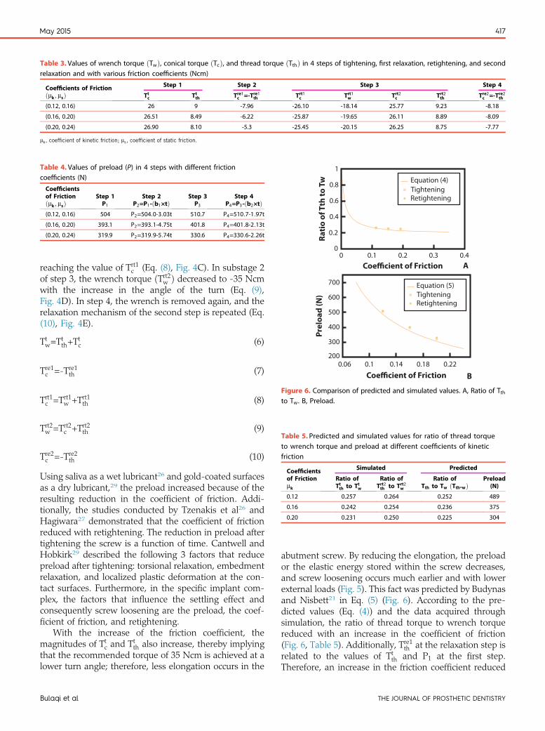
Table 3. Values of wrench torque ðTwÞ, conical torque ðTcÞ, and thread torque ðTthÞ in 4 steps of tightening, first relaxation, retightening, and secondrelaxation and with various friction coefficients (Ncm)
Coefficients of Frictionðmk ; msÞ
Step 1 Step 2 Step 3 Step 4
Ttc Ttth Tre1c =-Tre1th Trt1c Trt1w Trt2c Trt2th Tre2c =-Tre2th
(0.12, 0.16) 26 9 -7.96 -26.10 -18.14 25.77 9.23 -8.18
(0.16, 0.20) 26.51 8.49 -6.22 -25.87 -19.65 26.11 8.89 -8.09
(0.20, 0.24) 26.90 8.10 -5.3 -25.45 -20.15 26.25 8.75 -7.77
mk, coefficient of kinetic friction; ms, coefficient of static friction.
Table 4. Values of preload (P) in 4 steps with different frictioncoefficients (N)
Coefficientsof Frictionðmk ; msÞ
Step 1P1
Step 2P2=P1-ðb1×tÞ
Step 3P3
Step 4P4=P3-ðb2×tÞ
(0.12, 0.16) 504 P2=504:0-3:03t 510.7 P4=510:7-1:97t
(0.16, 0.20) 393.1 P2=393:1-4:75t 401.8 P4=401:8-2:13t
(0.20, 0.24) 319.9 P2=319:9-5:74t 330.6 P4=330:6-2:26t
00
0.2
0.4
0.6
0.8Equation (4)TighteningRetightening
Rati
o of
Tth
to T
w
1
0.1 0.2Coefficient of Friction
0.3 0.4A
700
600
500
400
300
200
Equation (5)TighteningRetightening
Prel
oad
(N)
May 2015 417
reaching the value of Trt1c (Eq. (8), Fig. 4C). In substage 2of step 3, the wrench torque ðTrt2w Þ decreased to -35 Ncmwith the increase in the angle of the turn (Eq. (9),Fig. 4D). In step 4, the wrench is removed again, and therelaxation mechanism of the second step is repeated (Eq.(10), Fig. 4E).
Ttw=Ttth+T
tc (6)
Coefficient of Friction0.06 0.1 0.14 0.18 0.22
B
Figure 6. Comparison of predicted and simulated values. A, Ratio of Tth
Tre1c =-Tre1th (7)
to Tw. B, Preload.
Trt1c =Trt1w +Trt1th (8)Table 5. Predicted and simulated values for ratio of thread torqueto wrench torque and preload at different coefficients of kinetic
Trt2w =Trt2c +Trt2th (9)
friction
Coefficientsof Frictionmk
Simulated Predicted
Ratio ofTtth to Ttw
Ratio ofTrt2th to Trt2w
Ratio ofTth to Tw ðTth-wÞ
Preload(N)
0.12 0.257 0.264 0.252 489
0.16 0.242 0.254 0.236 375
0.20 0.231 0.250 0.225 304
Tre2c =-Tre2th (10)
Using saliva as a wet lubricant26 and gold-coated surfacesas a dry lubricant,29 the preload increased because of theresulting reduction in the coefficient of friction. Addi-tionally, the studies conducted by Tzenakis et al26 andHagiwara27 demonstrated that the coefficient of frictionreduced with retightening. The reduction in preload aftertightening the screw is a function of time. Cantwell andHobkirk29 described the following 3 factors that reducepreload after tightening: torsional relaxation, embedmentrelaxation, and localized plastic deformation at the con-tact surfaces. Furthermore, in the specific implant com-plex, the factors that influence the settling effect andconsequently screw loosening are the preload, the coef-ficient of friction, and retightening.
With the increase of the friction coefficient, themagnitudes of Ttc and Ttth also increase, thereby implyingthat the recommended torque of 35 Ncm is achieved at alower turn angle; therefore, less elongation occurs in the
Bulaqi et al
abutment screw. By reducing the elongation, the preloador the elastic energy stored within the screw decreases,and screw loosening occurs much earlier and with lowerexternal loads (Fig. 5). This fact was predicted by Budynasand Nisbett21 in Eq. (5) (Fig. 6). According to the pre-dicted values (Eq. (4)) and the data acquired throughsimulation, the ratio of thread torque to wrench torquereduced with an increase in the coefficient of friction(Fig. 6, Table 5). Additionally, Tre1th at the relaxation step isrelated to the values of Ttth and P1 at the first step.Therefore, an increase in the friction coefficient reduced
THE JOURNAL OF PROSTHETIC DENTISTRY

418 Volume 113 Issue 5
the values of Ttth and P1; consequently, the magnitude ofTre1th was reduced. An increase in the friction coefficientresulted in a more significant decrease in Tre1th ; indicatingthat Ttth- Tre1th increased. Consequently, the rate of preloaddecrease b1 increased, and the settling effect intensified(Tables 3, 4). Additionally, the settling effect increasedthe incidence of the screw loosening rate.
As a result of the high contact pressure, the micro-roughness is smoothed, and the micromovement occur-ring in the opposite direction of the elongation leads to adecrease in the preload.24 The preload reduction in thefirst 2 seconds after the first tightening can be assumed tobe approximately linear, even though the preload de-creases as an exponential function over the long term.29
Furthermore, the abrasion of the tips found in areas ofmicroroughness reduces the coefficient of friction bydecreasing the surface roughness.
According to the predicted (Eq. (4), Eq. (5)) andsimulated data, the use of retightening, which reestab-lishes the initial applied torque, increased the magnitudeof the thread torque and the preload, ðTrt1th <Trt2th Þ ðP3>P1Þ,(Tables 3, 4). Budynas and Nisbett21 proved that an in-crease in the friction coefficient is the main reason forincreasing the magnitude of the ratio of thread torque towrench torque and the preload (Fig. 6).
Because Tre2th at the second relaxation step is related toTrt2th and P3 at the third step, Tre2th increases by increasingTrt2th and P3. An increase in the torque ðTc=-TthÞ at therelaxation step causes more resistance against looseningor “back off,” thereby resulting in a slower preloadreduction rate ðb2Þ. This means that the torsional relax-ation and the settling effect are reduced and joint stabilityis increased (Tables 3, 4).28
A comparison of the data presented in Tables 3 and 4reveals that increasing the friction coefficient results in anincrease in the rate of Treth and P increases with retight-ening. Therefore, at greater levels of friction, Tre2th -Tre1th andP3-P1 increase because of the higher influence of thesettling effect at higher friction coefficients. Conse-quently, through retightening, b1-b2 increases, and themore settling effect is counterbalanced on surfaces withhigher coefficients of friction. This finding is clinicallyimportant because the reduction of the coefficient offriction and the settling effect reduces the incidence ofscrew loosening.28
CONCLUSIONS
With wrench removal, torque remains only in the thread-conical region. The preload and the magnitude of theremaining torque in the relaxation step are reduced whenthe friction coefficient increases, and hence more settlingeffect accrues. The magnitude of the remaining torque inthe thread-conical region increases with retightening.Additionally, retightening reduces the friction coefficient
THE JOURNAL OF PROSTHETIC DENTISTRY
and slightly magnifies the preload increases, therebyreducing the settling effect to a great extent. The effect ofretightening is greater with higher friction coefficients.
REFERENCES
1. Pjetursson BE, Bragger U, Lang NP, Zwahlen M. Comparison of survival andcomplication rates of tooth-supported fixed dental prostheses (FDPs) andimplant-supported FDPs and single crowns (SCs). Clin Oral Implants Res2007;18(suppl 3):97-113.
2. Pjetursson BE, Tan K, Lang NP, Bragger U, Egger M, Zwahlen M.A systematic review of the survival and complication rates of fixed partialdentures (FPDs) after an observation period of at least 5 years. Clin OralImplants Res 2004;15:667-76.
3. Wittneben JG, Buser D, Salvi GE, Burgin W, Hicklin S, Bragger U. Compli-cation and failure rates with implant-supported fixed dental prostheses andsingle crowns: a 10-year retrospective study. Clin Implant Dent Relat Res2014;16:356-64.
4. Goodacre CJ, Kan JY, Rungcharassaeng K. Clinical complications ofosseointegrated implants. J Prosthet Dent 1999;81:537-52.
5. Schwarz MS. Mechanical complications of dental implants. Clin Oral Im-plants Res 2000;11(suppl 1):156-8.
6. Henry PJ, Laney WR, Jemt T, Harris D, Krogh PH, Polizzi G, et al.Osseointegrated implants for single-tooth replacement: a prospective 5-yearmulticenter study. Int J Oral Maxillofac Implants 1996;11:450-5.
7. Aboyoussef H, Weiner S, Ehrenberg D. Effect of an antirotation resistanceform on screw loosening for single implant-supported crowns. J ProsthetDent 2000;83:450-5.
8. Jemt T, Laney WR, Harris D, Henry PJ, Krogh PH Jr, Polizzi G, et al.Osseointegrated implants for single tooth replacement: a 1-year report froma multicenter prospective study. Int J Oral Maxillofac Implants 1991;6:29-36.
9. Norton MR. An in vitro evaluation of the strength of an internal conicalinterface compared to a butt joint interface in implant design. Clin OralImplants Res 1997;8:290-8.
10. Jemt T. Failures and complications in 391 consecutively inserted fixed pros-theses supported by Branemark implants in edentulous jaws: a study oftreatment from the time of prosthesis placement to the first annual checkup.Int J Oral Maxillofac Implants 1991;6:270-6.
11. Jorneus L, Jemt T, Carlsson L. Loads and designs of screw joints for singlecrowns supported by osseointegrated implants. Int J Oral Maxillofac Implants1992;7:353-9.
12. Haack JE, Sakaguchi RL, Sun T, Coffey JP. Elongation and preload stressin dental implant abutment screws. Int J Oral Maxillofac Implants 1995;10:529-36.
13. Jaarda MJ, Razzoog ME, Gratton DG. Effect of preload torque on theultimate tensile strength of implant prosthetic retaining screws. Implant Dent1994;3:17-21.
14. Binon PP, McHugh MJ. The effect of eliminating implant/abutment rotationalmisfit on screw joint stability. Int J Prosthodont 1996;9:511-9.
15. Binon PP. The effect of implant/abutment hexagonal misfit on screw jointstability. Int J Prosthodont 1996;9:149-60.
16. Bozkaya D, Muftu S. Mechanics of the taper integrated screwed-in (TIS)abutments used in dental implants. J Biomech 2005;38:87-97.
17. Patterson EA, Johns RB. Theoretical analysis of the fatigue life of fixture screwsin osseointegrated dental implants. Int J Oral Maxillofac Implants 1992;7:26-33.
18. Khraisat A, Hashimoto A, Nomura S, Miyakawa O. Effect of lateral cyclicloading on abutment screw loosening of an external hexagon implant system.J Prosthet Dent 2004;91:326-34.
19. Jorn D, Kohorst P, Besdo S, Rucker M, Stiesch M, Borchers L. Influence oflubricant on screw preload and stresses in a finite element model for a dentalimplant. J Prosthet Dent 2014;112:340-8.
20. Burguete RL, Johns RB, King T, Patterson EA. Tightening characteristicsfor screwed joints in osseointegrated dental implants. J Prosthet Dent1994;71:592-9.
21. Budynas RG, Nisbett JK. Shigley’s mechanical engineering design. 9th ed.New York: McGraw-Hill; 2011. p. 414-8. 845-55.
22. Haas R, Mensdorff-Pouilly N, Mailath G, Watzek G. Branemark singletooth implants: a preliminary report of 76 implants. J Prosthet Dent 1995;73:274-9.
23. Stüker RA, Teixeira ER, Beck JC, da Costa NP. Preload and torque removalevaluation of three different abutment screws for single standing implantrestorations. J Appl Oral Sci 2008;16:55-8.
24. Winkler S, Ring K, Ring JD, Boberick KG. Implant screw mechanics and thesettling effect: overview. J Oral Implantol 2003;29:242-5.
25. Sakaguchi RL, Borgersen SE. Nonlinear contact analysis of preload in dentalimplant screws. Int J Oral Maxillofac Implants 1995;10:295-302.
26. Tzenakis GK, Nagy WW, Fournelle RA, Dhuru VB. The effect of repeatedtorque and salivary contamination on the preload of slotted gold implantprosthetic screws. J Prosthet Dent 2002;88:183-91.
Bulaqi et al

May 2015 419
27. Hagiwara M, Ohashi N. A new tightening technique for threaded fastners.J Offshore Mech Arct Eng 1994;116:64-9.
28. Farina AP, Spazzin AO, Consani RL, Mesquita MF. Screw joint stability afterthe application of retorque in implant-supported dentures under simulatedmasticatory conditions. J Prosthet Dent 2014;111:499-504.
29. Cantwell A, Hobkirk JA. Preload loss in gold prosthesis-retaining screws as afunction of time. Int J Oral Maxillofac Implants 2004;19:124-32.
30. Borchers L, Reichart P. Three-dimensional stress distribution around adental implant at different stages of interface development. J Dent Res1983;62:155-9.
31. Bowden FP, Tabor D. The friction and lubrication of solids. Oxford: Clar-endon Press; 1986.
32. Beer FP. Mechanics of materials. 6th ed. New York: McGraw-Hill; 2011. p.142-62.
Availability of Jo
As a service to our subscribers, copies of back issues of The Jare maintained and are available for purchase from Elsevier, IInc, Subscription Customer Service, 6277 Sea Harbor Dr, Orlinformation on availability of particular issues and prices.
Bulaqi et al
Corresponding author:Haddad Arabi BulaqiSchool of MechanicsUniversity of TehranNorth Amir-Abad, TehranIRANEmail: [email protected]
AcknowledgmentThe authors thank the Amirkabir University of Technology’s high-performancecomputing research center (HPCRC) for computing support of this research.
Copyright © 2015 by the Editorial Council for The Journal of Prosthetic Dentistry.
urnal Back Issues
ournal of Prosthetic Dentistry for the preceding 5 yearsnc until inventory is depleted. Please write to Elsevier,ando, FL 32887, or call 800-654-2452 or 407-345-4000 for
THE JOURNAL OF PROSTHETIC DENTISTRY

![Internal - Luciano Chinellato · AnyOne® Internal è -P_[\YL 3L]LS 7YVZ[OLZPZ EZ Post Milling Abutment Angled Abutment CCM Abutment Temporary Abutment [Titanium] Temporary Abutment](https://img.pdfslide.net/doc/110x75/5c038f7909d3f2156d8cd7fd/internal-luciano-anyone-internal-e-pyl-3lls-7yvzolzpz-ez-post-milling.jpg)