Embed Size (px)
Citation preview
Bonn-Rhein-SiegUniversity of Applied SciencesDepartment of Computer ScienceSt. Augustin, Germany
German Aerospace Center (DLR)Simulation and Software Technology
Distributed Systems and Component SoftwareCologne, Germany
Dynamic node discovery for the open sourceframework RCE for usage at the German
Aerospace Center (DLR)
Report on Master Project
Computer Science
Author:Phillip Kroll
Supervisor at University:Prof Dr. Sascha Alda
Prof Dr. Manfred Kaul
Supervisor at DLR:Dipl. Inf. Robert Mischke
October 17, 2012
Contents
1 Introduction 1
1.1 Problem Statement . . . . . . . . . . . . . . . . . . . . . . . . . . . . . . . 1
1.2 Context . . . . . . . . . . . . . . . . . . . . . . . . . . . . . . . . . . . . . 2
1.3 Related Work . . . . . . . . . . . . . . . . . . . . . . . . . . . . . . . . . . 2
1.4 Technology and Background . . . . . . . . . . . . . . . . . . . . . . . . . . 3
2 Requirements and Design Decisions 5
2.1 Central Requirements and Design Goals . . . . . . . . . . . . . . . . . . . 5
2.2 Software Architecture and Architectural Decisions . . . . . . . . . . . . . 6
2.3 Supported Transport Methods . . . . . . . . . . . . . . . . . . . . . . . . . 7
2.4 Challenges in Design and Implementation . . . . . . . . . . . . . . . . . . 8
2.5 Link State Versus Distance Vector Protocols . . . . . . . . . . . . . . . . . 9
2.6 Weighting Advantages and Disadvantages . . . . . . . . . . . . . . . . . . 9
3 Modelling and Implementation 12
3.1 Basics and De�nitions . . . . . . . . . . . . . . . . . . . . . . . . . . . . . 12
3.2 Link State Advertisements . . . . . . . . . . . . . . . . . . . . . . . . . . . 13
3.3 The Network Topology Map . . . . . . . . . . . . . . . . . . . . . . . . . . 15
3.4 The Discovery Process in Static Scenarios . . . . . . . . . . . . . . . . . . 15
3.5 Node Discovery in a Dynamic Network . . . . . . . . . . . . . . . . . . . . 19
3.6 Optimized Node Discovery . . . . . . . . . . . . . . . . . . . . . . . . . . . 22
3.7 Message Routing . . . . . . . . . . . . . . . . . . . . . . . . . . . . . . . . 23
3.8 Optimized Routing . . . . . . . . . . . . . . . . . . . . . . . . . . . . . . . 24
4 Simulation and Test 26
4.1 Unit Testing . . . . . . . . . . . . . . . . . . . . . . . . . . . . . . . . . . . 26
4.2 Virtual Transport and Virtual Instances . . . . . . . . . . . . . . . . . . . 27
4.3 Test Authoring . . . . . . . . . . . . . . . . . . . . . . . . . . . . . . . . . 29
4.4 Simulation and Test of Node Discovery . . . . . . . . . . . . . . . . . . . . 31
4.5 Concluding Remarks . . . . . . . . . . . . . . . . . . . . . . . . . . . . . . 33
I

Abstract
Distributed computing environments allow collaborative problem solving across teams
and organisations. A fundamental precondition for collaboration is the ability to �nd
available participants and be able to exchange information. One way to approach this
conceptual formulation are central directories or registry services. A major disadvantage
of centralized components is, that they limit the �exibility to form ad hoc networks that
are targeted to solve a speci�c problem. To facilitate �exible and dynamic collaborations,
ideas from decentralized and self-organising networks can be combined with concepts of
service oriented computing. This project aims to investigate potential solutions for dy-
namic discovery of network participants and outlines how to manage challenges associated
with the development of a discovery protocol for distributed systems. During the course
of this project a prototypical implementation was created that integrates into the open
source distributed, collaborative problem solving environment RCE [9]. It is currently
developed at the German Aerospace Center (DLR) but is planned to make the framework
available to broader community.
"Technology always develops from the primitive via the complicated to the simple."
Antoine de Saint-Exupéry
II

1 Introduction
The German Aerospace Center (DLR) is currently developing the open source software
framework RCE (Remote Component Environment) [9]. RCE is a generic component
based software framework that is designed to allow reuse of central software components
and to be extendible with domain-speci�c components. Multiple potentially specialized
RCE instances can be combined into distributed work�ows. RCE assists the progress of
orchestration of computational components from di�erent research groups and institu-
tions. A common example for such collaboration are engineers from di�erent disciplines,
that work towards a common design goal like an overall more e�cient aircraft. A num-
ber of projects have been successfully realized with RCE. Among them are SESIS [15],
Chameleon [8] and Virtual Satellite [11]. A general overview together with applications
in the aeronautics and space domain is given in [10]. The number of components that are
integrated into the RCE framework constantly increases and new domains of applications
are planned for the near future.
1.1 Problem Statement
A central requirement to the RCE framework is the capability to run distributed across
di�erent locations [10]. Multiple instances can be combined into distributed work�ows
where the output of one instance serves as the input for another instance. Di�erent
instances may provide di�erent domain speci�c components with di�erent capabilities.
To enable communication between instances, they must be capable to discover each other
within the network. This is currently implemented as a decentralized peer-to-peer (P2P)
mechanism. When an instance is started, a prede�ned list of nodes (i.e. instances) is used
to discover instances that are currently online. If an instance is not available at start up,
it is simply removed from the list and is not considered at any later point in time. Also
nodes that have no precon�gured a priori knowledge about each other, have currently no
chance to discovering each other dynamically. The simplest example for such a scenario
is, when two nodes do not know each other, but both know the same third node. In this
case the two nodes do not discover that they could potentially communicate with each
other via the third node. This rather static approach o�ers potential for improvement.
The following work discusses �rst how to design an improved mechanism for node discov-
ery. Potential alternatives are discussed and their advantages are weighted with respect to
the application in distributed computing environments (section 2). Subsequently section
3 discusses the chosen approaches, suggests an implementation and models the conver-
gence behaviour (def. 2) of a simple implementation. The section concludes with possible
improvements to the discovery process and brie�y illustrates how routing in a converged
1
1.2 Context
networks can be achieved. Finally section 4 gives insights on the development process
that can and should be accompanied with automated testing. The concept of virtualized
RCE nodes and virtualized transport channels are explained and it is exempli�ed how
those can be used for simulation of networks and automated test execution.
1.2 Context
Distributed computing environments are generally based on the idea that computing
services are provided and consumed. Registration and discovery of services are often
handled by a central component that acts as a broker between service consumers and
service providers. Such a mediating central entity is often referred to as directory ser-
vice or service registry in the terminology of service oriented architectures. UDDI is a
well-known directory service that has been designed for service listing and discovery. A
central requirement of the RCE framework is to operate without any centralized registry.
Avoiding central components in a network can potentially help to overcome issues that
are generally associated with shared usage of resources such as single point of failure
and bottlenecks. On the other hand it introduces an array of challenges that decentral-
ized and self-organizing systems face. Among them are inconsistent and unsynchronized
knowledge, access management and security considerations. In this context the goal is
to develop a robust foundation for node discovery in distributed networks of RCE in-
stances. The discovery procedure must be reliable in situations where instances join and
leave the network dynamically while supporting long running, distributed computational
work�ows.
1.3 Related Work
Node discovery in dynamic networks is often not treated as a separate area of research
but as a part of the design of routing protocols. Thus literature about di�erent types of
routing protocols provides valuable insights in design of a discovery procedure. Especially
in the context of TCP/IP based routing much work has gone into speci�cation and
development of routing protocols. Over the past decades TCP/IP based routing has been
standardized in a large number of di�erent RFCs that have been constantly evaluated
and improved through practical applications. Particularly interesting are protocols that
operate within autonomous systems called interior gateway protocols (IGP). Examples of
standards that in�uenced this project include Optimized Link State Routing (OLSR) [6],
Intermediate System To Intermediate System (IS-IS) [19], Open Shortest Path First
(OSPF) RFC 2328 [18], Routing Information Protocol (RIP) RFC 2453 [16] and IGRP
(Interior Gateway Routing Protocol). These RFCs serve as a solid foundation to develop a
2

1.4 Technology and Background
node discovery for distributed computing environments. In contrast to TCP/IP protocols,
that are typically located below the the application layer in the OSI reference model, the
node discovery is implemented in the application layer (layer seven of the OSI model).
Nodes communicate on the application level via, for instance, remote procedure calls or
SOAP.
Bringing together the ideas of peer-to-peer networks and grid computing has been sug-
gested by many authors. Advantages from both areas can be combined. For instances
static and manually con�gured grid computing environments can bene�t from concepts of
self-organizing P2P networks allowing a more ad hoc formation of distributed computing
environments [23]. The authors of [22] suggest that some of the issues of SOC, that rely
on centralized infrastructure, such as fault tolerance can be addressed with concepts from
P2P networks.
A framework that brings together web service infrastructures with P2P communication is
JXTA [13]. The standard creates a virtual overlay network to enable P2P communication
with nodes that may be hidden behind �rewalls or trough network address translation.
Similar motivations are driving this project, but the task is less general. Developing
an independent solution allows optimizing the discovery of nodes for a homogeneous
environment of RCE instances and at the same time gives full control over the details of
the behaviour.
1.4 Technology and Background
The RCE framework is based on the Eclipse Rich Client Platform (RCP) [17]. It uses
Equinox which is a implementation of the OSGi speci�cation [2]. Because RCE is based
on Eclipse technology, it is satisfying the requirement of platform independence [10].
Figure 1 shows a high level overview of the framework.
Figure 1: High level architecture of RCE [10]
3
1.4 Technology and Background
The distribution layer handles communication between RCE instances across a network.
It currently supports communication via SOAP (Apache CXF [7]) for RCE-to-RCE com-
munication and principally allows to integrate other computing environments. Alter-
natively the Java based RPC implementation RMI is used for e�cient RCE-to-RCE
communication. Communicating via RMI avoids overhead that is inherently associated
with SOAP based communication. Currently it is planned to extend these two existing
transport methods by a Java based messaging middleware that implements the JMS spec-
i�cation [21]. Such a transport has several advantages over direct synchronous remote
method invocation using RMI. A detailed discussion of advantages is out of the scope of
this work but the proposed discovery mechanism must generally support transport via
messaging middleware.
4

2 Requirements and Design Decisions
Originally communication between RCE instances was designed as a peer-to-peer like
network where every instance provides and consumes computing services. This requires
every instance to be able to act as a client when consuming services and as a server when
providing services. Therefore nodes in a peer-to-peer network are sometimes referred to
as servents [4]. Nodes that do not provide a server (i.e. that cannot actively be connected
to) were originally not intended. In practice this concept cannot always be applied. RCE
instances that characterize more as clients often never provide any services but are still
required to provide a server. On the other hand network setups exist, that may not
allow RCE instances to be connected to from outside a subnet/intranet. In summary,
not every instance can directly communicate with every other instance in the network,
but must rely on intermediate instances that forward communication. Such observations
from practical applications guided the development of a dynamic discovery protocol for
RCE-to-RCE communication. As the discussion about the discovery mechanism gets
more abstract RCE instances are referred to as instances or nodes subsequently.
2.1 Central Requirements and Design Goals
As a starting point central requirements were gathered that provide the context for the
proposed architecture in the following section. Thus architectural decisions should always
be traceable back to these requirements. Table 1 summarizes six high level requirements
and framework conditions.
RE1 The following transport methods must be supported:
SOAP, RMI, JMS, virtual (details in section 4.2).
RE2 No central dedicated server or registry can be used so that RCE can
operate decentralized. Thus any middleware must be provided as RCE instance.
RE3 RCE instances must be able to join a network although
they do not provide a server and are not visible outside of a sub network.
RE4 No con�dential information about intranet networks
must be broadcasted across the network of RCE instances.
RE5 Quality requirements such as reliability, scalability and
performance must meet current and known future use cases.
RE6 Third party libraries must be compatible with the Eclipse Public License 1.0.
Table 1: Central requirements and framework conditions for the design process.
5
2.2 Software Architecture and Architectural Decisions
For the design of the discovery and routing protocol suggestions from the available liter-
ature on protocol development were reviewed. This led to a list of central properties that
a protocol should have (table 2). In the following sections design decisions are justi�ed
with respect to those design goals.
(1) Optimality
(2) Simplicity and low overhead
(3) Robustness and stability
(4) Rapid convergence
(5) Flexibility
Table 2: Common goals for routing protocol design and development [24].
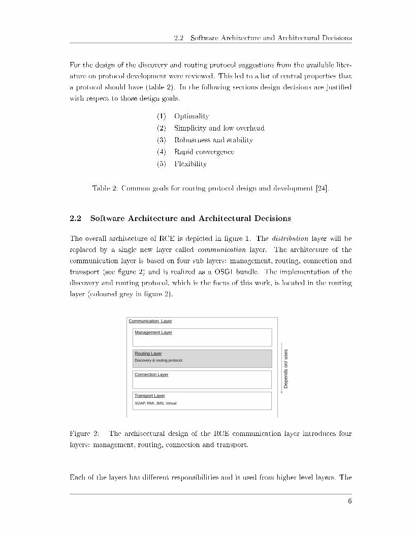
2.2 Software Architecture and Architectural Decisions
The overall architecture of RCE is depicted in �gure 1. The distribution layer will be
replaced by a single new layer called communication layer. The architecture of the
communication layer is based on four sub layers: management, routing, connection and
transport (see �gure 2) and is realized as a OSGI bundle. The implementation of the
discovery and routing protocol, which is the focus of this work, is located in the routing
layer (coloured grey in �gure 2).
Communication Layer
Management Layer
Routing Layer
Connection Layer
Transport Layer
Dep
ends
on/
use
s
SOAP, RMI, JMS, Virtual
Discovery & routing protocol.
Figure 2: The architectural design of the RCE communication layer introduces four
layers: management, routing, connection and transport.
Each of the layers has di�erent responsibilities and is used from higher level layers. The
6

2.3 Supported Transport Methods
transport layer abstracts the concrete communication (e.g. SOAP, RMI, JMS, virtual)
in order to provide a common API for the connection service. Based on that, the connec-
tion layer provides functionality to establish direct connections to remote nodes without
making assumptions about the underlying transport protocol. On top of that the routing
layer uses these direct connections to discover nodes in the networks and to allow commu-
nication between nodes that are, potentially, not directly connected to each other. The
management layer serves as a container to provide functionally for live cycle management
of an instance (e.g. start up, shut down) and to register for network based events (e.g.
new instance discovered).
In order to allow di�erent implementations of the layers as well as injection of "mock"
implementations for tests, the inversion of control (IoC) pattern is applied. Using IoC
every layer publishes its dependencies that are then resolved by the context in which the
communication layer is operated. This greatly facilitates testing of each layer in isolation
(details in section 4).
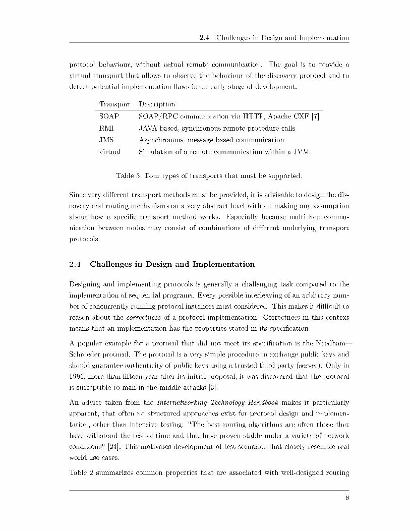
2.3 Supported Transport Methods
One central requirement for the design of the discovery and routing protocol is that
it must be general enough to support di�erent transport methods. Currently RCE is
supporting remote procedure calls via RMI and SOAP based communication. These
methods are used for di�erent kinds of communication such as exchanging messages
and noti�cations as well as bulk data transmission. Most communications are done
synchronously on the coding level, but the noti�cation layer also allows to register for
events in a publish/subscribe style.
In most practical use cases RCE is operated as a homogeneous network of RCE instances.
In such cases both RMI and SOAP are not the most e�cient ways of communication.
When using RMI remote procedure calls are done synchronously. If the remote instance
is not available in that moment, the call fails. The same is true for SOAP based point to
point communication without any intermediate infrastructure like an enterprise service
bus (ESB). In order to counter these issues the transport methods are planned to be
extended by Java Messaging Service (JMS) based communication. This will allow com-
municating fast and e�ciently in a homogeneous RCE network. JMS does not bear the
overhead associated with web service based communication. At the same time it loosens
the coupling between instances by providing a message querying system. Receivers of
messages must not be available in the very moment when the message is being send, but
can fetch the message from the query at a later point in time.
Finally a "virtual" transport method must be supported to simulate and test the discovery
7
2.4 Challenges in Design and Implementation
protocol behaviour, without actual remote communication. The goal is to provide a
virtual transport that allows to observe the behaviour of the discovery protocol and to
detect potential implementation �aws in an early stage of development.
Transport Description
SOAP SOAP/RPC communication via HTTP, Apache CXF [7]
RMI JAVA based, synchronous remote procedure calls
JMS Asynchronous, message based communication
virtual Simulation of a remote communication within a JVM
Table 3: Four types of transports that must be supported.
Since very di�erent transport methods must be provided, it is advisable to design the dis-
covery and routing mechanisms on a very abstract level without making any assumption
about how a speci�c transport method works. Especially because multi hop commu-
nication between nodes may consist of combinations of di�erent underlying transport
protocols.
2.4 Challenges in Design and Implementation
Designing and implementing protocols is generally a challenging task compared to the
implementation of sequential programs. Every possible interleaving of an arbitrary num-
ber of concurrently running protocol instances must considered. This makes it di�cult to
reason about the correctness of a protocol implementation. Correctness in this context
means that an implementation has the properties stated in its speci�cation.
A popular example for a protocol that did not meet its speci�cation is the Needham�
Schroeder protocol. The protocol is a very simple procedure to exchange public keys and
should guarantee authenticity of public keys using a trusted third party (server). Only in
1996, more than �fteen year after its initial proposal, it was discovered that the protocol
is susceptible to man-in-the-middle attacks [3].
An advice taken from the Internetworking Technology Handbook makes it particularly
apparent, that often no structured approaches exist for protocol design and implemen-
tation, other than intensive testing: "The best routing algorithms are often those that
have withstood the test of time and that have proven stable under a variety of network
conditions" [24]. This motivates development of test scenarios that closely resemble real
world use cases.
Table 2 summarizes common properties that are associated with well-designed routing
8
2.5 Link State Versus Distance Vector Protocols
protocols. Some of these properties may challenge each other such as low overhead
and rapid convergence (de�nition 2). A discovery procedure that is focused on rapid
convergence might send many messages across the network causing substantial overhead.
Inconsistent, incomplete or incorrect knowledge about the network state (i.e. topology)
cannot be avoided and must be handled within applications. This enforces an asyn-
chronous and defensive programming style that is relying on callbacks and timeouts
increasing the complexity of client/application code. Also error handling, forwarding
and interpretation are di�cult due to the fact that everything in a distributed system
can potentially fail at any time.
2.5 Link State Versus Distance Vector Protocols
Routing protocols can be grouped into two general categories: 'link state' and 'distance
vector' protocols [24]. Nodes in distance vector protocols forward routed messages based
on a distance metric. A message is forwarded to the node that is expected to be the
next hop (stopover) on the shortest path to the �nal receiver. When using a distance
vector protocol a node is only aware of its direct neighbours and a distance metric to any
destination node. Distance and direction can be interpreted as a vector hence the name
distance vector. Opposed to that, nodes in a link state protocol send information about
their direct neighbours (i.e. their link state) across the entire network. Nodes that receive
updated information about the link state of other nodes usually forward the update to
their neighbours (i.e. �ooding). This eventually allows every node to reconstruct the
topology of the network (a topology map). Routing a message is then reduced to �nding
the shortest path in a graph that represents the network.
2.6 Weighting Advantages and Disadvantages
Compared to link state protocols, distance vector protocols are generally simpler and
are consuming less computational resources (CPU time and memory). This simplicity
comes at a price though. Distance vector protocols do not scale to larger networks [20].
In fact the simple distance vector protocol Routing Information Protocol (RIP) [16]
limits the networks diameter to 15 nodes. Any two nodes with a greater distance cannot
communicate with each other. IGRP (Interior Gateway Routing Protocol) is another
distance vector protocol that extends the maximum network diameter (de�nition 1) to
as much as 255.
De�nition: 1. The maximum network diameter is the maximum distance to travel
(for instance measured in hop counts) [20].
9

2.6 Weighting Advantages and Disadvantages
Distance vector protocols are based on periodic updates (RIP: every 30 seconds, IGRP:
every 90 seconds). This generally limits speed of the convergence process (de�nition
2). Slow convergence behaviour in turn increases the likelihood of inconsistent topology
information in di�erent nodes. This makes distance vector protocols generally susceptible
to the count to in�nity problem where messages are forwarded in a loop (potentially
forever). A number of techniques have been implemented to counter routing loops (max
hop count, split horizon, etc.).
De�nition: 2. Convergence is achieved when all routes within a routing domain agree
on reachability information [20].
Link state protocols address some of the disadvantages of distance vector protocol at the
cost of higher resource consumption (CPU time, memory) and a more complex imple-
mentation. Increased complexity stems mainly from the fact, that link state protocols
do not rely purely on timed updates, but publish topology changes without delay. This
requires a node to trigger and interpret topology related events correctly. An example for
such an event would be a node that discovers a neighbour to be not available currently. It
must decide whether to retry later or to interpret the connection as 'broken' and publish
the change.
The increased CPU usage associated with link state protocols is mainly caused by the
computation of routes. Every node knows about all other nodes in the network and
their connections. From this information every node must compute a route to the �nal
receiver when sending a message. Using Dijkstra's algorithm to �nd the shortest path
this requires a running time of O(n · log(n)). The requirement to know the topology of
the entire network graph, only to compute the next hop, might eventually have limiting
in�uence to the scalability in large networks.
When designing a discovery and routing protocol for distributed computing the increased
resource consumption is an acceptable trade-o�, since routing nodes are typically servers
or at least strong desktop computers. The increased complexity of the protocol imple-
mentation can be handled with high level technologies such as JAVA or C++ in the
application layer of the TCP/IP stack. Obviously any speci�cation and implementation
must undergo extensive automated testing.
The fact that, when using link state protocols, every node maintains a topology map
of the entire network facilitates monitoring and debugging. The entire network with
all nodes and channels can easily be visualized allowing user interaction and selecting
routes preferred by the user. In addition, when a node computes a route, it can take into
account more dynamic and sophisticated route computations based on weighted edges
representing bandwidth, reliability or preferred transport methods (e.g. JMS over SOAP)
10

2.6 Weighting Advantages and Disadvantages
without changing the actual protocol implementation.
These considerations together with the central requirements collected in section 2.1 led
to the decision to design a node discovery protocol that is based on the ideas of link state
routing protocols.
11
3 Modelling and Implementation
The following sections show how a discovery procedure that is based on exchanges of
topology information can be realized. First some basic terminologies are introduced along
with their de�nitions. Based on those, a procedure for node discovery in static networks
is proposed that is as simple as possible. Then the procedure is step by step extended to
cope with dynamics in the network. The focus is to suggest a robust protocol that is as
simple as possible and to avoid premature optimizations. Finally potential optimizations
are outlined and the actual routing of messages is brie�y discussed.
3.1 Basics and De�nitions
As a foundation for a discovery mechanism, nodes must be identi�able. Therefore the
concept of a Universally Unique Identi�er (UUID) was introduced. In general a UUID
allows identifying resources unambiguously in a distributed system. Nodes generate an
ID once and are from then on identi�able via this ID. The ID must be persistent across
application restarts. When the ID is reset the node is treated as a new and di�erent node.
This concept allows addressing nodes logically. A central goal of this work is to enable
nodes to communicate with each other using a logical addressing. Logical addresses are
translated into network routes by the routing layer. The ID be used not only in the
communication layer but may be used in other parts of the software for instance for
identi�cation in distributed work�ows or for references in experimental data.
In addition to logical addresses nodes must provide physical address for communication.
These physical addresses are referred to as a network contact points (NCP). They are
composed of a host address (i.e. IP address), a port number and a transport protocol
(e.g. SOAP, RMI, JMS).
De�nition: 3. A network contact point (NCP) can be provided by a node to enable
establishment of connections. It consists of a host identi�er (IP address), a port identi�er
and a transport protocol. It is not globally unique, but sensitive to the context it is used
in.
As currently implemented in the RCE framework, a node sends messages to another node
by connecting to one of its NCP. Thus, to receive a message, a node is required to provide
at least one NCP. In terms of a SOAP communication, for instance, this means that every
node must provide a SOAP server to receive messages. The set of NCPs that is provided
by a node may dynamically change and the same node might be visible (addressable) via
di�erent NCPs depending on the location of the connecting node. It is important to note,
12

3.2 Link State Advertisements
that NCPs are not globally unique as, for instance, the NCP (192.168.0.1, 4711, SOAP )
may resolve to di�erent nodes in di�erent local area networks. A connection from a node
to a network contact point will be referred to as link (def. 4), because this notation �ts
best in the terminology of routing protocols.
De�nition: 4. A link is a connection from a node, identi�ed by its ID, to a network
contact point (NCP). A node can potentially establish and maintain multiple links to
the same NCP.
Figure 3 exempli�es how nodes and network contact points can relate to each other. In
the following sections images of network topologies will not include NCPs to provide a
better overview.
Fig. ?:
Node that is identifiable by a UUID.
b)N1
1N2
2
i A network contact point (NCP)
N11
N2
2
N3
4
3
Link
a)
N1N2 N31 N1 N2
1c) d)
Figure 3: Example scenarios for network contact points.
Connections (i.e. links) are always established towards a NCP. To identify the node
that is contactable using a NCP, the remote node must send its ID as a response after a
connection was established. Only then the connecting node can be sure of the identity of
its communication partner. Storing and managing relations between NCP and node IDs
is achieved with the help of a topology map. Details of the topology map are discussed
below. A link does not necessarily represent an open TCP connection. It represents more
abstractly the observation that a communication attempt has succeeded at least once.
3.2 Link State Advertisements
Based on the concept of UUIDs for node identi�cation and NCPs for physical addressing,
every instance must be equipped with a list of one or more initial NCPs. This list serves
as an entry point to an existing network. A node can connect to these NCPs and request
13

3.2 Link State Advertisements
information about the remote node including its UUID. The list of initial NCPs is a
priori knowledge and must be con�gured manually. It can be extended at runtime to
allow users to add RCE instance for direct connection. Based on the NCPs that are
known to a node it can build up a list of its neighbouring nodes (def. 5) by trying to
connect to each NCP and retrieving the remote node ID. This process is also referred to
as neighbour sensing.
De�nition: 5. The neighbourhood (or adjacency) of a node is de�ned as the set of
nodes, that are directly addressable using all NCPs that are known to the node. Only
nodes that could successfully be connected to are included in the neighbourhood.
At the time when a node builds up a list of neighbouring nodes, some of these nodes
may not be reachable and are therefore not part of the neighbourhood. All currently
established connections to NCPs (e.g. links) together with the neighbourhood of a node
makes up the link state of a node. Potential connections to a node are not part of the
link state.
De�nition: 6. The link state of a node are the currently established connections to
known NCPs (i.e. links) together with the set of nodes that are reachable using the
known NCPs (i.e. the neighbourhood).
The current link state of a node summarizes its connection to other nodes. It can be
interpreted as a tree shaped graph with a central node as the root and directed edges
to the leafs. The fundamental principle of link state routing protocols is that nodes
advertise their link state to other nodes. In order to achieve this, a network message can
be created from the link state of a node. The message contains all information about
the link state of the node, as well as some meta information in order to allow di�erent
interpretations. Such a network message will be referred to as link state advertisement
(LSA) and are sometimes also known as topology control messages (TC messages).
De�nition: 7. A link state advertisement (LSA) or topology control message is a net-
work message, that contains all information about the link state of a node and additional
meta data (e.g sequence number).
When a node is producing a LSA message from its current link state it also increments
a sequence number. The sequence number is then attached to the LSA message. When
another node receives the LSA it can decide whether it is the �rst time that it received
this particular LSA message.
14
3.3 The Network Topology Map
3.3 The Network Topology Map
The principle of link state protocols is that each node develops a view of the network
that is called topology map (or link state database). The topology map is built and
adopted over time from received links state advertisements. It is essentially a directed
graph that contains all links (edges) and nodes (vertices) that are currently present in
the network. Because more than one link can exist between two nodes the topology map
must be a multigraph. Edges are directed from the node that established the connection
to the remote node. Although it is desirable that the topology map eventually models
the current network state, it is not required to do so at any point in time. Also a node
does not have any notion of its topology map being in sync with the current state of the
system.
The following sections describe the discovery process that allows building up the topology
map. Once a map is built it serves as foundation of the actual routing algorithm. Finding
a route can be reduced to the computation of a shortest path on a weighted graph which
is a solved problem. Details on the routing procedure are described in section 3.7.
For the implementation of the topology map the Java framework JUNG (Java Universal
Network/Graph Framework) [25] was used. It provides a mature library of network
and graph data structures as well as algorithms that work on the data structures. It is
particularly handy, that the framework provides shortest path computation like Dijkstra's
algorithm out of the box.
3.4 The Discovery Process in Static Scenarios
As described in [14] the simplest way to implement a decentralized node (i.e. peer)
discovery procedure is using network �ooding. In this case every node broadcasts its
knowledge about the network to its neighbourhood. Nodes may forward the received
information to their neighbours whereby the knowledge eventually propagates across the
whole network. In the �rst design stage of a discovery procedure, a number of simplifying
assumptions are made. First, the network must be static, which means that the number of
nodes is �xed and that the links between nodes is determined in advance. Second, nodes
are always started and do not change their state, which means that they cannot shut
down, restart or crash. Finally, from every node there must be a path to any other node.
This condition can easily be satis�ed when two nodes are always connected bidirectionally.
These assumptions allow to develop a simple decentralized discovery procedure based on
sending and forwarding LSAs as shown in listing 1. The procedure is described from the
view of a single node. Every node is required to execute this procedure.
15
3.4 The Discovery Process in Static Scenarios
1 produce one LSA message and broadcast i t to a l l ne ighbours ;
2 AFTER r e c e i v i n g any LSA DO
3 IF LSA conta in s new in format ion THEN
4 update topology map AND broadcast r e c e i v ed LSA;
Listing 1: An outline of a fundamental discovery protocol.
As mentioned above, scenarios where some nodes are still preoccupied in the start-up
or initialization phase while others are already started up and ready to send LSAs are
excluded at this stage. It is still interesting to investigate the convergence behaviour in
such a simpli�ed scenario. On the one hand it resembles the optimal case, where sending
only one single LSA per node always leads to convergence. On the other hand it serves as
a reference point for future optimizations in the �ooding process that may try to reduce
the total number of send LSA messages.
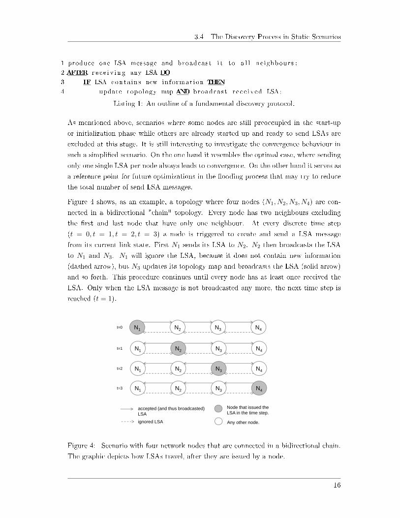
Figure 4 shows, as an example, a topology where four nodes (N1, N2, N3, N4) are con-
nected in a bidirectional "chain" topology. Every node has two neighbours excluding
the �rst and last node that have only one neighbour. At every discrete time step
(t = 0, t = 1, t = 2, t = 3) a node is triggered to create and send a LSA message
from its current link state. First N1 sends its LSA to N2. N2 then broadcasts the LSA
to N1 and N3. N1 will ignore the LSA, because it does not contain new information
(dashed arrow), but N3 updates its topology map and broadcasts the LSA (solid arrow)
and so forth. This procedure continues until every node has at least once received the
LSA. Only when the LSA message is not broadcasted any more, the next time step is
reached (t = 1).
Fig. ?: C=Client, S=Server
N2N1 N3 N4
accepted (and thus broadcasted)LSA
ignored LSA
Node that issued theLSA in the time step.
Any other node.
N2N1 N3 N4
N2N1 N3 N4
N2N1 N3 N4
N1, Nn: send: n, received: n, rejected: 1, max hop count: n-1 N2, ..., Nn-1: send: 2n, received: 2n, rejected: n+1, max hop count: (n/2) + (|i-n|) -1
t=0
t=1
t=2
t=3
Figure 4: Scenario with four network nodes that are connected in a bidirectional chain.
The graphic depicts how LSAs travel, after they are issued by a node.
16

3.4 The Discovery Process in Static Scenarios
In order to characterize the �ooding process some simple metrics are very informative.
First, it is interesting to measure how many LSAs a node has sent in total. The number of
sent LSAs summarizes all LSAs that have been sent by a node in order to advertise its own
link state, as well as those LSAs that have been received and broadcasted. Broadcasting
a single LSA to n direct neighbours increases the number of sent LSA by n (not by 1).
Next, the total number of received LSAs is helpful. It can be further split into LSAs that
contained new topology information and are therefore forwarded (accepted) and LSAs,
that do not contain new information and are therefore not forwarded (ignored). The
following equation holds true received = accepted + ignored. Finally messages, as they
travel through the network, pass a number of nodes which is referred to as the hop count.
Based on the procedure from listing 1 the highest hop count that a node can observe
can be determined (max hop count). The maximum observed hop count of any node
cannot be larger than the number of nodes. A more restrictive upper bound for the
max hop count is the diameter of the network. Such metrics give a �rst insight into the
�ooding process and allow comparing �ooding behaviour in di�erent topologies. Table 4
summarizes the four metrics.
Metric Interpretation
sent Number of sent LSAs (own LSAs and forwarded LSAs).
Forwarding/broadcasting to n nodes increases sent by n.
received Number of received LSAs (received = accepted + ignored)
ignored LSAs that do not contain new information
accepted LSAs that contain new information and are broadcasted
max hop count The highest hop count of a LSA message that a node can observe
Table 4: Metrics to describe the �ooding process. The numbers re�ect observations ofsingle nodes.
In case of a chain topology, as in �gure 4, after n time steps every node has sent (either
generated or forwarded) 2n LSAs, received 2n LSAs and ignored n−1 LSAs. Exceptions
are the �rst and last node, that send and receive only half as many LSAs (namely n) and
ignore only one LSA. The max hop count observed by the �rst and last node is n − 1
and for any other node it equals to the distance of the node that is farthest away (i.e.
min(n− i, i)− 1).
Along with chain topologies other characteristic topologies can be investigated. Figure 5
compares the discussed chain topology (a) to a bidirectional ring or token topology (b),
a bidirectional star or client/server topology (c) and a directed ring topology (d). Note
that topologies are deliberately chosen so that from any node there exists a path to every
17
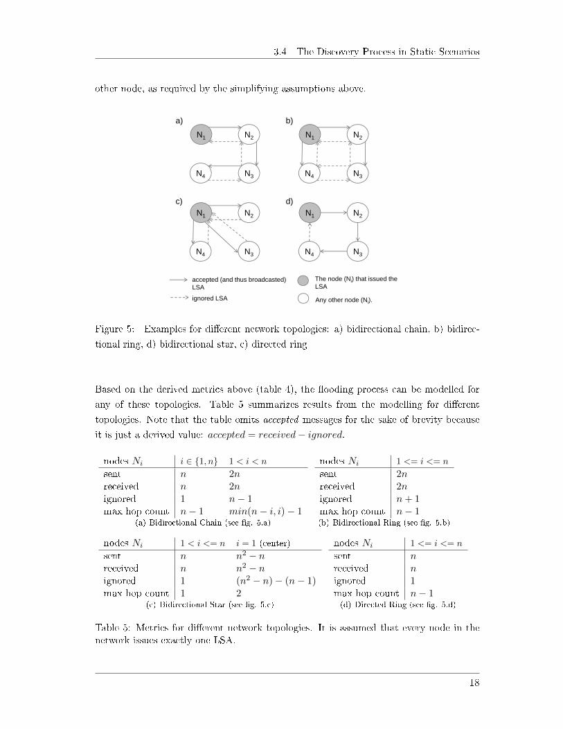
3.4 The Discovery Process in Static Scenarios
other node, as required by the simplifying assumptions above.
Fig. ?:
N2N1
N3N4
The node (Ni) that issued theLSA
Any other node (Ni).
N2N1
N3N4
N2N1
N3N4
N2N1
N3N4
a) b)
c) d)
accepted (and thus broadcasted)LSA
ignored LSA
Figure 5: Examples for di�erent network topologies: a) bidirectional chain, b) bidirec-
tional ring, d) bidirectional star, c) directed ring
Based on the derived metrics above (table 4), the �ooding process can be modelled for
any of these topologies. Table 5 summarizes results from the modelling for di�erent
topologies. Note that the table omits accepted messages for the sake of brevity because
it is just a derived value: accepted = received− ignored.
nodes Ni i ∈ {1, n} 1 < i < n
sent n 2nreceived n 2nignored 1 n− 1max hop count n− 1 min(n− i, i)− 1
(a) Bidirectional Chain (see �g. 5.a)
nodes Ni 1 <= i <= n
sent 2nreceived 2nignored n + 1max hop count n− 1(b) Bidirectional Ring (see �g. 5.b)
nodes Ni 1 < i <= n i = 1 (center)
sent n n2 − nreceived n n2 − nignored 1 (n2 − n)− (n− 1)max hop count 1 2
(c) Bidirectional Star (see �g. 5.c)
nodes Ni 1 <= i <= n
sent nreceived nignored 1max hop count n− 1(d) Directed Ring (see �g. 5.d)
Table 5: Metrics for di�erent network topologies. It is assumed that every node in thenetwork issues exactly one LSA.
18

3.5 Node Discovery in a Dynamic Network
The results indicate that the number of sent messages per node linearly scales with the
network size in realistic network topologies. A realistic network topology in this context is
a graph that has substantially less edges than a fully mashed network. When the network
graph would become fully mashed the number of sent messages per node is Θ(n2).
When considering realistic topologies, the tra�c volume increases quadratic as a function
of network size (node count) from a global network perspective. On the one hand mod-
elling the most basic discovery algorithm like this gives a lower limit for the e�ciency of
the process. Any procedure that requires more than n2 messages to reach convergence
is undesirable. On the other hand it is obvious, that the procedure must be further
optimized to scale to larger networks.
Another noteworthy observation is the message volume in the bidirectional star topology.
This topology resembles a client/server architecture. Client/serve topologies are not
uncommon based on practical experience from current RCE deployments. A server might
coordinate a distributed computing work�ow or may itself provide computational services.
In such cases the central node might become a bottle neck, because the central node must
forward messages in the order of Θ(n2) (table 5(c)). Section 3.6 will discuss optimizations
that address these kinds of shortcomings.
An additional bene�t of the derived �ooding metrics and their modelled dimensions in
di�erent topologies is that they facilitate to formulate test cases. Equipped with predicted
values for the metrics, a network topology can be simulated and tested against observed
values. Being able to formulate such expectations is the foundation for automated tests
that can be executed after a simulation. Section 4 describes the developed methods for
automated testing in greater detail.
3.5 Node Discovery in a Dynamic Network
Based on some simplifying assumptions the section above describes how nodes in a net-
work can be noti�ed about each other's presence in a network, when the network is static.
This discovery algorithm meets three of the �ve desired design goals that were identi�ed
in the introduction (table 2). It is simple and produces little overhead, it is robust and
stable (under the given simpli�cations) and it converges rapidly. It is however neither
optimal nor �exible. The latter is subject to this section. The ambition is to maintain
simplicity, robustness and rapid convergence while introducing �exibility.
The �exibility goal requires the discovery process to be able to adopt to dynamics in
the network. Reasons for dynamic changes in a distributed computing environment are
manifold. Nodes may join or leave the network on a regular basis. Nodes may also go
19

3.5 Node Discovery in a Dynamic Network
o�ine and later reconnect from a di�erent location in the network. Another source for
changes are failures of network components, that can have again a variety of causes.
Nodes might get temporary unavailable or connections might fail or become unstable.
In short, everything can fail any time. Accounting for such dynamic changes brings the
discovery algorithm closer to real world applications.
Section 2.5 highlighted the di�erences between link state and distance vector routing pro-
tocols. One major di�erence is how changes are propagated across the network. Distance
vector protocols exchange information periodically. Whenever changes occur the next
update will communicate these changes. The static discovery protocol from the above
section can be extended by such a mechanism easily. Based on a �xed time period the
protocol in listing 1 could simply be repeated. Proceeding like this, inherently limits the
speed of the convergence process and restricts scalability as Θ(n2) messages are sent on
each update. Link state protocols, on the other hand, rely on an event based propagation
of topology information. Whenever a node observes a change in its link state, this change
is broadcasted immediately. While this speeds up convergence, events must be carefully
interpreted and translated into network messages. Next to reaching quick convergence
it becomes necessary to show that convergence is always eventually reached by a given
protocol. It must be excluded that any arbitrary sequence of events may cause a topology
change to be not properly communicated.
The static �ooding procedure from the above section can be reused as a general foundation
for a more dynamic discovery. It speci�es that received LSAs are forwarded if they are
new to the node and are otherwise ignored. The following listing is identical to listing 1
excluding the �rst line. It will be extended in the following paragraphs.
1 AFTER r e c e i v i n g any LSA DO
2 IF LSA conta in s new in format ion THEN
3 update topology map AND broadcast r e c e i v ed LSA;
Listing 2: The basic LSA �ooding algorithm.
The simplest and most frequently occurring reason for network dynamics are joining and
leaving nodes. They must properly advertise their state after joining and before leaving.
The semantics of joining and leaving nodes are re�ected in annotated LSA messages that
are referred to as init- and shutdown-LSA respectively. Listing 3 shows how these events
trigger message sending.
1 AFTER s t a r t i n g up DO send i n i t−LSA;
2 BEFORE shut t ing down DO send shutdown−LSA;
Listing 3: Protocol extension for joining and leaving nodes.
20

3.5 Node Discovery in a Dynamic Network
Sending init- and shutdown-LSAs is su�cient to let every node in the existing network
know about leaving and joining nodes but the joining nodes themselves do not receive
any information about the network. One approach to account for this would be to let
every node issue a LSA to advertise their own state whenever they receive a init-LSA.
This would be su�cient to converge the network but does cause considerable tra�c when
nodes join (Θ(n2) per node). A more optimal procedure is, to let a joining node be
updated only by its direct neighbour(s). In the OSPF speci�cation this is also referred
to as the "database exchange process" emphasizing that the topology knowledge of two
nodes is synchronized. Neighbours respond to a init-LSA by sending a list of LSAs
that represents the entire topology (i.e. one LSA for every node). A list of LSAs that
represents the entire view of a node on the network is referred to as batch-LSA. Listing 4
extends the protocol with such behaviour. At this stage nodes that receive a batch-LSA
do never forward it.
1 AFTER r e c e i v i n g i n i t−LSA DO2 IF sender i s d i r e c t neighbour THEN send batch−LSA as a response ;
3 AFTER r e c e i v i n g batch−LSA DO update topology map ;
Listing 4: Protocol extension to update joining nodes.
Interpreting a shutdown-LSA message is as simple as removing the node and links to and
from that node from the topology map (listing 5).
1 AFTER r e c e i v i n g shutdown−LSA DO2 remove node and l i n k s from topology map .
Listing 5: Protocol extension for leaving nodes.
The concept of init-, shutdown- and batch-LSAs allows single isolated nodes to join and
leave the network while ensuring that a quick convergence is reached with a low number
of messages.
So far the protocol assumes that a network only grows and contracts by single nodes
but a common use case is also merging of existing networks. In such a case new links
are established between nodes that are already running. These changes in the own link
state of a node must also trigger LSA messages. The situation is similar to the scenario
of single joining nodes where one joining node must receive the information about the
entire topology because it knows nothing about the network. When networks merge then
both sides of the new link must receive a batch-LSA from its remote counterpart. This is
achieved with line 2 in the following listing. Sending a init-LSA triggers the remote node
to send a batch-LSA response (see listing 4). When the link state changes such, that
links are removed, the new link state is simply broadcasted using a update-LSA (listing
21

3.6 Optimized Node Discovery
6 line 1).
1 AFTER l i n k removed DO send update−LSA;
2 AFTER l i n k added DO send i n i t−LSA AND send batch−LSA via new l i n k ;
Listing 6: Communicating changes in the link state.
Listing 6 shows how changes in the link state trigger message sending. Newly connecting
nodes are updating themselves via batch-LSA messages. In order to inform all other
nodes in the two merged networks about the nodes in the other network, batch-LSAs
must be forwarded so that they travel through the whole network. Every node that
receives a batch-LSA must �lter this LSA list to exclude already known link states (by
comparing sequence numbers) before forwarding it. This enables merging networks to
quickly discover participants in the newly connected network.
1 AFTER r e c e i v i n g batch−LSA DO forward f i l t e r e d batch−LSA;
Listing 7: Forwarding the �ltered batch-LSA.
Table 6 summarizes the four di�erent types of LSA message that are used in the discovery
process.
Message Type Meaning
init-LSA Node broadcasts initial link state to new links
triggering a batch-LSA in response.
update-LSA Node broadcasts current link state.
shutdown-LSA Node broadcasts intend to shut down/leave the network.
batch-LSA A list of LSAs, that represents the topology map of the sending node.
Table 6: Di�erent types of LSA messages.
3.6 Optimized Node Discovery
Section 3.4 described the fundamentals of a �ooding process without taking any topology
changing events into account. Each node simply sends one LSA. This most basic pro-
cedure leads to a converged network. Section 3.5 extends this procedure with a number
of events that trigger the nodes to send LSA updates in order to respond to topology
changes. This allows handling more realistic scenarios where nodes join and leave the
network frequently. How such a basic discovery protocol performs in real world scenarios
remains to be investigated. The discovery procedure can be used as a starting point for
22

3.7 Message Routing
optimization. Proposed optimizations can be benchmarked against this implementation
in order to evaluate the bene�ts.
At this stage it is di�cult to speculate about potential optimization because they may
heavily depend on the domain of application. For instances a routing mechanism might
be optimized to �nd routes that are as short as possible in terms of hop counts. Such
a protocol applied in wireless Mobile At-hoc NETworks (MANET) will favour routes
where intermediate nodes have high geographical distance in order to reduce hop count.
In consequence routes that are less reliable are selected over routes that are more reliable
but require more intermediate nodes. Another example is the Optimized Link State
Routing Protocol OLSR [1] that introduces improvements for link state based routing
protocols that are applied in MANETs. The authors of [12] argue that the Multi Point
Relay (MPR) optimization, that makes the �ooding process more e�cient, is in fact
unsuitable in practical applications for MANETs.
Such examples empathize that optimization must be applied with caution and should be
evaluated in practice. A starting point for optimization is to generally reduce the number
of messages that have to be exchanged. One step in this direction, as also suggested by
the authors of [20], is to not �ood messages backwards to the origin. This optimization
is currently not considered in the protocol above. Such directed �ooding appears to be
particularly bene�cial in star-like topologies as it relieves the central node. Another ap-
proach to reduce the number of messages sent is to aggregate messages before forwarding.
The OLSR is using this technique to reduce the messages numbers. Furthermore the pro-
tocol might be extended by time based periodic updates complementing the event based
link state updates. When such a timer is introduces it is advisable to use a random jitter
in order to avoid unwanted synchronisation over time as done by OSPF.
Another category of improvements is the optimization of the code base. Refactoring the
code base with respect to optimized data structures and introducing caches instead of
re-computing information from the topology map might o�er potential for improvement.
3.7 Message Routing
Through �ooding link state advertisements across the network, every node is able to build
a topology map of the network. This topology map is the input for the routing algorithm.
In most cases this is a shortest path algorithm that can account for (positively) weighted
edges such as Dijkstra's algorithm (the OSPF protocol for instances uses Dijkstra's algo-
rithm). Table 8 outlines a high level view on the routing process. An important fact is
that the distributed algorithm requires each node on a route to re-compute the shortest
path from its perspective only to �nd the most optimal subsequent node.
23

3.8 Optimized Routing
1
2 AFTER r e c e i v i n g a message DO BEGIN
3 IF cur rent node i s r e c e i v e r THEN proce s s message ELSE
4 BEGIN
5 compute s h o r t e s t path to r e c e i v e r ;
6 IF path can be found THEN forward message ELSE f a i l ;
7 END
8 END
Listing 8: The routing procedure.
Routing protocols can be classi�ed using the categories listed in table 7. The described
protocol would classify as dynamic, due to the fact that nodes can join and leave the
network while the protocol is operating. Because messages are not routed across possible
alternatives, but only along the shortest path, the implementation corresponds to single-
path routing. The network is composed of homogeneous RCE instances that do not allow
to introduce any hierarchies, thus the topology is �at. Since every router must maintain
a topology map and must reason on the best path to a destination node, it the protocol
is best described as router-intelligent. The network of RCE instances is interpreted as
a single network forming only one domain without any logical sub networks, therefore
the protocol is an intra-domain protocol. Finally for reasons described in section 2.5 the
protocol categorizes as link-state.
(1) static vs. dynamic
(2) single-path vs. multipath
(3) �at vs. hierarchical
(4) host-intelligent vs. router-intelligent
(5) intra-domain vs. inter-domain
(6) link-state vs. distance-vector
Table 7: Six di�erent criteria to describe routing protocols [24]. Categories that apply
to the developed routing protocol are marked in bold.
3.8 Optimized Routing
As with the suggested optimizations for the discovery process in section 3.6, optimizing
the routing process must be done in close interplay with practical evaluation. The design
goals in table 2 can be used as a general guidepost for improvements. In the near future
24

3.8 Optimized Routing
it will be interesting to add weighting to the routing algorithm. Generally this should
not be a problem, because the used algorithm is able to account for weighted edges in the
topology graph. As done in OSPF, it is advisable to derive a single dimensionless metric
for link weights that can be communicated within link state advertisements. Every node
calculates weights for its links state to favour, for instances, fast JMS connections over
relatively slow SOAP communication.
The current implementation is aimed to be as simple as possible. Routes through the
graph are directly computed from the topology map without building up a routing ta-
ble. While this is su�cient for a prototypical implementation, it o�ers potentials for
improvement to introduce a routing table as a cache for computed routes.
Reaching robustness is at this point certainly an open task. A concept for handling
failures during message routing must cover a variety of failure scenarios. Every component
whether hardware or software can potentially fail in any moment.
25

4 Simulation and Test
Section 2.4 already highlighted that speci�cation, design and implementation of commu-
nication protocols is in general challenging. This motivated to focus on the development
of testing and simulation methods within the scope of this project. Automated testing
has gained wide adoption in the software engineering community. Writing test cases next
to the actual implementation or even before (e.g. Test Driven Development) can result in
a signi�cant increase of quality. Today mature frameworks (e.g. JUnit [5]) are available,
that facilitate to write and execute automated tests. Despite its name JUnit is suited not
only for unit test execution but also for automation of any kind of tests. In this project
JUnit was used as a framework to author and execute automated tests and proved to be
a good choice.
4.1 Unit Testing
Tests can be characterized by the degree of isolation they require for their execution. At
the lower end of the scale are unit tests that examine small parts of complex systems
in isolation. Unit tests allow increasing the con�dence in the correctness of a system
by assuring that the decomposed parts of a system behave as expected. With the help
of unit tests, re�nements of APIs can be done at an early stage of development making
them more stable in later stages. Furthermore changes and optimizations of the data
structures can be done with more con�dence since regression issues can be discovered
quickly.
Designing for unit testing requires a system to be decomposable. A central aspect of
modularity and decomposability is the management of dependencies. Tightly coupled
and highly dependent modules that make assumptions about implementation details are
di�cult to isolate and hinder decomposition. To counter this problem control about
dependencies is moved out of the components and is left to a central component or the
executing context. This architectural pattern is often referred to as Inversion of Control
(IoC) and promotes loose coupling. When executing isolated system components in a
test context, dependencies can be resolved by "mock" implementations. This focuses the
execution onto the unit under test.
Architectural decisions in the RCE network layer (�gure 2) were guided by these principles
leading to a layered architecture where layers are relatively loose coupled. Basic classes
and data structures such as the topology map (section 3.3) or the link state advertisement
(section 3.2) were implemented directly next to their unit tests. This facilitated designing
APIs that were suitable in later stages of development. Many potential design �aws could
26
4.2 Virtual Transport and Virtual Instances
be discovered and �xed early with the help of a test driven approach.
The data structure that was used to represent the topology map encapsulates a data
structure that is provided by the Java Universal Network/Graph Framework (JUNG [25]).
It is essentially a directed sparse multigraph to which analysis algorithms like shortest
path computation can be applied. Test driven development made unexpected behaviour
and side e�ects observable during implementation (e.g. removing a vertex from a graph
also removes incident edges).
4.2 Virtual Transport and Virtual Instances
Appropriate unit testing with reasonable code coverage (lines of code that are covered
by tests) serves as solid foundation for the implementation of a discovery and routing
protocol. But unit tests are not suitable to test the message exchanging in a protocol
because components are only tested in isolation. To investigate interaction and message
exchange between multiple participants in a protocol, higher level tests are required. For
instance it is interesting to test, if a LSA message eventually propagates across the entire
network. Such a test might then be executed on di�erent network topologies that might
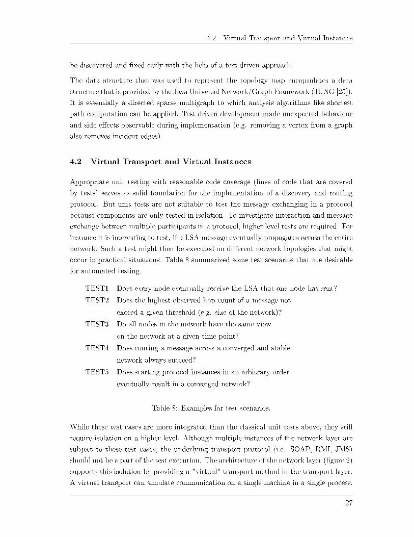
occur in practical situations. Table 8 summarized some test scenarios that are desirable
for automated testing.
TEST1 Does every node eventually receive the LSA that one node has sent?
TEST2 Does the highest observed hop count of a message not
exceed a given threshold (e.g. size of the network)?
TEST3 Do all nodes in the network have the same view
on the network at a given time point?
TEST4 Does routing a message across a converged and stable
network always succeed?
TEST5 Does starting protocol instances in an arbitrary order
eventually result in a converged network?
Table 8: Examples for test scenarios.
While these test cases are more integrated than the classical unit tests above, they still
require isolation on a higher level. Although multiple instances of the network layer are
subject to these test cases, the underlying transport protocol (i.e. SOAP, RMI, JMS)
should not be a part of the test execution. The architecture of the network layer (�gure 2)
supports this isolation by providing a "virtual" transport method in the transport layer.
A virtual transport can simulate communication on a single machine in a single process.
27

4.2 Virtual Transport and Virtual Instances
This technique allows testing and analysing the logical protocol �ow in isolation. Results
and observations from tests can deliver valuable hints on performance and scalability of
the discovery process. Also potential optimizations in later stages can be investigated
and measured without distortions through physical network connection.
The virtual transport simulates message passing by directly triggering events that process
incoming messages. Serialization and deserialization of the transmitted message payload
is included to resemble remote communication as close as possible.
Process
Fig. ?: State machine
Virtual Instance A
Communication Layer
Transport LayerVirtual
Virtual Instance B
Communication Layer
Transport LayerVirtual
[other layers omitted] [other layers omitted]
Thread Thread
Figure 6: Virtual instances, modelled by a state machine, simulate network nodes. The
virtual transport allows to simulate remote communication.
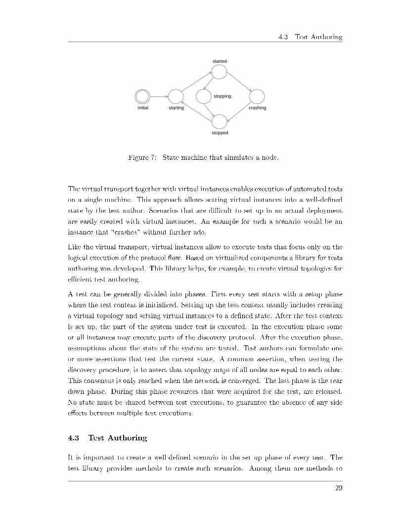
Complementary to a virtual transport, the concept of virtual instances has been intro-
duced. Virtual instances model real nodes (i.e. RCE instances) as state machines (see
�gure 7) and thereby serve as a host for the communication layer (�gure 6). The model
provides all aspects that are relevant for test execution, but omits details that are not
subject to the tests. The behaviour of an instance is entirely determined by its state
machine. The model in �gure 7 can be extended with additional states to simulate be-
haviour that might be interesting to investigate. In contrast to modelled instance, the
communication layer that is hosted within a virtual instance, executes the actual imple-
mentation. State changes in virtual instances are delegated to the communication layer
implementation, so that it can react to them. Using the actual implementation within a
modelled instance permits to test not only the speci�ed protocol behaviour, but also its
concrete implementation.
28
4.3 Test Authoring
Fig. ?: State machine
crashing
started
stopping
initial starting
stopped
Figure 7: State machine that simulates a node.
The virtual transport together with virtual instances enables execution of automated tests
on a single machine. This approach allows setting virtual instances into a well-de�ned
state by the test author. Scenarios that are di�cult to set up in an actual deployment
are easily created with virtual instances. An example for such a scenario would be an
instance that "crashes" without further ado.
Like the virtual transport, virtual instances allow to execute tests that focus only on the
logical execution of the protocol �ow. Based on virtualized components a library for tests
authoring was developed. This library helps, for example, to create virtual topologies for
e�cient test authoring.
A test can be generally divided into phases. First every test starts with a setup phase
where the test context is initialized. Setting up the test context usually includes creating
a virtual topology and setting virtual instances to a de�ned state. After the test context
is set up, the part of the system under test is executed. In the execution phase some
or all instances may execute parts of the discovery protocol. After the execution phase,
assumptions about the state of the system are tested. Test authors can formulate one
or more assertions that test the current state. A common assertion, when testing the
discovery procedure, is to assert that topology maps of all nodes are equal to each other.
This consensus is only reached when the network is converged. The last phase is the tear
down phase. During this phase resources that were acquired for the test, are released.
No state must be shared between test executions, to guarantee the absence of any side
e�ects between multiple test executions.
4.3 Test Authoring
It is important to create a well-de�ned scenario in the set up phase of every test. The
test library provides methods to create such scenarios. Among them are methods to
29
4.3 Test Authoring
create arbitrary numbers of virtual instances and to initialize these instances to a given
state. Also methods that create virtual topologies are provided. Examples of virtual
topologies include client/server topologies (or star topologies), ring topologies and chain
topologies. These fundamental topologies were taken from the modelling phase where the
�ooding procedure was modelled (section 3.4). With the aid of the modelled behaviour
of the �ooding process, test scenarios can be created and tested against their predicted
behaviour. For instances, the predicted maximum observed hop count or the number of
LSAs, that are sent by every node can be asserted in a test.
These assertions are possible through the concept of a virtual transport. The virtual
transport provider can easily observe the global network tra�c because every virtual
instance is represented by a thread in the same process. This is a major advantage of
virtual test execution over tests executed in an actual deployment. The global perspective
on the network allows implementing additional features for test authoring. One obvious
example is counting the number of messages that are sent across the network. Besides
such basic test scenarios, the test library also facilitates authoring more sophisticated
test logics. An example for such a test is to wait until no more messages are exchanged
anywhere in the network for a given period of time. Such a method can be used to
deliberately wait before making assertions on the current state of the network.
Virtualizing instances, transport and topologies helps to create parameterized test cases.
In order to make tests parameterizable they should not, if possible, use �xed numbers
for the network size (i.e. number of nodes) or absolute addressing of instances. An
example for a parameterized test case would be a test that creates a chain topology
with n nodes in its set up phase. Afterwards the test might start every instance in an
arbitrary order, wait until no more messages are exchanged in the network and then
assert that the �rst node can send a routed message to the last node in the chain (i.e.
relative addressing). Such test cases are then very �exible and reusable. An obvious
advantage is that the discovery procedure can be easily tested and analysed at di�erent
scales. A protocol that performs well with ten instances can be quickly evaluated in a
scenario with 200 instances. Another advantage of �exible basic topologies is that they
can be composed to more complex topologies. Two independent ring topologies might,
for example, be connected via a chain topology. Such compositions of simple topologies
to more complex, large topologies give a great freedom to the test author.
Next to parameterized tests randomization is useful when authoring tests. Concatenat-
ing basic topologies to more complex topologies might be done with randomization in
order to increase variability in the tested scenarios. Randomization of topology com-
position can be achieved by selecting nodes for concatenation randomly. While such a
randomized composition allows generating a large variety of test cases, it makes it also
30

4.4 Simulation and Test of Node Discovery
easy to guarantee certain properties of the network graph. For instance when connecting
two topologies where it is known that each node can communicate to every other node.
When these two topologies are connected, then this property is conserved in the resulting
topology.
Randomization of tests might potentially introduce nondeterminism to the test execution.
A test might only fail or succeed in some cases but not in others. To discover failures
with the help of randomized topologies is a part of the bene�t of these kinds of tests. It is
guarantees that test cases are not limited by the creativity of the test author and increases
the chance to cover unexpected scenarios. Therefore a nondeterministic test execution is
inherent to randomized tests. To encounter this issue the test library supports repeated
test execution. The setup phase is executed once. Then the two phases of test logic
execution and assertions are executed repeatedly over a number of iterations. After
executing all iterations, the tear down phase of the test is reached. Each execution is
called referred to as a epoch. An example for a scenario where epochs are useful is, when
two random nodes are selected and it must be asserted that they are able to communicate.
The following section discusses concrete test scenarios that make use of these methods.
4.4 Simulation and Test of Node Discovery
Equipped with virtualized transports and instances, high level test cases that cover parts
of the protocol can be formulated. Listing 9 shows a simple test case, where a number
of virtual instances are connected into a ring topology (see �gure 5.b) and then started.
Eventually it is asserted that every node has the same view (topology map) on the
network. This test only succeeds when all messages necessary for node discovery are
triggered after start-up of an instance. These kinds of test cases are very valuable when
investigating di�erent possible discovery procedures. Link state routing protocols are
based on immediate propagation of topology changes. A well designed protocol should
be as simple as possible, achieve network convergence quickly and should be optimal
in terms of the number of send messages (table 2). Automated tests serve as a direct
feedback as to which extends these objectives are achieved.
1 Connect nodes in to a r ing topology ;
2 PARALLEL ( Sta r t up a l l nodes ) ;
3 observe network and wait u n t i l no more messages are exchanged ;
4 IF every node has the same view o f the network THEN
5 succeed ELSE f a i l ;
Listing 9: Simple test case for a ring topology.
31

4.4 Simulation and Test of Node Discovery
A test case like the listing above is not a synchronous and sequential execution but
is - at least partially - executed in parallel (line 2). Therefore such a test case does
not necessarily fail or succeed deterministically although it is executed with the same
parameters. To achieve a deterministic test behaviour explicit global synchronization
must be introduced. Again the virtual transport provider can be extended to support such
synchronisation features, as it can observe the entire tra�c on the network. This allows
to implement methods that enable statements such as in listing 9 line 3. The statement
waits until no more messages are exchanged. After such an explicit synchronization it
can be deterministically tested for network convergence (i.e. listing 9 line 4).
Another interesting simulation is a continuously growing network. Starting with a single
node, new nodes are added iteratively. Every new node is connected to a random node
in the existing network. This produces a spanning tree topology. After each iteration it
is tested for convergence (listing 10).
1 WHILE (NOT reached max epochs ) BEGIN
2 connect new node to random ex i s t i n g node ;
3 s t a r t up the newly connected node ;
4 observe network and wait u n t i l no more messages are exchanged ;
5 IF NOT every node has the same view on the network THEN f a i l ;
6 END
Listing 10: Simple test case with randomly added nodes.
More advanced simulations can be formulated easily. Listing 11 initially creates a ring
topology. After that, the following epoch is repeated: shut down random node, test
for convergence, send a routed message, start up the random node again. In a ring
topology two nodes have two alternatives to communicate with each other. One way
is to communicate along a path that is directed clockwise and the alternative is to use
a path that is directed counter clockwise. This property of ring topologies makes it
possible do shut down a single node without disconnecting any two nodes. When a node
is shut down it should, based on the discovery procedure proposed in section 3, send a
shutdown-LSA that will �ood the network. When the information of the disappearing
node is correctly �ooded across the network, every remaining node should be aware that
one of the two communication path is not available any more. No node should attempt
to send messages towards the node that has shut down. This is tested by selecting a
random sender and receiver node and sending a message from sender and receiver. If
this does not fail, the node that has been shut down is started up again. It will advertise
itself after start up with an init-LSA. Now the �rst epoch is �nished. This procedure will
be repeated several times. Only when the procedure of starting and stopping instances
causes the right LSA messages to be �ooded across the network, this test will succeed in
32

4.5 Concluding Remarks
every iteration.
1 Connect nodes in to a r ing topology ;
2 PARALLEL ( Sta r t up a l l nodes ) ;
3 observe network and wait u n t i l no more messages are exchanged ;
4 WHILE (NOT reached max epochs ) BEGIN
5 shut down a random node ;
6 observe network and wait u n t i l no more messages are exchanged ;
7 IF NOT every node has the same view on the network THEN f a i l ;
8 send a routed message from a random sender to a random r e c e i v e r
9 IF NOT sending succeeds THEN f a i l ;
10 s t a r t up the random node again ;
11 END
Listing 11: More advanced shut down/start up scenario.
Test cases like the the one above (listing 11) are the most stable once, because they
make little assumptions on the underlying protocol speci�cation. Therefore adoptions
in the protocol speci�cation do not require to rewrite the test cases. Instead of testing
shutdown- and init-LSAs in isolation, this test case asserts that, when nodes leave and
join, the network always reaches a converged state. It is irrelevant to the test, how exactly
the discovery mechanism achieves this. Like unit tests, these high level tests should focus
on one particular aspect. Test scenarios that mix di�erent aspects make it harder to
attribute test failure to a concrete aspect of the software. They might also hide other
failing assertions, because the test execution is stopped at the �rst failing assertion.
4.5 Concluding Remarks
During the course of this project much e�ort has gone into the implementation of unit
tests and the design of test scenarios. When compared by lines of code, test cases made
up approximately two thirds of the developed code base. In addition to test scenarios,
a library for test execution was developed, in order to allow high level test authoring as
described above. Well constructed test scenarios turned out to be vital to the development
of the dynamic discovery protocol. Changes and re�nements of the protocol could be
quickly investigated in a verity of of well documented use cases. Many issues that have
not been apparent in the design phase could be addressed and �xed at an early stage
with the aid of test driven development. Intensive automated testing not only helped to
develop sound components but also revealed underspeci�cation of parts of the components
and the discovery protocol.
Without such a large battery of tests cases, development would be disproportionately
33
4.5 Concluding Remarks
more time consuming and error prone. One conclusion was, that test scenarios were
most useful when they described what properties a system should have at a given point
in time, rather than what specifying exactly what it should do or how it should behave.
Collecting requirements and modelling the behaviour of the discovery protocol, as done
in section 3, were helpful when authoring test scenarios and choosing which properties
to assert after execution of the test logic.
At the time of writing it remains an open task to test the node discovery in real deploy-
ments using transport protocols like SOAP or RMI for communication.
34

List of Acronyms
API Application Programming Interface
CXF CeltiXFire
ESB Enterprise Service Bus
IGRP Interior Gateway Routing Protocol
IoC Inversion of Control
IS-IS Intermediate System To Intermediate System
JMS Java Messaging Service
JUNG Java Universal Network/Graph Framework
JVM Java Virtual Machine
LSA Link State Advertisement
MANET Mobile At-hoc NETworks
NCP Network Contact Point
OLSR Optimized Link State Routing
OSI Open Systems Interconnection
OSPF Open Shortest Path First
P2P Peer-to-Peer
RCE Remote Component Environment
RCP Rich Client Platform
RFC Request for Comments
RIP Routing Information Protocol
RMI Remote Method Invocation
RPC Remote Procedure Call
SOC Service Oriented Computing
TC message Topology Control Message
TDD Test Driven Development
UDDI Universal Description, Discovery and Integration
UUID Universally Unique Identi�er
35
List of Figures
1 High level architecture of RCE [10] . . . . . . . . . . . . . . . . . . . . . . 3
2 The architectural design of the RCE communication layer introduces fourlayers: management, routing, connection and transport. . . . . . . . . . . 6
3 Example scenarios for network contact points. . . . . . . . . . . . . . . . 13
4 Scenario with four network nodes that are connected in a bidirectionalchain. The graphic depicts how LSAs travel, after they are issued by anode. . . . . . . . . . . . . . . . . . . . . . . . . . . . . . . . . . . . . . . 16
5 Examples for di�erent network topologies: a) bidirectional chain, b) bidi-rectional ring, d) bidirectional star, c) directed ring . . . . . . . . . . . . 18
6 Virtual instances, modelled by a state machine, simulate network nodes.The virtual transport allows to simulate remote communication. . . . . . 28
7 State machine that simulates a node. . . . . . . . . . . . . . . . . . . . . 29
36
List of Tables
1 Central requirements and framework conditions for the design process. . . 5
2 Common goals for routing protocol design and development [24]. . . . . . 6
3 Four types of transports that must be supported. . . . . . . . . . . . . . . 8
4 Metrics to describe the �ooding process. The numbers re�ect observationsof single nodes. . . . . . . . . . . . . . . . . . . . . . . . . . . . . . . . . . 17
5 Metrics for di�erent network topologies. It is assumed that every node inthe network issues exactly one LSA. . . . . . . . . . . . . . . . . . . . . . 18
6 Di�erent types of LSA messages. . . . . . . . . . . . . . . . . . . . . . . . 22
7 Six di�erent criteria to describe routing protocols [24]. Categories thatapply to the developed routing protocol are marked in bold. . . . . . . . . 24
8 Examples for test scenarios. . . . . . . . . . . . . . . . . . . . . . . . . . . 27
37
References
[1] The optimized link state routing protocol evaluation through experiments and sim-ulation.
[2] OSGi Alliance. Osgi - the dynamic module system for java, 2012. Available onlineat http://www.osgi.org visited on 10/04/2012.
[3] Gavin Lowe August. An attack on the needham-schroeder public-key authenticationprotocol. INFORMATION PROCESSING LETTERS, 56:131�133, 1995.
[4] Farnoush Banaei-Kashani, Ching-chien Chen, and Cyrus Shahabi. WSPDS: webservices peer-to-peer discovery service. In In Proceedings of the International Con-ference on Internet Computing, page 733�743, 2004.
[5] Kent Beck. Junit, 2012. Available online at http://www.junit.org/ visited on26/09/2012.
[6] T. Clausen and P. Jacquet. Optimized Link State Routing Protocol (OLSR). RFC3626 (Experimental), October 2003.
[7] The Apache CXF development team. Apache cxf: An open-source services frame-work, 2012. Available online at http://cxf.apache.org/ visited on 10/09/2012.
[8] German Aerospace Center (DLR). Chameleon integration environment, 2012.Available online at http://code.google.com/p/chameleon/ visited on10/04/2012.
[9] German Aerospace Center (DLR). Remote component environment (rce)., 2012.Available online at http://sourceforge.net/projects/rcenvironment/visited on 10/04/2012.
[10] Markus Litz Andreas Schreiber Andreas Gerndt Doreen Seider, Philipp M. Fischer.Open source software framework for applications in aeronautics and space. IEEE,2012.
[11] O. Maibaum H. Schumann, A. Berres and A. Röhnsch. Dlr's virtual satellite ap-proach. 2008. 10th International Workshop on Simulation on European Space Pro-grammes (SESP 2008), Noordwijk, The Netherlands.
[12] D. Johnson, N. Ntlatlapa, and C. Aichele. Simple pragmatic approach to mesh rout-ing using BATMAN. October 2008. 2nd IFIP International Symposium on WirelessCommunications and Information Technology in Developing Countries, CSIR, Pre-toria, South Africa, 6-7 October 2008.
[13] Project JXTA. Project jxta v2.0: Java programmers guide, 2003.
[14] M. Kelaskar, V. Matossian, P. Mehra, D. Paul, and M. Parashar. A study of dis-covery mechanisms for peer-to-peer applications. In 2nd IEEE/ACM InternationalSymposium on Cluster Computing and the Grid, 2002, page 444, May 2002.
38

[15] O. Krämer-Fuhrmann. RCE and SESIS - service-oriented integration environmentfor collaborative engineering. ERCIM News, (Nr.70):30�31, 2007.
[16] G. Malkin. RIP Version 2. RFC 2453 (Standard), November 1998. Updated by RFC4822.
[17] Je� McA�er and Jean-Michel Lemieux. Eclipse Rich Client Platform: Designing,Coding, and Packaging JavaTM Applications. Dimensions: 7x9-1/4 edition, October2005.
[18] J. Moy. OSPF Version 2. RFC 2328 (Standard), April 1998. Updated by RFCs5709, 6549.
[19] D. Oran. OSI IS-IS Intra-domain Routing Protocol. RFC 1142 (Informational),February 1990.
[20] Heather Osterloh. Ip Routing Primer Plus. Sams Publishing, 2002.
[21] Java Community Process. Jsr 914: Javatm message service (jms) api, 2012.Available online at http://www.jcp.org/en/jsr/detail?id=914 visited on09/10/2012.
[22] S. Sioutas, E. Sakkopoulos, Ch. Makris, B. Vassiliadis, A. Tsakalidis, and P. Tri-anta�llou. Dynamic web service discovery architecture based on a novel peer basedoverlay network. Journal of Systems and Software, 82(5):809�824, May 2009.
[23] Matthew Smith, Thomas Friese, and Bernd Freisleben. Towards a service-oriented adhoc grid. In IN PROCEEEDINGS OF THE 3RD INTERNATIONAL SYMPOSIUMON PARALLEL AND DISTRIBUTED COMPUTING, page 201�208. IEEE Press,2004.
[24] Inc Cisco Systems and Cisco Systems Inc. Internetworking Technologies Handbook.Macmillan Technical Publishing, 0004 edition, September 2003.
[25] The JUNG Framework Development Team. Java universal network/graph frame-work, 2012. Available online at http://jung.sourceforge.net/ visited on22/08/2012.
39

Erklärung
Hiermit erkläre ich an Eides statt, dass ich die vorliegende Arbeit selbst angefertigt habe;die aus fremden Quellen direkt oder indirekt übernommenen Gedanken sind als solchekenntlich gemacht.
Die Arbeit wurde bisher keiner Prüfungsbehörde vorgelegt und auch noch nicht veröf-fentlicht.
Phillip Kroll, Köln der 17.10.2012


![210art rce[1]](https://img.pdfslide.net/doc/110x75/55c1a822bb61ebe2268b46e8/210art-rce1.jpg)