Embed Size (px)
Citation preview
1462
Abstract In this study, the dynamic interaction between a 120 mm smooth-bore tank barrel modeled as an Euler-Bernoulli cantilever beam and an accelerating projectile during firing is presented. The interaction was modelled using a new FEM approach that took into account the projectile’s inertia, Coriolis, and centripetal forces and the horizontal and inclined positions of the barrel. The mass, exit velocity and acceleration effects of the projectile on the dynamics of the barrel were investigated. The effects of the projectile’s inertia, and Coriolis and centripetal forces were evaluated as well. Furthermore, the tip displacements at different firing angles were determined by transfer-ring the mass, stiffness and damping matrices of the barrel with the addition of the instantaneous property matrices of the projectile from a local coordinate to the global Cartesian coordinate with the aid of transformation matrices. Finally, the barrel vibrations caused by the successive firings were evaluated under different firing scenar-ios. To demonstrate the validity of the current study, comparisons were made with the results of previous studies and a good agreement was achieved. By using the method recommended in this study, it is possible to determine the accurate dynamic behavior of any barrel with sufficient sensitivity, without any costly or time-consuming tests being necessary. Keywords Barrel vibrations; accelerating projectile; successive firing; finite element modelling; cantilevered beam.
Dynamic response of a 120 mm smoothbore tank barrel during horizontal and inclined firing positions
1 INTRODUCTION
Structural systems that are subjected to a moving mass motion are an important problem for de-fence systems, robotic, high speed transportation, high speed precision machining and machine de-sign and have been studied by several researchers. For example, (Wu et al., 2001; Esen, 2011; Kahya, 2012; Sharbati and Szyszkowski, 2011; Esen, 2013) have studied the modelling and of con-stant velocity moving mass and structure interactions. An analytical solution of moving load motion
Ismail Esena
Mehmet Akif Koçb
aDepartment of Mechanical Engineering, Karabük University, Karabük, Turkey bDepartment of Mechanical Engineering, Sakarya University, Sakarya, Turkey Corresponding author: [email protected] [email protected] http://dx.doi.org/10.1590/1679-78251576 Received 10.09.2014 In revised form 16.12.2014 Accepted 16.04.2015 Available online 02.05.2015

1463 I. Esen and M.A. Koç / Dynamic Response of a 120 mm smoothbore tank barrel during horizontal and inclined firing positions
for Timoshenko beams can be found in Lee (1996a). The effect of a variable velocity load on struc-tures is also significant, and some researchers (Lee, 1996b; Michaltsos, 2002; Wang, 2009; Dyniewicz and Bajer, 2012) have studied the dynamic behaviour of beams under accelerated masses. Inertia effects of the moving mass continue to be a point of interest for bridge dynamics, railroad design and other high-velocity delicate motion processes and some others (Michaltsos et al., 1996; Michaltsos and Kounadis, 2001; Dehestani et al., 2009) have studied the inertial effects of moving masses. The importance of computerized solution of moving mass problems has increased via the usage of computers, and the study (Bulut and Kelesoglu, 2010) has compared numerical methods for response of beams, and another one (Nikkhoo et al., 2007) has studied the modal control of beams under the effect of a travelling mass. Wu (2005) studied vertical and horizontal displacement of an inclined simply supported beam under moving loads for effect of moving-load speed, moving mass, Coriolis force, centrifugal force, inclined angle of the beam. Omolofe (2013) has presented a procedure involving spectral Galerkin and integral transformation methods for the problem of the dynamic deflections of beam structure resting on bi-parametric elastic subgrade and subjected to travelling loads. Oni and Awodola (2010) have investigated the dynamic response under a concen-trated moving mass of an elastically supported non-prismatic Bernoulli-Euler beam resting on an elastic foundation with stiffness variation based on the Generalized Galerkin’s Method and the Struble’s asymptotic technique. Awodola (2014) has analytically studied the flexural motions of elastically supported rectangular plates carrying moving masses and resting on variable Winkler elastic foundations, based on separation of variables. The moving mass and its interaction with a barrel is also an important problem for defence in-dustries in order to provide an accurate shooting for Cannons, and the study Tawfik (2008) is valu-able for the effects of an unbalanced mass of a projectile on the vibration of a barrel. In another study Balla (2011) has studied the eight degree of freedom model of a weapon system with its body, and analysed the vibration of its barrel. For the comparison of the results between modelling and actual test data Alexander (2008) has modelled and analysed projectile and barrel dynamics and presented correlation between analysis and test data of 155 mm cannon. Researchers (Littlefield et al. 1997; 2002) have studied the dynamics of barrels and proposed a muzzle-brake for reducing the tip deflection of a 120 mm cannon barrel. It is reported that working as a passive vibration absorb-er, the muzzle-brake can reduce the absolute deflection of the barrel at the rate of 48 %. For reduc-ing the magnitudes of the dynamic deflections of the barrel of the 35 mm anti-craft gun, (Esen et al., 2012; Koç and Esen, 2013) has designed and optimized a passive vibration absorber that can be mounted at the end of the barrel. As any moving load and structure interaction problem can be found in a lot of application field, (Fryba, 1999; Wilson, 2002; Clough and Penzien, 2003; Esen et al., 2012; Esen and Koç, 2013) can be considered valuable references for analytical and FEM solu-tions and analysis of dynamic systems affected by a moving mass. The studies given in existing literature are generally for simply supported beams and used for simplified cases of applications. In addition, experimental studies are limited in this field since they need lots of firing of costly ammu-nition, a secured firing zone, and measuring devices etc. However, for the design of passive or active vibration absorbers to control and reduce the vibrations of a barrel in gun systems in order to pro-vide better shooting accuracy, it is necessary to predict the non-linear behaviour of a barrel. Be-sides, the determination of the non-linear dynamic behaviour of a barrel is very hard, since there are too many parameters such as projectile velocity, projectile mass, non-linear geometry of the Latin American Journal of Solids and Structures 12 (2015) 1462-1486

I. Esen and M.A. Koç / Dynamic Response of a 120 mm smoothbore tank barrel during horizontal and inclined firing positions 1464
barrel, damping etc.; and studies in this area are limited, and those in this field are only for simple cases. For this reason, a more accurate and easy method is necessary in order to define the nonline-ar behaviour of a vibrating system such as gun barrels including horizontal and inclined positions. This study presents a new solution method that combines the classical FEM and an equivalent mass element that represents the moving mass with all effects and can also be used for the determi-nation and analyses of the nonlinear vibrations of systems by using an algorithm that contains a step-by-step time integration method (Wilson, 2002). The proposed method was validated by being adapted to a simply-supported beam under a moving load, which had been studied widely in litera-ture. Including the non-uniform shape of a barrel, the inclination angle of the barrel from the ground level, the variable velocity of a projectile, the effect of successive firing and assuming any damping in the system, an accurate solution of the interaction of the barrel and projectile can be approximated by adopting the FEM and using a step by step numerical integration method as ex-plained in following sections. 2 THEORY
In order to model the interaction between a barrel and a projectile, the researchers first investigated the system shown in Figure 1 consisting of an accelerating projectile with a mass pm , and of a schematic barrel modelled as an Euler-Bernoulli cantilever beam capable of firing at an angle with the ground. In this model, the projectile moves within the barrel from the left side of the beam towards its end on the right at a variable speed of ( )mv t , and a time-dependent acceleration of
( )ma t . On this same model, x and z are the local x and local z directions, respectively, on the new coordinate system of the barrel beam that is defined such that the beam can fire at a certain angle from the ground. The displacement at the local x and local z directions were xu and zu re-spectively. In addition, the global directions of the barrel system were , x z , respectively; while the displacements on these directions were , x zu u , respectively.
z
x x
z
x
xp
w (x,t)
mp, v (t)a m (t), m
r(x), A(x), L(x), E, I(x)
0
uz-uz ux
ux-
z
0
0
Figure 1: Physical model of a tank with its barrel under the effect of an accelerating projectile.
Latin American Journal of Solids and Structures 12 (2015) 1462-1486

1465 I. Esen and M.A. Koç / Dynamic Response of a 120 mm smoothbore tank barrel during horizontal and inclined firing positions
The relationships between the displacements on the local and global coordinate systems of the bar-rel were defined as follows: cos sin , x x zu u u (1.a)
u sin cosz x zu u (1.b)
cos sin
u sin cosx x
z z
u u
u
(1.c)
Based on the assumption that 0 , the motion equation of the barrel due to the effect of the projectile located at the time-dependent point px within the barrel beam is provided by equation (2) Fryba (1999):
222
22 2 2
d ( , )d ( )d( ) ( ) ( ) ( , ) ( )
d d d
pp p p
w x tw xEJ x m x w x p x x t m x x
x x t
(2)
Within the expression of equation (2), E represents the elasticity modules; J represents the inertia moment of the cross-sectional area; m x represents the mass of the barrel’s unit length; x represents the central coordinate of the barrel system on the global coordinate plane; t represents time; ,w x t represents the vertical deviation of the barrel on the global coordinate; ω represents the frequency of the barrel; pm represents the mass of the projectile; ,p x t represents the force applied to the unit length of the barrel by the projectile (as a moving mass); and 2 2d , dpw x t t represents the acceleration of the barrel towards z on the global coordinate system. The initial and boundary conditions of the barrel beam are:
( , 0)( , 0) 0
w x tw x t
t
(3.a)
2 3
2 3
( 0, )( 0, ) 0, 0
( , ) ( , )0, 0
w x tw x t
x
w x L t w x L t
x x
(3.b)
For the motion equation (2) shown above, an approximate analytical solution can be obtained through simplifications that ignore the effect of inertia and damping. In such a case, the moving mass system will be reduced to a moving load problem; such problems have been extensively stud-ied in the literature by numerous researchers. However, taking into account the accelerating motion of the projectile within the barrel makes it more difficult to analytically resolve the moving mass problem. The numbers of analytical studies on the subject that take acceleration into account are relatively limited. The current study utilizes a method that models the accelerating mass as a mov-ing finite element. Using this method, it is possible to instantaneously determine the transverse and longitudinal vibrations of the barrel on the global and local coordinate planes without having to ignore the inertia, Coriolis and damping effects of the accelerating projectile.
Latin American Journal of Solids and Structures 12 (2015) 1462-1486

I. Esen and M.A. Koç / Dynamic Response of a 120 mm smoothbore tank barrel during horizontal and inclined firing positions 1466
2.1 Modelling the interaction of the accelerating projectile and the barrel using an equivalent mass element
FEM model of the barrel with an accelerating projectile is shown in Figures 2 and 3, which is used to determine the mass, damping and stiffness matrices of the equivalent mass element. Figures 2 and 3 also show the division of the barrel into finite elements and the kth finite element in which the projectile is located at time t. The beam element k, which interacts with the projectile, has three equivalent nodal forces and displacements at each nodal point. The time-dependent position of the projectile within the barrel is expressed by px t , while the local position of element k is mx t . The barrel has n elements and 1n nodal points.
1
k
nl
z
x
x (t)p L12
k-1
k+1n
n+1
k barrel elementnodes
v (t)a m, mmp,
x
z
O
th
Figure 2: FEM discretion of the inclined barrel model.
lx (t)mk-1
k+1
f ,uk2k2
x
z
O
f ,uk1k1
f ,uk3k3
f ,uk4k4
f ,uk5k5
f ,uk6k6
k barrel element
th
Figure 3: The inclined beam element on which the projectile pm applies at time t .
Since the projectile moves through the deformed barrel while the barrel is vibrating, the vertical force between the projectile and the barrel can be determined by using the following equation Cifuentes (1989):
Latin American Journal of Solids and Structures 12 (2015) 1462-1486

1467 I. Esen and M.A. Koç / Dynamic Response of a 120 mm smoothbore tank barrel during horizontal and inclined firing positions
2
2
d ( , )( , )
d
z pz p p p
w x tf x t m g m x x
t
(4)
where
2
0 0 2m
p
a tx x v t (5.a)
0
d ,
dp
m
xv a t
t (5.b)
2
2
d
d
pm
xa
t (5.c)
In this equation ( , )zf x t , represents the contact force (vertical force) between the barrel and the projectile accelerating at point x on the axis, while t represents time. ( )px x and g are the Dirac-delta function and the gravitational acceleration, respectively. In addition to this, 0x and 0v are the initial position and initial speed of the projectile at time 0t , respectively. On the other hand, ma is the average acceleration associated with the motion of the accelerating projectile within the barrel. In case the inertia effect of the projectile is considered, the acceleration 2 2d ( , ) / dz pw x t t is computed from the total differential of the second order of the function ( , )z pw x t with respect to time t , with variable contact point px (Fryba, 1999; Esen, 2011):
22 22 2 2
2 2 2 2
d ( , ) d d d( , ) ( , ) ( , ) ( , )2
d dd d
z p p p pz z z zw x t x x xw x t w x t w x t w x t
x t t t xt t x t
(6)
According to equation (5.a-5.c), the acceleration for accelerating or decelerating motions is de-scribed by the following equation (6):
2 2 2 2
20 02 2 2
d ( , ) ( , ) ( , ) ( , ) ( , )2( ) ( )
d
z p z z z zm m m
w x t w x t w x t w x t w x tv a t v a t a
x t xt t x
(7)
Equation (7) can be written as follows:
22
0 02
d ( , )( , ) 2( ) ( , ) ( ) ( , ) ( , )
d
z pz m z m z m z
w x tw x t v a t w x t v a t w x t a w x t
t (8)
In this expression, “ ′ ” and “ . ” represent the spatial and time derivatives of the displacement function, respectively. In addition to this, ( , )z zw w x t represents the vertical displacement (z ) on the local coordinate plane of the barrel at coordinate x and time t , and when 0 . In such a case, equation (4) becomes: 2
0 0( , ) ( 2 ( ) ( ) ) ( )z p z z m z m m z pf x t m w w v a t w v a t a w g x x (9)
Latin American Journal of Solids and Structures 12 (2015) 1462-1486

I. Esen and M.A. Koç / Dynamic Response of a 120 mm smoothbore tank barrel during horizontal and inclined firing positions 1468
where the expressions p zm w , 2
0( )p m zm v a t w + m za w and 02 ( )p m zm v a t w represent the inertial force, the centripetal force and the Coriolis force, respectively. In addition to this, mg represents the gravitational force of the projectile. The horizontal force between the projectile and the barrel while the barrel is vibrating in the longitudinal direction is determined by Wu (2005):
2
2
d ( , )( , ) ( )
d
x px p p
w x tf x t m x x
t (10)
In other words, equation (10) becomes: ( , ) ( )x p x pf x t m w x x (11) Under the effect of the displacement of the accelerating projectile, the equivalent nodal forces of the kth barrel element can be expressed as follows: ( 1, 4)k i i p xf N m w i (12.a)
2 0 0( 2 ( ) ( ) ) ( 2, 3, 5, 6)k i i p z z m z m m zf N m w w v a t w v a t a w g i (12.b)
where iN ( i 1,…,6) is the hermite shape function of the beam element, as shown below Clough and Penzien (2003):
2 3 2 3
1 2 3
2 3 2 34 5 6
1 ( ), 1 3 ( ) 2 ( ) , [ ( ) 2 ( ) ( ) ]
( ), 3 ( ) 2 ( ) , [ ( ) ( ) ] ,with ( ) ( )m
N t N t t N t t t l
N t N t t N t t l t x t l
(13)
The length of the element is l and mx t is the variable distance between the accelerating pro-jectile and the left end of the kth element at time t as shown in Figure 3. The relationships between the shape functions and the transverse and longitudinal deflection functions and the nodal dis-placements of the kth element at position mx t at time t are as follows Clough and Penzien (2003):
1 1 4 4( , ) x k kw x t N u N u (14.a)
2 2 3 3 5 5 6 6( , ) z k k k kw x t N u N u N u N u (14.b) where ( 1,..., 6)k iu i are the nodal displacements of the kth beam element under the effect of the accelerating projectile. When one generates the time and spatial derivatives of the deflection functions in Eqs. (14a and 14.b), and then places them into equations (11) and (12), after some mathematical operations the resulting expressions can be converted into a matrix expression and the following equation is ob-tained:
Latin American Journal of Solids and Structures 12 (2015) 1462-1486

1469 I. Esen and M.A. Koç / Dynamic Response of a 120 mm smoothbore tank barrel during horizontal and inclined firing positions
f m u c u k u (15)
where,
21 1 4
22 2 3 2 5 2 6
23 2 3 3 5 3 6
24 1 4
25 2 5 3 5 5 6
26 2 6 3 6 5 6
0 0 0 0
0 0
0 0
0 0 0 0
0 0
0 0
p
N N N
N N N N N N N
N N N N N N Nm m
N N N
N N N N N N N
N N N N N N N
(16.a)
2 2 2 3 2 5 2 6
3 2 3 3 3 3 6
5 2 5 3 5 5 5 6
6 2 6 3 6 5 6 6
0 0 0 0 0 0
0 0
0 02 ( )
0 0 0 0 0 0
0 0
0 0
p
N N N N N N N N
N N N N N N N Nc m v t
N N N N N N N N
N N N N N N N N
(16.b)
22 23 25 26
32 33 35 36
52 53 55 56
62 63 65 66
0 0 0 0 0 0
0 0
0 0
0 0 0 0 0 0
0 0
0 0
p
k k k k
k k k kk m
k k k k
k k k k
(16.c)
For all the unknown elements of the expression k :
2
, 0( ) , ( )i j i j m i j mk v t N N a N N v t v a t (16.d) In case the nodal points on the barrel beam need to be moved to a new local coordinate plane that has an angle with the horizontal plane of the barrel, the displacements of the nodal points on the local coordinate system must be transferred to the global coordinate system by using the equations below, where ( 1,..., 6)iu i are the displacements of the barrel element’s nodal points on the newly defined local x y coordinate system, while ( 1,..., 6)iu i are the displacements on the global x y coordinate plane Przemieniecki (1985): T
u T u (17.a)
Tu T u
(17.b)
Tu T u
(17.c)
Latin American Journal of Solids and Structures 12 (2015) 1462-1486

I. Esen and M.A. Koç / Dynamic Response of a 120 mm smoothbore tank barrel during horizontal and inclined firing positions 1470
In this expression, 1 2 3 4 5 6 1 2 3 4 5 6,
T Tu u u u u u u u u u u u u u (18.a)
1 2 3 4 5 6 1 2 3 4 5 6, T T
u u u u u u u u u u u u u u
(18.b)
1 2 3 4 5 6 1 2 3 4 5 6, T T
u u u u u u u u u u u u u u
(18.c)
cos sin 0 0 0 0
sin cos 0 0 0 0
0 0 1 0 0 0[ ]
0 0 0 cos sin 0
0 0 0 sin cos 0
0 0 0 0 0 1
T
(19)
Within the expression in equation (19), θ represents the angle between the barrel and the ground, while T is the transformation matrix between the global axes set and the local axis set. Similarly, the force matrices are transformed into the local coordinate system by using the equation below Wu (2005): T
f T f (20.a)
1 2 3 4 5 6 1 2 3 4 5 6, T T
f f f f f f f f f f f f f f (20.b)
,f ,u u and ,u are respectively taken from equations (20.a) and (17.a-17.c) and used in
equation (15), and the barrel’s displacement equation (21) on the local coordinate system is ex-pressed by using the equations 1 T
T T , -1
T T I . The interaction between the barrel and accelerating projectile for the global coordinate system can be obtained as follows:
f m u c u k u (21)
where
Tm T m T (22.a)
Tc T c T (22.b)
Tk T K T (22.c)
2.2 The time dependent motion equation of the barrel and projectile system
The motion equation for the system with multiple degrees of freedom including the barrel and ac-celerating projectile is expressed as follows:
Latin American Journal of Solids and Structures 12 (2015) 1462-1486

1471 I. Esen and M.A. Koç / Dynamic Response of a 120 mm smoothbore tank barrel during horizontal and inclined firing positions
( ) ( ) ( ) ( ) ( ) ( ) ( )M t z t C t z t K t z t F t
(23)
Where , , M C K are respectively the instantaneous mass, damping, and stiffness matrices of the entire system’s in global coordinate plane. Furthermore, ( ) , ( ) , ve ( )z t z t z t are, re-spectively, the acceleration, velocity, and displacement vectors of the barrel nodal points on the global coordinate axis. An important point to consider here is that the ( ) , ( ) , ( )M t C t K t global matrices are time-dependent, and that they consist of the constant mass and stiffness matrices of the inclined barrel beam, along with the time-dependent characteristic matrices of the projectile. For this reason, these global matrices are also called instantaneous matrices.
2.3 The mass and stiffness matrices of the barrel and projectile system on the global coordinate plane
The elemental mass and stiffness matrices eK and eM of the each beam elements of the barrel can be obtained using the classical FEM that are widely explained in literature, i.e. (Bathe, 1996). Then they are transferred to the local coordinate using the transformation matrix in Eq. (19), and assem-bling them the overall local mass and stiffness matrices M and K are obtained. When there is an accelerating projectile the mass and stiffness matrices of the projectile m and k are summed with the mass and stiffness matrices M and K by taking into account the inertial and centripetal effects. For the global coordinate system the transformation matrix is used inversely as given in Eq. (17). Thus, for the global coordinates the instantaneous stiffness and mass matrices
( ) , ( )M t K t of the entire system are expressed as follows:
x x
x x
( )
( )
n n n n
n n n n
M t M
K t K
(24)
Except for the kth element;
, ,k
, ,k
( , 1,....., 6)
( , 1,....., 6)
ei j ki j ij
ei j ki j ij
K K k i j
M M m i j
(25)
In this context, n represents the total degree of freedom consisting of finite elements after impos-ing the boundary conditions in Eq. 2.4 The damping matrix of the barrel under the effect of the projectile
The damping matrix is determined using Rayleigh’s damping theory, in which the damping matrix C is proportional to the mass and stiffness matrices. Based on this theory, the following damping matrix is obtained. C aM bK (26.a)
Latin American Journal of Solids and Structures 12 (2015) 1462-1486

I. Esen and M.A. Koç / Dynamic Response of a 120 mm smoothbore tank barrel during horizontal and inclined firing positions 1472
2 2
-
2 1 1
j ii j i
jj ij i
a
b
(26.b)
The a and b values within equation (26.a) are obtained by solving the equation (26.b), Clough (2003); where i and j are the damping ratios of the structural system for two natural frequencies of i and j . The total instantaneous damping matrix of the damped system under the effect of the accelerating projectile is given by: ( )
nxn nxnC t C (27.a)
Except for the kth element, where , , ( , 1,....., 6)e
ki kj i j ijC C c i j (27.b)
2.5 The global force vector of the system under the effect of the accelerating projectile
Due to the concentration of the projectile’s mass at a particular point, the force between the barrel and the projectile is expressed by P , as shown in Figure 4. In the current study, the friction be-tween the projectile and the barrel was ignored. x yP iP jP (28)
lx (t)m
f 1
k-1
k+1
x
z
Px
Py
O
(k)
P=m gp
z
x
f 2(k)
f 3(k)
f 4(k)f 5
(k)
f 6(k)
Figure 4: The equivalent nodal forces of inclined barrel beam element which subjected
to moving projectile load pP m g . In this context, xP and yP are the force components, and are expressed as follows: sin , - cosx yP mg P mg (29)
Latin American Journal of Solids and Structures 12 (2015) 1462-1486

1473 I. Esen and M.A. Koç / Dynamic Response of a 120 mm smoothbore tank barrel during horizontal and inclined firing positions
Equation (20) provides the equivalent forces applied by the interaction of projectile with the barrel, while equation (29) provides the components of the gravitation force of the projectile mass. To represent this force in the finite element analysis, the equivalent nodal force matrix is expressed as follows Wu (2005).
(k) (k) (k) (k) (k) (k)(k)1 2 3 4 5 6
Tf f f f f f f
(30)
(k) ( 1, 4)i i xf N P i (31.a)
k, ( 2, 3,5,6)i i yf N P i (31.b)
where k represents the number of the barrel element (or the kth element) on which the projectile is located at time t, while ( 1,..., 6)iN i is the shape function provided in equation (13). In addition, the force vector that is given is the force vector for the x y local coordinate plane of the barrel ele-ment. To determine the nodal force vector for the global coordinate plane yx of the barrel, this vector must be transformed to the new coordinate system by using the equation shown below: (k) (k)T
f T f (32)
where
(k) (k) (k) (k) (k) (k)(k)1 2 3 4 5 6
Tf f f f f f f
(33)
The expression provided by equation (33) is obtained by inserting 1 T
T T into the
f T f in equation (20.a). Except for the forces of the two nodal points of the kth element on which the projectile with mass pm is moving, all other forces are equal to zero. Therefore, the global force vector provided in equation (23) can be expressed as follows:
(k) (k) (k) (k) (k) (k)1 2 3 4 5 6( ) 0 ... ... 0
TF t f f f f f f
(34)
where (k) ( 1,...,6)if i is the equivalent nodal forces of P on the global coordinate plane ( , x y ), and is calculated by using the expression in equation (33). 3 VALIDATION OF THE METHOD
For the solution of the time dependent equation of motion of the whole system one can use a proper integration method. In this study, the Newmark direct integration method Wilson (2002) is used along with the time step t 1x10⁻⁶ sec., 0.25 and 0.5 values to obtain the solution of equation (23), where and are parameters that define the accuracy and stability of the New-mark procedure. When 0.25 and 0.5, this numerical procedure is unconditionally stable Wilson (2002). Since the size of the Δt is another important parameter that defines the accuracy of the solution, despite it increases the total solution time taking a small time step size, and, in this
Latin American Journal of Solids and Structures 12 (2015) 1462-1486
I. Esen and M.A. Koç / Dynamic Response of a 120 mm smoothbore tank barrel during horizontal and inclined firing positions 1474
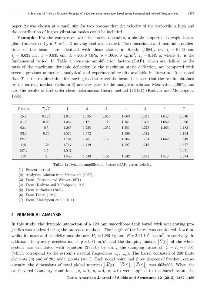
paper Δt was chosen at a small size for two reasons that the velocity of the projectile is high and the contribution of higher vibration modes could be included. Example: For the comparison with the previous studies, a simple supported isotropic beam-plate transversed by a F 4.4 N moving load was studied. The dimensional and material specifica-tions of the beam are identical with those chosen in Reddy (1984), i.e. xl 10.36 cm; yl 0.635 cm , h 0.635 cm, E 206.8 GPa, 10686.9 kg/m3, fT 8.149 s, where fT is the fundamental period. In Table 1, dynamic amplification factors (DAF), which are defined as the ratio of the maximum dynamic deflection to the maximum static deflection, are compared with several previous numerical, analytical and experimental results available in literature. It is noted that T is the required time for moving load to travel the beam. It is seen that the results obtained by the current method (column 3) are very close to the analytical solution Meirovitch (1967), and also the results of first order shear deformation theory method (FSDT) (Kadivar and Mohebpour, 1998).
V (m/s) fT T 1 2 3 4 5 6 7
15.6 0.125 1.040 1.025 1.055 1.063 1.045 1.042 1.040 31.2 0.25 1.352 1.121 1.112 1.151 1.350 1.082 1.090 62.4 0.5 1.265 1.258 1.252 1.281 1.273 1.266 1.183 93.6 0.75 1.574 1.572 - 1.586 1.572 - 1.194 124.8 1 1.704 1.701 1.7 1.704 1.704 1.662 1.549 156 1.25 1.717 1.719 - 1.727 1.716 - 1.527
187.2 1.5 1.547 - - - - - 1.471 250 2 1.543 1.548 1.54 1.542 1.542 1.518 1.374
Table 1: Dynamic amplification factors (DAF) versus velocity. (1) Present method. (2) Analytical solution from Meirovitch (1967). (3) From (Yoshida and Weaver, 1971). (4) From (Kadivar and Mohebpour, 1998). (5) From Michaltsos (2002). (6) From Taheri (1987). (7) From (Mohebpour et al., 2011).
4 NUMERICAL ANALYSIS
In this study, the dynamic interaction of a 120 mm smoothbore tank barrel with accelerating pro-jectiles was analysed using the proposed method. The length of the barrel was considered L 6 m, while, its mass and elasticity modules are bM 1280 kg and E 2.11x10¹¹ kg/m2, respectively. In addition, the gravity acceleration is g 9.81 m/s2, and the damping matrix ( )C t of the whole system was calculated with equation (27.a-b) by using the damping ratios of 1 2 0.005 (which correspond to the system’s natural frequencies 1 , 2 ). The barrel consisted of 200 finite elements (n) and of 201 nodal points (n+1). Each nodal point had three degrees of freedom; conse-quently, the dimensions of total global matrices ( )M t , ( )C t , ( )K t was 603x603. When the cantilevered boundary conditions ( 1u 0, 2u 0, 3u 0) were applied to the barrel beam, the
Latin American Journal of Solids and Structures 12 (2015) 1462-1486
1475 I. Esen and M.A. Koç / Dynamic Response of a 120 mm smoothbore tank barrel during horizontal and inclined firing positions
global matrices of the barrel decreased to the dimensions of 600x600, while the global force vector ( ( )F t ) decreased to the dimensions of 600x1. The inner pressure in the barrel, as a result of rap-idly expanding combustion gases of gunpowder, is time-dependent (Alexander, 2008); consequently, the acceleration of the projectile motion within the barrel is time-dependent as well. To reduce the complexity of calculations in the current study regarding the time-dependent acceleration, an aver-age acceleration was used for the motion of the projectile within the barrel. In this context, the average acceleration ma of the projectile was calculated by using the equation 2 2m exta v L , where extv is the projectile’s exit velocity from the barrel.
4.1 The effect of the projectile’s exit velocity from the barrel
To evaluate the effect of the projectile’s exit velocity from the barrel on the barrel vibrations, the motion equation (Eq. 23) was calculated for different velocities according to a projectile mass of
pm 20 kg, an angle of 0 between the barrel and the ground, and a time step of t x
-61 10 s . Figures 5a and 5b provide the vertical and longitudinal displacements of the muzzle on the global coordinate plane ( , z x ) at different projectile exit velocities ( extv 1000, 1500, 2000, 2500, and 3000 m/s). Since an increase in the projectile exit velocity is associated with a shorter exit time ( extt ), in this study a dimensionless time (also it can be treated as dimensionless position of the projectile in the barrel) px t L is used. As shown in Figure 5, for exit velocities of 1000, 1500, 2000, 2500, and 3000 m/s, the average accelerations of the projectile were 1.66x10⁵, 3.75x10⁵, 6.66x10⁵, 1.040x10⁶ and 1.5x10⁶ m/s2, respectively; while the maximum vertical displacement ( z ) of the muzzle (barrel tip) on the global coordinate plane at these velocity values were 0.69, 1.65, 2.98, 4.9, and 7.4 mm, respectively. These results and observations can be explained by the increase in the projectile’s average acceleration that is caused by the increase in the projectile’s exit velocity, and the associated increases in the projectile’s Coriolis and centripetal forces on the barrel. Alt-hough the increase in projectile’s exit velocity appears to have a negative effect on the barrel vibra-tions and target sensitivity, the increase in velocity is also of critical importance for the weapon’s destructive power and target acquisition (Littlefield et al., 2002). For more results of the effect of the exit velocity of the projectile, Figure 6 shows the tip deflections of the barrel for a projectile mass of 20 kg and the velocities from 100 to 12000 m/s with an increase of 100 m/s. The dynamic behavior of the barrel was very affected by exit velocity, and the tip deflection of the barrel shows a quadratic growth up to 3000 m/s exit velocity, then it shows a decrease in increment up to a specif-ic velocity, i.e., 5400 m/s when it gets the maximum. After the maximum it decreased symmetri-cally as shown from Figure 6. The reason of this behaviour will be discussed in the next sections; where the effects of Coriolis and inertial forces will be given. For more information one can also refer to (Oguamanam et al., 1998; Esen, 2011).
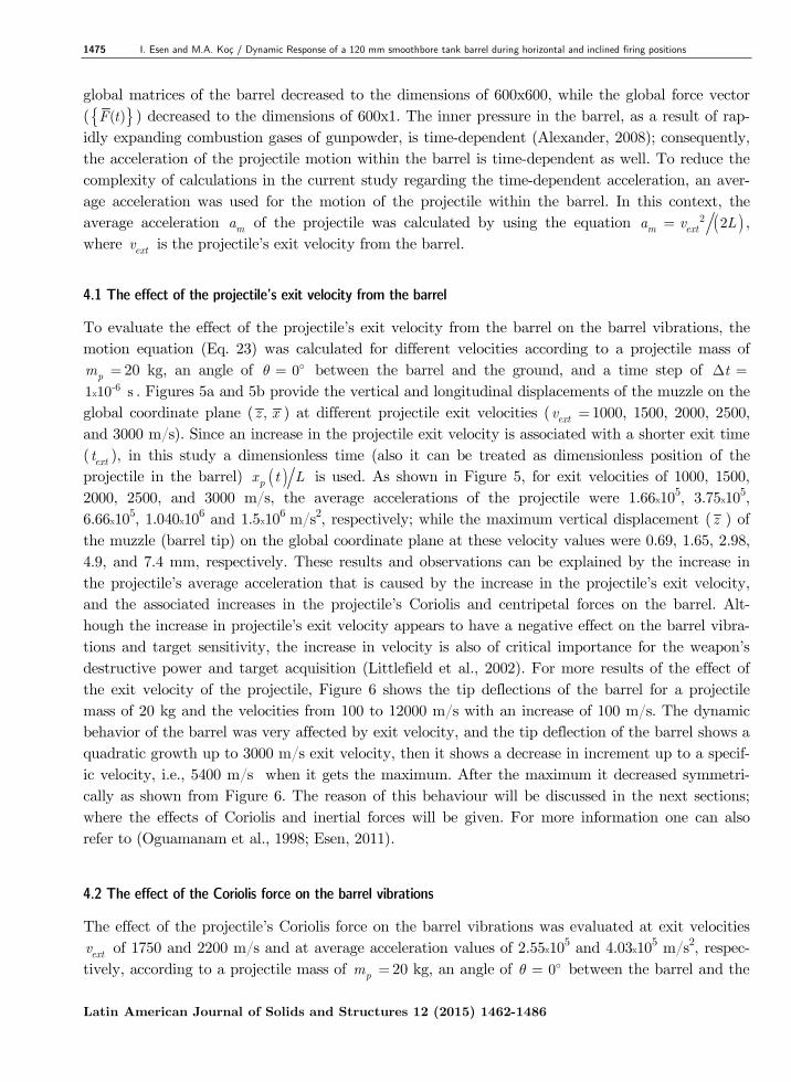
4.2 The effect of the Coriolis force on the barrel vibrations
The effect of the projectile’s Coriolis force on the barrel vibrations was evaluated at exit velocities extv of 1750 and 2200 m/s and at average acceleration values of 2.55x10⁵ and 4.03x10⁵ m/s2, respec-
tively, according to a projectile mass of pm 20 kg, an angle of 0 between the barrel and the
Latin American Journal of Solids and Structures 12 (2015) 1462-1486

I. Esen and M.A. Koç / Dynamic Response of a 120 mm smoothbore tank barrel during horizontal and inclined firing positions 1476
�
Figure 5: Displacements of the barrel tip for projectile mass pm 20 kg, time step size t 1x10⁻⁶ s and barrel
inclination angle 0 subjected to different exit velocity (a) Vertical ( z ), (b) Horizontal ( x ) displacement.
Figure 6: Maximum tip deflections of the barrel
ground, and a time step of t 1x10⁻⁶ s. The Coriolis force of the interaction between the barrel and projectile is represented by the equivalent damping matrix
6x6c . For this reason, this effect
will be ignored when the damping matrix 6x6
c of the projectile is taken as zero (6x6
0c ). When the Coriolis Effect is taken into account, the results of the analyses for both the axial (x ) and the radial ( z ) vibrations of the barrel on the global coordinate system are given in Figure 7. Any increase in the velocity, decreases the tip deflection of the barrel as can be seen from Figure 7. This observation is in agreement with the study Wu (2005). Furthermore, in equation (16.b), the increase in projectile velocity led to an increase in the value for the 2 pm v t expression, which in turn resulted in a higher Coriolis effect. Another subject here is that Eq. (16.b) has the multiplica-tions of the shape functions in (13) by their first order spatial derivatives ( i jN N ) that these terms also affect the Coriolis force.
Latin American Journal of Solids and Structures 12 (2015) 1462-1486
1477 I. Esen and M.A. Koç / Dynamic Response of a 120 mm smoothbore tank barrel during horizontal and inclined firing positions
0 0.1 0.2 0.3 0.4 0.5 0.6 0.7 0.8 0.9 10
1
2
3
4x 10⁻³
xp(t)/L
Ver
tical
def
lect
ion
of th
e ba
rrel t
ip (m
).
0 0.1 0.2 0.3 0.4 0.5 0.6 0.7 0.8 0.9 1-15
-10
-5
0
5x 10⁻⁷
xp(t)/L
Hor
izon
tol d
ispl
acem
ent o
f the
ba
rrel t
ip (m
).
Figure 7: Coriolis effect upon barrel tip displacement for time step size t 1x10⁻⁶, projectile mass pm 20 kg,
and barrel inclined angle 0 (a) Vertical ( z ), (b) Horizontal ( x ) displacements. 4.3 The effect of the inertial force on the barrel vibrations
The effect of the inertial force of the projectile (as represented by a finite element) on the barrel’s vibrations was calculated at an exit velocity extv of 1750 m/s and an average acceleration value of 2.55x10⁵ m/s2, according to projectile masses of pm 20 and 30 kg, an angle of 0 between the barrel and the ground, and a time step of t 1x10⁻⁶ s. The inertial force of the interaction of the barrel and projectile is represented by the mass matrix
6x6m . Therefore, this effect can be ignored
by using a mass matrix 6x6
0m . The graph in Figure 8 provides the solutions/results obtained by first taking into account all of the characteristic matrices of the projectile and barrel interaction (
6x6m ,
6x6c ,
6x6k ) for projectile masses 20 and 30 kg, and then by taking into account the
damping matrix 6x6
0m . The results are illustrated for both the axial (x ) and the radial (z ) vibrations of the barrel on the global coordinate system. As shown in Figure 8, taking into account the inertial effect caused the vertical displacement of the barrel tip to increase considerably, while causing the axial displacement to increase slightly. A similar relationship was observed in the stud-ies (Oguamanam et al., 1998; Wu, 2008; Esen, 2011). 4.4 The effect of the inclination angle of the barrel
To evaluate the effect of the barrel’s angle with the ground on the axial (x ) and transverse ( z ) vibrations at the muzzle; the motion equation was solved for different barrel angles according to a projectile mass of pm 20 kg, a projectile exit velocity of extv 1750 m/s, an average projectile acceleration ( ma ) of 2.55x10⁵ m/s2, and a time step of t 1x10⁻⁶ s. As shown in Figure 9, an in-crease in the angle between the barrel and the ground was associated with a decrease in the transverse displacement ( z ) and an increase in the axial displacement (x ) on the global coordinate plane. This observation is in agreement with the study in Wu (2005).
Latin American Journal of Solids and Structures 12 (2015) 1462-1486

I. Esen and M.A. Koç / Dynamic Response of a 120 mm smoothbore tank barrel during horizontal and inclined firing positions 1478
Figure 8: Inertial force effect upon barrel tip displacement for time step size t 1x10⁻⁶, projectile mass pm 20
and 30 kg, and barrel inclined angle 0 (a) Vertical ( z ), (b) Horizontal ( x ) displacements.
0 0.2 0.4 0.6 0.8 10
0.5
1
1.5
2
2.5x 10⁻³
°°°
0 0.2 0.4 0.6 0.8 1-1
-0.5
0
0.5
1
1.5x 10
-5
0 °15 °30 °
Figure 9: (a) Vertical ( z ), (b) Horizontal ( x ) displacements of the barrel tip for projectile mass pm 20 kg, time
step size t 1x10⁻⁶ s and different barrel inclined angle . 4.5 The effect of the projectile mass on the barrel vibrations
The effect of the projectile mass on the radial ( z ) and axial (x ) vibrations of the muzzle was eval-uated for projectile masses ( pm ) of 16, 20, and 24 kg, according to a time step of t 1x10⁻⁶ s, an projectile exit velocity of extv 1750 m/s, an average acceleration of ( ma ) 2.55x10⁵ m/s2 for the projectile, and an angle of 0 between the barrel and the ground. Figure 10 shows the solutions obtained based on calculations performed with different projectile mass values. The increase in pro-jectile mass was associated with an increase in both axial (x ) and radial ( z ) vibrations. This ob-servation can be explained by the increase in the axial force x p cf m a and the transverse force
Latin American Journal of Solids and Structures 12 (2015) 1462-1486

1479 I. Esen and M.A. Koç / Dynamic Response of a 120 mm smoothbore tank barrel during horizontal and inclined firing positions
y pf m g that is associated with the increase in projectile mass. A similar relationship was ob-served in the studies Esen (2011), Michaltsos et al. (1996) and Michaltsos and Kounadis (2001). This can be an expected result that any increase in the mass, increases both inertial and gravita-tional forces. But, unlike the effect of the velocity, the deflection shape of the barrel remains similar for each additional mass. One can realize this phenomena when, especially, the axial vibrations of the barrel in Figures 7 and 10 are analysed.
0 0.2 0.4 0.6 0.8 10
0.5
1
1.5
2
2.5
3x 10⁻³
mp=16 kg
mp=20 kg
mp=24 kg
0 0.2 0.4 0.6 0.8 1-12
-10
-8
-6
-4
-2
0
2x 10⁻⁷
Figure 10: Vertical ( z ), b) horizontal ( x ) displacements of the barrel tip for time step size t 1x10⁻⁶ s and
barrel inclined angle 0 subjected to different projectile mass pm . 4.6 The forced and free vibrations of the barrel
To determine the effect of structural damping on ( z ) vibrations of the barrel tip, the equation was solved according to a solution period t 0.15 s, a time step of t 3.42x10⁻⁵ s, a projectile mass of
pm 20 kg, a projectile exit velocity of extv 1750 m/s, and an angle of 0 between the barrel and the ground. When the projectile has left the barrel px t L , the mass, stiffness and damping matrices (
6x6m ,
6x6c ,
6x6k ) and the force vector (t)F
are considered to be equal to zero, which allows the barrel to display free vibrations. As shown in Figure 11, the projectile exited the barrel in 0.007 s, after which the barrel vibrates freely. As illustrated on the graph, the free vibra-tion of the barrel had completely dampened 0.15 s after the firing when using the damping ratios of
1 2 0.005 . 4.7 Serial firing effects
The axial (x ) and radial ( z ) muzzle vibrations caused by the interaction between the projectile and the barrel during a single firing of the weapon are shown in Figures 5-11. In this section, the vibrations caused by the serial/repeated firing of the weapon system were considered and evaluated. For the effect of none zero initial conditions of the barrel, i.e., a second firing performed before the dampening of vibrations from a first firing, the effect of successive firing was modelled and analysed. Assuming that, fn represents the total number of firing within time t, the time period between each firing is calculated with 1g ft t n . Figure 12 shows serial firing model of the 120 mm smoothbore barrel. In this model gX distance between two consecutively fired projectiles is ex-pressed as follows: Latin American Journal of Solids and Structures 12 (2015) 1462-1486

I. Esen and M.A. Koç / Dynamic Response of a 120 mm smoothbore tank barrel during horizontal and inclined firing positions 1480
2
0 2g g m gX v t a t (35)
0 0.02 0.04 0.06 0.08 0.1 0.12 0.14-2
-1.5
-1
-0.5
0
0.5
1
1.5
2
2.5x 10⁻³
Figure 11: Vertical ( z ) displacements of the barrel tip for time step size t 3.42x10⁻⁵ s
and barrel inclined angle 0 .
mpx
z
Xg
v (t)am , m
O
z
Figure 12: Serial firing model of the barrel.
4.7.1 Situation 1: gt 0.02 s, fn 2
In this scenario; the effect of residual vibration energy of the barrel from a previous firing on the following firing when gt was 0.02 s between the two firings was calculated according to a time step of t 5x10⁻⁵ s, an angle of 0 between the barrel and the ground, an exit velocity of the pro-jectile extv 1750 m/s, an average acceleration value of ma 2.55x10⁵ m/s2 for the projectile, and projectile masses of pm 20 and 24 kg. As shown in Figure 13, the maximum vertical tip (muzzle) displacements ( z ) that occurred on the global coordinate plane with the 20 and 24 kg projectiles were 0.0022 and 0.0026 m, respectively, during the first firing; and 0.0026 and 0.0031 m, respective-ly, during the second firing. These observations indicated that the muzzle displacement with the 20 kg projectiles increased by 18% during the second firing in comparison to the first firing, while the increase observed during the second firing with the 24 kg projectiles was 19%. The reason for this increase is that the second firing is performed before the effect of the first firing has not been damp-ened yet.
Latin American Journal of Solids and Structures 12 (2015) 1462-1486

1481 I. Esen and M.A. Koç / Dynamic Response of a 120 mm smoothbore tank barrel during horizontal and inclined firing positions
0 0.02 0.04 0.06 0.08 0.1
-2
-1
0
1
2
3
4x 10⁻³
Time (s)
Figure 13: Vertical ( z ) displacements of the barrel tip for projectile mass pm 20 kg, time step size t 0.2x10-
4 s, barrel inclined angle 0 and second projectile firing time 2t 0.02 s. 4.7.2 Situation 2: gt 0.02 s, fn 4
In this scenario, the effect of barrel vibrations caused by four consecutive firings with gt 0.02 was calculated according to a time step of t 5x10⁻⁵ s, an angle of 0 between the barrel and the ground, an exit velocity of the projectile extv 1750 m/s, an average acceleration value of
ma 2.55x10⁵ m/s2 for the projectile, and projectile masses of pm 20 and 24 kg. As shown in Figure 14, the maximum vertical muzzle displacement ( z ) that occurred on the global coordinate plane with the 20 and 24 kg projectiles was 0.0022 and 0.0026 m, respectively, during the first fir-ing; 0.0026 and 0.0031 m, respectively, during the second firing; 0.0025 and 0.003 m, respectively, during the third firing; and 0.0023 and 0.0027 m, respectively, during the fourth firing.
0 0.01 0.02 0.03 0.04 0.05 0.06 0.07 0.08-3
-2
-1
0
1
2
3
4x 10
-3
mp=20 kg
mp=24 kg
Firing time ofthe secondprojectile
Firing time ofthe fourthprojectile
Firing time of thethird projectile
Figure 14: Vertical ( z ) displacements of the barrel tip for projectile mass pm 20 kg, time step size
t 0.2x10⁻⁴ s, barrel inclined angle 0 and second, third, fourth projectiles firing time respectively 2t 0.02 s, 3t 0.04 s, 4t 0.06 s.
Latin American Journal of Solids and Structures 12 (2015) 1462-1486

I. Esen and M.A. Koç / Dynamic Response of a 120 mm smoothbore tank barrel during horizontal and inclined firing positions 1482
4.7.3 Situation 3: g extt t , fn 2
In this scenario, the effect of two firings in which the gt between the firings was equal to the exit time of the projectile during the first firing was calculated according to a time step of t 5x10⁻⁵ s, an angle of 0 between the barrel and the ground, an exit velocity ( extv ) of 1750 m/s, an average acceleration value of ma 255,000 m/s2 for the projectile, and projectile masses of pm 20 and 24 kg. As shown in Figure 15, the maximum vertical muzzle displacement ( z ) that occurred on the global coordinate plane with the 20 and 24 kg projectiles was 0.0022 and 0.0026 m, respectively, during the first firing; and 0.0032 and 0.0039 m, respectively, during the second firing. These obser-vations indicated that the muzzle displacement with the 20 kg projectiles increased by 45% during the second firing in comparison to the first firing, while the increase observed with the 24 kg projec-tiles was 50%.
0 0.002 0.004 0.006 0.008 0.01 0.012 0.0140
0.5
1
1.5
2
2.5
3
3.5
4
4.5
5x 10
-3
Figure 15: Vertical ( z ) displacements of the barrel tip for projectile masses of pm 20 and 24 kg, barrel inclina-
tion angle 0 and second projectile firing time 2t 0.00648 s (when the first projectile leaves the barrel).
5 CONCLUSION
In this study, the dynamic interaction between a projectile and a barrel was modelled and investi-gated. This interaction was obtained developing a new method in which the projectile is represented as a time dependent equivalent finite element in the finite element model of the whole system. Tak-ing into account the inertia, Coriolis, and centripetal forces exerted by the projectile onto the bar-rel, the equivalent finite element is formed using the relations between the deflection function of a thin beam and the nodal deflections and forces of the beam element that carries the projectile at time t. In addition, when the barrel was moved from the global coordinate plane to a different local coordinate plane, the property matrices of the barrel and projectile were carried to the new coordi-nate system by using a transformation matrix. A dynamic analysis was also performed in case the barrel was at an angle from the ground level. It was determined that the increase in the inclination angle of the barrel increased the axial vibrations of the barrel, while reducing its radial vibrations.
Latin American Journal of Solids and Structures 12 (2015) 1462-1486

1483 I. Esen and M.A. Koç / Dynamic Response of a 120 mm smoothbore tank barrel during horizontal and inclined firing positions
During the study, it was observed that the amplitude of barrel muzzle’s displacement increased in parallel to the increase in the projectile mass and velocity. The study also demonstrated the effects of the inertial centripetal and Coriolis forces of the projectile on the barrel tip displacements. It was observed that the projectile’s inertia force increased the vertical vibrations of the barrel tip, while the Coriolis and centripetal forces reduced the tip deflections. Because the Coriolis force is repre-sented as a damping matrix, and the Centripetal force is represented as the stiffness matrix in the finite-element interaction of the projectile and barrel. In addition, three different scenarios were evaluated to determine how the serial (or consecutive) firing of the weapon system affected the bar-rel vibrations. In the first of these scenarios, two consecutive fires were shot with a time period of 0.02 s between the two firings. In this scenario, it was observed that the maximum tip displacement during the second firing was approximately 20% greater than that of the first firing. In addition, this increase in displacement was observed to be proportional to the mass of the projectile. In the second scenario, four consecutive shots were fired once again at intervals of 0.02 s; the results relat-ed to these firings are shown in Table 2. As an extreme case, in the third scenario, two shots were once again fired with the second firing being performed at the moment the first projectile was exit-ing the barrel. In this scenario, it was observed that the maximum vertical tip displacement of the second firing was 45% greater than the displacement in the first firing. Although this scenario is not possible or feasible for present-day conventional weapons, such a scenario was considered to ensure scientific consistency in the study.
Maximum barrel tip deflection at global ( z ) direction (mm)
First Firing Second Firing Third Firing Fourth Firing
pm 20 kg 2.2 2.6 2.5 2.3
pm 24 kg 2.6 3.1 3 2.7
Table 2: Maximum tip deflection of the barrel during four serial firing. Information obtained within the scope of this study will potentially contribute to future studies on various subjects, such as the design of optimum barrel geometry, the development of firing control algorithms for better firing sensitivity, the design of barrel vibration absorbers, and automatic fir-ing. Engineering applications in defence industries are generally more important than their other usages, thus, the studies in this area are kept confidential, and they need higher research and devel-opment costs due to the request of the firm tolerances and precise operations. The significance of vibrations of structures and their prevention from vibration in terms of correct working and service life of equipment is obvious. First of all, during the design the vibration behaviour of the equipment should be analysed in order to take the necessary measures to protect the mechanical equipment from vibration. Moreover, this proposed method can be used for both in development of a new weapon and analysing the dynamic behaviour of an existing barrel in order to control the vibrations by an active or passive vibration absorber. Carrying out the analysis of many situations may reduce the number of the time-consuming and costly experimental studies needed to practice. Also, this study can provide theoretically sufficient data for weapon automation software for compensation
Latin American Journal of Solids and Structures 12 (2015) 1462-1486

I. Esen and M.A. Koç / Dynamic Response of a 120 mm smoothbore tank barrel during horizontal and inclined firing positions 1484
tunings by predicting the nonlinear behaviour and defections of the barrel for different types of projectile that have different velocity and mass properties. This can be done by adding a pre-control algorithm to the automation software of a weapon, and before the firing, the automation system can predict the amount of deflections of the barrel and do necessary compensations, and in this way a more accurate targeting may be obtained. Support flexibility is another parameter that affects target accuracy. In this study the support accepted as fixed in order to examine the dynamic interaction of the accelerating projectile and barrel. If one need to study the effect of flexible support on firing accuracy, using the method given in this study and including any desired flexible support degree of freedom, in that case the effect of flexible support can be obtained with the effect of dynamic interaction of the projectile and the barrel. Moreover, the support flexibility that should be studied requires more realistic parameters of the tank to be considered. Further, for more accurate parameters of support flexibility, more exper-imental and theoretical works should be done. Especially, recoiling motion of the barrel, the pitch-ing motion of the whole tank body, and the properties of ground and pallets, etc., should be precise-ly determined for an acceptable results of analysis. In that case for flexible supports there should be many cases of analysis in order to obtain a complete behaviour of the whole system of tank body and barrel assembly. Furthermore, there should be many other cases of pallets and ground interac-tions. In this study in order to emphasize the effect of the projectile barrel interaction, and not to extend the present study to the all cases of firing accuracy, it is considered that the barrel has a cantilevered boundary conditions. Furthermore, one can also further extend this method to vibration engineering of some other problems such as high-speed precision machining, high-speed rail road design and cable transport etc. In this way, important time and cost benefits can be obtained for the suitable design of many vibrating engineering systems under the effect of accelerating masses. References Alexander, J.E., (2008). AGS gun and projectile dynamics modeling correlation to test data. US Army Armament Systems Division proceedings of 26th IMAC: Conference and Exposition on Structural Dynamics, Orlando, Florida, New York, 4-7 February.
Awodola, T.O., (2014). Flexural motions under moving masses of elastically supported rectangular plates resting on variable winkler elastic foundation. Latin American Journal of Solids and Structures 11: 1515-1540.
Balla, J., (2011). Dynamics of mounted automatic cannon on track vehicle. Mathematical Models and Methods in Applied Sciences 5(3): 423-432. Bathe, K.J., (1996). Finite element procedures. 2. Ed. Prentice Hall, New Jersey.
Bulut, H., Kelesoglu, Ö., (2010). Comparing numerical methods for response of beams with moving mass. Advances in Engineering Software 41: 976-980. Cifuentes, A.O., (1989). Dynamic response of a beam excited by a moving mass. Finite Elements in Analysis and Design 5: 237– 46. Clough, R.W., Penzien, J., (2003). Dynamics of structures. 3. Ed. Berkeley, New York.
Dehestani, M., Mofid, M., Vafai, A., (2009). Investigation of critical influential speed for moving mass problems on beams. Applied Mathematical Modelling 33: 3885-3895.
Dyniewicz, B., Bajer, C., (2012). New consistent numerical modelling of a travelling accelerating concentrated mass. World Journal of Mechanics 2(6): 281-287.
Latin American Journal of Solids and Structures 12 (2015) 1462-1486

1485 I. Esen and M.A. Koç / Dynamic Response of a 120 mm smoothbore tank barrel during horizontal and inclined firing positions
Esen, I., (2011). Dynamic response of a beam due to an accelerating moving mass using moving finite element ap-proximation. Math. Comput. Appl. 16(1): 171-182.
Esen, I., (2013). A new finite element for transverse vibration of rectangular thin plates under a moving mass. Finite Elements in Analysis and Design 66: 26-35.
Esen, I., Koç, M.A., Mulcar, H., (2012). 35mm uçak savar namlusunun atış esnasındaki dinamik analizi. Timak 2012: 3. Ulusal Tasarım İmalat ve Analiz Kongresi; 29-30 Kasım 2012; Balıkesir, Turkey, pp. 275-290.
Esen, I., Koç, M.A., (2013). 35 mm Uçaksavar Topu Namlusu için Titreşim Absorberi Tasarımı ve Genetik Algorit-ma ile Optimizasyonu, Otomatik Kontrol Ulusal Toplantısı, TOK2013, 26-28 Eylül 2013, Malatya, Türkiye, pp. 513-518. Fryba, L., (1999). Vibration solids and structures under moving loads. 3. Ed. Thomas Telford House, London.
Kadivar, M.H., Mohebpour, S.R., (1998). Finite element dynamic analysis of unsymmetric composite laminated beams with shear effect and rotary inertia under the action of moving loads. Finite Elements in Analysis and Design 29: 259. Kahya, V., (2012). Dynamic analysis of laminated composite beams under moving loads using finite element method. Nuclear Engineering and Design 243: 41-48. Koç, M.A., Esen, I., (2013). Dynamic analysis of 35 mm antiaircraft barrel during shooting. MSc Thesis, Karabuk University, Karabük, Turkey. Lee, H.P., (1996a). The dynamic response of a Timoshenko beam subjected to a moving mass. Journal of Sound and Vibration 198(2): 249-256. Lee, H.P., (1996b). Transverse vibration of a Timoshenko beam acted upon by an accelerating mass. Applied Acous-tics 47(4): 319-330. Littlefield, A., Kathe, E., Messier, R., Olsen, K., (1997). Gun barrel vibration absorber to increase accuracy. US Army Armament Research, New York, 19970606150: 1-13.
Littlefield A., Kathe E., Messier R., Olsen, K., (2002). Design and validation of a gun barrel vibration absorber. US Army Armament Research, New York, 20020304089: 2-23. Meirovitch, L., (1967). Analytical methods in vibrations. The Macmillan Company, New York. Michaltsos, G.T., Sophianopoulos, D., Kounadis, A.N., (1996). The effect of a moving mass and other parameters on the dynamic response of a simply supported beam. Journal of Sound and Vibration 191: 357-362. Michaltsos, G.T., Kounadis, A.N., (2001). The effects of centripetal and Coriolis forces on the dynamic response of light bridges under moving loads. Journal of Vibration and Control 7: 315-326. Michaltsos, G.T., (2002). Dynamic behaviour of a single-span beam subjected to loads moving with variable speeds. Journal of Sound and Vibration 258(2): 359-372. Mohebpour, S.R., Malekzadeh, P., Ahmadzadeh, A.A., (2011). Dynamic analysis of laminated composite plates sub-jected to a moving oscillator by FEM. Composite Structures 93: 1574–1583.
Nikkhoo, A., Rofooei, F.R., Shadnam, M.R., (2007). Dynamic behaviour and modal control of beams under moving mass. Journal of Sound and Vibration 306: 712-724.
Oguamanam, D.C.D., Hansen, J.S., Heppler, G.R., (1998). Dynamic response of an overhead crane system. Journal of Sound and Vibration 213(5): 889–906. Omolofe, B., (2013). Deflection profile analysis of beams on two-parameter elastic subgrade. Latin American Journal of Solids and Structures 10: 263–282. Oni, S.T., Awodola, T.O., (2010). Dynamic response of an elastically supported non-prismatic beam on variable elastic foundation. Latin American Journal of Solids and Structures 7: 3– 20. Przemieniecki, J.S., (1985). Theory of Matrix Structural Analysis. McGraw-Hill, New York. Sharbati, E., Szyszkowski, W., (2011). A new FEM approach for analysis of beams with relative motions of masses. Finite Elements in Analysis and Design 47: 1047-1057.
Latin American Journal of Solids and Structures 12 (2015) 1462-1486
I. Esen and M.A. Koç / Dynamic Response of a 120 mm smoothbore tank barrel during horizontal and inclined firing positions 1486
Reddy, J.N., (1984). Energy and variational methods in applieds mechanics. John Wiley and Sons, New York.
Taheri, M.R., (1987). Dynamic response of plates to moving loads, structural impedance and finite element methods. PhD thesis, Purdue University, IN.
Tawfik, M., (2008). Dynamics and stability of stepped gun-barrels with moving bullets. Advances in Acoustics and Vibration, Article ID 483857 (6 pages): DOI 10.1155/2008/483857.
Wang, Y.M., (2009). The transient dynamics of a moving accelerating/decelerating mass travelling on a periodic-array non-homogeneous composite beam. European Journal of Mechanics – A Solids 28: 827-840.
Wilson, E.L., (2002). Static and dynamic analysis of structures. Computers and Structures Inc., New York.
Wu, J.J., Whittaker, A.R., Cartmell, M.P., (2001). Dynamic responses of structures to moving bodies combined finite element and analytical methods. International Journal of Mechanical Sciences 43: 2555-2579.
Wu, J.J., (2005). Dynamic Analysis of an inclined beam due to moving loads. Journal of Sound and Vibration 288: 107-131.
Wu, J.J., (2008). Transverse and longitudinal vibrations of a frame structure due to a moving trolley and the hoisted object using moving finite element. International Journal of Mechanical Sciences 50: 613–625.
Yoshida, D.M., Weaver, W., (1971). Finite element analysis of beams and plates with moving loads. Publ. Interna-tional Association for Bridges and Structural Engineers 31: 179–195.
Latin American Journal of Solids and Structures 12 (2015) 1462-1486

![DBK386WD+ K6360++ -RO&EN-4578333313...al]i factori atmosferici. Instalarea corectInstalarea corect\\\\ este esen]ial este esen]ial este esen]ial\\\\ pentru a pentru a asigura func]ionarea](https://img.pdfslide.net/doc/110x75/5e5218b8e5642b558178902b/dbk386wd-k6360-roen-4578333313-ali-factori-atmosferici-instalarea.jpg)