Embed Size (px)
Citation preview
8/10/2019 Dynamic Simulation Example Invensys.pdf
http://slidepdf.com/reader/full/dynamic-simulation-example-invensyspdf 1/6
Applic at ionSolut ion
Summary
ynamic simulation can be
sed to simulate a typical
istillation column or
actionator relief scenario
o calculate the column
elief load more accurately
han using conventional
methods, while
maintaining an acceptable
margin of safety.
Business Value
Eliminate the need foradditional relief valves
on unit revamp or
debottlenecking projects
Eliminate or reduce the
cost for additional fl are
system piping for refinery
expansion projects
Increase throughput
through units that are
constrained by relief
capacity
INTRODUCTIONDynamic simulation can simulate a typical distillation column or fractionator reliefscenario (such as cooling water failure, partial power failure, and total power failure).The objective of the analysis is to calculate the column relief load more accuratelythan using conventional methods while maintaining an acceptable margin ofsafety. The peak relief ow may then be used to size relief valves or used within anoverall are analysis to determine relief valve back pressures. In most cases, theuse of dynamic simulation can reduce the need for additional relief valves or aresystem expansion. This example discusses how dynamic simulation can reduce thecalculated relief loads by 25% or more as compared with conventional calculations.
DYNAMIC SIMULATION BENEFITS SUMMARY • Eliminate the need for additional relief valves on unit revamp or debottlenecking
projects
• Eliminate or reduce the cost for additional are system piping for reneryexpansion projects
• Increase throughput on units that are constrained by relief capacity
DYNAMIC SIMULATION APPROACHConventional methods for calculating column relief loads are very conservativeand can lead to over-designed relief systems, unnecessary are, or are headerreplacements during unit revamp and debottlenecking projects.
Dynamic simulation provides an alternative to conventional calculation methods andprovides substantially lower relief loads. For fractionation towers with wide boilingranges, signicant are load reductions are possible. Dynamic simulation accounts
for the limited inventory of light components and the sensible heat required to boiloff the heavier components.
Dynamic simulation is consistent with the approach of API-521. API RP 521 Section3.3 (1995) has two components:
1. “For mixtures, light components are relieved before heavier components.” 2. “Change in vapor rate and molecular weights at various time intervals should be
investigated.“
Dynamic simulation provides a safe and documented alternative to conventional reliefload calculations methods that result in substantially lower calculated relief loads.
Dynamic Simulation Example:Column Relief Load Analysis
8/10/2019 Dynamic Simulation Example Invensys.pdf
http://slidepdf.com/reader/full/dynamic-simulation-example-invensyspdf 2/6
CONVENTIONAL APPROACHThe conventional approach used by many process designers is to use a heat balance method aroundthe entire column. If condenser cooling is lost, the heat balance is recalculated accordingly and the
net heat input is applied to a tray at or near the top of the column. The heat of vaporization is used tocalculate relief ow based on the following equation:
Where:W - Relief owf - Feed or product owh - Feed or product enthalpyQ - Reboiler or condenser duty
λ - Heat of vaporization
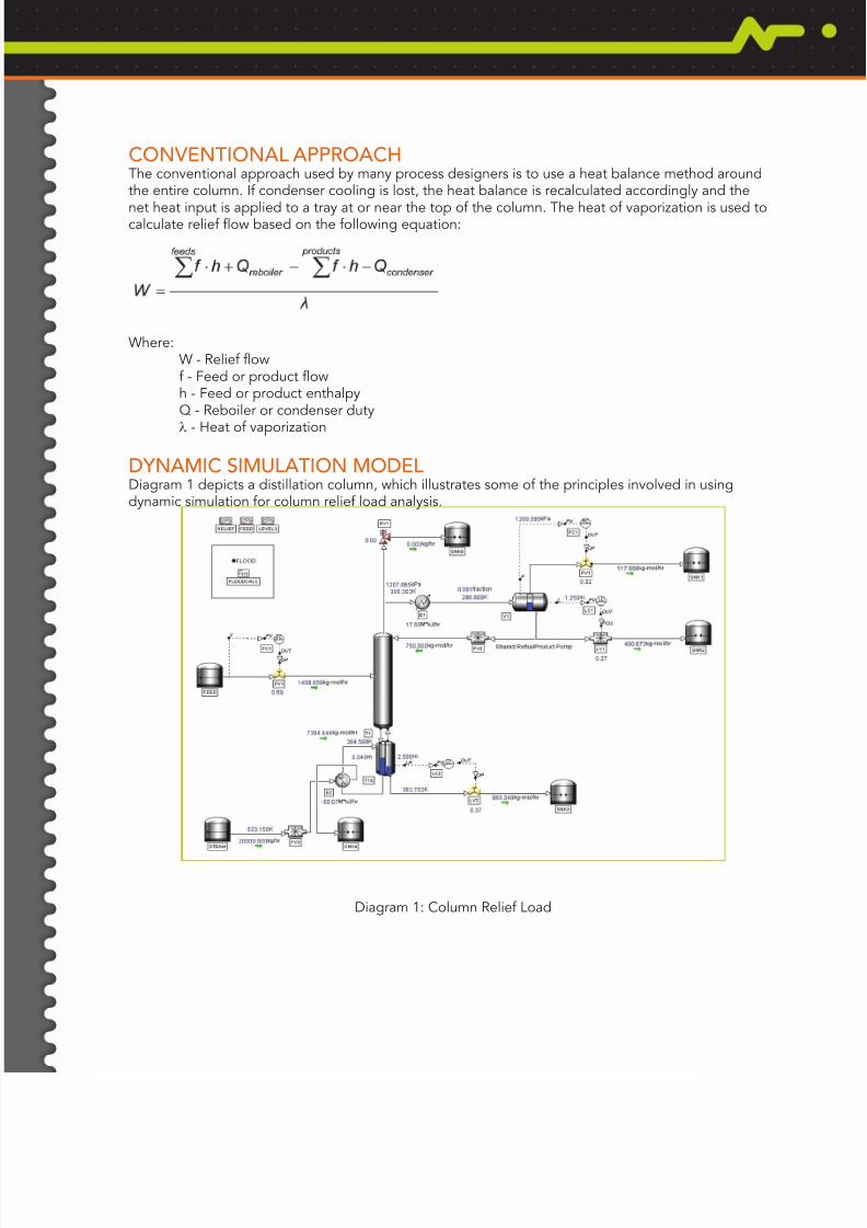
DYNAMIC SIMULATION MODELDiagram 1 depicts a distillation column, which illustrates some of the principles involved in usingdynamic simulation for column relief load analysis.
Diagram 1: Column Relief Load
8/10/2019 Dynamic Simulation Example Invensys.pdf
http://slidepdf.com/reader/full/dynamic-simulation-example-invensyspdf 3/6
The following assumptions were made in the development of this simulation model;
Tower• The DYNSIM® Tower Model includes both vapor and liquid holdup on each tray.• Tray liquid holdup assumes clear liquid height. This is a conservative assumption as it increases the
amount of volatile low boiling point components.• The Tower has the same number of theoretical stages as the steady state simulation. The inventory of
each theoretical stage is adjusted by the ratio of actual trays to theoretical stages.• A DYNSIM Separator simulates the column sump. The Separator includes an internal weir to simulate
the thermosyphon reboiler bafe. Accurately modeling the sump inventory is important as reboilerheat transfer rate reduces as the inventory is depleted.
Pumps and Valves• DYNSIM rigorously models pumps, valves, and controllers. However, there are simplied models
available for situations where not all the equipment data is available. For example, the DYNSIMStreamSet model simulates the overhead liquid product level control valve and reux ow control valve.
•
A DYNSIM Valve and PID simulate the feed ow control valve and ow controller. The rigorous valvemodel calculates the reduced feed ow to the column that may occur as the column pressure rises.
Condenser• The overhead condenser is modeled with an equation to reduce surface area when the overhead
accumulator oods.
Relief Valve• The DYNSIM Relief Valves are set to modulate rather than pop open. A modulating relief valve provides
the peak relief rate while holding the column pressure at a nearly constant rate as required to determinethe relief load. This is the preferred approach when determining a peak relief ow to use in an overallare system back pressure analysis or to size relief valves for a new column. Alternatively, the relief valvecan be pop acting based on the available relief valve orice area to determine if pressure rises above
the allowable accumulation (10% for single valves and 16% for multiple valves).
Controls• Per API Recommended Practice 521, controllers fail in their last positions unless their automatic
action increases the relief load. Many controllers are not required to be modeled and the simulationdoes not need to match the control conguration used in the actual plant.
• Reux cascade ow controller operates to keep a constant mass ow rate. The master controllers areassumed to not change the set point the slave controllers.
• The overhead pressure controller locks in position since its action to open on high pressure wouldreduce the relief valve load.
• Tray temperature controllers on reboiler steam are not required to be simulated since a temperatureincrease during relief would reduce reboiler heat transfer.
8/10/2019 Dynamic Simulation Example Invensys.pdf
http://slidepdf.com/reader/full/dynamic-simulation-example-invensyspdf 4/6
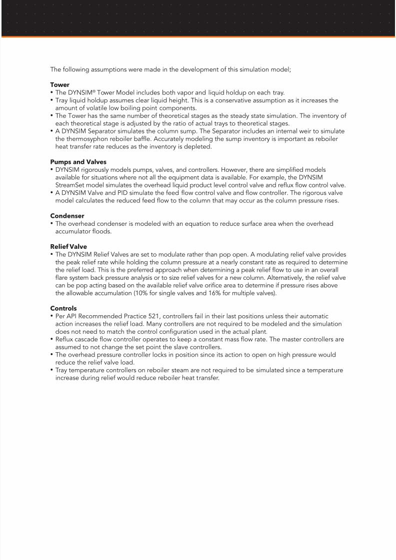
SCENARIO CASES AND RESULTSTable 1 summarizes the three relief scenarios and provides the results for the conventional calculationand peak DYNSIM relief ow. Table 2 shows the actual scenarios as implemented in the DYNSIM
Scenario utility.
Table 1: Scenario Cases and Results
Table 2: DYNSIM Scenarios
8/10/2019 Dynamic Simulation Example Invensys.pdf
http://slidepdf.com/reader/full/dynamic-simulation-example-invensyspdf 5/6
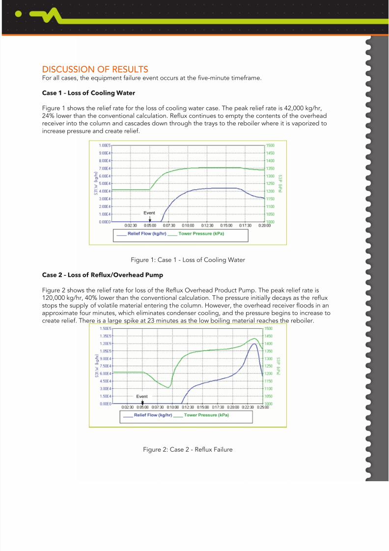
DISCUSSION OF RESULTSFor all cases, the equipment failure event occurs at the ve-minute timeframe.
Case 1 – Loss of Cooling Water
Figure 1 shows the relief rate for the loss of cooling water case. The peak relief rate is 42,000 kg/hr,24% lower than the conventional calculation. Reux continues to empty the contents of the overheadreceiver into the column and cascades down through the trays to the reboiler where it is vaporized toincrease pressure and create relief.
Figure 1: Case 1 - Loss of Cooling Water
Case 2 – Loss of Reflux/Overhead Pump
Figure 2 shows the relief rate for loss of the Reux Overhead Product Pump. The peak relief rate is120,000 kg/hr, 40% lower than the conventional calculation. The pressure initially decays as the reuxstops the supply of volatile material entering the column. However, the overhead receiver oods in anapproximate four minutes, which eliminates condenser cooling, and the pressure begins to increase tocreate relief. There is a large spike at 23 minutes as the low boiling material reaches the reboiler.
Figure 2: Case 2 - Reux Failure
8/10/2019 Dynamic Simulation Example Invensys.pdf
http://slidepdf.com/reader/full/dynamic-simulation-example-invensyspdf 6/6
Invensys, the Invensys logo, ArchestrA, Avantis, Eurotherm, Foxboro, IMServ, InFusion, SimSci-Esscor, Triconex, and Wonderware are trademarks of Invensys plc, its subsidiaries or afliates. All obrands and product names may be the trademarks or service marks of their representative owners.
© 2010 Invensys Systems, Inc. All rights reserved. No part of the material protected by this copyright may be reproduced or utilized in any form or by any means, electronic or mechanical, incluphotocopying, recording, broadcasting, or by any information storage and retrieval system, without permission in writing from Invensys Systems, Inc.
Invensys Operations Management • 5601 Granite Parkway III, #1000, Plano, TX 75024 • Tel: (469) 365-6400 • Fax: (469) 365-6401 • iom.invensys.com
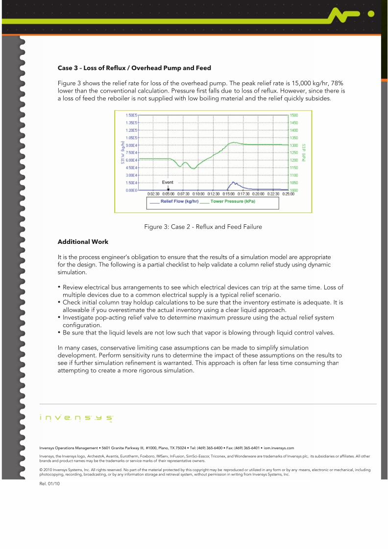
Case 3 – Loss of Reflux / Overhead Pump and Feed
Figure 3 shows the relief rate for loss of the overhead pump. The peak relief rate is 15,000 kg/hr, 78%lower than the conventional calculation. Pressure rst falls due to loss of reux. However, since there isa loss of feed the reboiler is not supplied with low boiling material and the relief quickly subsides.
Figure 3: Case 2 - Reux and Feed Failure
Additional Work
It is the process engineer’s obligation to ensure that the results of a simulation model are appropriatefor the design. The following is a partial checklist to help validate a column relief study using dynamicsimulation.
•Review electrical bus arrangements to see which electrical devices can trip at the same time. Loss ofmultiple devices due to a common electrical supply is a typical relief scenario.
• Check initial column tray holdup calculations to be sure that the inventory estimate is adequate. It isallowable if you overestimate the actual inventory using a clear liquid approach.
• Investigate pop-acting relief valve to determine maximum pressure using the actual relief systemconguration.
• Be sure that the liquid levels are not low such that vapor is blowing through liquid control valves.
In many cases, conservative limiting case assumptions can be made to simplify simulationdevelopment. Perform sensitivity runs to determine the impact of these assumptions on the results tosee if further simulation renement is warranted. This approach is often far less time consuming thanattempting to create a more rigorous simulation.
Rel. 01/10