Embed Size (px)
Citation preview

Dynamic Space frame
Structure
M.A.P.M. (Michel) Buijsen, 151 92 98Building Technology Graduation Studio
1
Dynamic Space Frame StructuresM.A.P.M. (Michel) Buijsen
Delft, 2011

2
Student M.A.P.M. (Michel) BuijsenStudentnr. 151 92 98
Tutors dr ir K.J. Vollers ir A. Borgart ir F.R. Schnater
Date 23 June 2011
Building Technology Graduation Project, 2011 Q3-4
Colofon
Calatrava (2001) Quadracci Pavilion of the Milwaukee Art Museum (Milwaukee)

3
“Can you imagine, for example, a whole façade that gets transformed? Not just half a façade, but the whole façade, like a curtain opening from one side to the other. This is, in my opinion, feasible today and certainly a challenge for the new generation in the evolution of architecture.”Cecilia Lew Kausel, Ann Pendleton-Jullian (2002) Santiago Calatrava: Conversations with Students (New York) Princeton Architectural Press p. 35
Calatrava (2001) Quadracci Pavilion of the Milwaukee Art Museum (Milwaukee)

4
Fig. 1 Concepts for transformationa. Basic shapeb. Concept 1 - Single curvaturec. Concept 2 - Double curvature
b.a. c.
The graduation research focuses on dynamic space frame structures, a highly innovative field of investigation. The research towards these structures is divided into the structural geometry and the design of the structural members, such as the beams, connection points and actuators.
As the research does not focus on a specific application or architectural design, the research began very broad. It first had to be determined which reconfigurations the structure should be able to handle. This needed an intensive study, because it is complex to determine on maximal movement while the intention of the research is to be widely applicable.
TransformationThe most interesting and feasible option was to take a planar structure as a basis for transformation towards single- and double curved surfaces. For analysing different types of transformations, an important distinction has been made between freeformed and developable surfaces. The main difference between them is the ability of the developable surfaces to be translated into planar surfaces without in-planar deformations. As freeform surfaces require in-plane deformations, whereby these are far more complex to realise. Therefore, the transformation of the basic planar geometry has been limited to single curvature and a ´molehill´ as case study project for slight double curvature (see figure 1).
GeometryThe geometry has been crucial for the project. The precedent analysis and study on structural basics for space frames have introduced some very important principles regarding for example stability. One of the main challenges of this research was to design a structure which is dimensionally stable as well as dynamic. This has been realised by making a structure which is composed of stable grid unit cells, which are arranged in a stable configuration. Thereby, the grid unit cells are able to be reconfigured while remaining stable. Another interesting study regarding the reconfigurability of the structure relates to the structural elements which can alter their lengths; the actuators. It has been thoroughly investigated which group of structural elements could best be actuated. Several aspects have guided this decisive process. The most important factor for the actuation was the achievable radius and thereby the dynamics which the structure would be able to handle. This process has been developed simultaneously together with the design of the actuators. The most interesting principle was actuating the bottom layer. A variation on this concept was actuating the bottom layer partially, thereby only actuating the bottom layer elements in between of the grid unit cells.
ActuationFurther investigation on several aspects of the design of the actuators has given some very important conclusions regarding the final actuation principle. These aspects are: - Achievable radius - Angular alterations in the nodes - Forces (actuators) - Standard element lengths - Minimal / Maximal length for the actuators
Summary

Fig. 2 Movement within the structureActuated members indicated in red
Fig. 3 Conceptual drawing of the Ball joint system
5SummaryThe first two aspects, the achievable radius and angular alterations, can be related directly to the number of actuators. The principle of bottom layer actuation contains twice as much actuators as the partial bottom layer actuation. Calculations have proved that hereby, the achievable radii with the same length alteration is twice as small in the partial bottom layer principle (6 metres versus 3 metres) and the angular transformations in the nodes for this principle are twice as large. Minimizing the necessary angular and length alterations of the structural members leads to less complex detailing and more feasible end results. The forces which the actuators should be able to handle have been calculated for different element lengths. This study shows that the partial bottom layer actuation can only handle standard element lengths of 1 metre versus 1,5 metres for entire bottom layer actuation. This is a very important conclusion, because this leads directly to a reduction of the number of structural elements and will thereby be more feasible from an economical point of view.
The conclusion out of the analysis on these aspects is that the entire bottom layer actuated structure is most feasible, because it results in a more smooth curvature, whereby the element lenghts can be longer and the angular alterations in the nodes are smaller. This last aspect is important in deciding on the nodular system.
Nodular systemThe last part of the research focused on the design of the elements within the structure. The most important elements are the nodes, which form the connections between the (actuated) beams. For these nodes, four concepts have been developed which all have potential in being applied in dynamic space frame trusses. The final model is based on the principle of creating a ball-and-socket joint. The main property with which it distinguishes itself from the other concepts is that it is able to handle only small angular alterations for the bars. As this is sufficient for the dynamic principle which has been developed, the nodes can be produced rather simple and inexpensive related to more complex node. The ball node is also very elegant and functions very well in receiving the fixed elements.
By finishing the project with the nodes, the research has dealt with all the basic aspects for constructing a dynamic structure. It has been a very inspiring study, opening up a new world to explore.
6
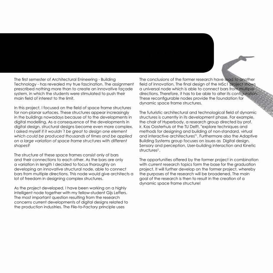
The first semester of Architectural Enineering - Building Technology - has revealed my true fascination. The assignment prescribed nothing more than to create an innovative façade system, in which the students were stimulated to push their main field of interest to the limit.
In this project, I focused on the field of space frame structures for non-planar surfaces. These structures appear increasingly in the buildings nowadays because of to the developments in digital modelling. As a consequence of the developments in digital design, structural designs become even more complex. I asked myself if it wouldn´t be great to design one element which could be produced thousands of times and be applied on a large variation of space frame structures with different shapes?
The structure of these space frames consist only of bars and their connections to each other. As the bars are only a variation in length I decided to focus thoroughly on developing an innovative structural node, able to connect bars from multiple directions. This node would give architects a lot of freedom in designing complex structures.
As the project developed, I have been working on a highly intelligent node together with my fellow-student Gijs Leffers. The most important question resulting from the research concerns current developments of digital designs related to the production industries. The File-to-Factory principle uses
The conclusions of the former research have lead to another field of innovation. The final design of the MSc1 project shows a universal node which is able to connect bars from multiple directions. Therefore, it has to be able to alter its configuration. These reconfigurable nodes provide the foundation for dynamic space frame structures.
The futuristic architectural and technological field of dynamic structures is currently in its development phase. For example, the chair of Hyperbody, a research group directed by prof. ir. Kas Oosterhuis at the TU Delft, "explore techniques and methods for designing and building of non-standard, virtual and interactive architectures"1. Furthermore also the Adaptive Building Systems group focuses on issues as Digital design, Sensory and perception, User-building interaction and Kinetic structures2 .
The opportunities offered by the former project in combination with current research topics form the base for the graduation project. It will further develop on the former project, whereby the purposes of the research will be broadened. The main goal of the research is then to result in the creation of a dynamic space frame structure!
Preface
7
Image: ONL (2006) Wireframe render of ‘The Cockpit’ (Utrecht)1. http://www.bk.tudelft.nl/live/pagina.jsp?id=022afd95-6275-4991-9060-02b2b2aefad3&lang=en (08 May 2011)2. http://www.bk.tudelft.nl/live/pagina.jsp?id=eacb5c10-640a-4001-bbcf-e0a2e38fe734&lang=nl (08 May 2011)
I would like to thank all of my tutors gratefully. Karel Vollers has from the beginning on believed the possibilities and feasibility of the research project. He was a great source of inspiration and was also important for keeping my feet on the ground when my ideas got overly ambitious. Andrew Borgart has been essential in stimulating and evaluating on the ambitious research potentials from a practical and feasible point of view. Frank Schnater has been crucial in keeping the research within the boundaries and coordinating the overall research process. I would also like to thank Michela Turrin for her enthusiastic and very helpful support from the beginning on.
I got a lot of energy and ambition out of the surprising and supporting reactions of family and friend, colleagues, other students and people who are just walking by. I would like to thank everybody who has contributed to this inexhaustible and essential source of energy.
Preface

8
1. Project description 11
2. Theory on geometry 17
3. Geometry 33
4. Dynamics 47
5. Structural elements 71
Future developments 88
Evaluation 90
List of images 92Sources 94
ONL (2006) BMW Ekris (Utrecht)
Content
9
ONL (2006) BMW Ekris (Utrecht)
Content

Foster and Partners (2004) Great Court of the British Museum (London)

1 The explanation of the ambition has showed the intention of the project. This first chapter will deal with the method which is used to research on this technological and architectural innovative field. Thereby it will also treat the project boundaries and constraint which have been stated, to prevent getting off the track while still aiming at researching within broad perspectives.
Project description
Michel Buijsen | 151 92 9823rd June 201112 Dynamic Space Frame Structure
Building Technology Graduation Project 2010-'11
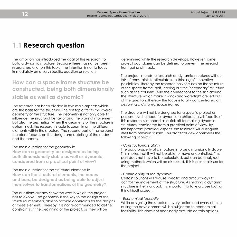
The ambition has introduced the goal of this research, to build a dynamic structure. Because there has not yet been researched a lot on this topic, the intention is not to focus immediately on a very specific question or solution.
How can a space frame structure be constructed, being both dimensionally stable as well as dynamic?The research has been divided in two main aspects which are the basis for the structure. The first topic treats the overall geometry of the structure. The geometry is not only able to influence the structural behavior and the ways of movement, but also the aesthetics. When the geometry of the structure is determined, the research is able to zoom in on the different elements within the structure. The second part of the research therefore focuses on the design and detailing of the nodes and the beams.
The main question for the geometry is:How can a geometry be designed as being both dimensionally stable as well as dynamic, considered from a practical point of view?
The main question for the structural elements is:How can the structural elements, the nodes and bars, be designed as being able to adjust themselves to transformations of the geometry?
The questions already show the way in which the project has to evolve. The geometry is the key to the design of the structural members, able to provide constraints for the designs of these elements. Thereby, it is not recommended to define constraints at the beginning of the project, as they will be
1.1 Research question
determined while the research develops. However, some project boundaries can be defined to prevent the research from going off track.
The project intends to research on dynamic structures without lots of constraints to stimulate free thinking of innovative possibilities. Thereby the research only focuses on the structure of the space frame itself, leaving out the ´secondary´ structure such as the columns. Also the connections to the skin around the structure which make it wind- and watertight are left out of the question. Thereby the focus is totally concentrated on designing a dynamic space frame.
The structure will not be designed for a specific project or purpose. As the need for dynamic architecture will feed itself, this research is intended as a kick off for making dynamic structures, considered from a practical point of view. By this important practical aspect, the research will distinguish itself from previous studies. This practical view consideres the following aspects:
- Constructional stabilityThe basic property of a structure is to be dimansionally stable. This implies that it will not be able to move uncontrolled. This part does not have to be calculated, but can be analyzed using methods which will be discussed. This is a critical issue for the project.
- Controlability of the dynamicsCertain solutions will require specific and difficult ways to control the movement of the structure. As making a dynamic structure is the final goal, it is important to take a close look on this difficult aspect.
- Economical feasibilityWhile designing the structure, every option and every choice during the development will be subjected to economical feasibility. This does not necessarily exclude certain options,

Proj
ect d
escr
iptio
n
13
Response to functional requirements
Response to changing natural conditions
Response artificial environment
User behaviour Environmental impacts
Architectural criteria
- Resizing spaces- Open / Close space
- Ventilation (wind)- Sun (solar power, passive energy reduction- Rain- Surface water
Providing shelter
Wind
Air out
Air in
- People walking by
Sun protection (summer)
SummerWinter
Fig. 1.1.1 Potential fields of application1
a. Environmental impacts (ventilation)b. Functional requirements (expanding space)c. Environmental impacts (sun inlet)d. Architectural requirements1 Source: www.adaptivebuildingsystems.com (31-01-2011)
a.
c. d.
b.
but makes sure that the final design will still be feasible. Keeping this aspect in mind, it is for example important to try to use no, or as less as possible, very expensive elements.
- Technical feasibilityThe concepts and designs have to be technical feasible. This means that they have to be able to be made using not too difficult processes, because this would only result in a more valuable structure. It is also difficult to make a prototype of complex products, which is of main importance in proving that the design of a project functions as it is designed to. The following aspects will be left out:
- Application(s)It is important to realise that the research project is intended as an exploration on the field of dynamic structures. It is therefore not directly related to an architectural project or case study. However, previous and current researches already show that there is large interest for dynamic structures. Some examplar applications are illustrated in figure 1.1.1. When the research develops, certain constraint will have to be made. Hereby the end result could be subjected to a case study model.
- Constructional calculationsAs explained, the constructional stability will be treated, because this is of basic importance. Calculations can provide even more detailed information, such as the deformation of the structure and the forces in the nodes. However, this part will not be treated but assumed from earlier realized static structures. In the case that the structure will have to take higher loads, these elements will be over-dimensioned.
- Border of the structureThe research will focus upon the structure itself and will not treat connections to for example the ground floor, a wall or columns. This would again be a very specific field to research upon once this project has resulted in a feasible concept.
- Connections to a weather- and wind proof building skinJust as the borders of the structure will not be treated, the connections to the physical skin will also be left out. The materialisation of the skin itself could already form an interesting new research project.

Michel Buijsen | 151 92 9823rd June 201114 Dynamic Space Frame Structure
Building Technology Graduation Project 2010-'11
It is important to define a clear research method, which is the line which guides the research towards the end result. This part will treat the method which was used for this research, illustrated in figures 1.2.1 and 1.2.2.
The central topic of the project focuses on dynamic structures. Because there are currently a lot of developments in this field of innovation, it is important to take a close look upon literature which already has been published. This knowledge then has to be further developed. This will be done by a method called 'research by modelling', in which making physical models is important to gain more insight in certain ideas. Thereby these models are a great tool to visualize these ideas, understand their composition and generate new ideas.
To structure the research on dynamic space frame structures, it has been divided in two main topics. The first topic treats the overall aspects of the total structure. Within this field, the structural geometry is of main importance. The geometry is able to influence the structural behavior, the ways of movement and the aesthetics.
Determining the geometry enables the research to zoom in on the different elements within the structure. Space frame structures consist of length members, for example bars or tensioned cables, and their connectors, also known as nodes or joints. The structure will contain different types of these elements. Some bars will for example have to be able to alter their length whereas others have got fixed lengths. These variations will also occur in the nodes, of which some will have to be able to connect another number of length elements and some connections will have to be fixed and others have to be dynamic.
During the research, both parts have been developed simultaneously. First they will not be confronted with several aspects and constraints to stimulate freedom in thinking of new ideas and concepts. Ideas with a high potential will be tested and confronted with some constraints which creates ´feedback´. Hereby, the different research topics will be geared to one another.
Fig. 1.2.1 Description of the Research Method
1.2 Research method
Research Multidisciplinary approach
“Comparison of the effect with the original intention.”
Structural elements
Dynamic structure
FeedbackGeometry
Structure Node
Proj
ect d
escr
iptio
n
15
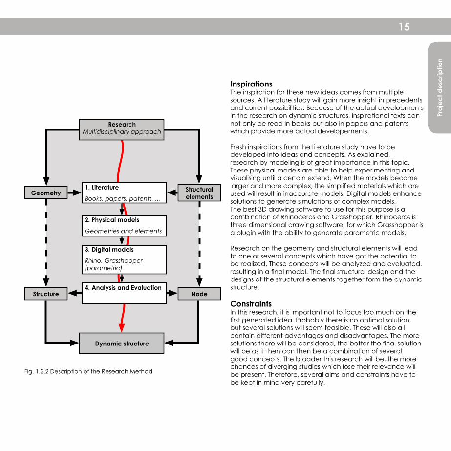
InspirationsThe inspiration for these new ideas comes from multiple sources. A literature study will gain more insight in precedents and current possibilities. Because of the actual developments in the research on dynamic structures, inspirational texts can not only be read in books but also in papers and patents which provide more actual developements.
Fresh inspirations from the literature study have to be developed into ideas and concepts. As explained, research by modeling is of great importance in this topic. These physical models are able to help experimenting and visualising until a certain extend. When the models become larger and more complex, the simplified materials which are used will result in inaccurate models. Digital models enhance solutions to generate simulations of complex models. The best 3D drawing software to use for this purpose is a combination of Rhinoceros and Grasshopper. Rhinoceros is three dimensional drawing software, for which Grasshopper is a plugin with the ability to generate parametric models.
Research on the geometry and structural elements will lead to one or several concepts which have got the potential to be realized. These concepts will be analyzed and evaluated, resulting in a final model. The final structural design and the designs of the structural elements together form the dynamic structure.
ConstraintsIn this research, it is important not to focus too much on the first generated idea. Probably there is no optimal solution, but several solutions will seem feasible. These will also all contain different advantages and disadvantages. The more solutions there will be considered, the better the final solution will be as it then can then be a combination of several good concepts. The broader this research will be, the more chances of diverging studies which lose their relevance will be present. Therefore, several aims and constraints have to be kept in mind very carefully.
Fig. 1.2.2 Description of the Research Method
Research Multidisciplinary approach
Structural elements
Dynamic structure
Geometry
NodeStructure
1. Literature
Books, papers, patents, ...
2. Physical models
Geometries and elements
3. Digital models
Rhino, Grasshopper (parametric)
4. Analysis and Evaluation
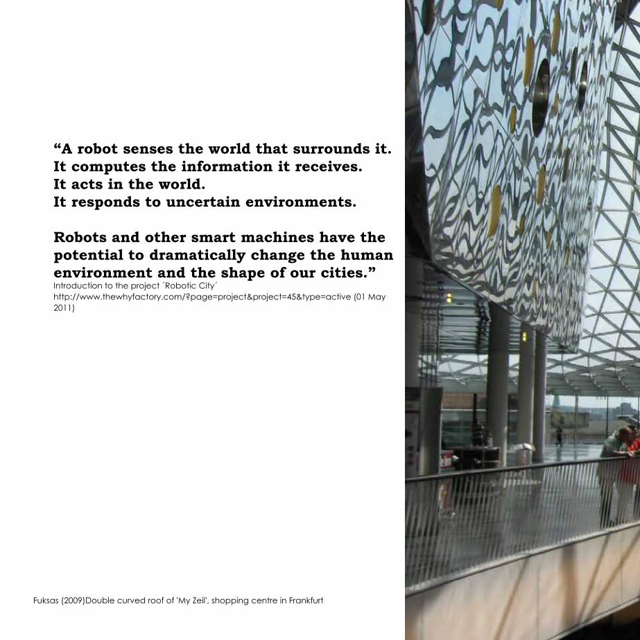
“A robot senses the world that surrounds it.It computes the information it receives.It acts in the world.It responds to uncertain environments.
Robots and other smart machines have the potential to dramatically change the human environment and the shape of our cities.”Introduction to the project ´Robotic City´ http://www.thewhyfactory.com/?page=project&project=45&type=active (01 May 2011)
Fuksas (2009)Double curved roof of 'My Zeil', shopping centre in Frankfurt
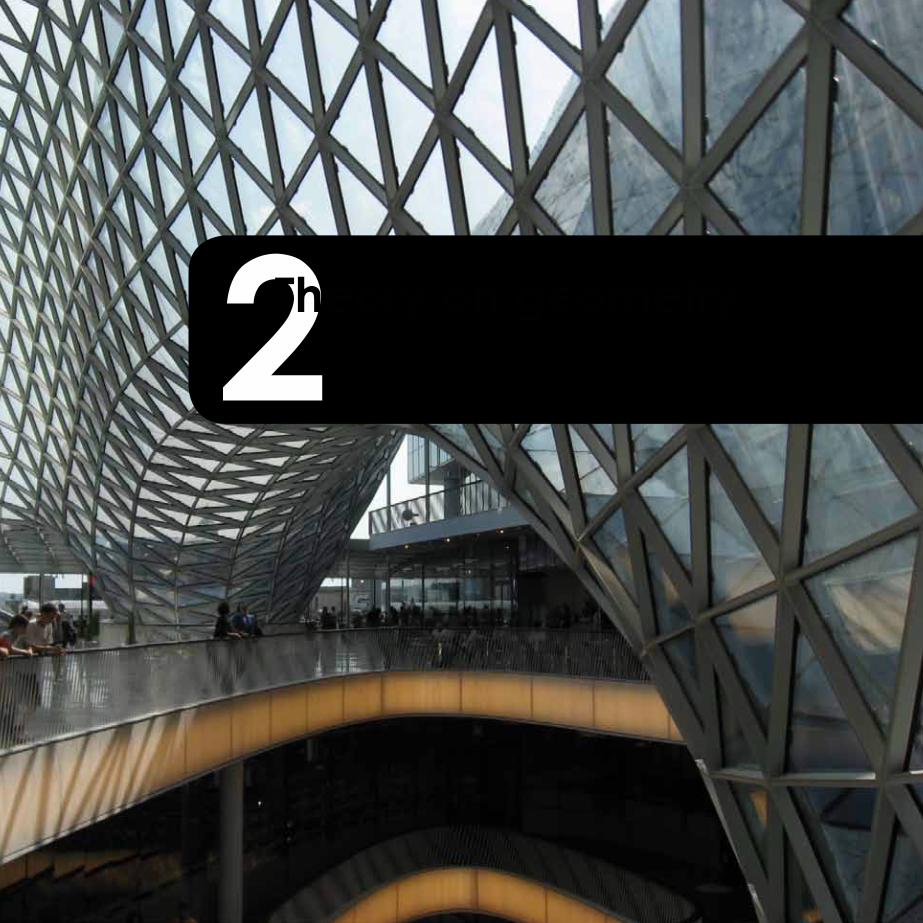
2 This first chapter will deal with the theoretical principles regarding the categorization of precedent structures and the numerical analysis on stability. This knowledge provides the basis to be able to analyse principles and concepts of the next coming chapters.
Theory on geometry

To be able to research on the geometry which is most suitable for the dynamic application, one has to understand what geometries are applied in structures and what their properties are. To begin with, a categorisation has to be developed in which the most common structures can be subsumed. A lot of research has already been done on the structural design of space structures. This has led to a variety of terms, which will first be dealed with. The coming chapters will treat precedent structural typologies. Before analysing these, terms will first be explained which will be used to distinguish and characterize the typologies.
Layers single-layer, double-/ multi-layerStructural members within or parallel to the building skin form a layer. If there is more than one layer, they will be connected by diagonal bracing members.
For structures with low out-of-plane loads, a single-layer structure is sufficient. This is mostly the case for vertical planes. A double layer structure provides much more stiffness and can take much higher out-of-plane loads. Therefore it is used for larger, horizontal spans such as roof structures. The double layer structure is the most common used multi-layer structure (structure with more than one layer). More than two layers are seldomly applied only in very specific structures.
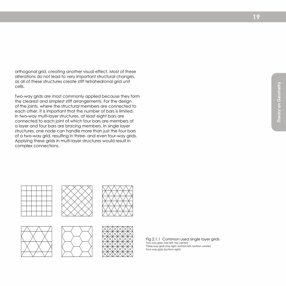
Grids two-way, three-way, four-wayThe structure is build up from a grid in which the structural elements are arranged in several directions forming triangular, quadrilateral,hexagonal or other polygonal patterns. The grids are categorized according to the number of directions in which the elements are arranged. In squared forms (quadrilateral), the elements are arranged in two directions and are therefore called two-way grids. Triangular grids consists of three directions and some specific geometries have got four directions.
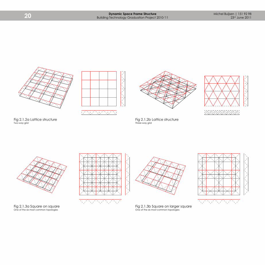
Within the categorization of multi-layer grids, there is an important distinction between space frame and lattice structures. Space frame structure - Double layer structure in which the bottom horizontal member is not set in the same vertical plane under the top horizontal member (figures 2.1.3a-f).Lattice structure - Structure in which the bottom horizontal member is set in the same vertical plane under the top horizontal member (figures 2.1.2a-b).
Some multi-layer structures show a very obvious repetition of 3D cells which are called the grid unit cells. The design of many common multi-layer structures can also be regarded as a result of connecting grids by bracing members. In those cases the typical grid unit cell cannot always be clearly distinguished.
The most common used multi-layer space frame structures are showed in figure 2.1.2 and 2.1.3. A structural analysis of these typologies reveals interesting results which can be noticed as important principles before developing on the dynamic structure.
The main striking result is that all structures are build up from two-way grids. The six geometries show a variety of possibilities in which the squared grid can be applied. Figure 2.1.3a shows the most common structure of a square-on-square typology in which the corners of the squares in the top layer are positioned above the centres of the squares bottom layer. Figure 2.1.3b shows a variation in which the bottom layer has a grid size which is twice the size of the top layer, resulting in a visual and structural lighter construction because of the empty spaces in the middle of the large squares in the bottom layer. This same principle is repeated in figures 2.1.3c-d, where the grid is not orthogonal, but diagonal. Then there is also a typology which combines the diagonal and orthogonal arrangement in respectively the top and bottom layer. In these structures, the bracing members are in line with the
Michel Buijsen | 151 92 9823rd June 201118 Dynamic Space Frame Structure
Building Technology Graduation Project 2010-'11
2.1 Common geometrical typologies
Theo
ry o
n G
eom
etry
orthogonal grid, creating another visual effect. Most of these alterations do not lead to very important structural changes, as all of these structures create stiff tetrahedronal grid unit cells.
Two-way grids are most commonly applied because they form the clearest and simplest stiff arrangements. For the design of the joints, where the structural members are connected to each other, it is important that the number of bars is limited. In two-way multi-layer structures, at least eight bars are connected to each joint of which four bars are members of a layer and four bars are bracing members. In single layer structures, one node can handle more than just the four bars of a two-way grid, resulting in three- and even four-way grids. Applying these grids in multi-layer structures would result in complex connections.
19
Fig 2.1.1 Common used single layer gridsTwo-way grids (top left, top center)Three-way grids (top right, bottom left, bottom center)Four-way grids (bottom right)
Michel Buijsen | 151 92 9823rd June 201120 Dynamic Space Frame Structure
Building Technology Graduation Project 2010-'11
Fig 2.1.3a Square on squareOne of the six most common topologies
Fig 2.1.3b Square on larger squareOne of the six most common topologies
Fig 2.1.2a Lattice structureTwo-way grid
Fig 2.1.2b Lattice structureThree-way grid

Theo
ry o
n G
eom
etry
21
Fig 2.1.3c Diagonal on larger squareOne of the six most common topologies
Fig 2.1.3e Diagonal on diagonalOne of the six most common topologies
Fig 2.1.3d Larger square on diagonalOne of the six most common topologies
Fig 2.1.3f Diagonal on squareOne of the six most common topologies
Fig 2.1.3b Square on larger squareOne of the six most common topologies

Michel Buijsen | 151 92 9823rd June 201122 Dynamic Space Frame Structure
Building Technology Graduation Project 2010-'11
For the geometry of dynamic structures it is important that the structure is able to remains standing in different configurations. The essence to achieve this lies in being dimensional stable. A structure is dimensionally stable if it does not change its configuration as a result of external forces. Hereby the joints are hinged, because otherwise the bending moments will occur in the tubular members. Different forms will be analyzed to demonstrate this principle and relate it to certain common used geometries.
A combination of vertices and lines determine the geometry of a form. The form with the least number of elements is the triangle, bounded by three vertices and three edges. Adding a vertex and an edge results in a rectangle and n more vertices and n more edges result in other polygons. Let´s first take a closer look upon the triangles.
When taking a closer look upon triangles, it can be noticed that a triangle is build up from three edges which have each got a specific length. These edges are able to only sompose one kind of triangle, which is therefore also does not have the ability to alter its form. This contradicts to rectangular forms, containing four edges with each a specific length. Unless some of the joints are stiff, the rectangle is able to alter its form resulting in lozenge-shaped forms.
2.2 Dimensional stability
Fig 2.2.1 Dimensional stability of different formsa. Triangular structureb. Quadrilateral structure (without forces on the structure)c. Quadrilateral structure (with forces)
a. b. c.
As figure 2.2.1 shows, in two dimensional structures only the triangular structure is stable. The joints and tubular members can be coded with respectively 'k' and 's'. A formula shows the relation between the number of joints and tubular members for a stable structure in the following way: Triangle For n extra trianglesJoints 'k' 3 n k = 3 + nTubular members 's' 3 2n s = 3 + 2n
To remove the value n, the formula for the tubular members is subtracted from the formula for the number of joints, which multiplied by two. This results in the formula s = 2k - 3. It is very important to notice that this formula is a necessary condition, but is not sufficient. This means that the formula has to be right, but if it is right it can still not be ensured that the structure is stable. This will be explained by the some examples, illustrated in figure 2.2.2.
Figure 2.2.2a and b show several stable triangles for which also the formula is right. In figure 2.2.2 six triangles have generated a closed hexagonal form, in which the formula is not right, but the structure still is stable. On the contrary, figure 2.2.2d illustrates a structure for which the formula is right but the structure is not stable. With only one member moved, figure Xe illustrates a stable structure. By these examples can be concluded that the formula has to be right, but it does not necessarily give a stable structure. Nor does the formula have to be right for a structure which is stable.
As the stability of a structure cannot be numerically determined, a few rules of thumb enable examining the structure. This is illustrated in figure 2.2.3.

Theo
ry o
n G
eom
etry
23
Fig 2.2.2 Check of dimensional stability by using the formulasThe red forms and red calculations show where respectively the structure is instable or the calculation is wrong
Fig 2.2.3 Check of dimensional stability by rules of thumbThe red geometry and red calculations show where respectively the structure is instable or the calculation is wronga. An instable, non-triangular form is surrounded by a stable configuration and three different stable formsb. An instable, non-triangular form is surrounded by three stable configurationsc. A stable, non-triangular form is surrounded by two stable configurationsd. A stable, non-triangular form is surrounded by one stable configuration and contains two free edgese. An instable, non-triangular form is surrounded by one stable configuration and contains three free edges
s = 2k - 3s = 5k = 4
5 = 2*4 - 35 = 5
s = 2k - 3s = 11k = 7
11 = 2*7 - 311 = 11
s = 2k - 3s = 12k = 7
12 = 2*7 - 312 = 11
s = 2k - 3s = 15k = 9
15 = 2*9 - 315 = 15
s = 2k - 3s = 15k = 9
15 = 2*9 - 315 = 15
a.
a.
b.
b.
c.
c.
d.
d.
e.
e.
1. Check the structure on (stable) trianglesThese forms are stable2. Check if at least one edge of the triangles is connected to another stable formThis configuration of forms is stable3. Check if the other (non-stable) forms are connected to at least n edges by maximal two stable configurations. The number (n) of edges is determined by the number of edges minus two. This structure is stable

Michel Buijsen | 151 92 9823rd June 201124 Dynamic Space Frame Structure
Building Technology Graduation Project 2010-'11
Polygons and polyhedra have a lot of properties in common. The polygonal properties explain how regular polygons are composed. In the same logic, polyhedra can also be classified as being regular and semi-regular. The regular types contain edges of equal length and equal angles, whereas semi-regular types are composed of a variety of regular types. The difference can also be explained in the following way:
"Regular polyhedra have only one kind of 'dihedral' angle (angle between two faces) and 'Vertex figure' (figure obtained by joining the mid points of edges around a vertex). Semi regular polyhedra have more than one kind of dihedral angle and the vertex figure is a non-regular polygon."[Narayanan, 2006, p.779]
There are five types of regular polyhedra, which are known as Platonic solids, discovered by Plato (see figure 2.3.3). There are also fourteen types of irregular polyhedra, of which thirteen are known as the Archimedis solids, discovered by Archimedis (see figure 2.3.4). The fourteenth has been discovered by Ashkinuz. For this case, mainly the regular polyhedra are important because of their properties to be repetitive in terms of edge lengths and face figures. The definitions of the polygons and polyhedra are both derived from the number of edges.
The report has to deal with a lot of specific terms. Some of these are general and others are user-interpreted. In this section, the relevant terminology for the geometrical study will be explained.
Geometrical elementsPolygon Planar 2 dimensional face (F), bounded by a closed path composed of straight line segments (E) running through vertices (V)Polyhedron "Many faced 3 dimensional [shape], composed of points, lines and planes, generally referred to as vertices (V), faces (F) and edges (E) respectively." [Narayanan, 2006, p.779]
Vertex (V) Point elementEdge (E) Straight line elementFace (F) Planar 2 dimensional surface
Polygonal propertiesCyclic Polygon in which all vertices lie on a single circleEquilateral Polygon in which all sides are of equal lengthRegular Polygon which is both equilateral and cyclic
Polygonal and polyhedronal propertiesConvex Form in which one of the interior angles (angle of two edges measured in a vertex) is more than 180 degrees (figure 2.3.2a)Concave Form in which all interior angles are less than 180 degrees (figure 2.3.2b)
Compositions of geometrical elementsGrid 2 Dimensional network of lines which are parallel to each other positioned under equal distances in multiple directionsPattern Repetition of forms (2D) or shapes (3D)
2.3 Geometry Polygons, Polyhedra and Solids

Theo
ry o
n G
eom
etry
25
Fig 2.3.2 Convex (a) and concave (b) polygonsWhether or not a polygon is concave can be checked by drawing a line which runs through a vertex. When this line touches the polygon twice, the polygon is concave (b)
Fig 2.3.1 Random structureContaining vertices (V), edges (E) and faces (F)
a.
V E
F
b.
Fig 2.3.3 Five Platonic solids and their netsa. Tetrahedronb. Cubec. Octahedrond. Dodecahedrone. Icosahedron
a.
b.
c.
d.
e.

Michel Buijsen | 151 92 9823rd June 201126 Dynamic Space Frame Structure
Building Technology Graduation Project 2010-'11
The surfaces which are relevant for this study, can be divided in two categories. The first cateogory is that of the developable surfaces, the second one treats freeform surfaces.
Developable surfacesDevelopable surfaces are characterized by the property that they can be mapped isometrically into the plane [Pottmann, 2007]
Surfaces which are developable can be folded from a planar surface. Three basic types of developable surfaces are cylinders, cones and tangent surfaces of space curves, illustrated in figure 2.4.1. Cylinders are formed by 'a family of parallel lines' [Pottmann, 2007]. Cones consists of lines which connect the central vertex point with points at the base (figure 2.4.2). Concerning the central points for the rotation, the three types of developable surface have other properties. The cylinder has got one center vertex, which is extruded parallel to the extrusion of the base curve creating a straight central axis. None of the lines of the cylinder touch the central axis. The cones also have one vertex which is joined by all the lines. The tangent surface is a combination of multiple central vertices which are spread over a space line. Regarding the outfolds of the curved surfaces, notice that the cylinders and the cones consist of equal segments and the tangent surfaces of a space curve are all unique segments.
Developable surfaces have the ability to only generate very limited transformations. Basic geometries for the structure will consists of one or two types of cells, resulting in the ability to create cylindrical or conical curved surfaces out of a planar surface. If more complex transformations have to be achieved, the cells will have to be able to alter their edges resulting in for example trapezoids from squares.
Freeform surfacesFreeform surfaces can be categorized in bézier surface and B-Spline and NURBS surfaces (figures 2.4.3). Bézier surfaces are named after the bézier curves, from which the surfaces are build up. The B-Spline and NURBS surfaces are constructed from control points instead of curves. These surfaces can be constructed in an open or closed mode. As the various applications for the dynamic structure focus on the skin of a building, the closed mode will not yet be relevant.
The developable surfaces have shown three types, of which the cylinder and the cone are curved in one direction, also called single curved. Double curved surfaces belong to the category of freeform surfaces. Making freeform surfaces dynamic is very hard, because each cell has got a different shape. This can be demonstrated by dividing a sphere into segments. However the earth is a closed shape, its division into degrees of latitude and degrees of longitude is a very clear example. In the most common division, one can see that the segments are more narrow towards the top. An attempt to divide the earth into equal pieces has resulted in the grid structure which is illustrated in figure 2.4.4.
So, it is possible to create a sphere out of equal segements. However, outfolding this sphere will result in a non-regular grid, as has already been discussed and illustrated in figure 2.4.4. Therefore, these shapes cannot be transformed into planar surfaces. An investigation on possible deformations for developable and freeform surfaces will follow in the next chapter, resulting in constraints for the structure and its geometry and nodular system.
2.4 Geometry Surfaces

Theo
ry o
n G
eom
etry
27
Fig 2.4.1 Developable surfacesa. Cylinderb. Conec. Tangent surface of a space curve
Fig 2.4.2 Unfolding a cone
b. c.a.
Fig 2.4.4 Unfolding a geodesic sphereFig 2.4.3 Bézier (a) and B-Spline surfaces (b)
a. b.
2.4 Geometry Surfaces

Michel Buijsen | 151 92 9823rd June 201128 Dynamic Space Frame Structure
Building Technology Graduation Project 2010-'11
2.5 Geometry Transformations
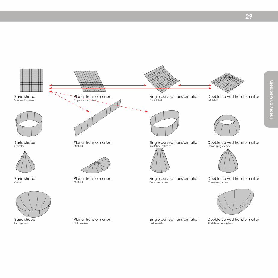
After having explained the differences and properties between developable surfaces and freeform surfaces, the time has come to start making first constraints. In this chapter, different basic shapes will be subjected to different transformations (figure 2.5.1). After analysing the possibilities it will be determined which structure will be chosen to develop further.
PlaneUsing the plane as a starting point gives a lot of opportunities for transformations. The first one is an in-plane transformation, leading to for example a trapezoidal structure. Thereby it can also be easily rotated in one direction, resulting in a curved surface. As the previous chapter has explained, it is hard to create double curvature from a plane. An interesting possibility for creating double curvature for a planar surface is making the cells of the grid actuated, whereby it can lead to local curvature.
CylinderAs well as the plane, he cylinder is also able to transform into interesting shapes. Unfolding the cylinder results in a plane, which can be the same as the plane as just has been discussed. Other transformations of the cylindrical shape are stretching the cylinder (single curved) or offsetting the curved line, whereby creating double curvature.
ConeA cone is a developable surface, which means that it can be unfolded to a planar surface. For basic cones, this surface contains a central vertex (top of the cone) around which radial lengths are rotated. To be able to unfold the cones, one edge has to be splitted. The angle between both edge
Fig. 2.5.1 (right page) Transformation of basic shapes into planar, single- and double curved shapesThe red lines indicate interesting relationsThe red dotted lines indicate interesting relations between different basic shapesBasic shapes (left column): Planar square, Cylinder, Cone and Hemisphere
in the plane depends on the radius of the base of the cone. It generates a specific shape and is thereby not universally applicable. The single- and double curvatures show interesting aspects, but do not very much transform the shape of the cone. Another important aspect for the cones is that they are not very commonly used shapes in architecture. This makes the cone not very interesting to specifically research upon.
HemisphereThe hemisphere is a freeform surface. As the previous chapter has shown, it is possible to construct a (hemi-)sphere out of one type of triangle. It is however not feasible to totally unfold the shape, because that would result in a surface containing open and closed parts. A solution for this is to only slightly deform the sphere, whereby the triangles are able to alter the length of their edges. This could lead to a stretched shape which is illustrated at the double curved transformation.
ConclusionBoth the plane and the cylinder have got lots of opportunities for being transformed into planar, single- and double curved surfaces. As outfolding the cylinder results in a plane and, inversely, curving a plane results in a cylinder they are both based on the same starting point.
The research will continue researching on transformations of planar surfaces into a single curved surface (the 'partial shell' and a double curved surface (the 'molehill').
Theo
ry o
n G
eom
etry
29
Basic shapeSquare, top view
Planar transformationTrapezoid, top view
Single curved transformationPartial shell
Double curved transformation´Molehill´
Basic shapeCylinder
Basic shapeCone
Basic shapeHemisphere
Planar transformationOutfold
Planar transformationOutfold
Planar transformationNot feasible
Single curved transformationStretched cylinder
Single curved transformationTruncated cone
Single curved transformationNot feasible
Double curved transformationConverging cylinder
Double curved transformationConverging cone
Double curved transformationStretched hemisphere
2.5 Geometry Transformations
Michel Buijsen | 151 92 9823rd June 201130 Dynamic Space Frame Structure
Building Technology Graduation Project 2010-'11
2.6 Force distribution in double layered space frames
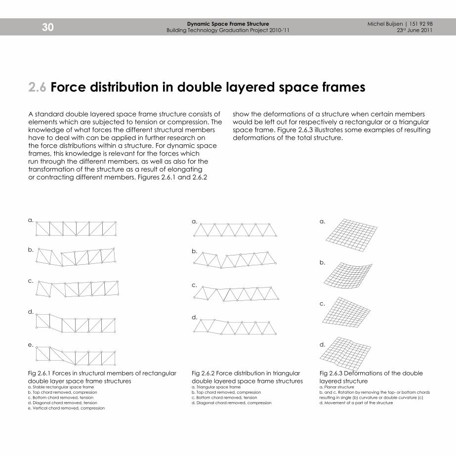
A standard double layered space frame structure consists of elements which are subjected to tension or compression. The knowledge of what forces the different structural members have to deal with can be applied in further research on the force distributions within a structure. For dynamic space frames, this knowledge is relevant for the forces which run through the different members, as well as also for the transformation of the structure as a result of elongating or contracting different members. Figures 2.6.1 and 2.6.2
Fig 2.6.1 Forces in structural members of rectangular double layer space frame structuresa. Stable rectangular space frameb. Top chord removed, compressionc. Bottom chord removed, tensiond. Diagonal chord removed, tensione. Vertical chord removed, compression
Fig 2.6.2 Force distribution in triangular double layered space frame structuresa. Triangular space frameb. Top chord removed, compressionc. Bottom chord removed, tensiond. Diagonal chord removed, compression
Fig 2.6.3 Deformations of the double layered structurea. Planar structureb. and c. Rotation by removing the top- or bottom chords resulting in single (b) curvature or double curvature (c)d. Movement of a part of the structure
a. a. a.
b. b.
b.
c.c.
c.d.
d.
d.e.
show the deformations of a structure when certain members would be left out for respectively a rectangular or a triangular space frame. Figure 2.6.3 illustrates some examples of resulting deformations of the total structure.

Theo
ry o
n G
eom
etry
31
2.7 Conclusion
At the beginning of this research project, there was no field of application and thereby also no constraints. This first chapter has guided the research through a few steps to the determination on the basic form and the possible transformation of a surface. Surfaces can be divided into two categories; developable and freeform surfaces. The developable surfaces can be folded from a single piece of paper, and are thereby single curved. Freeform surfaces contain rotation in more than one direction. Because the research tends not to focus very specifically on one or a few basic shapes and transformations, it is most likely to make the structure able to handle double curvature, whereby it would also have the ability to transform in a single plane. This seemed however not the case. As spheres cannot be unfolded, making a (hemi-)sphere planar is not possible. Further developments in the research will take a planar surface as a basic shape which will have to be single curved and double curved like the 'molehill' surface illustrates (figure 2.7.1).
This chapter has furthermore focused on the theoretical background which is essential to understand and be able to design structures in the coming chapters. These parts therefore do not have specific conclusions yet, but will come forward in the further development.
Fig 2.7.1 Concepts for transformationa. Basic shapeb. Concept 1 - Single curvaturec. Concept 2 - Double curvature
a. b.
c.
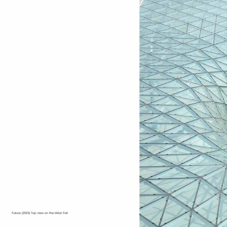
Fuksas (2005) Top view on the Milan Fair

3 The first research topic is about the geometry of the structure. Several geometries have been developed and analyzed to lead to a final geometry, which can be investigated on its behavior in static and dynamic cases. The development of these models and their conclusions are explained in the first section.
Geometry

Michel Buijsen | 151 92 9823rd June 201134 Dynamic Space Frame Structure
Building Technology Graduation Project 2010-'11
View on the Kagome Plate Truss Structure
Kagome Plate Truss Structure
Cell Top view Side view
Front view
Perspective view
At the start of the development of the geometry, it was very hard to think of a geometry which could be feasible for the dynamic structure. The structure has to provide a solution for various challenges, like having the ability to move as well as being dimensional stability. To start with, a precedent research project has been analysed. The project used for the precedent analysis has been published in a paper called
‘Kagome plate structures for actuation’ [R.G. Hutchinson, N.A. Fleck et al, 2003]. This paper claimed to have identified a “truss structure based on the ancient Kagome basket weave pattern with exceptional characteristics for actuation”. To be able to analyze the model, it has been built to visualize for example how the structure is constructed and what transformations it can handle.
3.1 Geometry Precedent analysis: Kagome Plate Truss Structure

Geo
met
ry
35
Neutral position of the bottom layer
View on the Kagome Plate Truss StructureOne corner of a tetrahedron lifted,
causing a slight deformation in the structure
3.1 Geometry Precedent analysis: Kagome Plate Truss Structure

Michel Buijsen | 151 92 9823rd June 201136 Dynamic Space Frame Structure
Building Technology Graduation Project 2010-'11
The goal for the research on the Kagome Plate Truss Structure was to "achieve arbitrary in-plane nodal displacements with minimal internal resistance [and] having both isotropic stiffness and the properties desired for actuation". Because of the in-plane transformation, the application wherefore the Kagome Structure is designed differs from dynamic structures this research is about. However, this actuated structure shows very intelligent and interesting features, which can lead to basic design principles for dynamic structures.
The most striking and crucial elements of this Truss Structure are the tetrahedrons. The arrangement of these shapes around a hexagonal shape provides a structure which is applicable in form-active structures. The paper deals with two structures; one being a single Kagome layer with tetrahedrons and the other being a double Kagome layer, both provided with tetrahedrons connected to each other at the tops. The physical model (figures X) shows that the dynamics in the single and double layer structures differ very much.
For analyzing the possible movements in the Kagome Structure, the following principles illustrate both the single and double layer structures in 2D. In the principles it is clear to see that the single layer structure provides more freedom in out-of-plane deformation with less actuated members. Therefore the application of this section is further explored in following geometries.
Another important aspect for the analysis of the Kagome Plate Truss Structure is the total geometry of the structure. Because the single and double layer Kagome Structures are horizontally mirrored, there is no difference as seen from the top. The illustration op page 34 shows a more detailed view including the side and front views. The extraction of figure 3.1.2 shows the hexagonal space in between of the triangular - tetrahedronal - units. An important advantage of this arrangement is that the structure is isotropic, meaning that it provides equal strength in all directions. A disadvantage of hexagonal shapes is that they are not static determined. By connecting all sides to triangles, which are also connected to other hexagonals a network is created which is not stiff and thereby has the perfect ability to deform in-plane but nog out-of-plane.
It is very interesting to see in figure 3.1.2a is the intelligent composition of different cell types which are used for different purposes. The stiff triangular cells (grey) provide stiffness, whereas the hexagonal cells provide flexibility in horizontal movement.
Fig 3.1.1 Principle of Kagome Structuresa. double layer Kagome gridb. single layer Kagome grid
Fig 3.1.2 Top views on neutral and deformed structuresa. top view on Kagome Structure, showing the isotropic propertiesb. top view on an in-plane deformation
a.
a.
b.
b.
Geo
met
ry
37
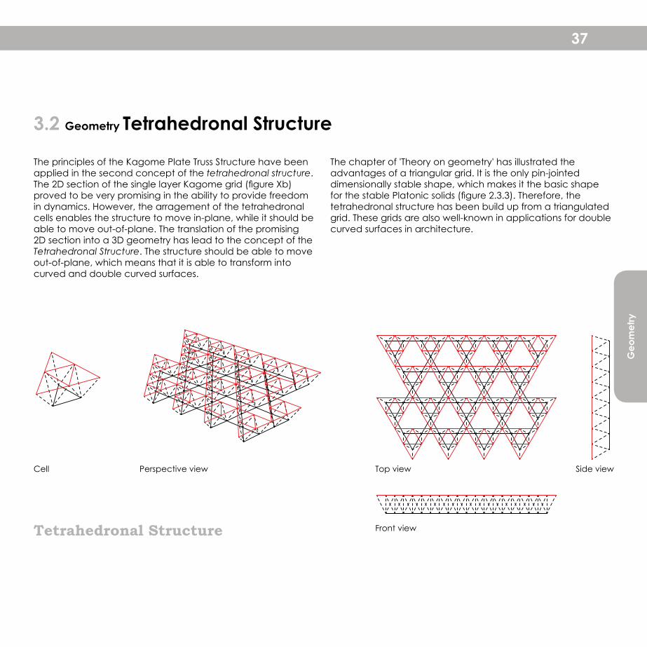
Tetrahedronal Structure
3.2 Geometry Tetrahedronal Structure
Cell Top view Side view
Front view
Perspective view
The principles of the Kagome Plate Truss Structure have been applied in the second concept of the tetrahedronal structure. The 2D section of the single layer Kagome grid (figure Xb) proved to be very promising in the ability to provide freedom in dynamics. However, the arragement of the tetrahedronal cells enables the structure to move in-plane, while it should be able to move out-of-plane. The translation of the promising 2D section into a 3D geometry has lead to the concept of the Tetrahedronal Structure. The structure should be able to move out-of-plane, which means that it is able to transform into curved and double curved surfaces.
The chapter of 'Theory on geometry' has illustrated the advantages of a triangular grid. It is the only pin-jointed dimensionally stable shape, which makes it the basic shape for the stable Platonic solids (figure 2.3.3). Therefore, the tetrahedronal structure has been build up from a triangulated grid. These grids are also well-known in applications for double curved surfaces in architecture.
Fig 3.1.2 Top views on neutral and deformed structuresa. top view on Kagome Structure, showing the isotropic propertiesb. top view on an in-plane deformation
Michel Buijsen | 151 92 9823rd June 201138 Dynamic Space Frame Structure
Building Technology Graduation Project 2010-'11
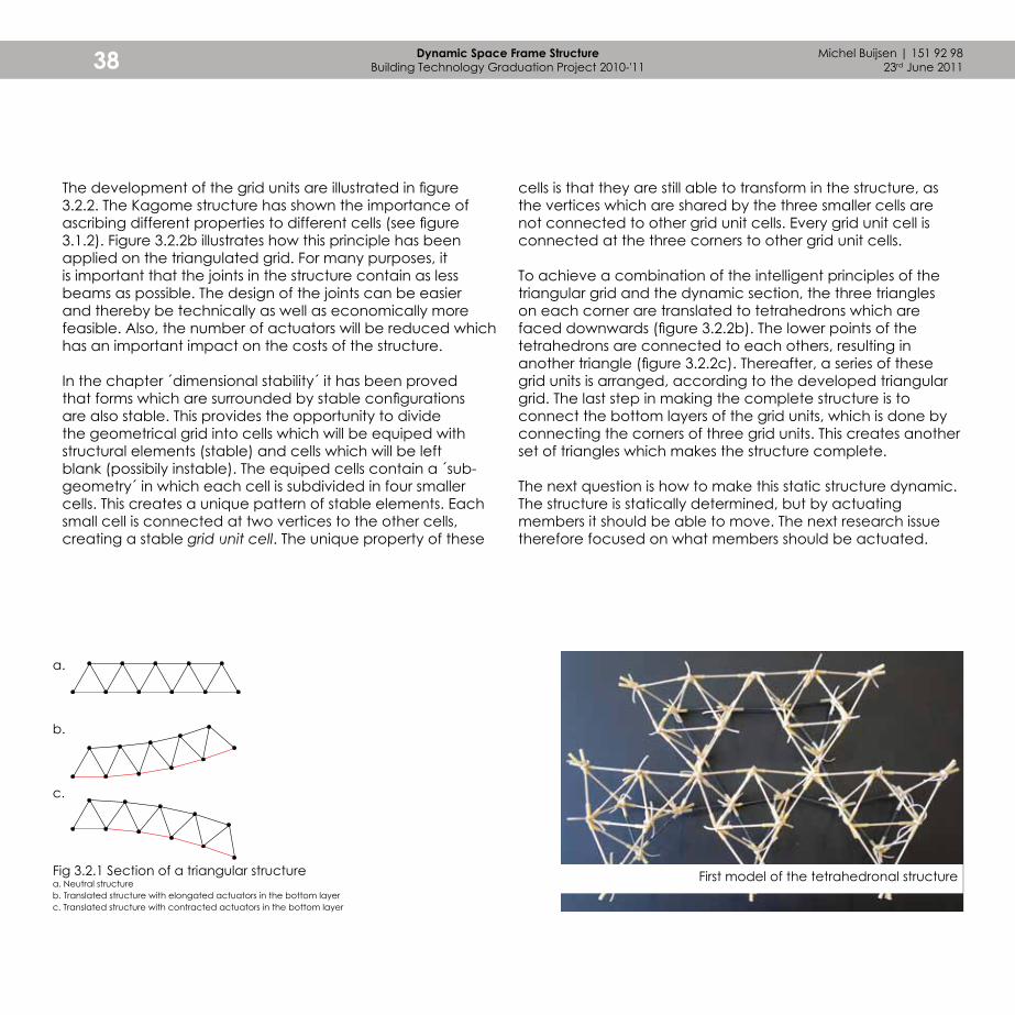
The development of the grid units are illustrated in figure 3.2.2. The Kagome structure has shown the importance of ascribing different properties to different cells (see figure 3.1.2). Figure 3.2.2b illustrates how this principle has been applied on the triangulated grid. For many purposes, it is important that the joints in the structure contain as less beams as possible. The design of the joints can be easier and thereby be technically as well as economically more feasible. Also, the number of actuators will be reduced which has an important impact on the costs of the structure.
In the chapter ´dimensional stability´ it has been proved that forms which are surrounded by stable configurations are also stable. This provides the opportunity to divide the geometrical grid into cells which will be equiped with structural elements (stable) and cells which will be left blank (possibily instable). The equiped cells contain a ´sub-geometry´ in which each cell is subdivided in four smaller cells. This creates a unique pattern of stable elements. Each small cell is connected at two vertices to the other cells, creating a stable grid unit cell. The unique property of these
cells is that they are still able to transform in the structure, as the vertices which are shared by the three smaller cells are not connected to other grid unit cells. Every grid unit cell is connected at the three corners to other grid unit cells.
To achieve a combination of the intelligent principles of the triangular grid and the dynamic section, the three triangles on each corner are translated to tetrahedrons which are faced downwards (figure 3.2.2b). The lower points of the tetrahedrons are connected to each others, resulting in another triangle (figure 3.2.2c). Thereafter, a series of these grid units is arranged, according to the developed triangular grid. The last step in making the complete structure is to connect the bottom layers of the grid units, which is done by connecting the corners of three grid units. This creates another set of triangles which makes the structure complete.
The next question is how to make this static structure dynamic. The structure is statically determined, but by actuating members it should be able to move. The next research issue therefore focused on what members should be actuated.
First model of the tetrahedronal structureFig 3.2.1 Section of a triangular structurea. Neutral structureb. Translated structure with elongated actuators in the bottom layerc. Translated structure with contracted actuators in the bottom layer
a.
b.
c.

Geo
met
ry
Fig 3.2.2 Development of the structure (view on geometry)a. 2D structure, triangular grid (colored cells will be subdivided)b. 2D structure, cells equipped with structural elementsc. 3D structure, triangular cells replaced by tetrahedronsd. 3D structure, structural members in the bottom layer (indicated in red) connect tetrahedrons
a. b.
c. d.
39
Before the research on the geometry focused on further development of this tetrahedronal structure, several attempts have been done to further improve the model. This has resulted in two variations, which will be dealt with in the next pages.
Michel Buijsen | 151 92 9823rd June 201140 Dynamic Space Frame Structure
Building Technology Graduation Project 2010-'11
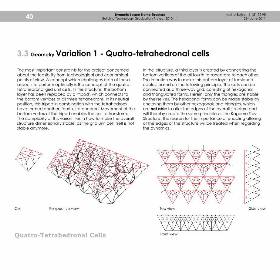
Quatro-Tetrahedronal Cells
Cell Top view Side view
Front view
Perspective view
3.3 Geometry Variation 1 - Quatro-tetrahedronal cells
The most important constraints for the project concerned about the feasibility from technological and economical points of view. A concept which challenges both of these aspects to perform optimally is the concept of the quatro-tetrahedronal grid unit cells. In this structure, the bottom layer has been replaced by a 'tripod', which connects to the bottom vertices of all three tetrahedrons. In its neutral position, this tripod in combination with the tetrahedrons have formed another, fourth, tetrahedron. Movement of the bottom vertex of the tripod enables the cell to transform. The complexity of this variant lies in how to make the overall structure dimensionally stable, as the grid unit cell itself is not stable anymore.
In the structure, a third layer is created by connecting the bottom vertices of the all fourth tetrahedrons to each other. The intention was to make this bottom layer of tensioned cables, based on the following principle. The cells can be connected as a three-way grid, consisting of hexagonal and triangulated forms. Herein, only the triangles are stable by theirselves. The hexagonal forms can be made stable by enclosing them by other hexagonals and triangles, which are not able to alter the edges of the overall structure and will thereby create the same principle as the Kagome Truss Structure. The reason for the importance of enabling altering of the edges of the structure will be treated when regarding the dynamics.

Geo
met
ry
41
Movement of the grid unit cell
Large model experimenting with the connections between the cells in the bottom layer
3.3 Geometry Variation 1 - Quatro-tetrahedronal cells

Michel Buijsen | 151 92 9823rd June 201142 Dynamic Space Frame Structure
Building Technology Graduation Project 2010-'11
Tensioned balanced cells
Cell Top view Side view
Front view
Perspective view
3.4 Geometry Variation 2 - Tensioned balanced cells
A second variation is based on the same focus to reduce the number of actuated members, stimulating the feasibility. The concept is again based on the tetrahedronal cells, this time rotated 45° around the edges which are formed by the vertices which are connected to two tetrahedrons in the top layer. The tops which now are at the corners of the triangular grid unit cell can be connected in both the bottom as the top layer. The very interesting and important property of these layers is that they form a sort of equilibrium. If the members in the top layer extend, the members in the bottom layer have to contract and vice versa. The magic trick in this concept is to make the members in the top- and bottom layer tensioned. Cables can be used, which are able to deal with these tensional forces. This enables the possibility to connect the layers by making a continuous
cable from the bottom layer through a bracing member to the top layer and back. Because the layers are inversely related to each other, this results in a grid unit cell which is in equilibrium and can be transformed by shifting cable lengths to the top- or bottom layer. In the model (right page), this movement is be caused by a single controller in the bracing member.
The models show one large disadvantage. After rotating the tetrahedrons over 45°, the structure fails as there is no equilibrium anymore. After rotating over 45° (flat structure) the distance between the vertices in the top and bottom layer do not counterbalance anymore. This is very important knowledge to apply when calculating the maximal transformation the structure is able to handle.

Geo
met
ry
43
Larger model showing failure after rotating the tetrahedrons over a certain point
Larger model experimenting with the connections and movement mechanism
Both variations do not seem to be more feasible than the basic concept. Therefore, further investigation will focus on this tetrahedronal structure.
Movement of the grid unit cell (1)
Movement of the grid unit cell (2)
3.4 Geometry Variation 2 - Tensioned balanced cells
Michel Buijsen | 151 92 9823rd June 201144 Dynamic Space Frame Structure
Building Technology Graduation Project 2010-'11
3.5 Stability Dimensional stability of the Tetrahedronal structure
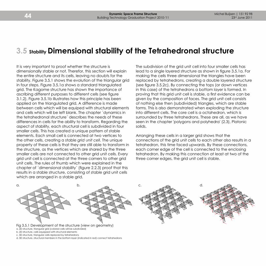
It is very important to proof whether the structure is dimensionally stable or not. Therefor, this section will explain the entire structure and its cells, leaving no doubts for the stability. Figure 3.5.1 shows the evolution of the triangular grid in four steps. Figure 3.5.1a shows a standard triangulated grid. The Kagome structure has shown the importance of ascribing different purposes to different cells (see figure 3.1.2). Figure 3.5.1b illustrates how this principle has been applied on the triangulated grid. A difference is made between cells which will be equiped with structural elements and cells which will be left blank. The chapter ´dynamics in the tetrahedronal structure´ describes the needs of these differences in cells for the ability to transform. Regarding the aspect of stability, each structural cell is subdivided in four smaller cells. This has created a unique pattern of stable elements. Each small cell is connected at two vertices to the other cells, creating a stable grid unit cell. The unique property of these cells is that they are still able to transform in the structure, as the vertices which are shared by the three smaller cells are not connected to other grid unit cells. Every grid unit cell is connected at the three corners to other grid unit cells. The rules of thumb which were explained in the chapter of ´dimensional stability´ (figure 2.2.3) proof that this results in a stable structure, consisting of stable grid unit cells which are arranged in a stable grid.
Fig 3.5.1 Development of the structure (view on geometry)a. 2D structure, triangular grid (colored cells will be subdivided)b. 2D structure, cells equipped with structural elementsc. 3D structure, triangular cells replaced by tetrahedronsd. 3D structure, structural members in the bottom layer (indicated in red) connect tetrahedrons
a. b. c. d.
The subdivision of the grid unit cell into four smaller cells has lead to a single layered structure as shown in figure 3.5.1a. For making the cells three dimensional the triangles have been replaced by tetrahedrons, creating a double layered structure (see figure 3.5.2c). By connecting the tops (or down vertices in this case) of the tetrahedrons a bottom layer is formed. In proving that this grid unit cell is stable, a first evidence can be given by the composition of faces. The grid unit cell consists of nothing else then (subdivided) triangles, which are stable forms. This is also demonstrated when exploding the structure into different cells. The core cell is a octahedron, which is surrounded by three tetrahedrons. These are all, as we have seen in the chapter 'polygons and polyhedra' (2.3), Platonic solids.
Arranging these cells in a larger grid shows that the connections of the grid unit cells to each other also results in a tetrahedron, this time faced upwards. By these connections, each corner edge of the cell is connected to the enclosing tetrahedron. By making this connection at least at two of the three corner edges, the grid unit cell is stable.

Geo
met
ry
45
Fig 3.5.2 Development of the structurea. 2D subdivided grid unit cellb. 3D grid unit cell with tetrahedronsc. 3D grid unit cell with structural members in the bottom layerd. Exploded view of a grid unit cell (grey) surrounded by other grid unit cells
a.
d.
b. c.
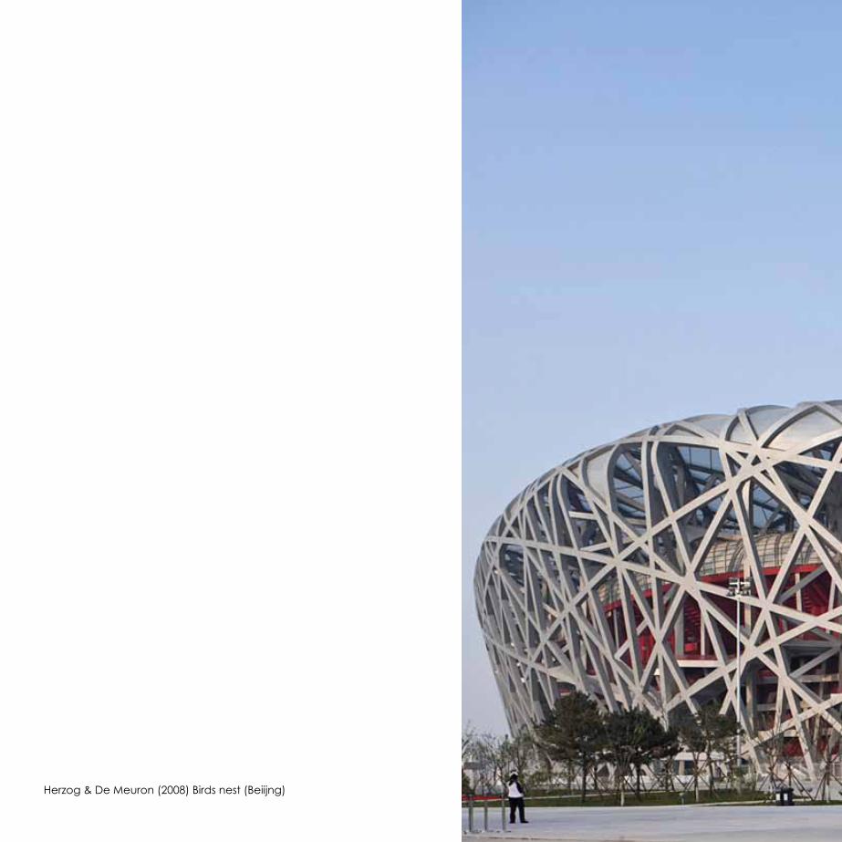
Herzog & De Meuron (2008) Birds nest (Beiijng)
4 After having determined the geometry of the structure, the investigation of dynamic structures focuses on the movement within the structure. Using the aspect of feasibility as a key issue, this chapter researches on the transformation of the structure for both of the dynamic concepts and their resulting length and angular alterations of the structural members.
Dynamics

Michel Buijsen | 151 92 9823rd June 201148 Dynamic Space Frame Structure
Building Technology Graduation Project 2010-'11
4.1 Actuation
Bottom layer actuation
As the tetrahedronal structure seems to have the best properties for being applied in dynamic structures, further investigation focuses on the actuation of this structure. It is important to notice that this first analysis is based on the actuation of a single grid unit cell. The consequences of transforming these cells for the total structure will become clear later on in the investigation.
The actuated structural members are being called the ´actuators´ and have got the properties to be able to resist tensional and compressional forces. The tetrahedronal structure consists of different groups of structural members of which the effects of being actuated will be investigated. Thereby the following groups will be investigated:- Bottom layer elements- Top layer elements- Bracing elements at the corners- Bracing elements around the core
Bottom layer actuationBecause of the development of the grid towards the final geometry, the first thought was to actuate the bottom layer and thereby rotate the tetrahedronal cells around one another. They are able to rotate over the edge which is created from the vertices they share with the other tetrahedrons. By elongating the bottom layer members, the structure will become convex and by contracting the members it will become concave. The advantage of this concept is its clear curvature which the model shows. It certainly has potential to be applied and will therefore be analyzed more deeply on the effects of actuation in the chapter 'dynamics'.
Rigid body of the grid unit cell

Dyna
mic
s
49
First model of the tetrahedronal structure
Second model including actuated elements in the bottom layer
Detailed view of the second model with bottom layer actuation
4.1 Actuation
Michel Buijsen | 151 92 9823rd June 201150 Dynamic Space Frame Structure
Building Technology Graduation Project 2010-'11
Actuation in bracing members in the core
Actuation in bracing members at the corners
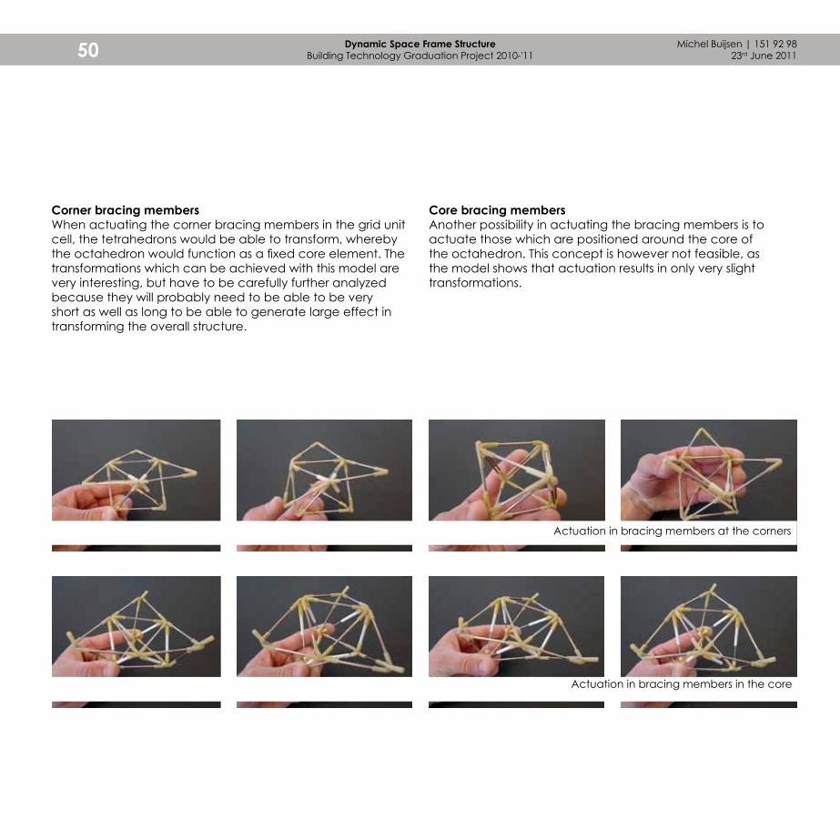
Corner bracing membersWhen actuating the corner bracing members in the grid unit cell, the tetrahedrons would be able to transform, whereby the octahedron would function as a fixed core element. The transformations which can be achieved with this model are very interesting, but have to be carefully further analyzed because they will probably need to be able to be very short as well as long to be able to generate large effect in transforming the overall structure.
Core bracing membersAnother possibility in actuating the bracing members is to actuate those which are positioned around the core of the octahedron. This concept is however not feasible, as the model shows that actuation results in only very slight transformations.

Dyna
mic
s
51
Actuation in added top layer
Top layer actuationWhen analyzing the dynamics of the bottom layer actuated structure, an important problem was identified. When actuating the bottom layer, the members had to be able to contract to a short element, whereas it also had to be able to be elongated to a long element. If these members have to be more than twice as long as they would have to be short, the members have to be telescopic resulting in more complex elements. This has a high impact on the technical as well as economical feasibility. These aspects have lead to the first top layer actuated structure concept. It can be seen that when rotating the tetrahedrons over their rotation axis, the bottom layer has to deal with large length variations, whereas the top layer only has to treat a short length alteration. In this first top layer actuated concept, the structure consists of stable tetrahedrons which are connected to actuators at their corners. This was a very interesting idea, but has a lot of structural problems because the actuators are in almost the same plane as the top layer. Thereby the actuators would have to deal with extremely high forces to contract or elongate. The second top layer actuated structure, which has been developed later on in the process, actuates the top members of the tetrahedrons.
Michel Buijsen | 151 92 9823rd June 201152 Dynamic Space Frame Structure
Building Technology Graduation Project 2010-'11
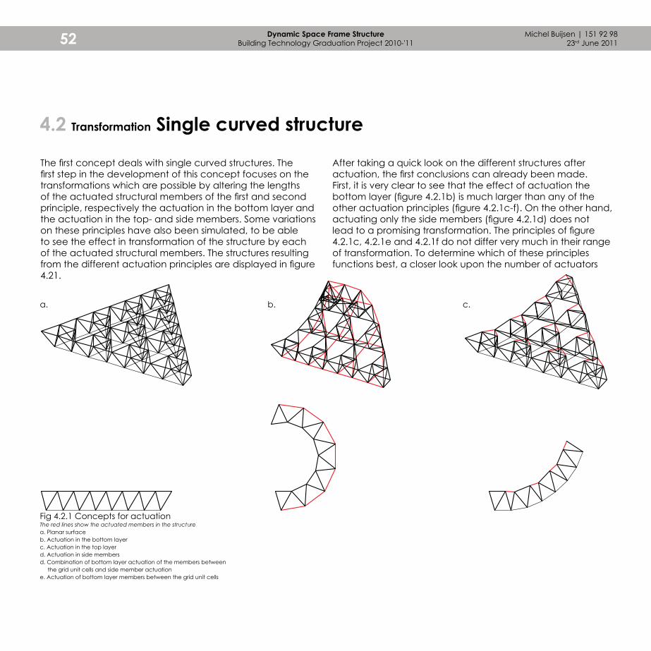
4.2 Transformation Single curved structure
The first concept deals with single curved structures. The first step in the development of this concept focuses on the transformations which are possible by altering the lengths of the actuated structural members of the first and second principle, respectively the actuation in the bottom layer and the actuation in the top- and side members. Some variations on these principles have also been simulated, to be able to see the effect in transformation of the structure by each of the actuated structural members. The structures resulting from the different actuation principles are displayed in figure 4.21.
After taking a quick look on the different structures after actuation, the first conclusions can already been made. First, it is very clear to see that the effect of actuation the bottom layer (figure 4.2.1b) is much larger than any of the other actuation principles (figure 4.2.1c-f). On the other hand, actuating only the side members (figure 4.2.1d) does not lead to a promising transformation. The principles of figure 4.2.1c, 4.2.1e and 4.2.1f do not differ very much in their range of transformation. To determine which of these principles functions best, a closer look upon the number of actuators
a. b. c.
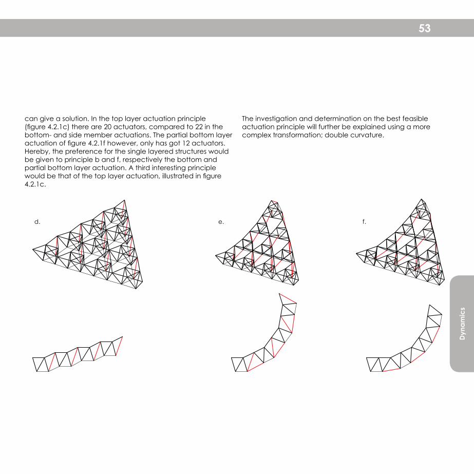
Fig 4.2.1 Concepts for actuationThe red lines show the actuated members in the structurea. Planar surfaceb. Actuation in the bottom layerc. Actuation in the top layerd. Actuation in side membersd. Combination of bottom layer actuation of the members between the grid unit cells and side member actuatione. Actuation of bottom layer members between the grid unit cells
Dyna
mic
s
53
can give a solution. In the top layer actuation principle (figure 4.2.1c) there are 20 actuators, compared to 22 in the bottom- and side member actuations. The partial bottom layer actuation of figure 4.2.1f however, only has got 12 actuators. Hereby, the preference for the single layered structures would be given to principle b and f, respectively the bottom and partial bottom layer actuation. A third interesting principle would be that of the top layer actuation, illustrated in figure 4.2.1c.
d. e. f.
The investigation and determination on the best feasible actuation principle will further be explained using a more complex transformation; double curvature.
4.2 Transformation Single curved structure
Michel Buijsen | 151 92 9823rd June 201154 Dynamic Space Frame Structure
Building Technology Graduation Project 2010-'11
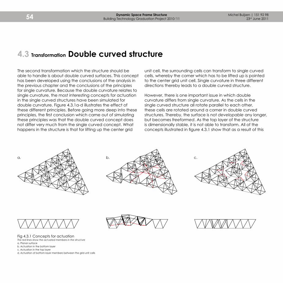
4.3 Transformation Double curved structure
a. b. c.
Fig 4.3.1 Concepts for actuationThe red lines show the actuated members in the structurea. Planar surfaceb. Actuation in the bottom layerc. Actuation in the top layerd. Actuation of bottom layer members between the grid unit cells
The second transformation which the structure should be able to handle is about double curved surfaces. This concept has been developed using the conclusions of the analysis in the previous chapter and the conclusions of the principles for single curvature. Because the double curvature relates to single curvature, the most interesting concepts for actuation in the single curved structures have been simulated for double curvature. Figure 4.3.1a-d illustrates the effect of these different principles. Before going more deep into these principles, the first conclusion which came out of simulating these principles was that the double curved concept does not differ very much from the single curved concept. What happens in the structure is that for lifting up the center grid
unit cell, the surrounding cells can transform to single curved cells, whereby the corner which has to be lifted up is pointed to the center grid unit cell. Single curvature in three different directions thereby leads to a double curved structure.
However, there is one important issue in which double curvature differs from single curvature. As the cells in the single curved structure all rotate parallel to each other, these cells are rotated around a corner in double curved structures. Thereby, the surface is not developable any longer, but becomes freeformed. As the top layer of the structure is dimensionally stable, it is not able to transform. All of the concepts illustrated in figure 4.3.1 show that as a result of this
Dyna
mic
s
55
d.
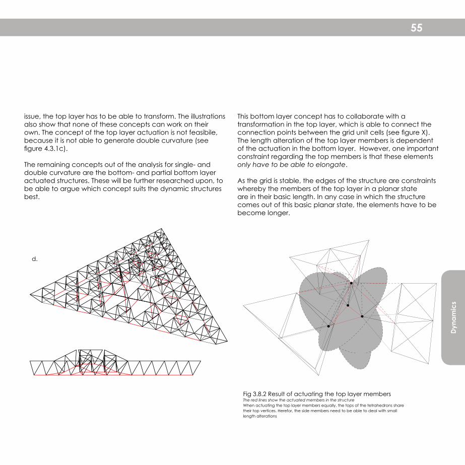
Fig 3.8.2 Result of actuating the top layer membersThe red lines show the actuated members in the structureWhen actuating the top layer members equally, the tops of the tetrahedrons share their top vertices. Herefor, the side members need to be able to deal with small length alterations
issue, the top layer has to be able to transform. The illustrations also show that none of these concepts can work on their own. The concept of the top layer actuation is not feasibile, because it is not able to generate double curvature (see figure 4.3.1c).
The remaining concepts out of the analysis for single- and double curvature are the bottom- and partial bottom layer actuated structures. These will be further researched upon, to be able to argue which concept suits the dynamic structures best.
This bottom layer concept has to collaborate with a transformation in the top layer, which is able to connect the connection points between the grid unit cells (see figure X). The length alteration of the top layer members is dependent of the actuation in the bottom layer. However, one important constraint regarding the top members is that these elements only have to be able to elongate.
As the grid is stable, the edges of the structure are constraints whereby the members of the top layer in a planar state are in their basic length. In any case in which the structure comes out of this basic planar state, the elements have to be become longer.
Michel Buijsen | 151 92 9823rd June 201156 Dynamic Space Frame Structure
Building Technology Graduation Project 2010-'11
4.4 Transformation of the structure
Fig 4.4.1 Grid unitOverview of vertices in perspective view
D
E F
C
AB
GH
H’
H’’
I
I’ I’’
G’’
G’
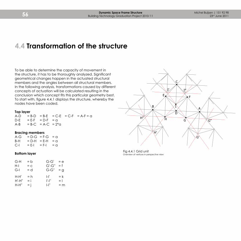
G-G' = eG'-G'' = fG-G'' = g
G-H = bH-I = cG-I = d
H-H' = hH'-H'' = iH-H'' = j
I-I' = kI'-I'' = lI-I'' = m
To be able to determine the capacity of movement in the structure, it has to be thoroughly analyzed. Significant geometrical changes happen in the actuated structural members and the angles between all structural members. In the following analysis, transformations caused by different concepts of actuation will be calculated resulting in the conclusion which concept fits this particular geometry best. To start with, figure 4.4.1 displays the structure, whereby the nodes have been coded.
Top layerA-D = B-D = B-E = C-E = C-F = A-F = aD-E = E-F = D-F = aA-B = B-C = A-C = 2*a
Bracing membersA-G = D-G = F-G = aB-H = D-H = E-H = aC-I = E-I = F-I = a
Bottom layer

Dyna
mic
s
57
ActuationIn order to further developed the transformations, it is important to know what maximal curvature the structure should be able to handle. This will result in length alterations of the linear elements and angular alterations for their connections to the nodes. To get more insight in the length- and angle variations, the section of the structure has been drawn for four different curvatures with a radius of 2, 3, 4 and
Fig 4.4.2 Bottom layer actuationa. Convex structure, radius 2 and 4 m.b. Convex structure, radius 3 and 5 m.
Fig 4.4.3 Partial bottom layer actuationa. Convex structure, radius 2 and 4 m.b. Convex structure, radius 3 and 5 m.
c. Concave structure, radius 2 and 4 m.d. Concave structure, radius 3 and 5 m.
c. Concave structure, radius 2 and 4 m.d. Concave structure, radius 3 and 5 m.
5 metres. This radius is measured from the actuated, layer of the structure. From the four different curved structures, three values can be extracted. The first one is the variation in length for the actuated members. The other two values concern the alterations in the angles between the beams. This important analysis will be applied on two different principles. The first one deals with actuated members in the entire bottom layer, the second one deals with partial bottom layer actuation.
b. b.
d. d.
a. a.
c. c.
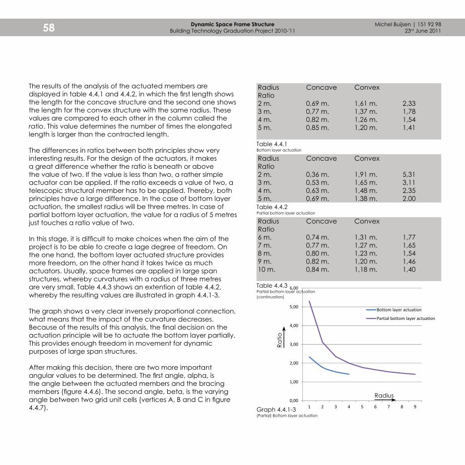
Michel Buijsen | 151 92 9823rd June 201158 Dynamic Space Frame Structure
Building Technology Graduation Project 2010-'11
0,00
1,00
2,00
3,00
4,00
5,00
6,00
1 2 3 4 5 6 7 8 9
Bottom layer actuation
Partial bottom layer actuation
Radius Concave Convex Ratio2 m. 0,69 m. 1,61 m. 2,333 m. 0,77 m. 1,37 m. 1,784 m. 0,82 m. 1,26 m. 1,545 m. 0,85 m. 1,20 m. 1,41
Radius Concave Convex Ratio2 m. 0,36 m. 1,91 m. 5,313 m. 0,53 m. 1,65 m. 3,114 m. 0,63 m. 1,48 m. 2,355 m. 0,69 m. 1,38 m. 2,00
Radius Concave Convex Ratio6 m. 0,74 m. 1,31 m. 1,777 m. 0,77 m. 1,27 m. 1,658 m. 0,80 m. 1,23 m. 1,549 m. 0,82 m. 1,20 m. 1,4610 m. 0,84 m. 1,18 m. 1,40
Table 4.4.1Bottom layer actuation
Table 4.4.2Partial bottom layer actuation
Table 4.4.3Partial bottom layer actuation (continuation)
Graph 4.4.1-3(Partial) Bottom layer actuation
Ratio
The results of the analysis of the actuated members are displayed in table 4.4.1 and 4.4.2, in which the first length shows the length for the concave structure and the second one shows the length for the convex structure with the same radius. These values are compared to each other in the column called the ratio. This value determines the number of times the elongated length is larger than the contracted length.
The differences in ratios between both principles show very interesting results. For the design of the actuators, it makes a great difference whether the ratio is beneath or above the value of two. If the value is less than two, a rather simple actuator can be applied. If the ratio exceeds a value of two, a telescopic structural member has to be applied. Thereby, both principles have a large difference. In the case of bottom layer actuation, the smallest radius will be three metres. In case of partial bottom layer actuation, the value for a radius of 5 metres just touches a ratio value of two.
In this stage, it is difficult to make choices when the aim of the project is to be able to create a lage degree of freedom. On the one hand, the bottom layer actuated structure provides more freedom, on the other hand it takes twice as much actuators. Usually, space frames are applied in large span structures, whereby curvatures with a radius of three metres are very small. Table 4.4.3 shows an extention of table 4.4.2, whereby the resulting values are illustrated in graph 4.4.1-3.
The graph shows a very clear inversely proportional connection, what means that the impact of the curvature decreases. Because of the results of this analysis, the final decision on the actuation principle will be to actuate the bottom layer partially. This provides enough freedom in movement for dynamic purposes of large span structures.
After making this decision, there are two more important angular values to be determined. The first angle, alpha, is the angle between the actuated members and the bracing members (figure 4.4.6). The second angle, beta, is the varying angle between two grid unit cells (vertices A, B and C in figure 4.4.7).
Radius
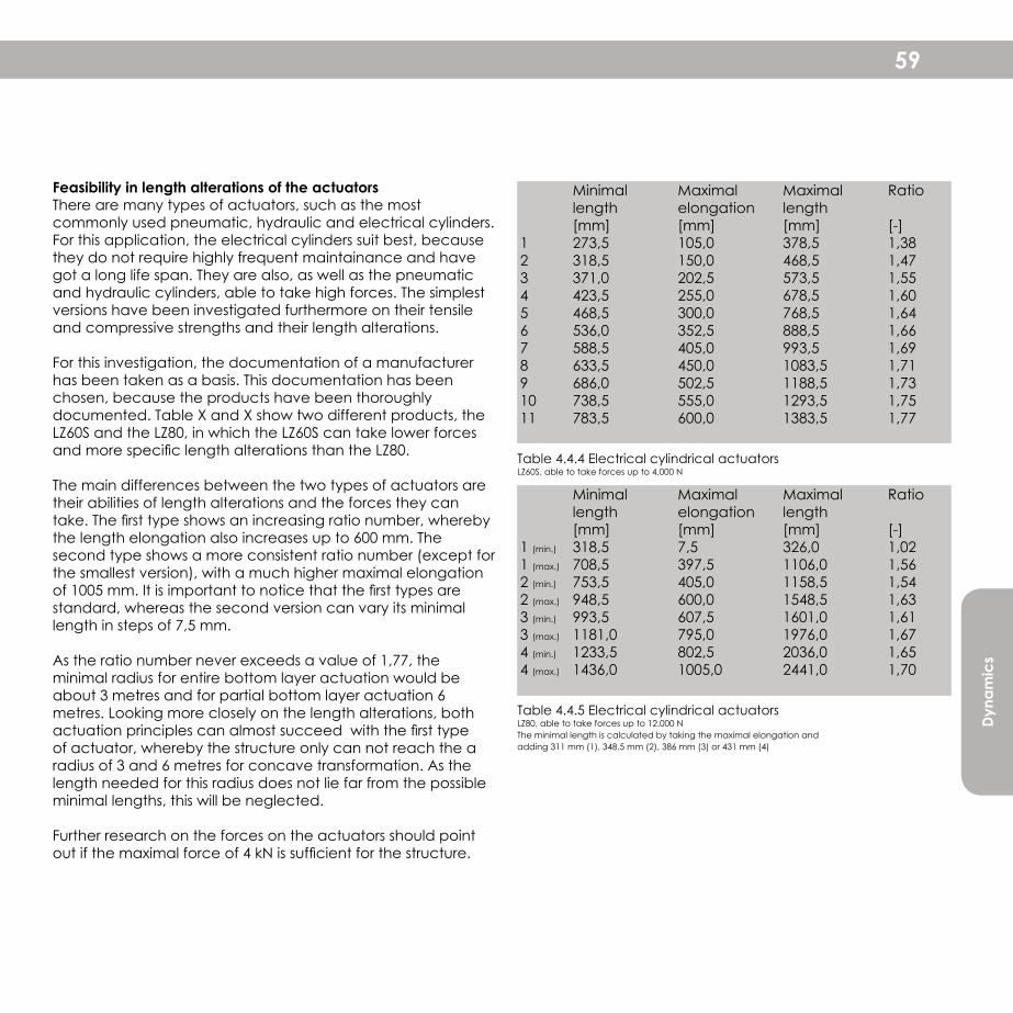
Dyna
mic
s
59
Minimal Maximal Maximal Ratio length elongation length [mm] [mm] [mm] [-]1 (min.) 318,5 7,5 326,0 1,021 (max.) 708,5 397,5 1106,0 1,562 (min.) 753,5 405,0 1158,5 1,542 (max.) 948,5 600,0 1548,5 1,633 (min.) 993,5 607,5 1601,0 1,613 (max.) 1181,0 795,0 1976,0 1,674 (min.) 1233,5 802,5 2036,0 1,654 (max.) 1436,0 1005,0 2441,0 1,70
Table 4.4.4 Electrical cylindrical actuatorsLZ60S, able to take forces up to 4.000 N
Table 4.4.5 Electrical cylindrical actuatorsLZ80, able to take forces up to 12.000 NThe minimal length is calculated by taking the maximal elongation and adding 311 mm (1), 348,5 mm (2), 386 mm (3) or 431 mm (4)
Feasibility in length alterations of the actuatorsThere are many types of actuators, such as the most commonly used pneumatic, hydraulic and electrical cylinders. For this application, the electrical cylinders suit best, because they do not require highly frequent maintainance and have got a long life span. They are also, as well as the pneumatic and hydraulic cylinders, able to take high forces. The simplest versions have been investigated furthermore on their tensile and compressive strengths and their length alterations.
For this investigation, the documentation of a manufacturer has been taken as a basis. This documentation has been chosen, because the products have been thoroughly documented. Table X and X show two different products, the LZ60S and the LZ80, in which the LZ60S can take lower forces and more specific length alterations than the LZ80.
The main differences between the two types of actuators are their abilities of length alterations and the forces they can take. The first type shows an increasing ratio number, whereby the length elongation also increases up to 600 mm. The second type shows a more consistent ratio number (except for the smallest version), with a much higher maximal elongation of 1005 mm. It is important to notice that the first types are standard, whereas the second version can vary its minimal length in steps of 7,5 mm.
As the ratio number never exceeds a value of 1,77, the minimal radius for entire bottom layer actuation would be about 3 metres and for partial bottom layer actuation 6 metres. Looking more closely on the length alterations, both actuation principles can almost succeed with the first type of actuator, whereby the structure only can not reach the a radius of 3 and 6 metres for concave transformation. As the length needed for this radius does not lie far from the possible minimal lengths, this will be neglected.
Further research on the forces on the actuators should point out if the maximal force of 4 kN is sufficient for the structure.
Minimal Maximal Maximal Ratio length elongation length [mm] [mm] [mm] [-]1 273,5 105,0 378,5 1,382 318,5 150,0 468,5 1,473 371,0 202,5 573,5 1,554 423,5 255,0 678,5 1,605 468,5 300,0 768,5 1,646 536,0 352,5 888,5 1,667 588,5 405,0 993,5 1,698 633,5 450,0 1083,5 1,719 686,0 502,5 1188,5 1,7310 738,5 555,0 1293,5 1,7511 783,5 600,0 1383,5 1,77

Michel Buijsen | 151 92 9823rd June 201160 Dynamic Space Frame Structure
Building Technology Graduation Project 2010-'11
Angle alphaVertex G G-A / G-G' G-A / G-G'' G-H / G-D G-I / G-FVertex G' G'-A / G'-G G'-A / G'-G''Vertex G'' G''-A / G''-G G''-A / G''-G'
Vertex H H-A / H-H' H-A / H-H'' H-I / H-E H-G / H-DVertex H' H'-A / H'-H H'-A / H'-H''Vertex H'' H''-A / H''-H H''-A / H''-H'
Vertex I I-A / I-I' I-A / I-I'' I-H / I-E I-G / I-FVertex I' I'-A / I'-I I'-A / I'-I''Vertex I'' I''-A / I''-I I''-A / I''-I'
Radius Concave Convex Range 2 m. 69,9° 36,2° 33,7°3 m. 67,4° 46,8° 20,6°4 m. 65,9° 50,9° 15,0°5 m. 64,9° 53,1° 11,8°
Radius Concave Convex Range 2 m. 40,2° 107,6° 67,4°3 m. 45,3° 86,4° 41,1°4 m. 48,3° 78,1° 29,8°5 m. 50,3° 73,8° 23,5°
Table 4.4.6Angle alpha
Table 4.4.7Angle beta
Fig 4.4.6 Angle alphaActuated members are indicated in red
Fig 4.4.7 Angle betaActuated members are indicated in red
D
E F
AB
GH
H’
H’’
I I
G’’
G’
DA
E
B
GH
H’
H’’
F
G’’
G’
Angle betaVertex A A-G / A-G' A-G' / A-G'' A-G / A-G''
Vertex B B-H / B-H' B-H' / B-H'' B-H /B-H''
Vertex C C-I / C-I' C-I / C-I'' C-I / C-I''
Vertex D D-H / D-G
Vertex E E-H / E-I
Vertex F F-I / F-G
CC
I’I’ I’’I’’
Angular transformation in the entire actuated bottom layer
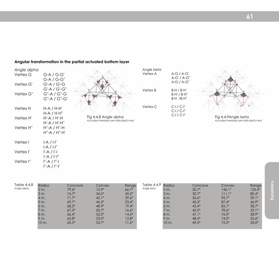
Dyna
mic
s
61
Angle alphaVertex G G-A / G-G' G-A / G-G''Vertex G' G'-A / G'-G G'-A / G'-G''Vertex G'' G''-A / G''-G G''-A / G''-G'
Vertex H H-A / H-H' H-A / H-H''Vertex H' H'-A / H'-H H'-A / H'-H''Vertex H'' H''-A / H''-H H''-A / H''-H'
Vertex I I-A / I-I' I-A / I-I''Vertex I' I'-A / I'-I I'-A / I'-I''Vertex I'' I''-A / I''-I I''-A / I''-I'
Radius Concave Convex Range2 m. 20,7° 146,1° 125,4°3 m. 30,7° 111,1° 80,4°4 m. 36,6° 95,7° 59,1°5 m. 40,5° 87,4° 46,9°6 m. 43,4° 82,1° 38,7°7 m. 45,5° 78,6° 33,1°8 m. 47,1° 76,0° 28,9°9 m. 48,4° 74,0° 25,6°10 m. 49,5° 72,5° 23,0°
Radius Concave Convex Range 2 m. 79,6° 12,9° 66,7°3 m. 74,7° 34,5° 40,2°4 m. 71,7° 42,1° 29,6°5 m. 69,7° 46,3° 23,4°6 m. 68,3° 48,9° 19,4°7 m. 67,3° 50,7° 16,6°8 m. 66,4° 52,0° 14,4°9 m. 65,8° 53,0° 12,8°10 m. 65,3° 53,7° 11,6°
Table 4.4.8Angle alpha
Table 4.4.9Angle beta
Fig 4.4.8 Angle alphaActuated members are indicated in red
Fig 4.4.9Angle betaActuated members are indicated in red
D D
E EF F
C C
A AB B
G GH H
H’ H’
H’’ H’’
I I
I’ I’I’’ I’’
G’’
G’’G’ G’
Angle betaVertex A A-G / A-G' A-G' / A-G'' A-G / A-G''
Vertex B B-H / B-H' B-H' / B-H'' B-H /B-H''
Vertex C C-I / C-I' C-I / C-I'' C-I / C-I''
Angular transformation in the partial actuated bottom layer
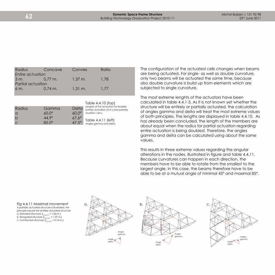
b. c.
Angles gamma Angles
gammaAngledelta
Angledelta
Michel Buijsen | 151 92 9823rd June 201162 Dynamic Space Frame Structure
Building Technology Graduation Project 2010-'11
Fig 4.4.11 Maximal movementA partially actuated structure is illustrated, the principle equals the entirely actuated structurea. Standard structure (lactuator = 1,00 m.)b. Elongated structure (lactuator = 1,37 m.)c. Contracted structure (lactuator = 0,74 m.)
a.
Angles gamma
Angledelta
Radius Gamma Deltaa 60,0° 60,0°b 44,9° 67,6°c 85,0° 47,5° Table 4.4.11 (left)
Angles gamma and delta
Table 4.4.10 (top)Lengths of the actuators for feasible entirely actuation (3 m.) and partially ctuation ( 6m.)
The configuration of the actuated cells changes when beams are being actuated. For single- as well as double curvature, only two beams will be actuated the same time, because also double curvature is build up from elements which are subjected to single curvature.
The most extreme lenghts of the actuators have been calculated in table 4.4.1-3. As it is not known yet whether the structure will be entirely or partially actuated, the calculation of angles gamma and delta will treat the most extreme values of both principles. The lengths are displayed in table 4.4.10. As has already been concluded, the length of the members are about equal when the radius for partial actuation regarding entire actuation is being doubled. Therefore, the angles gamma and delta can be calculated using about the same values.
This results in three extreme values regarding the angular alterations in the nodes, illustrated in figure and table 4.4.11. Because curvatures can happen in each direction, the members have to be able to rotate from the smallest to the largest angle. In this case, the beams therefore have to be able to be at a mutual angle of minimal 45° and maximal 85°.
Radius Concave Convex RatioEntire actuation3 m. 0,77 m. 1,37 m. 1,78Partial actuation6 m. 0,74 m. 1,31 m. 1,77
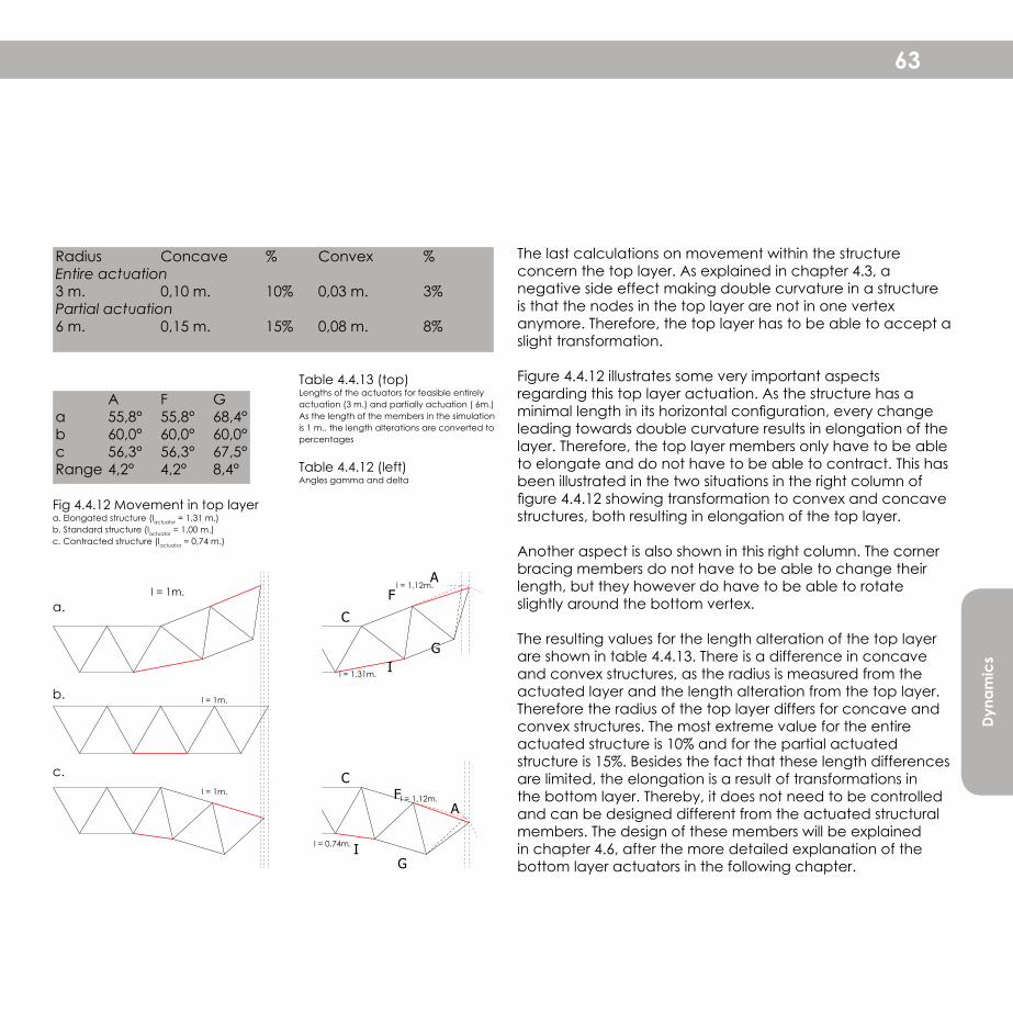
Dyna
mic
s
63
Fig 4.4.12 Movement in top layera. Elongated structure (lactuator = 1,31 m.)b. Standard structure (lactuator = 1,00 m.)c. Contracted structure (lactuator = 0,74 m.)
l = 1m.
A F Ga 55,8° 55,8° 68,4°b 60,0° 60,0° 60,0°c 56,3° 56,3° 67,5°Range 4,2° 4,2° 8,4°
Table 4.4.13 (top)Lengths of the actuators for feasible entirely actuation (3 m.) and partially actuation ( 6m.)As the length of the members in the simulation is 1 m., the length alterations are converted to percentages
Table 4.4.12 (left)Angles gamma and delta
c.
b.
a.
l = 1,12m.
l = 1m.
l = 1m.l = 1,12m.
l = 0,74m.
l = 1,31m.
F
F
C
C
A
A
G
G
I
I
Radius Concave % Convex %Entire actuation3 m. 0,10 m. 10% 0,03 m. 3%Partial actuation6 m. 0,15 m. 15% 0,08 m. 8%
The last calculations on movement within the structure concern the top layer. As explained in chapter 4.3, a negative side effect making double curvature in a structure is that the nodes in the top layer are not in one vertex anymore. Therefore, the top layer has to be able to accept a slight transformation.
Figure 4.4.12 illustrates some very important aspects regarding this top layer actuation. As the structure has a minimal length in its horizontal configuration, every change leading towards double curvature results in elongation of the layer. Therefore, the top layer members only have to be able to elongate and do not have to be able to contract. This has been illustrated in the two situations in the right column of figure 4.4.12 showing transformation to convex and concave structures, both resulting in elongation of the top layer.
Another aspect is also shown in this right column. The corner bracing members do not have to be able to change their length, but they however do have to be able to rotate slightly around the bottom vertex.
The resulting values for the length alteration of the top layer are shown in table 4.4.13. There is a difference in concave and convex structures, as the radius is measured from the actuated layer and the length alteration from the top layer. Therefore the radius of the top layer differs for concave and convex structures. The most extreme value for the entire actuated structure is 10% and for the partial actuated structure is 15%. Besides the fact that these length differences are limited, the elongation is a result of transformations in the bottom layer. Thereby, it does not need to be controlled and can be designed different from the actuated structural members. The design of these members will be explained in chapter 4.6, after the more detailed explanation of the bottom layer actuators in the following chapter.

Michel Buijsen | 151 92 9823rd June 201164 Dynamic Space Frame Structure
Building Technology Graduation Project 2010-'11
4.5 Bottom layer actuators
Fig 4.5.1 Geometrie of the structureTop view (left) and perspective view (right)
As a control for the feasibility, indicative structural calculations have been made. These calculations are able to give insight in the forces which run through the structure. The actuators, enabling the structure to move, should be able to take these forces. Reasonable forces which the actuator has to be able to handle, have been assumed from documentation. A comparison between different producers, shows that the maximal force for standard actuators is about 10 kN1.
The forces on the structure are based on dead load from a entire facade, consisting of the structure and a skin. As a material for the skin, glass, metal or cushions (ETFE-foil) have been assumed as being the materials which can be applied most likely. As a value for the dead load, the weight of the glass has been taken, because this is the highest own weight (about 50 kg/m2). The forces are (slightly) overdimensiond and also contains safety factors as prescribed by the NEN 6702.
The forces which the actuators have to be able to handle are calculated from the scheme, shown in figure 4.5.2. Because there is an equilibrium, the forces in point A equal zero. The load and lengths a and b are known, whereby the horizontal force can be calculated. The outcomes are displayed in table 4.5.1. There are a few variables in this calculation. The first one is the length of the beams. As there are no standard lengths, the calculation can show what will be the maximum length for a reasonable force. Then there are two results for the horizontal forces. The top table shows the forces in a half-actuated layer and the bottom one the forces in the entirely actuated layer. Hereby, the differences between the two versions can be taken into account when deciding upon the actuation of the structure.
1 Source: Documentatie RK Rose+Krieger, Drive Mechanisms (August 2009) from: www.rk-rose-krieger.com

Dyna
mic
s
65
Fig 4.5.3 Forces on the structurered dotted lines indicate the area in which the load is directed to the point loadTop view (left) and perspective view (right)
Table 4.5.1 Values for the dead- and live load
Dead load 2,2 kN/m2
Finishing layer 0,5 kN/m2
Fixing 0,2 kN/m2
Structure (own weight) 1,5 kN/m2
Assumption: load of the beams is 5 kg/m1 (0,05 kN/m1), nodes weigh about 20 kg (0,20 kN)One grid unit cell contains 21 beams (21 x 0,05 = 1,05 kN) and 9 nodes (9 x 0,2 = 1,8 kN), spread over about 2 m2)Live load 1 kN/m2
Fig 4.5.2 Schematic view on the forces through the structurea. Half actuated structureb. Actuated structure
a
a
b
b
V
VA
A
H
H

Michel Buijsen | 151 92 9823rd June 201166 Dynamic Space Frame Structure
Building Technology Graduation Project 2010-'11
Length of the beams [m1] 1 1,2 1,5 2 2,5Width of the truss [m1] 1 1,2 1,5 2 2,5Height of the truss [m1] 0,87 1,04 1,30 1,73 2,17Surface of each cell [m2] 0,43 0,62 0,97 1,73 2,71Surface for point loadsa [m2] 0,87 1,25 1,95 3,46 5,41 Dead loadb [kN/m2] 1,91 2,74 4,29 7,62 11,91Safety factor (1,2) [kN/m2] 2,29 3,29 5,14 9,15 14,29 Live loadc [kN/m2] 0,87 1,25 1,95 3,46 5,41Safety factor (1,5) [kN/m2] 1,30 1,87 2,92 5,20 8,12 Load [kN] 3,59 5,16 8,07 14,34 22,41a Each point load is connected to six triangles, of which it receives 1/3 of the loadb The dead load, determined in table X, multiplied by the surface for point loadc The live load, determined in table X, multiplied by the surface for point load
Table 4.5.2 Calculation of the forces on the structure
Table 4.5.3 Calculation of the force in the actuatorFor both the half actuated and the actuated grid
Half-actuated layera m 1 1,2 1,5 2 2,5b m 0,87 1,04 1,30 1,73 2,17F kN 3,59 5,16 8,07 14,34 22,41V kN 7,17 10,33 16,13 28,68 44,82Hd kN 8,3 11,9 18,6 33,1 51,8 Actuated layer a m 1 1,2 1,5 2 2,5b m 0,87 1,04 1,30 1,73 2,17F kN 3,59 5,16 8,07 14,34 22,41V kN 7,17 10,33 16,13 28,68 44,82Hd kN 4,1 6,0 9,3 16,6 25,9d In case of equilibrium, the sum of forces in point A is zero. Then: V x a = H x bThe horizontal force equals the force in the actuators
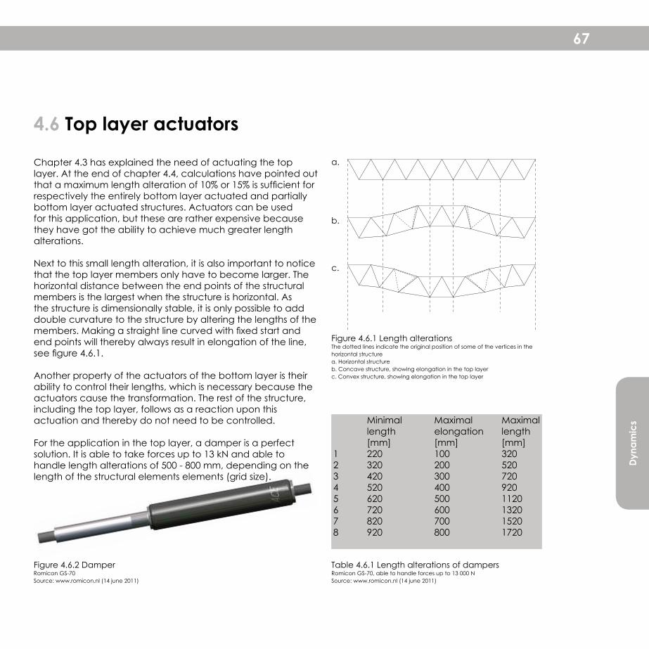
Dyna
mic
s
67
Figure 4.6.2 DamperRomicon GS-70Source: www.romicon.nl (14 june 2011)
Table 4.6.1 Length alterations of dampersRomicon GS-70, able to handle forces up to 13 000 NSource: www.romicon.nl (14 june 2011)
Figure 4.6.1 Length alterations The dotted lines indicate the original position of some of the vertices in the horizontal structurea. Horizontal structureb. Concave structure, showing elongation in the top layerc. Convex structure, showing elongation in the top layer
4.6 Top layer actuators
Chapter 4.3 has explained the need of actuating the top layer. At the end of chapter 4.4, calculations have pointed out that a maximum length alteration of 10% or 15% is sufficient for respectively the entirely bottom layer actuated and partially bottom layer actuated structures. Actuators can be used for this application, but these are rather expensive because they have got the ability to achieve much greater length alterations.
Next to this small length alteration, it is also important to notice that the top layer members only have to become larger. The horizontal distance between the end points of the structural members is the largest when the structure is horizontal. As the structure is dimensionally stable, it is only possible to add double curvature to the structure by altering the lengths of the members. Making a straight line curved with fixed start and end points will thereby always result in elongation of the line, see figure 4.6.1.
Another property of the actuators of the bottom layer is their ability to control their lengths, which is necessary because the actuators cause the transformation. The rest of the structure, including the top layer, follows as a reaction upon this actuation and thereby do not need to be controlled.
For the application in the top layer, a damper is a perfect solution. It is able to take forces up to 13 kN and able to handle length alterations of 500 - 800 mm, depending on the length of the structural elements elements (grid size).
Minimal Maximal Maximal length elongation length [mm] [mm] [mm]1 220 100 3202 320 200 5203 420 300 7204 520 400 9205 620 500 11206 720 600 13207 820 700 15208 920 800 1720
a.
b.
c.

Michel Buijsen | 151 92 9823rd June 201168 Dynamic Space Frame Structure
Building Technology Graduation Project 2010-'11
The study on the dynamics of the geometry started with an investigation on the effect of actuating different groups of structural members. The most interesting principle contains actuated members in the bottom layer of the structure, whereby the tetrahedrons can be rotated around a central triangle. A variation on this principle is the partially actuated bottom layer, whereby the grid unit cells cannot transform, but are able to rotate around each other.
Both concepts have got potential and each has got its own (dis-)advantages. The study on the actuation of the structure continued with both principles. Specific investigations on for example the lengths and forces on the structural elements should be able to point out the most feasible option for single and double curvature.
SIngle- and double curvatureThere is a fundamental difference between these types of transformations. Whereas single curvature is rather simple to realise, double curvature is far more difficult. The difference between these transformations is that the grid unit cells in the single curved structure transform parallel to each other in one direction. In double curvature, the cells have to rotate in all three directions of the central triangle. The main problem of double curvature however, is that the grid is dimensionally stable. Hereby it is only able to transform as a developable surface, whereas double curvature is a freeform surface. The only solution to be able to achieve double curvature is by actuating both layers. It has already been conclused that actuating the bottom layer functions very well to achieve transformations. This conclusion proves that it is also necessary to actuate the top layer of the structure.
Structural elementsNow that it is clear that actuation will happen in the (partial or entire) bottom layer and the top layer. The next step is to take a closer look on what exactly happens in the different
4.7 Conclusion
elements. The structural members consist of nodes, bars and actuators for the bottom and top layer. The following aspects have been investigated:
- Maximal achievable radius- Angular alterations in the nodes- Force which the actuator has to be able to handle- Standard length of the linear elements (bars and actuators)- Minimal and maximal length of actuators in the bottom and the top layer to achieve the maximal radius
These aspects have all been applied on both the partially and the entirely actuated bottom layer. After comparing the different advantages and disadvantages, a choice can be made which can be further developed. As the entirely bottom layer actuated structure contains twice as much actuators, it is able to handle a twice as small radius of 3 metres instead of 6 metres. These minimal radii have been determined by comparing the minimal and maximal length of real actuators with those needed to achieve the radius. As in this phase the standard length is not known yet, a more universal value has been introduced: the ratio. This is the value with which the minimal length has to be multiplied to get the maximal length.
Independent on the standard lengths, the radii enable the possibility to calculate the angular alterations in the nodes. It might make sense that the alterations in the entirely actuated structure are twice as small as those in the partially actuated structure. The smaller these alterations are, the less complicated and less large the nodes become. For this aspect again, the entirely actuated bottom layer structure has got important advantages.
The calculation of the forces which run through the structure are related to the lengths of the structural elements and the forces which the actuators have to be able to handle. As it is known that the actuators can handle up to 13 kN, the question is how large the forces will be for different lengths.
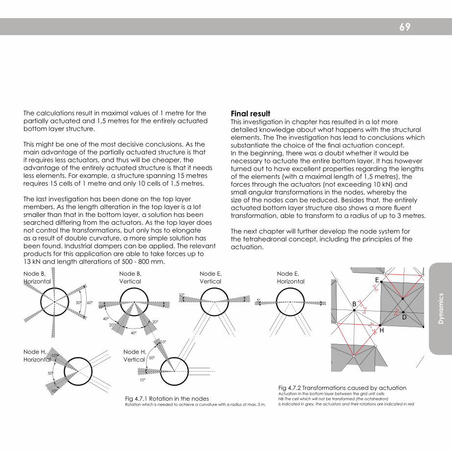
Dyna
mic
s
69
Node E, Vertical
Node B, Vertical
Node B, Horizontal
50° 60°
10°
50°
10°
10°5°
40°20°
40°
20°
10°
10°
50°10°Node H, Horizontal
Node H, Vertical
Node E, Horizontal
Fig 4.7.1 Rotation in the nodesRotation which is needed to achieve a curvature with a radius of max. 3 m.
Fig 4.7.2 Transformations caused by actuationActuation in the bottom layer between the grid unit cellsNB The cell which will not be transformed (the octahedron)is indicated in grey, the actuators and their rotations are indicated in red
E
D
H
B
The calculations result in maximal values of 1 metre for the partially actuated and 1,5 metres for the entirely actuated bottom layer structure.
This might be one of the most decisive conclusions. As the main advantage of the partially actuated structure is that it requires less actuators, and thus will be cheaper, the advantage of the entirely actuated structure is that it needs less elements. For example, a structure spanning 15 metres requires 15 cells of 1 metre and only 10 cells of 1,5 metres.
The last investigation has been done on the top layer members. As the length alteration in the top layer is a lot smaller than that in the bottom layer, a solution has been searched differing from the actuators. As the top layer does not control the transformations, but only has to elongate as a result of double curvature, a more simple solution has been found. Industrial dampers can be applied. The relevant products for this application are able to take forces up to 13 kN and length alterations of 500 - 800 mm.
Final resultThis investigation in chapter has resulted in a lot more detailed knowledge about what happens with the structural elements. The The investigation has lead to conclusions which substantiate the choice of the final actuation concept. In the beginning, there was a doubt whether it would be necessary to actuate the entire bottom layer. It has however turned out to have excellent properties regarding the lengths of the elements (with a maximal length of 1,5 metres), the forces through the actuators (not exceeding 10 kN) and small angular transformations in the nodes, whereby the size of the nodes can be reduced. Besides that, the entirely actuated bottom layer structure also shows a more fluent transformation, able to transform to a radius of up to 3 metres.
The next chapter will further develop the node system for the tetrahedronal concept, including the principles of the actuation.
70
Fuksas (2010) Entrance building Admirant, Eindhoven

71
5 The constraints for the design of the structural elements have been made in the previous chapter concerning the dynamics. This chapter starts with a precedent study which will lead to concepts for dynamic structural elements. These concepts will be analyzed, resulting in a final design.
Structural elements
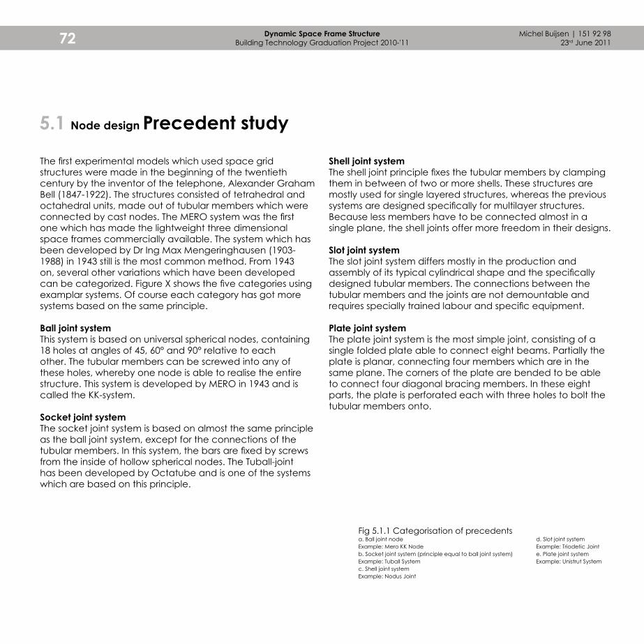
Michel Buijsen | 151 92 9823rd June 201172 Dynamic Space Frame Structure
Building Technology Graduation Project 2010-'11
Shell joint systemThe shell joint principle fixes the tubular members by clamping them in between of two or more shells. These structures are mostly used for single layered structures, whereas the previous systems are designed specifically for multilayer structures. Because less members have to be connected almost in a single plane, the shell joints offer more freedom in their designs.
Slot joint systemThe slot joint system differs mostly in the production and assembly of its typical cylindrical shape and the specifically designed tubular members. The connections between the tubular members and the joints are not demountable and requires specially trained labour and specific equipment.
Plate joint systemThe plate joint system is the most simple joint, consisting of a single folded plate able to connect eight beams. Partially the plate is planar, connecting four members which are in the same plane. The corners of the plate are bended to be able to connect four diagonal bracing members. In these eight parts, the plate is perforated each with three holes to bolt the tubular members onto.
The first experimental models which used space grid structures were made in the beginning of the twentieth century by the inventor of the telephone, Alexander Graham Bell (1847-1922). The structures consisted of tetrahedral and octahedral units, made out of tubular members which were connected by cast nodes. The MERO system was the first one which has made the lightweight three dimensional space frames commercially available. The system which has been developed by Dr Ing Max Mengeringhausen (1903-1988) in 1943 still is the most common method. From 1943 on, several other variations which have been developed can be categorized. Figure X shows the five categories using examplar systems. Of course each category has got more systems based on the same principle.
Ball joint systemThis system is based on universal spherical nodes, containing 18 holes at angles of 45, 60° and 90° relative to each other. The tubular members can be screwed into any of these holes, whereby one node is able to realise the entire structure. This system is developed by MERO in 1943 and is called the KK-system.
Socket joint systemThe socket joint system is based on almost the same principle as the ball joint system, except for the connections of the tubular members. In this system, the bars are fixed by screws from the inside of hollow spherical nodes. The Tuball-joint has been developed by Octatube and is one of the systems which are based on this principle.
5.1 Node design Precedent study
Fig 5.1.1 Categorisation of precedents a. Ball joint nodeExample: Mero KK Nodeb. Socket joint system (principle equal to ball joint system)Example: Tuball Systemc. Shell joint systemExample: Nodus Joint
d. Slot joint systemExample: Triodetic Jointe. Plate joint systemExample: Unistrut System

Stru
ctur
al e
lem
ents
73
a. b.
c. d. e.

Michel Buijsen | 151 92 9823rd June 201174 Dynamic Space Frame Structure
Building Technology Graduation Project 2010-'11
AnalysisThe analysis of the different categories of precedents has lead to several important conclusions. It can be noticed that the concepts differ a lot, while they are developed for the same purpose: to build a space frame structure. As the nodes do not differ in their purpose, the differences can be traced back in other aspects. The most important one is the way they are produced and assembled on site. Next to these technological aspects is the impact of the designs on the aesthetics. The most relevant issue for this research relates mostly to the technological part, but the central question in the precedent study is which of the design aspects of these five concepts can be relevant for dynamic structures?
5.2 Node design Analysis and Design
a.b.
The first thing that can be noticed when comparing the precedents is the way in which the concept influences the shapes. The socket joint system shows only a slight variation on the ball joint because they differ in the way the tubular members are connected. This results in a 'cleaner' aesthetic for the socket joint system. The shell joints are based on the same principle of connecting tubular members to a three dimensionally shaped form, but this principle offers more freedom in their designs.
The slot joint system mostly differs in the connection of the tubular members to the nodes. This connection is very specifically shaped and not demountable. The plate joint system differs in the connections to the tubular members as well as in the node design. It is a variation on the shell joint system, in which the plate joints consist of only one element whereas the shell joints contain several elements which are bolted or welded together.

Stru
ctur
al e
lem
ents
75
Design The difference between the previous systems and the system for dynamic structures is that the joints in dynamic structures have to contain moving elements. This brings along the following important requirements:
- Isotropic formIt is recommended that the form of the node has to be the same in each direction. If this is not the case, it will be hard to design the node and its connections universally as each connection will differ in its detailing. The basic shapes which are isotropic are basically the sphere and derived from this are shells and rings. Furthermore, a cylindrical shape is also isotropic but only in one plane.
Fig 5.2.1 Node concepts for dynamic structures a. Ball joint nodeb. Shell joint systemc. Ring joint systemd. Plate joint system
c. d.
- Centric forcesBecause the dynamic structure will have to be able to change its configuration, the connection points of the tubular members on the joints will also rotate. It is important to be sure that the forces which run through the structure (tubular members and the node) run centric through one point. Otherwise, the structure will show unwanted deformations, causing friction in the nodes.
Because of the requirement of the nodes to be isotropic, a sphere is the basic form for the node designs. Figure 5.2.1 shows variations on the five mentioned categories. However, figure 5.2.1a is the only concept which shows a spherical node. The other concepts are abstractions of a sphere, resulting in different properties regarding rotational freedom and structural behaviour. The explanation of these concepts and their feasibility for this project will be described on the following pages.
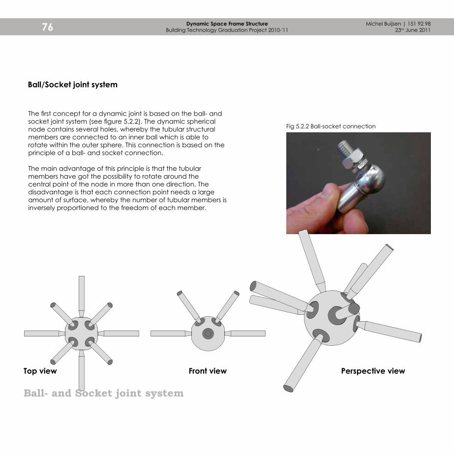
Michel Buijsen | 151 92 9823rd June 201176 Dynamic Space Frame Structure
Building Technology Graduation Project 2010-'11
Ball- and Socket joint system
Ball/Socket joint system
The first concept for a dynamic joint is based on the ball- and socket joint system (see figure 5.2.2). The dynamic spherical node contains several holes, whereby the tubular structural members are connected to an inner ball which is able to rotate within the outer sphere. This connection is based on the principle of a ball- and socket connection.
The main advantage of this principle is that the tubular members have got the possibility to rotate around the central point of the node in more than one direction. The disadvantage is that each connection point needs a large amount of surface, whereby the number of tubular members is inversely proportioned to the freedom of each member.
Top view Perspective viewFront view
Fig 5.2.2 Ball-socket connection

Stru
ctur
al e
lem
ents
77
Shell joint system
Shell joint system
The second concept is based on shell joint systems. For this concept, the sphere has been splitted into several parts which are able to rotate over one another (see figure 5.2.3). The tubular members are connected to a connecting element which is able to rotate over the shells. In this system, rotation in one directionis provided by rotating the shells and rotation in its perpendicular direction is provided by rotating the connecting elements. This results in a joint in which the range of rotation is splitted in two directions, creating different elements and details. The rotation of the shells over the central axis offer less freedom than the rotation of the beams over these shells. Therefore, a joint can be positioned in a way in which it fits the needed rotational freedom best.
Top view Perspective viewFront view
Fig 5.2.3 Shells

Michel Buijsen | 151 92 9823rd June 201178 Dynamic Space Frame Structure
Building Technology Graduation Project 2010-'11
Slot / Ring joint system
Ring joint system
Next to shells, rings are also abstractions of a sphere. The rings can be rotated one-directionally over a central axis, whereby connection elements can be rotated in the perpendicular direction. So far this principle is very much like the Shell joint system. There is an important diffence regarding the rotational freedom which can be achieved, because as the rings have got a smaller width, they can handle more rotation.
Several concepts for the ring joint system have been developed, resulting in the illustrated concept. The earlier concepts will be explained on the following pages.
Top view Perspective viewFront view
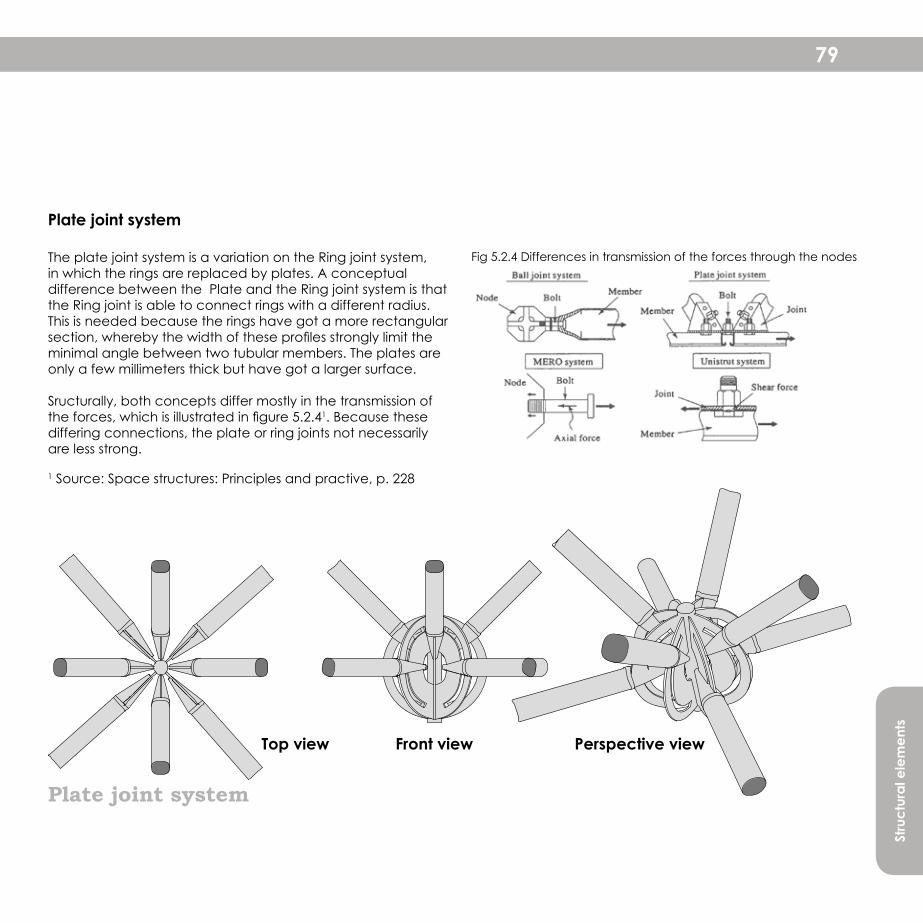
Stru
ctur
al e
lem
ents
79
Plate joint system
Plate joint system
The plate joint system is a variation on the Ring joint system, in which the rings are replaced by plates. A conceptual difference between the Plate and the Ring joint system is that the Ring joint is able to connect rings with a different radius. This is needed because the rings have got a more rectangular section, whereby the width of these profiles strongly limit the minimal angle between two tubular members. The plates are only a few millimeters thick but have got a larger surface.
Sructurally, both concepts differ mostly in the transmission of the forces, which is illustrated in figure 5.2.41. Because these differing connections, the plate or ring joints not necessarily are less strong.
1 Source: Space structures: Principles and practive, p. 228
Top view Perspective viewFront view
Fig 5.2.4 Differences in transmission of the forces through the nodes

Michel Buijsen | 151 92 9823rd June 201180 Dynamic Space Frame Structure
Building Technology Graduation Project 2010-'11
Wooden model showing the gyroscopic principle
5.3 Node design Model study
After the development of the conceptual nodes, resulting out of a precedent analysis, some physical models have been made. The former product design project had already proved that making prototypes is very important for the process, as every small detail has to be known to be able to make one.
The project of the MSc1 studio focused on the design of a standard node which could be applied in various static double curved structures. The aim of this project was to create a universal node, which is able to receive at least six beams from multiple directions. The final model shows a ring-concept in which three rings are able to rotate inside one another. Every ring creates a 'surface', whereby every beam which lies in this surface can be connected. Because two lines are able to define a surface, each ring can connect to at least two beams, wherefore it has to be able to rotate three dimensionally in every position. The concept seems rather simple, but detailing this node deserved special attention. The node consists of three rings, which are connected by connection points which have to be able to move around the
Fig 5.3.1 Conceptual model of the gyroscopic principle

Stru
ctur
al e
lem
ents
81
Fig 5.3.2 Exploded view of final model
rings. These are hard to detail because they have to be able to redirect the forces through the structure, while they are also the weakest link. Another complex detail concerns the connection between the beams and the rings. These connection points have on the one hand to be as small as possible, because enlarging the connection points has a high impact on the ability of the rings to rotate and on the angles between the beams. On the other hand, enlarging the connecting elements improves the redirectioning of the forces through the beams, the elements and to the rings.
Next to these advantages and disadvantages, the model has been tested on structural properties. It has been modeled in Diana, whereby it has showed that the rings have to be detailed as being connected to each other. Hereby the deformation of the rings caused by the forces will be reduced. Too large deformations can result in friction of the rings, which is of course not desired.
The complexity and potential of this model have stimulated to continue the research in this graduation study. The positive and negative aspects which have been explained will strongly influence the design of the node for the dynamic structure.
1:1 Gyroscopic node prototype containing rings and connections to the tubular members

Michel Buijsen | 151 92 9823rd June 201182 Dynamic Space Frame Structure
Building Technology Graduation Project 2010-'11
From the four concepts which have been illustrated (5.2), a prototype has been made of two concepts. The ring joint in first instance looks kind of similar to the ring concept. However, it contains improvements which react upon the disadvantages of the gyroscopic model. The concept resulted in complex detailing between the rings to make it possible for the rings to rotate to any desired plane. For example, the inner ring rotates around 1 axis. Hereby, the ring cannot be positioned in any desired surface. Herefore, the middle ring has to be rotated, whereby the connection points to the smaller ring rotates along. It will not be surprising that this is very hard to achieve.
Therefore, the ring concept is based on half rings, which rotate around one central axis. Only one beam will be connected to each ring, whereby it is easier to position each beam. Also, the rings are only made in two different sizes. The third, inner ring of the gyroscopic model showed a considerably lower freedom in rotation, because the circumference is smaller and the elements connecting the beams to the nodes will be able to rotate in a smaller angle.
The ring concept offers better possibilities, because a lot of problems of the gyroscopic model have already been solved. However, it still contains the crucial details of the connections of the beams to the rings and the connection of the rings to the central axis. A second model is based on a plate joint, whereby the rings have been replaced by plates. The main difference between the plate- and ring joint is the way they redirect the forces, which has been illustrated in figure 5.2.4. Both the ring- and the plate joint have been made using 2 different ways of making the central axis. The first one is a cylinder with the same height as the rings, whereby the rings and plates are connected to one element. In the second version, the middle of the axis has been removed to create an empty center and thereby a visually lighter node. The models show that this version results in an unstable node, whereby this last version is not feasible.
The other concepts of the ball- and segment joint are more difficult to be made, because it is hard to model a spherical node. Therefore the models are first simulated and thereafter roughly modeled.
Ring joint model with central axis (middle, stable) and without central axis (right, unstable)
Prototyping the node
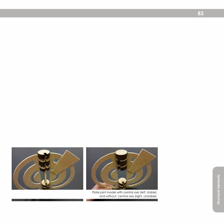
Stru
ctur
al e
lem
ents
83
Plate joint model with central axis (left, stable) and without central axis (right, unstable)

Michel Buijsen | 151 92 9823rd June 201184 Dynamic Space Frame Structure
Building Technology Graduation Project 2010-'11
During the development of the calculations of the dynamics in the nodes, the ball concept came forward as the most intesting concept because some members had to be fixed and others (actuators) had to be abe to move within a small range in vertical and horizontal directions. The calculations had resulted in some numbers, which are illustrated in figure 5.3.4. These have been modeled in the prototype which is showed at the bottom of this page.
This is a rough abstraction of the real model. During further development, this nodular system seemed most feasible as being the final system. Therefore, it has been modeled more detailed later on in the process. This will be shown in the part of the final structural design (5.4).
Joint showing freedom in horizontal rotation (left) and vertical rotation (right)
Fig 5.3.3 Conceptual illustration of the ball joint system
Figure 5.3.4Required freedom in the nodea. Freedom in horizontal movement (top view)b. Freedom in horizontal movement (perspective view)c. Freedom in vertical movement (section view)d. Freedom in vertical movement (perspective view)
b.
d.
a.
c.
60°
130°
52,5°
52,5°
20°20°
25°
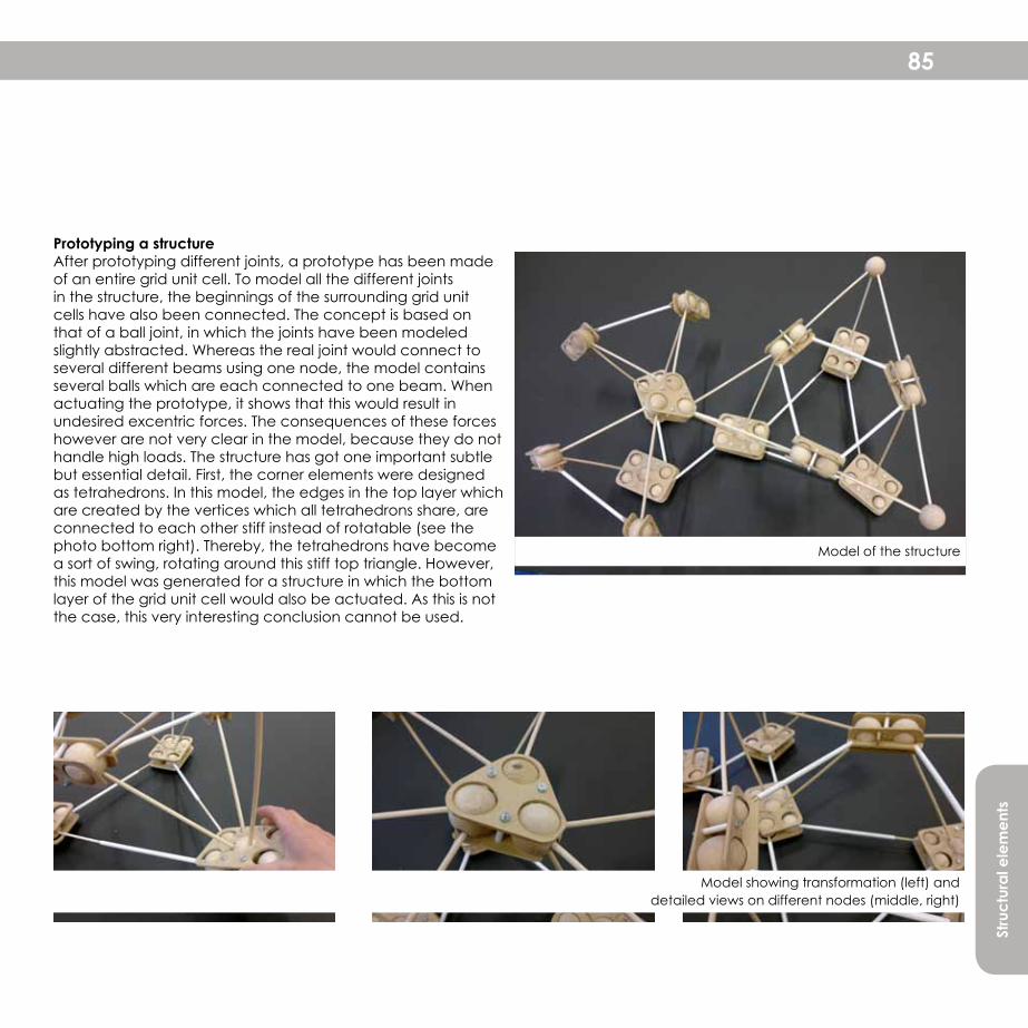
Stru
ctur
al e
lem
ents
85
Model showing transformation (left) and detailed views on different nodes (middle, right)
Model of the structure
Prototyping a structureAfter prototyping different joints, a prototype has been made of an entire grid unit cell. To model all the different joints in the structure, the beginnings of the surrounding grid unit cells have also been connected. The concept is based on that of a ball joint, in which the joints have been modeled slightly abstracted. Whereas the real joint would connect to several different beams using one node, the model contains several balls which are each connected to one beam. When actuating the prototype, it shows that this would result in undesired excentric forces. The consequences of these forces however are not very clear in the model, because they do not handle high loads. The structure has got one important subtle but essential detail. First, the corner elements were designed as tetrahedrons. In this model, the edges in the top layer which are created by the vertices which all tetrahedrons share, are connected to each other stiff instead of rotatable (see the photo bottom right). Thereby, the tetrahedrons have become a sort of swing, rotating around this stiff top triangle. However, this model was generated for a structure in which the bottom layer of the grid unit cell would also be actuated. As this is not the case, this very interesting conclusion cannot be used.

Michel Buijsen | 151 92 9823rd June 201186 Dynamic Space Frame Structure
Building Technology Graduation Project 2010-'11
5.4 Node design Final Node Designs
The final structural design is the finishing part of the research. After the investigation on geometry had resulted in the tetrahedronal structure and the study on actuation has investigated on the elements could best be actuated, the angular transformations have been determined. This chapter has dealt with a few concepts for the node structure, which has lead to this final result. Because of the large number of structural members which can be fixed on the node and the small transformations in the connections to the nodes which are needed by the actuators, the ball concept is the most interesting one.
The most logical solution for detailing the node has been illustrated in figure 5.4.1. Prototyping this node has gained more insight in how this idea would actually work in practice. A steel node has been adjusted for this dynamic application by making larger holes and making the connection points of the rotatable structural elements. The result of this prototype is a very elegant node, in which the structural elements are able to rotate in the degrees of freedom as have been calculated.
Photos of the prototype, showing only the fixed beams (left), the fixed and moving beams (middle) and the inside of the node (right)
However, the bars of the structure do not rotate optimally in their connection points because there is a lot of friction. This is also necessary, because otherwise the bars could show unwanted rotations, whereby they would not point to the center of the node and the forces would go excentric.
An alternative detail has been developed while thinking of better connection points. Hereby, the bars are connected to balls, which can be enclosed in the node like a ball- and socket connection. The advantage of this solution would be that the balls have got less friction, whereby a smoother rotation would be allowed. The disadvantage however of this solution is that forces would run excentric. Thereby, this solution is feasible only in the partially actuated bottom layer structure, as discussed in chapter 4. The difference of this structure regarding the entirely actuated bottom layer structure is that it also contains four fixed beams, able to keep the node on its position and handle the excentric forces. The solution for the entirely actuated bottom layer structure is feasible, however more complicated to detail and produce.

Stru
ctur
al e
lem
ents
87
Pop stages are getting more interactive; moving elements and video screens. When is the time for moving stages?Queensday 2011 at the Museumplein, Amsterdam (30-04-2011)
Moulded end piecesFixed connectionRotatable connection
TeflonHole Ø 40 mm Steel bars, Ø50mm
5.5 Conclusion
The research on the node systems has been developed separately from the development of the geometry and dynamics. Hereby, some ideas for the nodes have already been tested before the investigation on the exact properties of the node had finished. The general part of this chapter focused on different concepts, which were all based on (parts of) a sphere. The most interesting concept was the ball concept, which is able to handle fixed connections very well as well as dynamic connections. Thereby it is also a very elegant design, which does not very obviously show the details which are necessary to connect the dynamic elements.
Prototyping the node has revealed some interesting results. The conclusion from chapter 4, dynamics, was that the entirely actuated bottom layer structure was far more interesting to develop. However, detailing the nodes offered some new insights. When comparing the details of both structures, see
figure X and X, the partially actuated structure has got some advantages because each node contains three dynamic and four fixed connections, whereas the entirely actuated bottom layer has got five dynamic and two fixed connections. Because the partially actuated structure has got fixed connections, it matters less that forces would not run centric through the node. Therefore, this partially actuated concept allows less complicated detailing, whereby the dynamic connections can be realised by balls which have got less friction in rotating than the shell-like components from the entirely actuated structure.
The entirely actuated bottom layer structure is realisable, but contains more complicated details. Therefore, the partially actuated bottom layer structure is a highly interesting alternative although it offers less freedom, less elegant transformations and shorter structural members.
Fig. 5.4.1 Detail of the node
88
The results of this research on the innovative field of dynamic structures are only the top of the iceberg. The project boundaries of this research were very helpful to focus on specific problems which were solved. These same boundaries have also left a lot of aspects empty which can now be researched upon. Next to these issues, during the process also a lot of new possibilities showed up which could be developed in a later stadium. These possibilities mainly concern specific properties which the structure needs for specific purposes. The main important items for future developments are summed up.
Building skinOne of the main elements which was left out by the project boundaries was the building skin. A very extensive research can be done on several aspects regarding the skin such as the materialisation and its connection to the structure. The main complexity of this research would be that the flexible structure also needs materialisation which is able to handle curved surfaces or planar elements which are flexible connected as a result of subdividing the curved surface into planar elements.
Connection of the structure to the buildingThe geometry of the structure is designed as being floating in the air, which is of course not possible. The structure has to be connected to a floor or vertical elements such as a facade, a wall or columns. The first case would be the most interesting to research upon, because this structure would be fully independent of other elements. A first step can therefore be taken by regarding the maximal span of the structure. This will determine if a structure is able to stand by itself. If this is not the case, columns or other vertical structural members are needed. A very interesting field for investigation lies in how these vertical members would best fit to the philosophy of the structure.
Besides these further investigations, it is also important to evaluate on this project by further developing the structure towards a 1:1 mock-up. This final stage has been approached, but seemed too hard to reach within a research project of half a year.
ApplicationIt was very helpful for the research to not focus on a single application at once. Now this project has resulted in interesting conclusions, these can be taken to higher grounds. By confronting the structure with a specific architectural design, it will become clear what the product already has got to offer and which points of attention have to be explored to make it feasible.
One of the most interesting applications is that of temporary structures, pavilions and coverings. For the sake of the feasibility, applying this dynamic structure brings some important properties along.
Deployable structureOne of the applications for which this system could be used is (temporary) single storey pavilions. The dynamic structure is able to trigger people to visit the pavilion, whereby it can travel all over the world. Because of the short-time period in which the structure stays on the same location, maintenance can be done when traveling to another location. To make this field of application more interesting, the structure should have to be moved without needing lots of containers and trucks. Deployable structures are specifically designed for purposes whereby they need to be able to contract in very small pieced and also extend into an enourmous structure. A very nice examples of one of the earliest developments of this kind of structures is the roof covering for the swimming pool, developed by Escrig Valcarcel Sanchez (1965). Further research can focus upon the possibilities and requirements of structures in terms of deployment.
Future possibilities

89
Fig. 6.1.1 Roof covering for swimming poolEscrig Valcarcel Sanchez (1965)

90
The introduction to this graduation study ihas already been two years ago in the spring semester of 2009 of the MSc1 Building Technology product design studio. From that project on, I wanted to research on this field of innovation. When the time came to start the project in the spring semester of 2010 (MSc3 Materialisation studio) the subject has been introduced as a proposal for the course of 'the Future Evelop'. After finishing my architectural graduation project at the end of december 2010, the research started.
During the development of the project, the time has passed rapidly. It was a very interesting process, in which I, fortunately, had very few ´downs´ a lots of ´ups´. In the beginning, I had to find my way in researching. However, this was solved quickly when I was asked to stop writing and start puzzling. I think this was an important step; to let me be guided by the process of the research development, not trying to take too much control by myself.
EvaluationAt the very beginning of the graduation studio, my main goal was to develop on the node which has been developed in the MSc1 studio. Therefore, I also needed a geometry. The graduation research has however evolved differently, and focused for a very large part on the geometrical configuration and the effects on the structure and the nodes. The process has been highly interesting and I think that I would not want to change a single thing or decision. I can see a lot of opportunities for the results of this project. As the research is never finished, I regard these opportunities as being interesting fields for further research studies.
When I graduated for my previous study only three years ago, I had never expected myself to achieve this kind of highly interesting and innovative results. I am very grateful that I have got the opportunity to have achieved my ambitions.

91

92
p. 3 Photo of the Quadracci Pavilion of the Milwaukee Art Museum (Calatrava, 2001) http://3.bp.blogspot.com/-50oUnyf0WMU/TXWw-3zYPNI/AAAAAAAAAo8/TK7q0ZeHV1o/s1600/1.JPG (08 May 2011)p. 6-7 Wireframe render of 'The Cockpit', acoustical barrier in Utrecht (NL) (ONL, 2006) http://www.architecture-page.com/assets/images/content/prj_onl_cock/pop1.gif (08 May 2011)p. 9 Photo of the BMW Ekris building in Utrecht (ONL, 2006) http://www.centraalstaal.nl/websites/implementatie/mediadepot/md398.jpg (19 May 2011)p. 11 Photo of the double curved roof for the Great Court at the Britisch Museum (Foster, 2004) http://english.dac.dk/db/filarkiv/11921/british_museum_Nigel_Young_Foster_Partners_RGB.jpg (03 May 2011)p. 17 Double curved roof of 'My Zeil', shopping centre in Frankfurt (Fuksas, 2009) http://upload.wikimedia.org/wikipedia/commons/c/cc/MyZeil_innen.jpg (11 May 2011)
p. 19 Fig. 2.1.1 Based on: Narayanan, Subramanian (2006) Space structures: Principles and practive, vol. 1 (Brentwoord) Multi-science, p. 17p. 20 Fig. 2.1.2 Based on: Narayanan, Subramanian (idem), p. 18p. 20-21 Fig. 2.1.3 Based on: Ramaswamy, G.S [et al] (2002) Anaysis, design and construction of steel space frames (London) Telford, p. 201p. 22 Fig. 2.2.1 Based on: Beranek, W.J. (2000) Krachtswerking deel 3: Vakwerken, standzekerheid (Delft) TU Delft, p. 303p. 23 Fig. 2.2.2 Based on: Beranek, W.J. (idem), p. 310-311p. 25 Fig. 2.3.3 Narayanan, Subramanian (2006) Space structures: Principles and practive, vol. 2 (Brentwoord) Multi-science, p. 780p. 27 Fig. 2.4.1 Pottman, H (2007) Architectural Geometry (Exton) Bentley Insitute Press, p. 535 Fig. 2.4.2 Pottmann (idem) p. 539 Fig. 2.4.3 Pottmann (idem) p. 361 Fig. 2.4.4 Pottmann (idem) p. 561p. 30 Fig. 2.6.1 Based on: Beranek, W.J. (2000) Krachtswerking deel 3: Vakwerken, standzekerheid (Delft) TU Delft, p. 309 p. 33 Top view on the Milan Fair (Fuksas, 2005) http://2.bp.blogspot.com/_LMlTUAn8v_Q/SwwJNgOpzZI/AAAAAAAAAEQ/xkxkE5PsywM/s1600/fuksas4.jpg (27 April 2011)
List of figures

93
p. 36 Fig. 3.1.2 Based on: Hutchinson, R.G. [et al] Kagome plate structures for actuation International Journal of Solids and Structures 40 (2003) 6969–6980, p. 5p. 47 Bird's nest (Herzog & De Meuron, 2008) http://www.bustler.net/images/uploads/lubetkin_hdm_beijing_stadium_02x.jpg (15 June 2011)
p. 71 Entrance building Admirant (Fuksas, 2010) http://www.archiportale.com/immagini/FileProgetto/immaginigrandi/32662_3.jpg?801,0828 (20 May 2011)
p.72 Fig 5.1.1a (top left) Narayanan, Subramanian (2006) Space structures: Principles and practive, vol. 1 (Brentwoord) Multi-science, p. 118 Fig 5.1.1a (top right) Chilton, J. (2000) Space grid structures (Oxford) Architectural press, p. 33 Fig 5.1.1a (bottom) Chilton, J. (idem), p. 33p. 73 Fig 5.1.1b (left) Narayanan, Subramanian (2006) Space structures: Principles and practive, vol. 1 (Brentwoord) Multi-science, p. 228 Fig 5.1.1b (right) Narayanan, Subramanian (idem), p. 228 Fig 5.1.1c (top) Narayanan, Subramanian (idem), p. 243 Fig 5.1.1c (bottom) Narayanan, Subramanian (idem), p. 244 Fig 5.1.1d (top) Narayanan, Subramanian (idem), p. 238 Fig 5.1.1d (bottom) Narayanan, Subramanian (idem), p. 239 Fig 5.1.1e (top) Narayanan, Subramanian (idem), p. 231 Fig 5.1.1e (bottom) Narayanan, Subramanian (idem), p. 230p. 79 Fig 5.2.4 Narayanan, Subramanian (idem), p. 230
p. 89 Fig. 6.1.1 Escrig, F, Valcárcel, J.P., Sanchez, J Deployable cover on a swimming pool in Seville Journal of international association for shell and spatial structures IASS 37 (1996) n 120, figure 2 p. 41

94
LiteratureBeranek, W.J. (2000) Krachtswerking deel 3: Vakwerken, standzekerheid (Delft) TU DelftChilton, J. (2000) Space grid structures (Oxford) Architectural pressEngel, H. (1999) Tragsysteme; Structure systems (Ostfildern-Ruit) HatjeMakowski, Z.S. (1981) Analysis, Design and Construction of double-layer grid (London) Applied Science Publishers LTDNarayanan, Subramanian (2006) Space structures: Principles and practive, vol. 1 (Brentwoord) Multi-scienceNarayanan, Subramanian (2006) Space structures: Principles and practive, vol. 2 (Brentwoord) Multi-sciencePellegrino, S. (2001) Deployable structures (Wien) SpringerPottman, H (2007) Architectural Geometry (Exton) Bentley Insitute PressRamaswamy, G.S [et al] (2002) Anaysis, design and construction of steel space frames (London) TelfordSchumacher, M.; Schaeffer, O.; Vogt, M.M. (2010) Move - Architecture in Motion (Basel) Birkhäuser Verlag AG
PapersHutchinson, R.G. [et al] Kagome plate structures for actuation International Journal of Solids and Structures 40 (2003) 6969–6980
List of sources

The field of research of the graduation project investigates on a new generation of design principles, being innovative in the ability to create dynamic and interactive architecture.
The report explains the development of the dynamic space frame structure of this research. This structure consists of structural elements, which are arranged in a geometry which is optimally transformable. This geometry gives the constraints for the design of the structural elements such as the elements with their fixed and dynamic lengths and the nodular system. The design process has been interactive and has resulted in a structural solution in which the most important design aspects have been integrated in both the geometry as well as the nodular system.
The geometrical configuration of the structure has been designed, calculated and tested. This report not only explains the development towards the final product, but also reveals very interesting conceptual ideas which can be developed in following studies.


![Cluizel ( Sims) Stephane Michel Cluizel * , Michel Michel ... · Michel Cluizel * , Michel Michel Gourmet] r Air France J r Dean & Deluca J r Harvey (Mr. Tommy Lee) Cluizcl-S Efi](https://img.pdfslide.net/doc/110x75/5f0e582f7e708231d43eca62/cluizel-sims-stephane-michel-cluizel-michel-michel-michel-cluizel-.jpg)


![Michel Onfray [=] Michel Onfray ou le ton libertaire](https://img.pdfslide.net/doc/110x75/55cf859a550346484b8fd77b/michel-onfray-michel-onfray-ou-le-ton-libertaire.jpg)