Embed Size (px)
Citation preview

8/16/2019 Dynamic Stress Analysis of a Bus Systems
http://slidepdf.com/reader/full/dynamic-stress-analysis-of-a-bus-systems 1/10
Dynamic Stress Analysis of a Bus Systems
*H. S. Kim,#Y. S. Hwang,
#H. S. Yoon
Commercial Vehicle Engineering & Research Center
Hyundai Motor Company
772-1, Changduk, Namyang, Whasung, Kyunggi-Do, Korea
ABSTRACT
This paper presents the effective method for dynamic stress analysis of structural components
of bus systems or general mechanical systems. The proposed method is the hybrid superposition
method that combined finite element static and eigenvalue analysis with flexible multibody
dynamic analysis. In the stress recovery, dynamic stresses are calculated through sum of
pseudostatic stresses and modal acceleration stresses, which are obtained by applying the principle
of linear superposition to the modal acceleration method. The proposed method is more effective
than conventional methods, that is, the mode displacement method or the mode acceleration
method . Numerical example of bus systems estimates the efficiency and accuracy of the proposed
method.
* Author : Tel: +82-0339-369-6179, e-mail: [email protected]
# Coauthor
8/16/2019 Dynamic Stress Analysis of a Bus Systems
http://slidepdf.com/reader/full/dynamic-stress-analysis-of-a-bus-systems 2/10
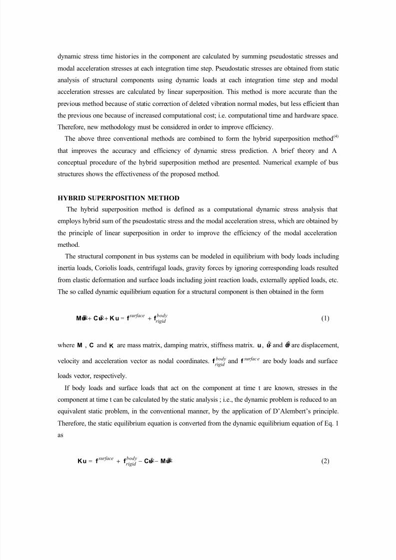
INTRODUCTION
In structural component design of bus systems, the appropriate criterion for fatigue failure should
be based on consideration of failure modes of the specific component being designed. If the structural
component is to withstand millions of cycles of load application, a criterion for fatigue failure must be
used. The fatigue damage caused by repeated dynamic loads depends on the number of cycles and the
frequency of the occurrence of significant stresses. Therefore, for accurate prediction of fatigue failure
in structural components, accurate prediction of dynamic stress time histories is required.
Experimental testing method may be the most exact for evaluation of dynamic stresses or strains in
components of bus systems. The experimental method, however, requires at least one prototype bus
system. The structural components in the prototype are then subjected to laboratory durability tests or
real vehicle durability tests on proving grounds or fields in which the loading life cycle is applied at an
accelerated rate.
Owing to growth in the power of digital computers, several analytical approaches for dynamic
stress calculation in structural components have been developed to speed design cycles. One method is
Quasi-static Method combined with Rigid Multibody Dynamic Simulation(1)
. In this method, a bus
system simulated by modeling its components as rigid bodies. From the rigid multibody dynamic
simulation of bus systems, loads in joints and D’Alembert acceleration loads on structural components
of concern are generated. These loads are applied the finite element models of structural components,
so that quasi-static stress time histories that used for dynamic stress time histories may be computed.
However, it does not consider the flexibility of structural components and the effects of such flexibility
on dynamically induced loads, such as joint reaction loads and inertia loads. Therefore, this methodmay be useful for very stiff systems but inaccurate for flexible systems
To consider flexibility effects in dynamic stress calculation, another method can be used ; i.e., Mode
Superposition Method combined with Flexible Multibody Dynamic Simulation(2),(3)
. In this method,
instead of full nodal coordinates, a few component modes are used to represent the deformation field
in each structural component for flexible multibody dynamic analysis. Dynamic stress time histories in
the structural component are then calculated by linear superposition of modal stresses, multiplied by
corresponding modal coordinate time histories that are generated from flexible multibody dynamic
analysis of the bus systems. When the modal stress superposition method are used for stress
calculation, accuracy of stress is dependent on the components modes that are used in flexible
multibody dynamic analysis. This means that inappropriate modes are selected, the resulting stresses
will be inaccurate. Therefore, this method must consider the selection of component modes in order to
improve accuracy.
To improve the accuracy of dynamic stress calculation, the other method can be used ; i.e., Mode
Acceleration Method combined with Flexible Multibody Dynamic Simulation(4)
. In this method,
8/16/2019 Dynamic Stress Analysis of a Bus Systems
http://slidepdf.com/reader/full/dynamic-stress-analysis-of-a-bus-systems 3/10
dynamic stress time histories in the component are calculated by summing pseudostatic stresses and
modal acceleration stresses at each integration time step. Pseudostatic stresses are obtained from static
analysis of structural components using dynamic loads at each integration time step and modal
acceleration stresses are calculated by linear superposition. This method is more accurate than the
previous method because of static correction of deleted vibration normal modes, but less efficient than
the previous one because of increased computational cost; i.e. computational time and hardware space.
Therefore, new methodology must be considered in order to improve efficiency.
The above three conventional methods are combined to form the hybrid superposition method(4)
that improves the accuracy and efficiency of dynamic stress prediction. A brief theory and A
conceptual procedure of the hybrid superposition method are presented. Numerical example of bus
structures shows the effectiveness of the proposed method.
HYBRID SUPERPOSITION METHOD
The hybrid superposition method is defined as a computational dynamic stress analysis that
employs hybrid sum of the pseudostatic stress and the modal acceleration stress, which are obtained by
the principle of linear superposition in order to improve the efficiency of the modal acceleration
method.
The structural component in bus systems can be modeled in equilibrium with body loads including
inertia loads, Coriolis loads, centrifugal loads, gravity forces by ignoring corresponding loads resulted
from elastic deformation and surface loads including joint reaction loads, externally applied loads, etc.
The so called dynamic equilibrium equation for a structural component is then obtained in the form
bodyrigid
surfacef f uKuCuM +=++ &&& (1)
where M , C and K are mass matrix, damping matrix, stiffness matrix. u , u and u& are displacement,
velocity and acceleration vector as nodal coordinates. bodyrigid
f and surfacef are body loads and surface
loads vector, respectively.
If body loads and surface loads that act on the component at time t are known, stresses in the
component at time t can be calculated by the static analysis ; i.e., the dynamic problem is reduced to an
equivalent static problem, in the conventional manner, by the application of D’Alembert’s principle.
Therefore, the static equilibrium equation is converted from the dynamic equilibrium equation of Eq. 1
as
uMuCf f uK &&&−−+= bodyrigid
surface (2)
8/16/2019 Dynamic Stress Analysis of a Bus Systems
http://slidepdf.com/reader/full/dynamic-stress-analysis-of-a-bus-systems 4/10
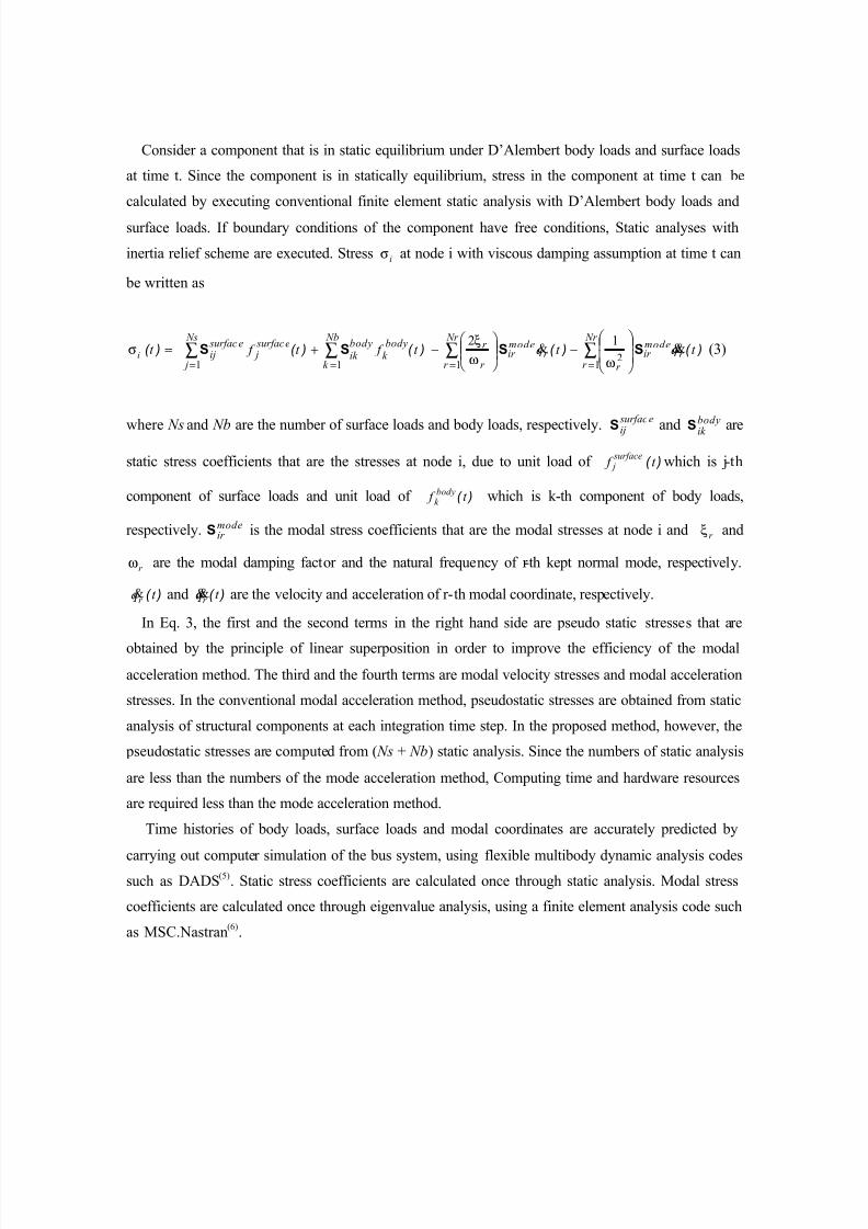
Consider a component that is in static equilibrium under D’Alembert body loads and surface loads
at time t. Since the component is in statically equilibrium, stress in the component at time t can be
calculated by executing conventional finite element static analysis with D’Alembert body loads and
surface loads. If boundary conditions of the component have free conditions, Static analyses with
inertia relief scheme are executed. Stress iσ at node i with viscous damping assumption at time t can
be written as
)( t iσ ∑∑∑∑====
−
−+=
Nr
r r
modeir
r
Nr
r r
modeir
r
r Nb
k
bodyk
bodyik
Ns
j
surface j
surfaceij t qt qt f t f
12
111
12 )( )( )( )( &&& SSSS
ωω
ξ (3)
where Ns and Nb are the number of surface loads and body loads, respectively.
surface
ijS and
body
ik S are
static stress coefficients that are the stresses at node i, due to unit load of )( t f surface j which is j-th
component of surface loads and unit load of )( t f bodyk which is k-th component of body loads,
respectively. modeir S is the modal stress coefficients that are the modal stresses at node i and r ξ and
r ω are the modal damping factor and the natural frequency of r-th kept normal mode, respectively.
)( t qr & and )( t qr
&& are the velocity and acceleration of r-th modal coordinate, respectively.
In Eq. 3, the first and the second terms in the right hand side are pseudo static stresses that are
obtained by the principle of linear superposition in order to improve the efficiency of the modal
acceleration method. The third and the fourth terms are modal velocity stresses and modal acceleration
stresses. In the conventional modal acceleration method, pseudostatic stresses are obtained from static
analysis of structural components at each integration time step. In the proposed method, however, the
pseudostatic stresses are computed from ( Ns + Nb) static analysis. Since the numbers of static analysis
are less than the numbers of the mode acceleration method, Computing time and hardware resources
are required less than the mode acceleration method.
Time histories of body loads, surface loads and modal coordinates are accurately predicted by
carrying out computer simulation of the bus system, using flexible multibody dynamic analysis codessuch as DADS
(5). Static stress coefficients are calculated once through static analysis. Modal stress
coefficients are calculated once through eigenvalue analysis, using a finite element analysis code such
as MSC.Nastran(6)
.
8/16/2019 Dynamic Stress Analysis of a Bus Systems
http://slidepdf.com/reader/full/dynamic-stress-analysis-of-a-bus-systems 5/10
IMPLEMENTATION
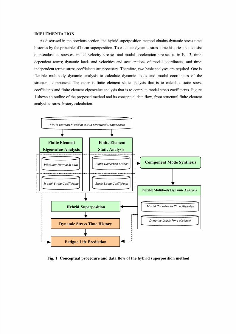
As discussed in the previous section, the hybrid superposition method obtains dynamic stress time
histories by the principle of linear superposition. To calculate dynamic stress time histories that consist
of pseudostatic stresses, modal velocity stresses and modal acceleration stresses as in Eq. 3, time
dependent terms; dynamic loads and velocities and accelerations of modal coordinates, and time
independent terms; stress coefficients are necessary. Therefore, two basic analyses are required. One is
flexible multibody dynamic analysis to calculate dynamic loads and modal coordinates of the
structural component. The other is finite element static analysis that is to calculate static stress
coefficients and finite element eigenvalue analysis that is to compute modal stress coefficients. Figure
1 shows an outline of the proposed method and its conceptual data flow, from structural finite element
analysis to stress history calculation.
Fig. 1 Conceptual procedure and data flow of the hybrid superposition method
Flexible Multibody Dynamic Analysis
Finite Element
Eigenvalue Analysis
Finite Element
Static Analysis
Static Stress Coeff icients Modal Stress Coeff icients
Vibration Normal M odes Static Correction Modes
Hybrid Superposition
F ini te Element M odel of a Bus Structural Components
Modal Coordinates Time Histories
Dynamic Loads Time Histori e
Component Mode Synthesis
Fatigue Life Prediction
Dynamic Stress Time History
8/16/2019 Dynamic Stress Analysis of a Bus Systems
http://slidepdf.com/reader/full/dynamic-stress-analysis-of-a-bus-systems 6/10
Using existing flexible multibody dynamic and finite element analysis codes such as DADS and
MSC.Nastran, the hybrid superposition method can be implemented as follows.
Step 1. For flexible multibody dynamic analysis, component deformation modes must be selected for
flexible bodies in the bus system that may require finite element vibration and static analysis
using finite element analysis codes. In flexible multibody dynamic analysis, the sub-structuring
technique may be used, if critical region can be modeled as a separated body from the
remaining structure.
Step 2. Using flexible multibody dynamic analysis code, the bus system of interest is simulated under
the specified scenario to obtain dynamic load time histories applying on each structural
component and modal coordinate time histories of each component.
Step 3. To calculated static stress coefficients in Eq. 3, finite element static analysis is carried out
through applying each unit load at the finite element node points where corresponding dynamic
load is applied. To calculate modal stress coefficients in Eq. 3, finite element eigenvalue
analysis is carried out. For a finite element model that is high dimensional, the conventional
sub-structuring technique may be used to calculate stress coefficients in local area.
Step 5. As in Eq. 3, static stress influence coefficients that are obtained in step 3 are multiplied by
corresponding to magnitudes of dynamic load time histories from step 2. Modal stress
influence coefficients that are obtained in step 4 are multiplied by corresponding to magnitudes
of modal coordinates time histories from step 2. Performing the multiplication and summation
at each integration time step yields dynamic stress time histories at every time step.Step 6. Finally, fatigue lives of structural components are predicted by use of dynamic stress time
histories from step 2 or hybrid superposition of results from step 2 and step 3.
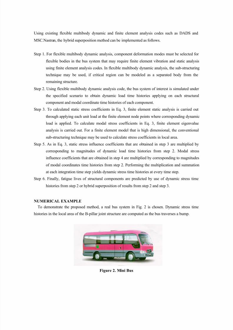
NUMERICAL EXAMPLE
To demonstrate the proposed method, a real bus system in Fig. 2 is chosen. Dynamic stress time
histories in the local area of the B-pillar joint structure are computed as the bus traverses a bump.
Figure 2. Mini Bus

8/16/2019 Dynamic Stress Analysis of a Bus Systems
http://slidepdf.com/reader/full/dynamic-stress-analysis-of-a-bus-systems 7/10
For dynamic simulations, The multibody model of the bus systems is modeled as in Fig. 3. To include
nonlinear effects of leaf springs and shock absorbers, bump stoppers, stabilizer bars and bushes in the
suspension system, nonlinear properties measured from component experiments are used. Mechanical
parts, such as engine, air conditioner and other nonstructural mass elements are lumped to nodes of the
body structure with spring and damper elements.
(a) Total system (b) Chassis
Figure 3. Multibody model of the bus systems
To consider the flexibility effect of the body structure, it is modeled as a flexible body. The
MSC.Nastran code is employed for eigenvalue and static analyses with free boundary conditions to
compute component modes. Component modes for the body structure are chosen as combination of
four vibration normal modes in Fig. 4 and eight static correction modes; i.e. residual inertia relief
attachment modes(3),(7)
. Static correction modes are defined at the joints between body structure andleaf springs.
(a) Torsion (b) Lateral Bending (c) Vertical Bending
Figure 4. Vibration normal modes
The flexible multibody dynamic simulations are carried out by using DADS code with the scenario
which the bus traverse a sinusoidal bump in Fig. 5 with a constant forward speed of 15km/hour.
The A-point in the B-pillar joint connected the waist rail in Fig. 6 is the crit ical area where a few
durability problems have occurred. When the bus traverses over the bump, large dynamic stresses are
anticipated in the joint.
8/16/2019 Dynamic Stress Analysis of a Bus Systems
http://slidepdf.com/reader/full/dynamic-stress-analysis-of-a-bus-systems 8/10
-10.50 -10.00 -9.50 -9.00 -8.50 -8.00 -7.50
Distance (m)
-1.00
-0.75
-0.50
-0.25
0.00
H e i g h t ( m )
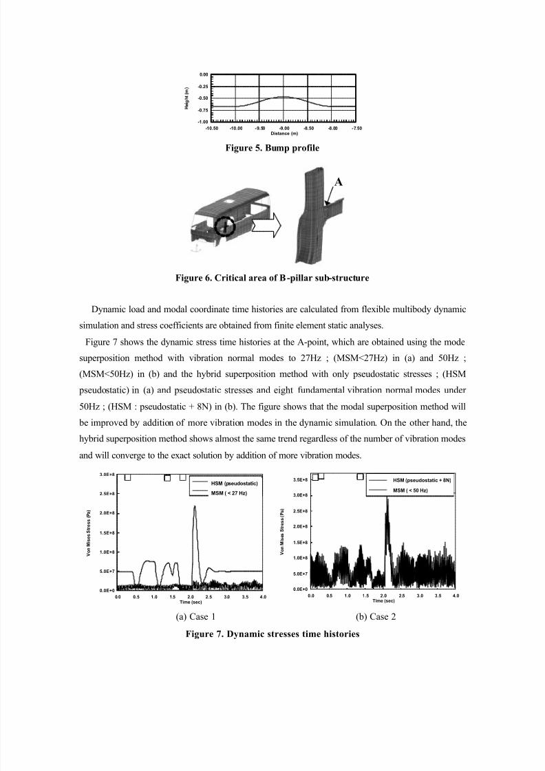
Figure 5. Bump profile
Figure 6. Critical area of B-pillar sub-structure
Dynamic load and modal coordinate time histories are calculated from flexible multibody dynamic
simulation and stress coefficients are obtained from finite element static analyses.
Figure 7 shows the dynamic stress time histories at the A-point, which are obtained using the mode
superposition method with vibration normal modes to 27Hz ; (MSM<27Hz) in (a) and 50Hz ;
(MSM<50Hz) in (b) and the hybrid superposition method with only pseudostatic stresses ; (HSM
pseudostatic) in (a) and pseudostatic stresses and eight fundamental vibration normal modes under
50Hz ; (HSM : pseudostatic + 8N) in (b). The figure shows that the modal superposition method will
be improved by addition of more vibration modes in the dynamic simulation. On the other hand, the
hybrid superposition method shows almost the same trend regardless of the number of vibration modes
and will converge to the exact solution by addition of more vibration modes.
(a) Case 1 (b) Case 2
Figure 7. Dynamic stresses time histories
0.0 0.5 1.0 1.5 2.0 2.5 3.0 3.5 4.0Time (sec)
0.0E+0
5.0E+7
1.0E+8
1.5E+8
2.0E+8
2.5E+8
3.0E+8
V o n M i s
e s S t r e s s ( P a )
MMAM (pseudostatic)
MDM (27Hz)
HSM (pseudostatic)
MSM ( < 27 Hz)
A
0.0 0.5 1.0 1.5 2.0 2.5 3.0 3.5 4.0Time (sec)
0.0E+0
5.0E+7
1.0E+8
1.5E+8
2.0E+8
2.5E+8
3.0E+8
3.5E+8
V o n M i s e s S t r e s s ( P a )
HSSM (pseudostatic + 8n)
MMAM (50Hz)
HSM (pseudostatic + 8N)
MSM ( < 50 Hz)

8/16/2019 Dynamic Stress Analysis of a Bus Systems
http://slidepdf.com/reader/full/dynamic-stress-analysis-of-a-bus-systems 9/10
Fig. 8 shows FFT(Fast Fourier Transformation) of dynamic stress time histories in terms of
frequencies, which are obtained using the mode acceleration method with vibration normal modes to
50Hz ; (MAM<50Hz) and the hybrid superposition method with pseudostatic stresses and eight
fundamental vibration normal modes under 50Hz ; (HSM : pseudostatic + 8N). The figure shows that
FFT of the hybrid superposition method are similar to that of the modal acceleration method. Using
SGI Indigo R10000 engineering workstation, total solving time and hardware space of the hybrid
superposition method, however, required 970.7 sec and 7.2 GB, respectively. On the other hand, them
of the modal acceleration method required 2223.6 sec and 12.5 GB.
0.0 10.0 20.0 30.0 40.0 50.0Frequency (Hz )
1.0E+4
1.0E+5
1.0E+6
1.0E+7
1.0E+8
A m p l i t u d e o f V o n M i s e s S t r e s s
HSM (pseudostatic + 8N)
MAM ( < 50 Hz)
Figure 8. Fast Fourier Transform of dynamic stress time histories
These imply that the hybrid superposition method is more accurate than the mode superposition
method and more efficient than the mode acceleration method. This figure clearly shows
improvements of the proposed method over the conventional methods in the computation of the
dynamic stress time histories in structural components of bus systems and the other mechanical
systems.
CONCLUSION
In this paper, the hybrid superposition method is compared with the conventional methods; i.e. the
mode superposition method and the mode acceleration method. In the mode superposition method,
stress can be computed only when vibration normal modes are defined for the component. Thus, if the
component is very stiff and is modeled as a rigid body, zero stresses will be obtained. Even for flexible
bodies, the accuracy of stress that obtained will depend on the selection of vibration normal modes. In
the hybrid superposition method, however, dynamic loads that are accurately predicted in flexible
multibody dynamic simulation are used in stress calculation, hence avoiding the dependence on
vibration normal modes. In the mode acceleration method, pseudostatic stresses are computed from a
8/16/2019 Dynamic Stress Analysis of a Bus Systems
http://slidepdf.com/reader/full/dynamic-stress-analysis-of-a-bus-systems 10/10
great number of static analyses, where the number of static analyses is equal to the number of total
integration time steps. In the hybrid superposition method, however, the pseudostatic stresses are
computed from a small number of static analyses, where the number of static analyses is equal to that
of total dynamic loads, so that computing time and hardware resources are required less than the mode
acceleration method. Therefore the hybrid superposition method is more accurate than the mode
superposition method and more efficient than the mode acceleration method.
REFERENCE
1. Winfrey, R. C., “Elastic Link Mechanism Dynamics,” Transaction of ASME, Journal of Engineering
for industry, Vol. 93, N0. 1, pp. 268-272, Feb. 1971.
2. Liu, T. S., “Computational Methods for Life Prediction of Mechanical Components of Dynamic
Systems,” Ph. D. Thesis, The Univ. of Iowa, 1987.
3. Yoo. W. S., and Haug, E. J., “Dynamics of Articulated Structures. Part I : Theory,” Journal of
Structural Mechanics, Vol. 14, No. 1, pp. 105-126, 1986.
4. Kim, H. S., “Dynamic Stress Analysis of a Flexible Body in Multibody System for Fatigue Life
Prediction,” Ph.D. Thesis, Inha University, Incheon, Korea, 1999.
5. DADS User’s Manual , Rev. 8.0, Computer Aided Design Software, Inc., IA 5221, 1995.
6. MSC/NASTRAN User’s Manual, Ver. 70, The MacNeal-Schwendler Corporation, June 1997.
7. Craig. R. R., and Chang, C. J., “On the Use of Attachment Modes in Substructure Coupling for
Dynamic Analysis,” Dynamic & Structural Dynamics, AIAA/ASME 18th Structures, Structural
Dynamics & Material Conference.