Embed Size (px)
Citation preview

LABORATORY MANUAL
Dynamics of Machines
(ME 506)
Department of Mechanical Engineering
Jorhat Engineering College
Jorhat – 785007 (Assam)

(ii)
COLLEGE VISION AND MISSION
Vision:
To develop human resources for sustainable industrial and societal growth
through excellence in technical education and research.
Mission:
1. To impart quality technical education at UG, PG and PhD levels through good
academic support facilities.
2. To provide an environment conducive to innovation and creativity, group work and
entrepreneurial leadership.
3. To develop a system for effective interactions among industries, academia, alumni
and other stakeholders.
4. To provide a platform for need-based research with special focus on regional
development.
DEPARTMENT VISION AND MISSION
Vision:
To emerge as a centre of excellence in mechanical engineering and maintain it
through continuous effective teaching-learning process and need-based research.
Mission:
M1: To adopt effective teaching-learning processes to build students capacity and
enhance their skills.
M2: To nurture the students to adapt to the changing needs in academic and industrial
aspirations.
M3: To develop professionals to meet industrial and societal challenges.
M4: To motivate students for entrepreneurial ventures for nation-building.

(iii)
Program Outcomes (POs)
Engineering graduates will be able to:
1. Engineering knowledge: Apply the knowledge of mathematics, science, engineering
fundamentals, and an engineering specialization to the solution of complex
engineering problems.
2. Problem analysis: Identify, formulate, review research literature, and analyze
complex engineering problems reaching substantiated conclusions using first
principles of mathematics, natural sciences, and engineering sciences.
3. Design/development of solutions: Design solutions for complex engineering
problems and design system components or processes that meet the specified needs
with appropriate consideration for the public health and safety, and the cultural,
societal, and environmental considerations.
4. Conduct investigations of complex problems: Use research-based knowledge and
research methods including design of experiments, analysis and interpretation of data,
and synthesis of the information to provide valid conclusions.
5. Modern tool usage: Create, select, and apply appropriate techniques, resources, and
modern engineering and IT tools including prediction and modelling to complex
engineering activities with an understanding of the limitations.
6. The engineer and society: Apply reasoning informed by the contextual knowledge to
assess societal, health, safety, legal and cultural issues and the consequent
responsibilities relevant to the professional engineering practice.
7. Environment and sustainability: Understand the impact of the professional
engineering solutions in societal and environmental contexts, and demonstrate the
knowledge of, and need for sustainable development.
8. Ethics: Apply ethical principles and commit to professional ethics and responsibilities
and norms of the engineering practice.
9. Individual and team work: Function effectively as an individual, and as a member
or leader in diverse teams, and in multidisciplinary settings.
10. Communication: Communicate effectively on complex engineering activities with
the engineering community and with society at large, such as, being able to
comprehend and write effective reports and design documentation, make effective
presentations, and give and receive clear instructions.
11. Project management and finance: Demonstrate knowledge and understanding of the
engineering and management principles and apply these to one’s own work, as a
member and leader in a team, to manage projects and in multidisciplinary
environments.
12. Life-long learning: Recognize the need for, and have the preparation and ability to
engage in independent and life-long learning in the broadest context of technological
change.
(iv)
Programme Educational Objectives (PEOs)
The Programme Educational Objectives of Department of Mechanical Engineering are given
below:
PEO1: Gain basic domain knowledge, expertise and self-confidence for employment,
advanced studies, R&D, entrepreneurial ventures activities, and facing
challenges in professional life.
PEO2: Develop, improve and maintain effective domain based systems, tools and
techniques that socioeconomically feasible and acceptable and transfer those
technologies/developments for improving quality of life.
PEO3: Demonstrate professionalism through effective communication skill, ethical
and societal commitment, team spirit, leadership quality and get involved in
life-long learning to realize career and organisational goal and participate in
nation building.
Program Specific Outcomes (PSOs)
The programme specific outcomes of Department of Mechanical Engineering are given
below:
PSO1: Capable to establish a career in Mechanical and interdisciplinary areas with
the commitment to the society and the nation.
PSO2: Graduates will be armed with engineering principles, analysing tools and
techniques and creative ideas to analyse, interpret and improve mechanical
engineering systems.
Course Outcomes (COs)
At the end of the course, the student will be able to:
CO1 Measure radius of gyration, moment of inertia for different components.
CO2 Analyse the dynamic behaviour of the machine elements/ components like
Gyroscope and vibration parameters.
Mapping of COs with POs:
COs PO1 PO2 PO3 PO4 PO5 PO6 PO7 PO8 PO9 PO10 PO11 PO12 PSO1 PSO2
CO1 2 2 2 1 1 1
CO2 2 2 2 1 1 1

(v)
STUDENT PROFILE
NAME :
ROLL NUMBER :
SECTION :
SEMESTER : 5th Semester
YEAR :
PERFORMANCE RECORD
EXP.
NO. TITLE OF EXPERIMENT
REMARKS /
GRADE
1 Compound Pendulum Apparatus.
2 Study of Longitudinal Vibration of Helical Spring.
3 Torsional Pendulum (without damping).
4 Torsional Pendulum (with damping).
5 Gyroscopic Couple.
OFFICE USE
Checked By :
Overall Grade / Marks :
Signature of Teacher :
(1)
Jorhat Engineering College Dynamics of Machines Lab
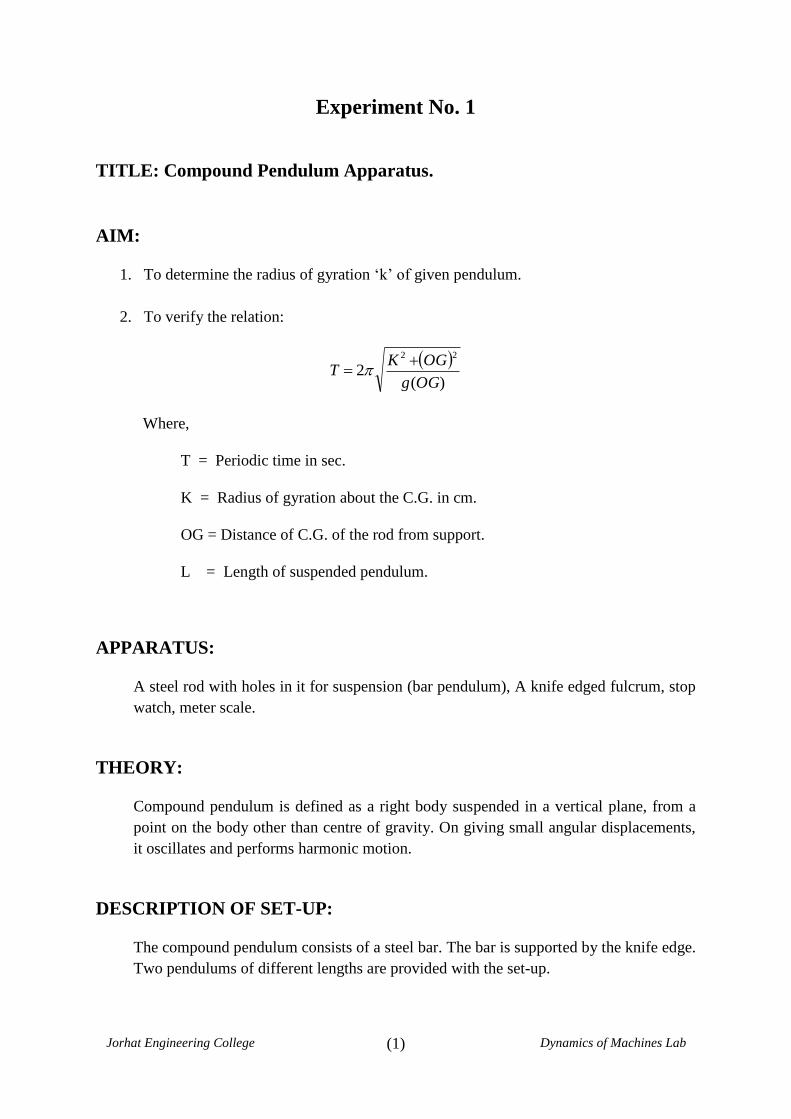
Experiment No. 1
TITLE: Compound Pendulum Apparatus.
AIM:
1. To determine the radius of gyration ‘k’ of given pendulum.
2. To verify the relation:
)(
222
OGg
OGKT
Where,
T = Periodic time in sec.
K = Radius of gyration about the C.G. in cm.
OG = Distance of C.G. of the rod from support.
L = Length of suspended pendulum.
APPARATUS:
A steel rod with holes in it for suspension (bar pendulum), A knife edged fulcrum, stop
watch, meter scale.
THEORY:
Compound pendulum is defined as a right body suspended in a vertical plane, from a
point on the body other than centre of gravity. On giving small angular displacements,
it oscillates and performs harmonic motion.
DESCRIPTION OF SET-UP:
The compound pendulum consists of a steel bar. The bar is supported by the knife edge.
Two pendulums of different lengths are provided with the set-up.

(2)
Jorhat Engineering College Dynamics of Machines Lab
PROCEDURE:
1. Support the rod on knife edge.
2. Note the length of suspended pendulum and determine OG.
3. Allow the bar to oscillate and determine T by knowing the time for say 10
oscillations.
4. Repeat the experiment with different length of suspension.
5. Complete the observation table given below.
OBSERVATION TABLE:
Sl.
No.
L
(cm) OG
No. of
Osc.
(N)
Time or Osc. T Expt.=n/t K Expt. K Theoretical
1 57.2 28.5 10 12.3 1.23 16.13 16.51
2
3
CALCULATIONS:
Length of suspended pendulum L = 57.2 cm
Width of suspended pendulum b = 2.0cm
Find k experimental from relation:
12
22 bLk Exp
or
)(
222
OGg
OGKT
Substituting for OG and T in above formula find k Experimental.
32
LkTh
Compare values of k obtained theoretical and experimental.
(3)
Jorhat Engineering College Dynamics of Machines Lab
REMARKS:
Exp. No. 1 Title: Compound Pendulum Apparatus.
Name of Student:
Roll No.:
Date of Experiment:
Date of Submission:
Signature of Teacher SEAL
with Date of Check
(4)
Jorhat Engineering College Dynamics of Machines Lab
Experiment No. 2
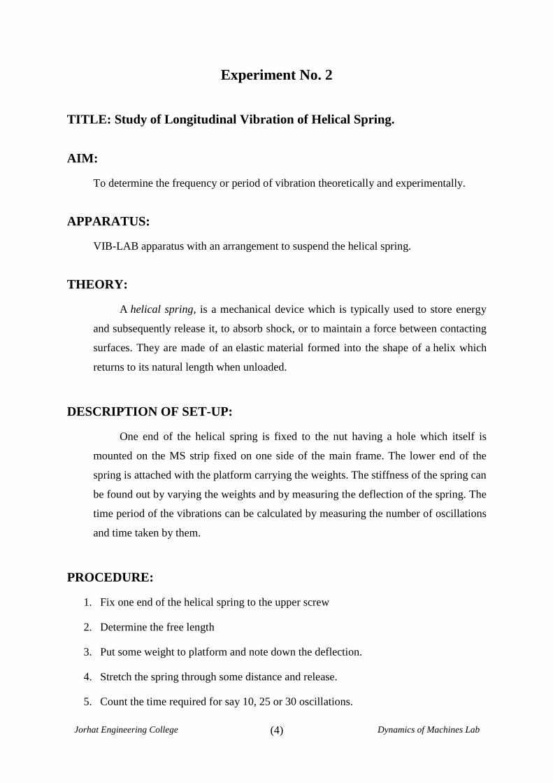
TITLE: Study of Longitudinal Vibration of Helical Spring.
AIM:
To determine the frequency or period of vibration theoretically and experimentally.
APPARATUS:
VIB-LAB apparatus with an arrangement to suspend the helical spring.
THEORY:
A helical spring, is a mechanical device which is typically used to store energy
and subsequently release it, to absorb shock, or to maintain a force between contacting
surfaces. They are made of an elastic material formed into the shape of a helix which
returns to its natural length when unloaded.
DESCRIPTION OF SET-UP:
One end of the helical spring is fixed to the nut having a hole which itself is
mounted on the MS strip fixed on one side of the main frame. The lower end of the
spring is attached with the platform carrying the weights. The stiffness of the spring can
be found out by varying the weights and by measuring the deflection of the spring. The
time period of the vibrations can be calculated by measuring the number of oscillations
and time taken by them.
PROCEDURE:
1. Fix one end of the helical spring to the upper screw
2. Determine the free length
3. Put some weight to platform and note down the deflection.
4. Stretch the spring through some distance and release.
5. Count the time required for say 10, 25 or 30 oscillations.

(5)
Jorhat Engineering College Dynamics of Machines Lab
6. Determine the actual time period.
7. Repeat the experiment for different weights.
FORMULA USED:
For theoretical value: Tt = 2Π δe
g
For experimental value: Te =2Π
ωn
Where, 𝛿𝑒 = Deflection of spring after giving load.
OBSERVATION TABLE – I
Sl.
No.
Weight
attached
W in gm.
Deflection of
spring after
giving load 𝛿𝑒
in cm
Theoretical time
period 𝑇𝑒 in
second
Average theoretical
time period 𝑇𝑡 (in second)
Theoretical
frequency
𝑓𝑡 = 1 𝑇𝑡
1
2
3
OBSERVATION TABLE: II
Sl.
No.
Weight
attached
W in gm.
No. of
Oscillations
(n)
Time
required for
𝑛 oscillation
(𝑡) in second
Time
period
𝑇 = 𝑡 𝑛
Average
experimental
time period
𝑇𝑒 (in second)
Experimental
frequency
𝑓𝑒 = 1 𝑇𝑒
1
2
3

(6)
Jorhat Engineering College Dynamics of Machines Lab
RESULTS:
% variation of theoretical frequency = 𝑓𝑡 − 𝑓𝑒 𝑓𝑡 × 100% =
REMARKS:
Exp. No. 2 Title: Study of Longitudinal Vibration of Helical Spring.
Name of Student:
Roll No.:
Date of Experiment:
Date of Submission:
Signature of Teacher SEAL
with Date of Check

(7)
Jorhat Engineering College Dynamics of Machines Lab
Experiment No. 3
TITLE: Torsional Pendulum (without damping).
OBJECTIVE:
To determine the mass moment of inertia of a circular disc and compare it with the
calculated value.
APPARATUS:
1. Experimental circular disc as a torsional pendulum.
2. Micrometer, scale and stop watch.
PROCEDURE:
1. Measure the diameter of rod (𝑑), radius of the disc (𝑅) and weight of the disc.
2. Give a small angular rotation to the disc and count the number of oscillation and the
time required for it which will give the value of the frequency (𝑓).
3. Assume that the vibration is purely torsional and there is no bending of the rod while
displacing the disc.
4. Repeat it for three observations and tabulate the results.
FORMULA USED:
For experimental value: Ie =C. d4
128πLf 2
For theoretical value: Ie =W. R2
2gc
Where,
𝐶 = Modulus of rigidity for the shaft material = 0.8 × 10⁶ kg cm
𝑑 = Diameter of the rod cm
𝑓 = Frequency in Cycles/second
𝑊 = Weight of the disc = 9.389 kg
𝑅 = Radius of the disc.

(8)
Jorhat Engineering College Dynamics of Machines Lab
OBSERVATION TABLE:
Sl.
No.
No. of
oscillations
Time
required
for it
(𝑠𝑒𝑐)
Frequency
(𝑓)
𝑐𝑦𝑐𝑙𝑒𝑠/𝑠𝑒𝑐
Mass MOI
𝐼𝑒
Average
Mass MOI
𝐼𝑒
Theoretical
Mass MOI
𝐼𝑡
REMARKS:

(9)
Jorhat Engineering College Dynamics of Machines Lab
Exp. No. 3 Title: Torsional Pendulum (without damping).
Name of Student:
Roll No.:
Date of Experiment:
Date of Submission:
Signature of Teacher SEAL
with Date of Check
(10)
Jorhat Engineering College Dynamics of Machines Lab
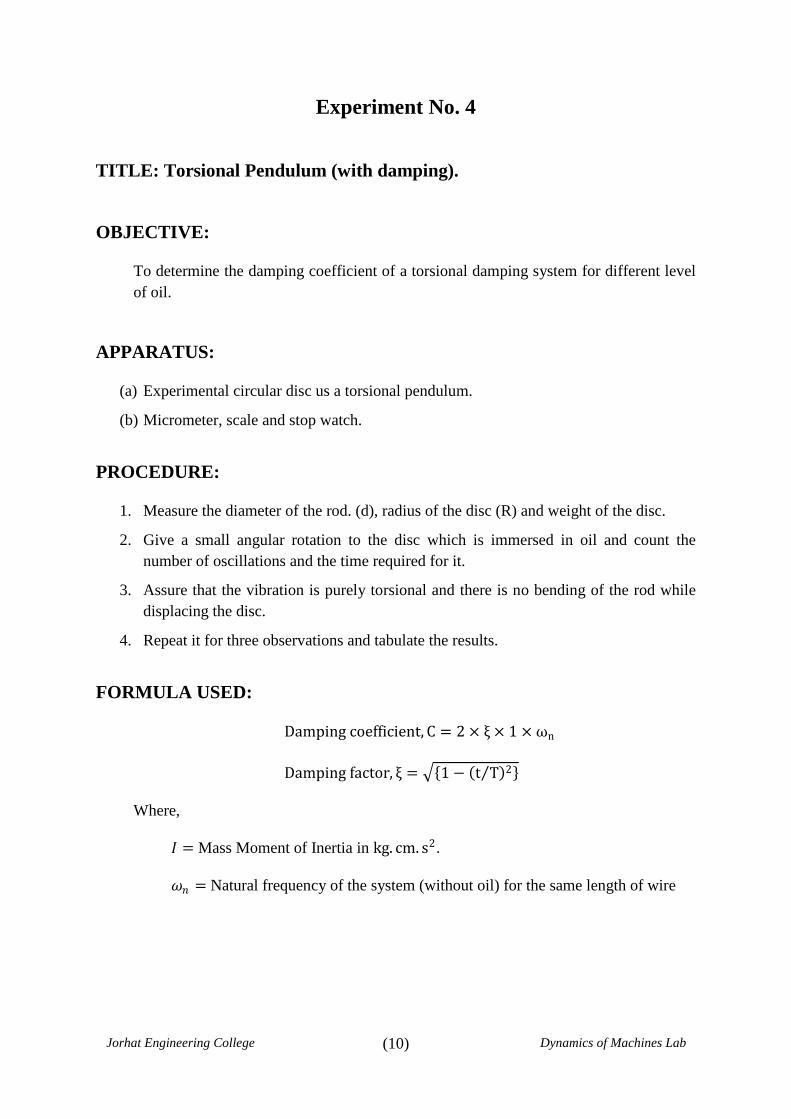
Experiment No. 4
TITLE: Torsional Pendulum (with damping).
OBJECTIVE:
To determine the damping coefficient of a torsional damping system for different level
of oil.
APPARATUS:
(a) Experimental circular disc us a torsional pendulum.
(b) Micrometer, scale and stop watch.
PROCEDURE:
1. Measure the diameter of the rod. (d), radius of the disc (R) and weight of the disc.
2. Give a small angular rotation to the disc which is immersed in oil and count the
number of oscillations and the time required for it.
3. Assure that the vibration is purely torsional and there is no bending of the rod while
displacing the disc.
4. Repeat it for three observations and tabulate the results.
FORMULA USED:
Damping coefficient, C = 2 × ξ × 1 ×ωn
Damping factor, ξ = 1− t T 2
Where,
𝐼 = Mass Moment of Inertia in kg. cm. s2.
𝜔𝑛 = Natural frequency of the system (without oil) for the same length of wire
(11)
Jorhat Engineering College Dynamics of Machines Lab
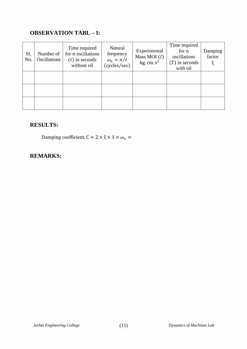
OBSERVATION TABL – I:
Sl.
No.
Number of
Oscillations
Time required
for 𝑛 oscillations
(𝑡) in seconds
without oil
Natural
frequency
𝜔𝑛 = 𝑛 𝑡 cycles sec
Experimental
Mass MOI (𝐼)
kg. cm. s2
Time required
for 𝑛
oscillations
(𝑇) in seconds
with oil
Damping
factor
ξ
RESULTS:
Damping coefficient, C = 2 × ξ × 1 ×ωn =
REMARKS:
(12)
Jorhat Engineering College Dynamics of Machines Lab
Exp. No. 4 Title: Torsional Pendulum (with damping).
Name of Student:
Roll No.:
Date of Experiment:
Date of Submission:
Signature of Teacher SEAL
with Date of Check

(13)
Jorhat Engineering College Dynamics of Machines Lab
Experiment No. 5
TITLE: Gyroscopic Couple.
OBJECTIVE:
To determine percentage variation of theoretical and experimental variation of
gyroscopic couple
APPARATUS:
1. Motorized Gyroscope with a speed control arrangement.
2. Tachometer.
SPECIFICATION OF THE APPARATUS:
1. Mass Moment of Inertia of the spinning disc, I = 0.800 kg.cm2
2. Distance of bolt centre of weight pan from disc centre, h = 20.8 cm.
3. Motor = 0.25 hp, single phase, 4000 rpm, 50 Hz, with autotransformer provided for
speed regulation.
PROCEDURE:
1. Balance the rotor position on the horizontal frame.
2. Start the motor by increasing the voltage with the autotransformer and wait till the
motor attains a second speed.
3. Put the weights W = 1 kg, 2 kg or 5 kg on the weight pan and start the stop watch to
note time in second required for precession.
4. The speed of spin is measured by tachometer.
5. Compute the gyroscopic couple.
6. Compare the couple applied by the weights and find the percentage variation.

(14)
Jorhat Engineering College Dynamics of Machines Lab
FORMULA USED:
Experimental gyroscopic couple, Ce = I𝜔𝜔𝑝max
Maximum angular velocity of precession ( in the forward
direction )
𝜔𝑝𝑓 = 𝜃𝑓𝑡𝑓 × 2𝜋 360° 𝑟𝑎𝑑/𝑠𝑒𝑐
Maximum angular velocity of precession ( in the backward
direction )
𝜔𝑝𝑟 = 𝜃𝑟𝑡𝑓 × 2𝜋 360° 𝑟𝑎𝑑/𝑠𝑒𝑐
Average angular velocity of precession 𝑤𝑝𝑎𝑣𝑔 = 𝜔𝑝𝑓 +
𝜔𝑝𝑟 /2 𝑟𝑎𝑑/𝑠𝑒𝑐
Maximum angular velocity of precession 𝜔𝑝𝑚𝑎𝑥 = 2 ×𝜔𝑝𝑎𝑣𝑔
Theoretical Gyroscopic couple, Ct = W× h
Observation Table:
Sl.
No. 𝝎
rad/s
W
kg
Forward
angle 𝜽f
in rad
Forward
time tf in
sec
𝝎pf
rad/sec
Backward
angle 𝜽r in
rad
Backward
time tr in
sec
𝝎pr rad/sec
𝝎max Gyroscopic
couple Ce
Theoretical
gyroscopic
couple Ct
%
variation

(15)
Jorhat Engineering College Dynamics of Machines Lab
REMARKS:
Exp. No. 5 Title: Gyroscopic Couple
Name of Student:
Roll No.:
Date of Experiment:
Date of Submission:
Signature of Teacher SEAL
with Date of Check