Embed Size (px)
Citation preview
Dynamics of Particles
2. Kinematics of Particles
Reference : Engineering Mechanics : Dynamics (J.L.Meriam, L.G.Kraige), 7th Edition, pp.77, P.2.161
Type of Analysis : Kinematics of Particles, Polar Coordinates
Type of Element : Particle (One part)
Comparison of results
Object Value Theory RecurDyn Error
�̇� [m/s] 3.58 3.575 0.005
�̈� [m/s2] 315 315.12 0.12
�̇� [rad/s] 17.88 17.86 0.02
�̈� [rad/ s2] -1510 -1510.43 0.43
Note
1. Theoretical Solution
1) Basic Conditions
β = 30°
�̇� = 60 𝑟𝑎𝑑/𝑠 = 𝑐𝑜𝑛𝑠𝑡
2) Geometrical Constraint
r ∙ cosθ + 90 ∙ cosβ = 300
r ∙ cosθ = 300 − 90 ∙ cosβ = 222.06
r ∙ sinθ = 90 ∙ sinβ = 45
r ∙ cosθ = 300 − 90 ∙ cosβ = 222.06
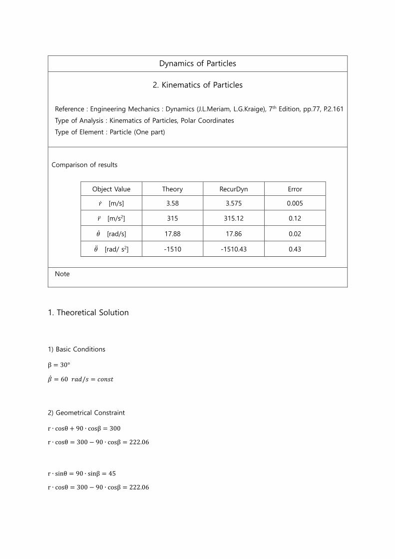
∴ tanθ =45
222.06 → θ = 11.46°
∴ r = 226.57
∴ γ = β + θ = 30 + 11.46 = 41.46°
3) Velocity and Acceleration of Point A of Link AC
𝑣 = 90 ∙ �̇� = 5400 𝑚𝑚/𝑠
𝑎 = 90 ∙ �̇�2 = 324 ∙ 103 𝑚𝑚2/𝑠
4) Calculate �̇�, �̈�, �̇�, �̈� with the Velocity and Acceleration
𝑣𝜃 = 𝑟�̇� = 𝑣 ∙ 𝑐𝑜𝑠𝛾 = 5400 ∙ 𝑐𝑜𝑠41.46 = 4046.86 𝑚𝑚/𝑠
�̇� =4046.86
226.57= 17.86 𝑟𝑎𝑑/𝑠
𝑣𝑟 = �̇� = 𝑣 ∙ 𝑠𝑖𝑛𝛾 = 5400 ∙ 𝑠𝑖𝑛41.46 = 3575.32 𝑚𝑚/𝑠
�̇� = 3575.32 𝑚𝑚/𝑠
𝑎𝑟 = �̈� − 𝑟�̇�2 = 𝑎 ∙ 𝑐𝑜𝑠𝛾
�̈� = 𝑟�̇�2 + 𝑎 ∙ 𝑐𝑜𝑠𝛾 = 226.57 ∙ 17.862 + 324 ∙ 103 ∙ 𝑐𝑜𝑠41.46 = 315,082.68 𝑚𝑚/𝑠2
𝑎𝜃 = 𝑟�̈� + 2�̇��̇� = −𝑎 ∙ 𝑠𝑖𝑛𝛾
�̈� =−𝑎 ∙ 𝑠𝑖𝑛𝛾 − 2�̇��̇�
𝑟=
(−324 ∙ 103 ∙ 𝑠𝑖𝑛41.46 − 2 ∙ 3575.32 ∙ 17.86)
226.57= −1,510.48 rad/𝑠2
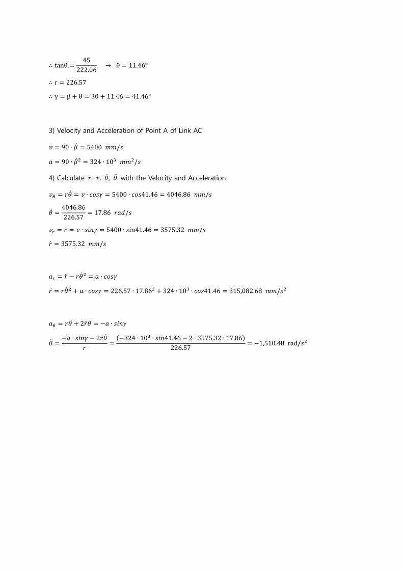
2. Numerical Solution – Using RecurDyn
1) Create New Model
- Set the model name : P2_161
- Set the “Unit” to “MMKS”
- Set the “Gravity” to “-Y”
2) Create an Object Shape
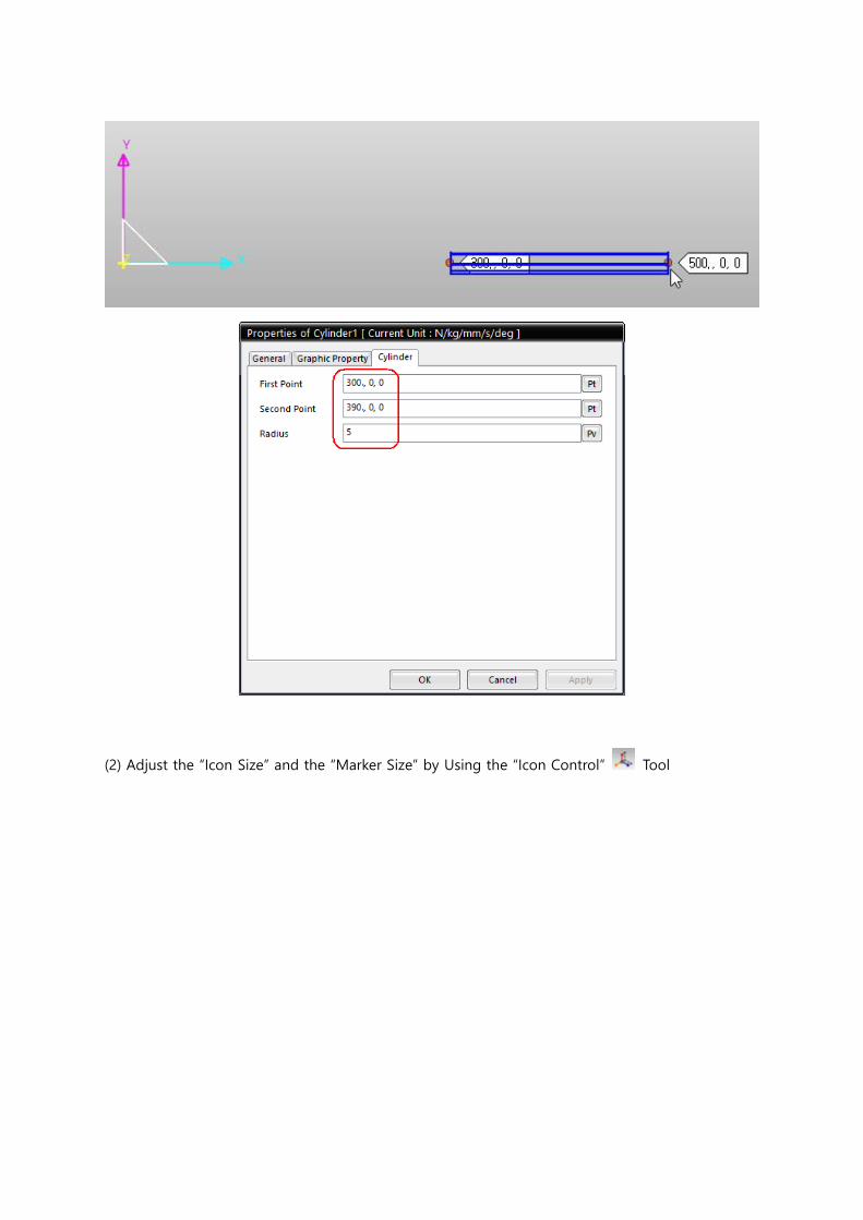
(1) Create a “Cylinder”, “Body1”
- Click the point (300, 0, 0) and the point (390, 0, 0) to create a cylinder with radius of 5mm.
- Double click “Body1” in the working window or select “Body1 – Edit” (Click the right button of
mouse after selecting “Body1” in the “Database” window, then, select “Edit” in the pop up box.)
in the “Database” window on the right to enter the “Body Edit” mode.
- Select “Cylinder1” in the “Database” window and select “Property” in the pop up box.
(2) Adjust the “Icon Size” and the “Marker Size” by Using the “Icon Control” Tool
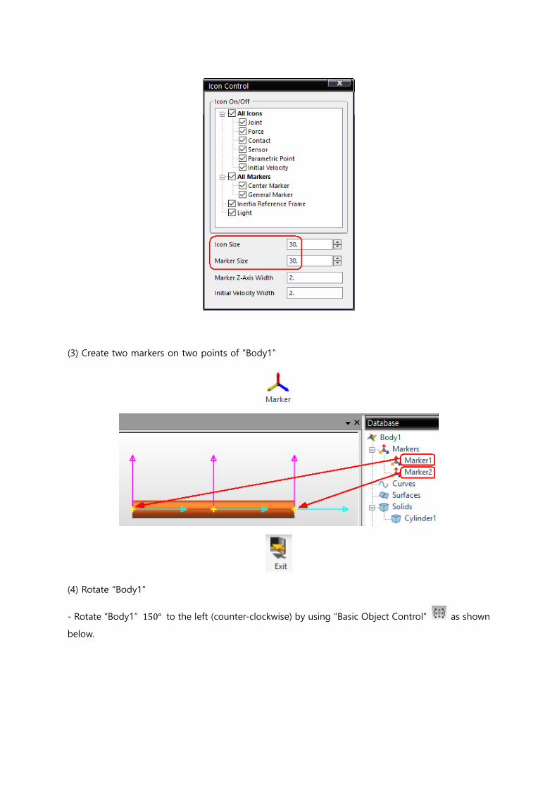
(3) Create two markers on two points of “Body1”
(4) Rotate “Body1”
- Rotate “Body1” 150° to the left (counter-clockwise) by using “Basic Object Control” as shown
below.
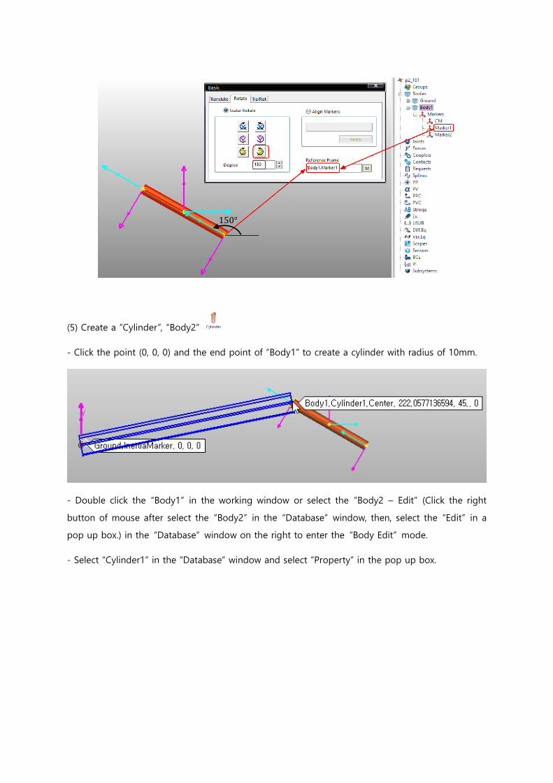
(5) Create a “Cylinder”, “Body2”
- Click the point (0, 0, 0) and the end point of “Body1” to create a cylinder with radius of 10mm.
- Double click the “Body1” in the working window or select the “Body2 – Edit” (Click the right
button of mouse after select the “Body2” in the “Database” window, then, select the “Edit” in a
pop up box.) in the “Database” window on the right to enter the “Body Edit” mode.
- Select “Cylinder1” in the “Database” window and select “Property” in the pop up box.
150°
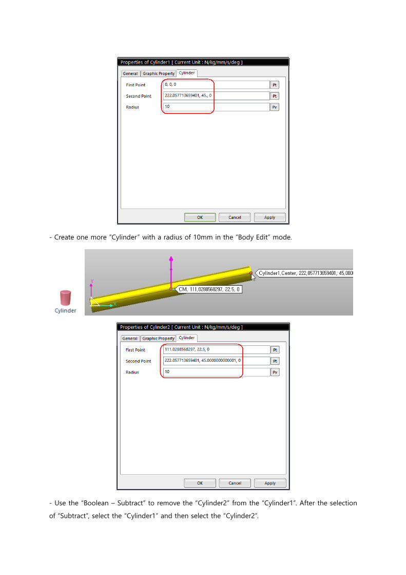
- Create one more “Cylinder” with a radius of 10mm in the “Body Edit” mode.
- Use the “Boolean – Subtract” to remove the “Cylinder2” from the “Cylinder1”. After the selection
of “Subtract”, select the “Cylinder1” and then select the “Cylinder2”.
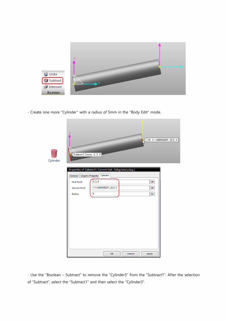
- Create one more “Cylinder” with a radius of 5mm in the “Body Edit” mode.
- Use the “Boolean – Subtract” to remove the “Cylinder3” from the “Subtract1”. After the selection
of “Subtract”, select the “Subtract1” and then select the “Cylinder3”.
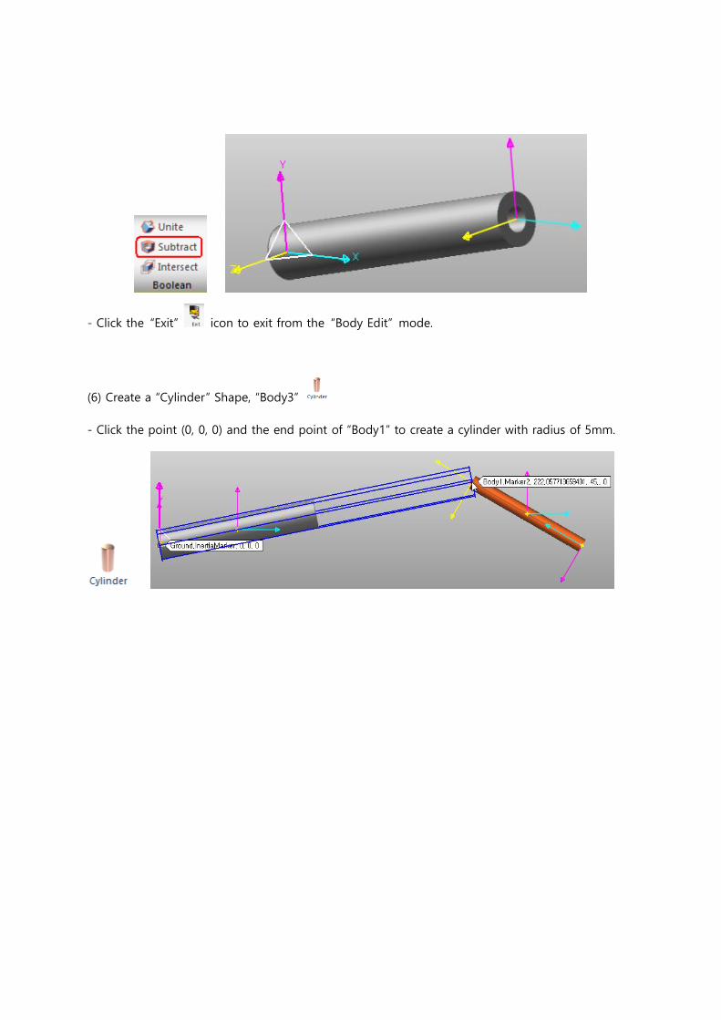
- Click the “Exit” icon to exit from the “Body Edit” mode.
(6) Create a “Cylinder” Shape, “Body3”
- Click the point (0, 0, 0) and the end point of “Body1” to create a cylinder with radius of 5mm.
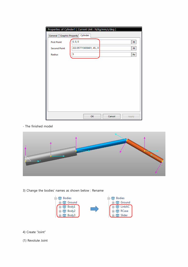
- The finished model
3) Change the bodies’ names as shown below : Rename
4) Create “Joint”
(1) Revolute Joint
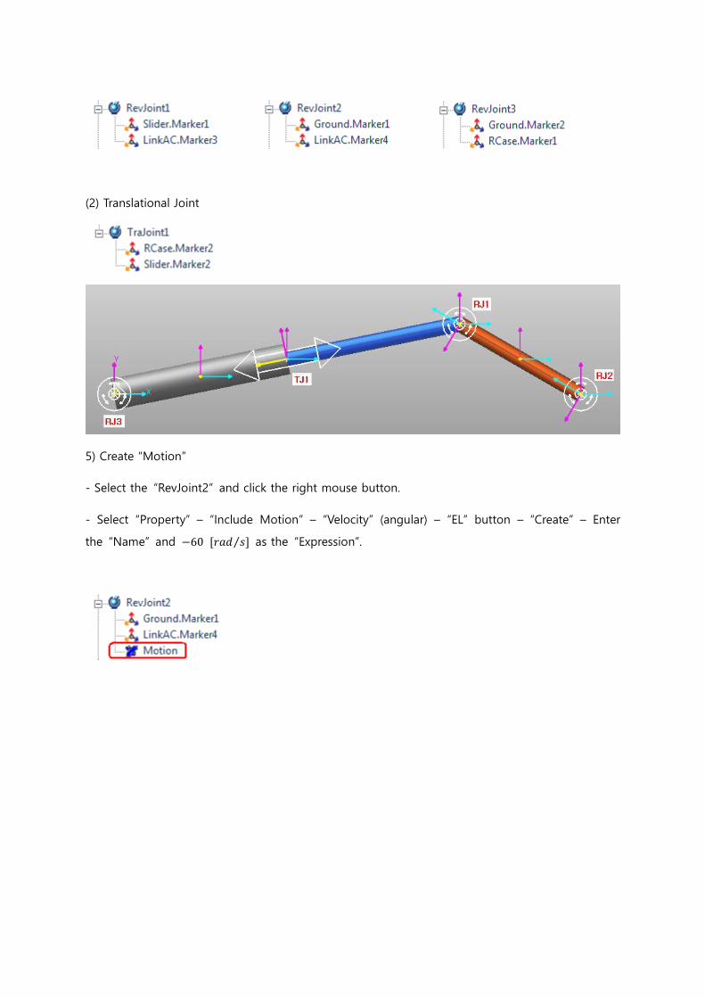
(2) Translational Joint
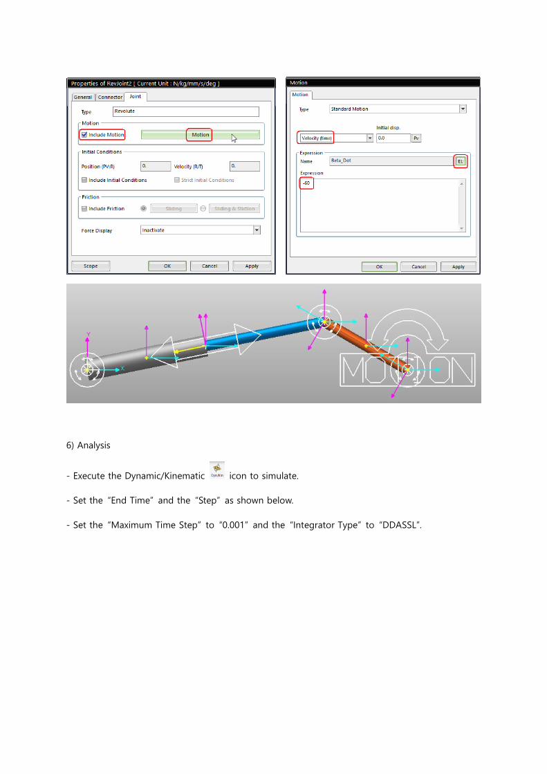
5) Create “Motion”
- Select the “RevJoint2” and click the right mouse button.
- Select “Property” – “Include Motion” – “Velocity” (angular) – “EL” button – “Create” – Enter
the “Name” and −60 [𝑟𝑎𝑑 𝑠⁄ ] as the “Expression”.
6) Analysis
- Execute the Dynamic/Kinematic icon to simulate.
- Set the “End Time” and the “Step” as shown below.
- Set the “Maximum Time Step” to “0.001” and the “Integrator Type” to “DDASSL”.
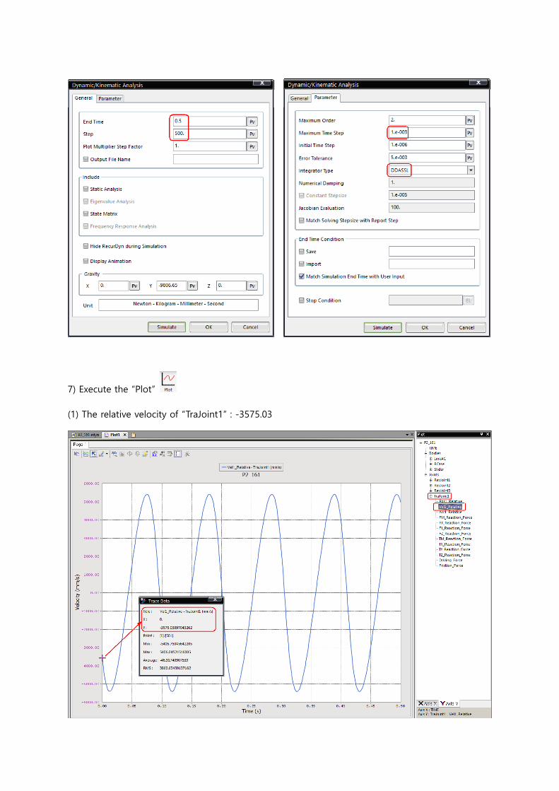
7) Execute the “Plot”
(1) The relative velocity of “TraJoint1” : -3575.03

(2) The relative acceleration of “TraJoint1” : -315118.34
(3) The angular velocity of “RCase” or the “Slider” : 17.86
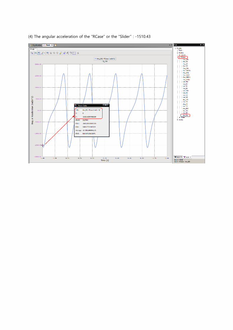
(4) The angular acceleration of the “RCase” or the “Slider” : -1510.43
3. Problems in Consideration
1) In this problem, the mass was not set. If the mass is smaller or larger than the original mass, how
do the results change?
2) If there is no difference, consider what the reason is.
3) An actuator should be installed in each revolute joint to induce a motion. The force that is needed
to induce a motion created by an actuator is the same as the reaction force of the joint. Calculate
the force (a reaction force) required to induce this motion. (Note: consider how the results change
with a different mass)
4) How many degrees of freedom are in this system? In other words, is this problem a “Dynamic”
problem or a “Kinematic” problem?