Embed Size (px)
Citation preview
Technical Data
Dynamix 1444 Series Monitoring System SpecificationsCatalog Numbers 1444-DYN04-01RA, 1444-TSCX02-02RB, 1444-RELX00-04RB, 1444-AOFX00-04RB, 1444-TB-A, 1444-TB-B
Summary of Changes
This publication contains new and updated information as indicated in the following table.
Additional Resources
These documents contain additional information concerning related products from Rockwell Automation.
You can view or download publications at http://www.rockwellautomation.com/global/literature-library/overview.page. To order paper copies of technical documentation, contact your local Allen-Bradley distributor or Rockwell Automation sales representative.
Topic Page
Hardware Specifications 6
Tachometer Signal Conditioner Expansion Module 1444-TSCX042-02RB 15
Fault Management 16
Relay Expansion Module 1444-RELX00-04RB 17
Resource Description
Industrial Automation Wiring and Grounding Guidelines, publication 1770-4.1 Provides general guidelines for installing a Rockwell Automation industrial system.
Product Certifications website, http://www.rockwellautomation.com/global/certification/overview.page Provides declarations of conformity, certificates, and other certification details.
Dynamix 1444 Series Monitoring System Specifications
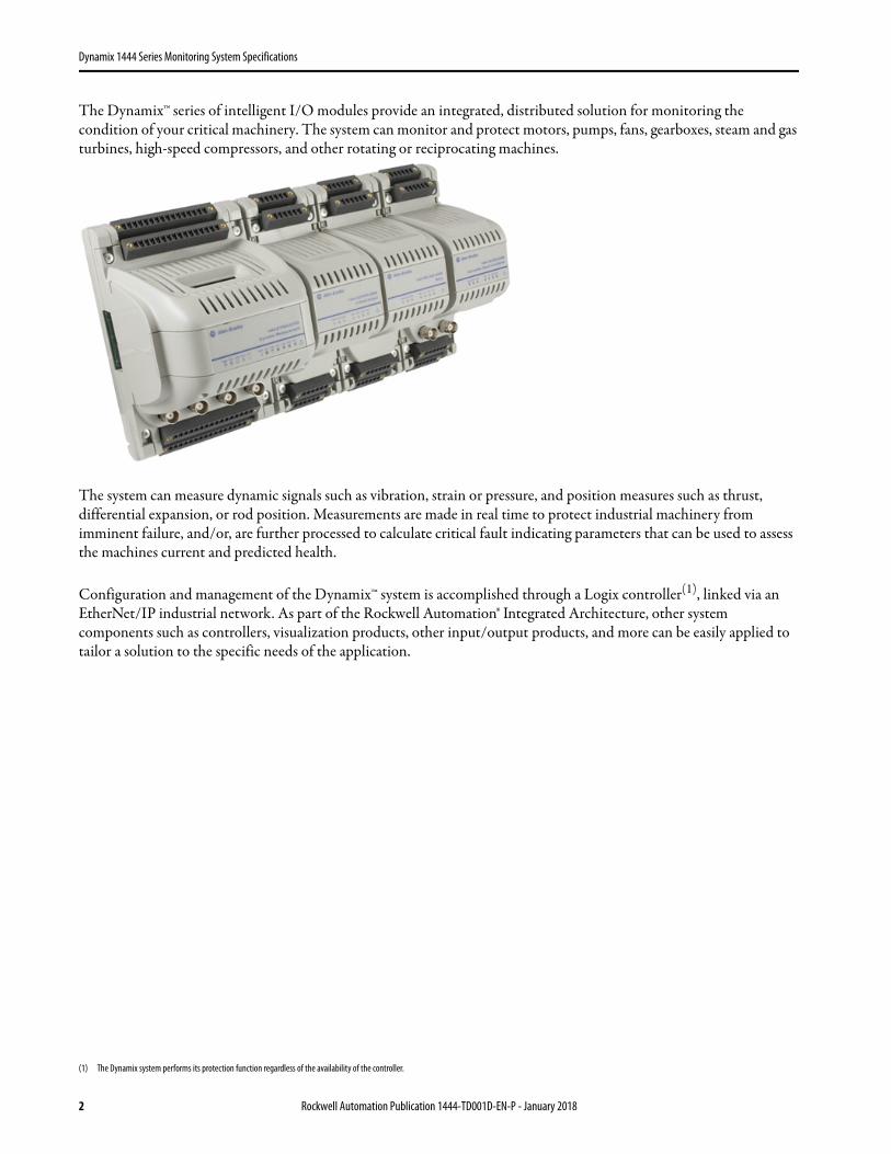
The Dynamix™ series of intelligent I/O modules provide an integrated, distributed solution for monitoring the condition of your critical machinery. The system can monitor and protect motors, pumps, fans, gearboxes, steam and gas turbines, high-speed compressors, and other rotating or reciprocating machines.
The system can measure dynamic signals such as vibration, strain or pressure, and position measures such as thrust, differential expansion, or rod position. Measurements are made in real time to protect industrial machinery from imminent failure, and/or, are further processed to calculate critical fault indicating parameters that can be used to assess the machines current and predicted health.
Configuration and management of the Dynamix™ system is accomplished through a Logix controller(1), linked via an EtherNet/IP industrial network. As part of the Rockwell Automation® Integrated Architecture, other system components such as controllers, visualization products, other input/output products, and more can be easily applied to tailor a solution to the specific needs of the application.
(1) The Dynamix system performs its protection function regardless of the availability of the controller.
2 Rockwell Automation Publication 1444-TD001D-EN-P - January 2018
Dynamix 1444 Series Monitoring System Specifications
The Dynamix series consists of just six core part numbers and various accessories for connectors and cables.
You can view or download publications at http://www.rockwellautomation.com/literature. To order paper copies of technical documentation, contact your local Allen-Bradley distributor or Rockwell Automation sales representative.
Dynamix 1444 Series Common
Dynamix 1444 series modules are designed to serve the condition monitoring requirements of rotating and reciprocating industrial machinery. The family includes the 1444-DYN04-01RA high performance, highly configurable main module. The 1444-TSCX02-02RB modules provide tachometer signal conditioning. The 1444-RELX00-04RB relays, 1444-AOFX00-04RB analog outputs, and 1444-TB-A/B terminal bases are also included in the family. The modules are applied in combinations as necessary to the application.
All 1444 series modules and terminal bases share the following common hardware specifications.
Table 1 - 1444 Series Catalog Numbers
Type Module Cat. No. Page
Measurement modules
Dynamic measurement module 1444-DYN04-01RA 5
Speed modules Tachometer signal conditioner expansion module 1444-TSCX02-02RB 15
Relay modules Relay expansion module 1444-RELX00-04RB 17
Analog output modules 4…20 mA expansion module 1444-AOFX00-04RB 18
Terminal bases
Dynamic measurement module terminal base 1444-TB-A 20
Expansion module terminal base 1444-TB-B 20
Table 2 - Removable Plug Connector Sets
Module Spring Connector Screw Connector Page
1444-DYN04-01RA 1444-DYN-RPC-SPR-01 1444-DYN-RPC-SCW-01 21
1444-TSCX02-02RB 1444-TSC-RPC-SPR-01 1444-TSC-RPC-SCW-01 21
1444-RELX00-04RB 1444-REL-RPC-SPR-01 1444-REL-RPC-SCW-01 21
1444-AOFX00-04RB 1444-AOF-RPC-SPR-01 1444-AOF-RPC-SCW-01 21
Terminal Base
1444-TB-A 1444-TBA-RPC-SPR-01 1444-TBA-RPC-SCW-01 21
1444-TB-B 1444-TBB-RPC-SPR-01 1444-TBB-RPC-SCW-01 21
Table 3 - 1444 Series Interconnect Cable Accessories
Cat. No. Description Page
1444-LBIC-04 Local bus interconnect cable (qty 4) 22
1444-LBXC-0M3-01 Local bus extender cable (0.3 m) 22
1444-LBXC-1M0-01 Local bus extender cable (1.0 m) 22
Table 4 - 1444 Series Common Hardware Specifications
Attribute1444-DYN04-01RA, 1444-TSCX02-02RB, 1444-RELX00-04RB, 1444-AOFX00-04RB, 1444-TB-A/B
Technical Specifications
Enclosure type rating None (open-style)
North American temp code T4
IEC temp code T4
Power
Voltage
North American:18...32V, max 8 A,Limited Voltage Source
ATEX/IECEx:18...32V, max 8 ASELV/PELV Source
Conformal Coating
All printed circuit boards are conformal coated in accordance with IPC-A-610C and in compliance with:
• IPC-CC-830 B• UL508
Environmental Specifications
Temperature, operatingIEC 60068-2-1 (Test Ad, Operating Cold), IEC 60068-2-2 (Test Bd, Operating Dry Heat), IEC 60068-2-14 (Test Nb, Operating Thermal Shock):
-25…70 °C (-13…158 °F)
Temperature, surrounding air, max 70 °C (158 °F)
Temperature, nonoperatingIEC 60068-2-1 (Test Ab, Unpackaged nonoperating Cold),IEC 60068-2-2 (Test Bb, Unpackaged nonoperating Dry Heat),IEC 60068-2-14 (Test N/A, Unpackaged nonoperating Thermal Shock):
-40…85 °C (-40…185 °F)
Relative humidityIEC 60068-2-30 (Test dB, Unpackaged Damp Heat):
5…95% noncondensing
VibrationPer IEC 600068-2-6 (Test Fc, Operating): 2 g @ 10…500 Hz
Rockwell Automation Publication 1444-TD001D-EN-P - January 2018 3
Dynamix 1444 Series Monitoring System Specifications
API-670 Compliance
The 1444 series is designed in accordance with the relevant sections of the 5th Edition of the American Petroleum Institutes (API) standard 670,(1) ‘Machinery Protection Systems’.
Local Bus
The 1444 series family includes a power and communication bus that, similarly to the backplane of a rack-based system, connects a series of modules.(2) The local bus is implemented by using simple ribbon connectors that typically span adjacent modules.(3)
Insert and Remove Under Power
All 1444 series modules can be removed and replaced while power is applied to its terminal base(4)(5).
Shock, operatingIEC 60068-2-27 (Test Ea, Unpackaged Shock):
15 g
Shock, nonoperatingIEC 60068-2-27 (Test Ea, Unpackaged Shock):
30 g
Emissions IEC 61000-6-4
ESD immunityIEC 61000-4-2:
6 kV contact discharges8 kV air discharges
Radiated RF immunityIEC 61000-4-3:
10V/m with 1 kHz sine-wave 80% AM from 80…2000 MHz10V/m with 200 Hz 50% Pulse 100% AM at 900 MHz1V/m with 1 kHz sine-wave 80% AM from 2000…2700 MHz
Conducted RF immunityIEC 61000-4-6:
10V rms with 1 kHz sine-wave 80% AM from 150 kHz…80 MHz
Certifications(1)
c-UL-us
UL Listed Industrial Control Equipment, which is certified for US and Canada. See UL File E65584.UL Listed for Class I, Division 2 Group A,B,C,D Hazardous Locations, which are certified for U.S. and Canada. See UL File E194810.
CE
European Union 2004/108/EC EMC Directive, compliant with:• EN 61326-1; Meas./Control/Lab, Industrial
Requirements• EN 61000-6-2; Industrial Immunity• EN 61000-6-4; Industrial Emissions• EN 61131-2; Programmable Controllers (Clause
8, Zone A & B)European Union 2006/95/EC LVD, compliant with:(2)
EN 61131-2; Programmable Controllers (Clause 11)
RCM EN 61000-6-4; Industrial Emissions
Ex
European Union 94/9/EC ATEX Directive, compliant with:• EN 60079-15; Potentially Explosive
Atmospheres, Protection “n”• EN 60079-0; General Requirements• II 3 G Ex N/A IIC T4 Gc• II 3 G Ex N/A nC IIC T4 Gc (only 1444-DYN04-
01RA and 1444-RELX00-04RB)• DEMKO14ATEX1365X
IECEx
IECEx System, compliant with:• IEC 60079-15; Potentially Explosive
Atmospheres, Protection “n”• IEC 60079-0; General Requirements• II 3 G Ex N/A IIC T4 Gc• II 3 G Ex N/A nC IIC T4 Gc (only 1444-DYN04-
01RA and 1444-RELX00-04RB)• IECEx UL 14.0082X
KCKorean Registration of Broadcasting and Communications Equipment, compliant with:Article 58-2 of Radio Waves Act, Clause 3
(1) When product or packaging is marked see the Product Certification link at http://www.rockwellautomation.com/ for Declarations of Conformity.
(2) Applies to only 1444-DYN04-01RA and 1444-RELX00-04RB modules.
Table 4 - 1444 Series Common Hardware Specifications (continued)
Attribute1444-DYN04-01RA, 1444-TSCX02-02RB, 1444-RELX00-04RB, 1444-AOFX00-04RB, 1444-TB-A/B
(1) Whether a system is compliant is dependent on the components that are provided, the various optional elements of the standard that you require, and the configuration of the installed system.
(2) Any main module must be installed to the left of any expansion modules that it manages.(3) A short ribbon cable, suitable for connecting adjacent modules, is included with each terminal base. See
the Accessories, section of this publication for a description of available extended length cables.
Table 5 - Local Bus Function
Attribute Description
Power
Passes power from each main module (1444-DYN04-01RA) to its expansion modules
Power is not passed between main modules
When redundant power supplies are connected to a main module, only the voted power source is distributed to its expansion modules.
TTL signals
Dual independent TTL signals, with tachometer sensor status, are passed on the Local Bus
There can be only one tachometer expansion module on a local bus
The TTL signal can serve up to six main modules
CommunicationA digital network that is used between a main module and its expansion modules is implemented on the local bus
Communication does not link main modules
WARNING:
• If you insert or remove the module while backplane power is on, an electric arc can occur. This arc could cause an explosion in hazardous location installations. Be sure that power is removed or the area is nonhazardous before proceeding.
• If you connect or disconnect wiring while the field-side power is on, an electric arc can occur. This arc could cause an explosion in hazardous location installations. Be sure that power is removed or the area is nonhazardous before proceeding.
(4) If a removed module includes an energized relay, the relay goes to its de-energized state.(5) If Ethernet is daisy chained, one module to the next, and DLR is not used, removal of a main module causes
the loss of Ethernet communication to all ‘downstream’ main modules.
4 Rockwell Automation Publication 1444-TD001D-EN-P - January 2018
Dynamix 1444 Series Monitoring System Specifications
Mounting and Connections
DIN Rail
Terminal bases require DIN mounting by using 35 x 7.5 mm rail.
1444 series modules do not connect ground to the DIN rail, therefore coated DIN rail is acceptable.
Wiring Connectors
Field wiring landed to 1444 series modules and terminal bases are via 45°, front access, removable plug connectors with screw, and spring-cage connectors available(1).
Each connector is keyed such that it can be inserted into the location on the module or terminal base that it serves. Connectors are secured in place by quarter-turn screws.
Controller Independence
While the 1444 series is dependent on a Logix controller for its initial configuration, it is not dependent on the controller to perform its protection function. If communication with the controller is lost, the system continues to perform measurements, evaluate alarm conditions and, if necessary, actuate its relays. It also remains available to serve data to other hosts(2) that can remain accessible.
Nonvolatile Memory
After its initial configuration, a 1444 series Main Module maintains its configuration in nonvolatile memory. After any subsequent power cycle, the module loads its configuration from the nonvolatile memory and resumes its normal function. This process makes sure that even if the controller is not accessible after powerup that the monitor performs its function.
Dynamic Measurement Module 1444-DYN04-01RA
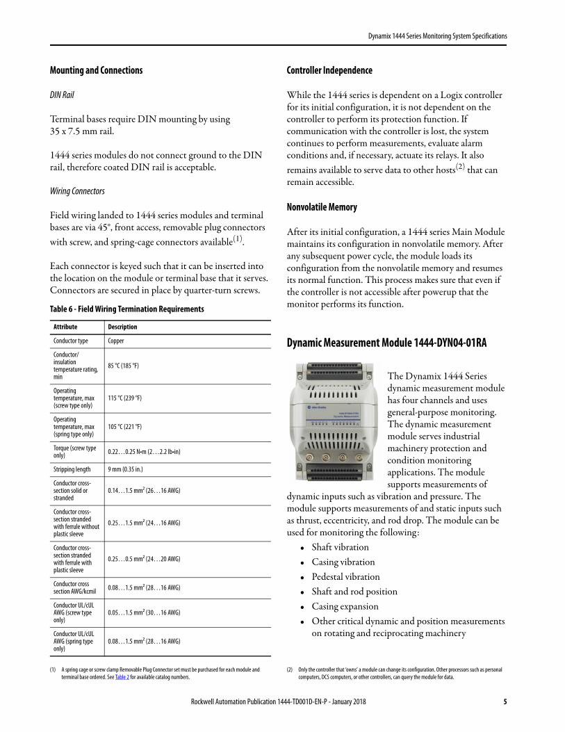
The Dynamix 1444 Series dynamic measurement module has four channels and uses general-purpose monitoring. The dynamic measurement module serves industrial machinery protection and condition monitoring applications. The module supports measurements of
dynamic inputs such as vibration and pressure. The module supports measurements of and static inputs such as thrust, eccentricity, and rod drop. The module can be used for monitoring the following:
• Shaft vibration• Casing vibration• Pedestal vibration• Shaft and rod position• Casing expansion• Other critical dynamic and position measurements
on rotating and reciprocating machinery
(1) A spring cage or screw clamp Removable Plug Connector set must be purchased for each module and terminal base ordered. See Table 2 for available catalog numbers.
Table 6 - Field Wiring Termination Requirements
Attribute Description
Conductor type Copper
Conductor/insulation temperature rating, min
85 °C (185 °F)
Operating temperature, max (screw type only)
115 °C (239 °F)
Operating temperature, max (spring type only)
105 °C (221 °F)
Torque (screw type only) 0.22…0.25 N•m (2…2.2 lb•in)
Stripping length 9 mm (0.35 in.)
Conductor cross-section solid or stranded
0.14…1.5 mm2 (26…16 AWG)
Conductor cross-section stranded with ferrule without plastic sleeve
0.25…1.5 mm2 (24…16 AWG)
Conductor cross-section stranded with ferrule with plastic sleeve
0.25…0.5 mm2 (24…20 AWG)
Conductor cross section AWG/kcmil 0.08…1.5 mm2 (28…16 AWG)
Conductor UL/cUL AWG (screw type only)
0.05…1.5 mm2 (30…16 AWG)
Conductor UL/cUL AWG (spring type only)
0.08…1.5 mm2 (28…16 AWG)
(2) Only the controller that ‘owns’ a module can change its configuration. Other processors such as personal computers, DCS computers, or other controllers, can query the module for data.
Rockwell Automation Publication 1444-TD001D-EN-P - January 2018 5
Dynamix 1444 Series Monitoring System Specifications
To achieve this degree of adaptability, the module couples an extraordinarily flexible firmware and a powerful multi-processor hardware platform.
The 1444-DYN04-01RA module is designed specifically for integration with Allen-Bradley® (Logix5000™) controllers that are connected across an industrial Ethernet network. This design makes the 1444 series unequaled in its ability to serve as a synergetic member of larger total facility control and information management systems.
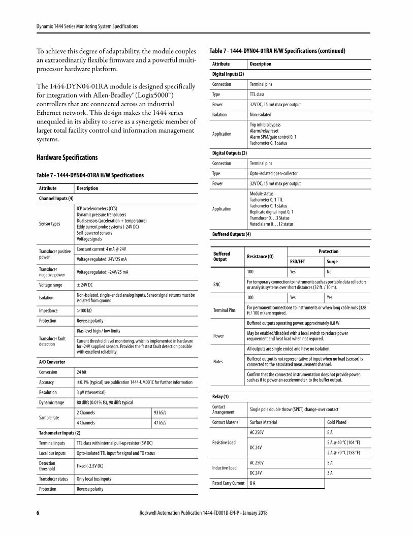
Hardware Specifications
Table 7 - 1444-DYN04-01RA H/W Specifications
Attribute Description
Channel Inputs (4)
Sensor types
ICP accelerometers (CCS)Dynamic pressure transducersDual sensors (acceleration + temperature)Eddy current probe systems (-24V DC)Self-powered sensorsVoltage signals
Transducer positive power
Constant current: 4 mA @ 24V
Voltage regulated: 24V/25 mA
Transducer negative power Voltage regulated: -24V/25 mA
Voltage range ± 24V DC
Isolation Non-isolated, single-ended analog inputs. Sensor signal returns must be isolated from ground
Impedance >100 kΩ
Protection Reverse polarity
Transducer fault detection
Bias level high / low limits
Current threshold level monitoring, which is implemented in hardware for -24V supplied sensors. Provides the fastest fault detection possible with excellent reliability.
A/D Converter
Conversion 24 bit
Accuracy ±0.1% (typical) see publication 1444-UM001C for further information
Resolution 3 μV (theoretical)
Dynamic range 80 dBfs (0.01% fs), 90 dBfs typical
Sample rate2 Channels 93 kS/s
4 Channels 47 kS/s
Tachometer Inputs (2)
Terminal inputs TTL class with internal pull-up resistor (5V DC)
Local bus inputs Opto-isolated TTL input for signal and TX status
Detection threshold Fixed (-2.5V DC)
Transducer status Only local bus inputs
Protection Reverse polarity
Digital Inputs (2)
Connection Terminal pins
Type TTL class
Power 32V DC, 15 mA max per output
Isolation Non-isolated
Application
Trip inhibit/bypassAlarm/relay resetAlarm SPM/gate control 0, 1Tachometer 0, 1 status
Digital Outputs (2)
Connection Terminal pins
Type Opto-isolated open-collector
Power 32V DC, 15 mA max per output
Application
Module statusTachometer 0, 1 TTLTachometer 0, 1 statusReplicate digital input 0, 1Transducer 0…3 StatusVoted alarm 0…12 status
Buffered Outputs (4)
Relay (1)
Contact Arrangement Single pole double throw (SPDT) change-over contact
Contact Material Surface Material Gold Plated
Resistive Load
AC 250V 8 A
DC 24V5 A @ 40 °C (104 °F)
2 A @ 70 °C (158 °F)
Inductive LoadAC 250V 5 A
DC 24V 3 A
Rated Carry Current 8 A
Table 7 - 1444-DYN04-01RA H/W Specifications (continued)
Attribute Description
Buffered Output Resistance (Ω)
Protection
ESD/EFT Surge
100 Yes No
BNC For temporary connection to instruments such as portable data collectors or analysis systems over short distances (32 ft. / 10 m).
100 Yes Yes
Terminal Pins For permanent connections to instruments or when long cable runs (328 ft / 100 m) are required.
Buffered outputs operating power: approximately 0.8 W
Power May be enabled/disabled with a local switch to reduce power requirement and heat load when not required.
All outputs are single ended and have no isolation.
Notes Buffered output is not representative of input when no load (sensor) is connected to the associated measurement channel.
Confirm that the connected instrumentation does not provide power, such as if to power an accelerometer, to the buffer output.
6 Rockwell Automation Publication 1444-TD001D-EN-P - January 2018
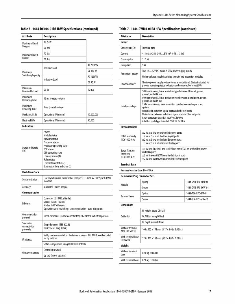
Dynamix 1444 Series Monitoring System Specifications
Maximum Rated Voltage
AC 250V
DC 24V
Maximum Rated Current
AC 8 A
DC 5 A
Maximum Switching Capacity
Resistive LoadAC 2000VA
DC 150 W
Inductive LoadAC 1250VA
DC 90 W
Minimum Permissible Load DC 5V 10 mA
Maximum Operating Time 15 ms @ rated voltage
Maximum Releasing Time 5 ms @ rated voltage
Mechanical Life Operations (Minimum) 10,000,000
Electrical Life Operations (Minimum) 50,000
Indicators
Status indicators (16)
PowerModule statusNetwork statusProcessor statusProcessor operating stateDSP statusDSP operating stateChannel status (4)Relay statusEthernet link status (2)Ethernet activity indicator (2)
Real-Time Clock
Synchronization Clock synchronized to controller time per IEEE-1588 V2 / CIP Sync (ODVA) standard
Accuracy Max drift: 100 ms per year
Communication
Ethernet
Connector (2): RJ45, shieldedSpeed: 10 MB/100 MBModes: half/full duplexOperation: auto-switching - auto negotiation - auto mitigation
Communication protocol ODVA-compliant (conformance tested) EtherNet/IP industrial protocol
Supported connectivity protocols
Single Ethernet (IEEE 802.3)Device Level Ring (ODVA)
IP addressSet by hardware switch on the terminal base as 192.168.0.xxx (last octet set by switch)
Set in configuration using DHCP/BOOTP tools
Concurrent accessController (owner)
Up to 3 (more) sessions
Table 7 - 1444-DYN04-01RA H/W Specifications (continued)
Attribute Description
Power
Connections (2) Terminal pins
Current 411 mA @ 24V (546…319 mA @ 18…32V)
Consumption 11.5 W
Dissipation 9 W
Redundant powerTwo 18…32V DC, max 8 A SELV power supply inputs
Higher voltage supply is applied to main and expansion modules
PowerMonitor™ The two power supply voltage levels are monitored. Status indicated via process operating status indicators and on controller input (I/O).
Isolation voltage
50V (continuous), basic insulation type between Ethernet, power, ground, and AUX bus50V (continuous), basic insulation type between signal ports, power, ground, and AUX bus250V (continuous), basic insulation type between relay ports and systemNo isolation between signal ports and Ethernet portsNo isolation between individual signal ports or Ethernet portsRelay ports type tested at 1500V AC for 60 sAll other ports type tested at 707V DC for 60 s
Environmental
EFT/B ImmunityIEC 61000-4-4:
±2 kV at 5 kHz on unshielded power ports±2 kV at 5 kHz on shielded signal ports±2 kV at 5 kHz on shielded Ethernet ports±3 kV at 5 kHz on unshielded relay ports
Surge Transient ImmunityIEC 61000-4-5:
±1 kV line-line(DM) and ±2 kV line-earth(CM) on unshielded power and relay ports±2 kV line-earth(CM) on shielded signal ports±2 kV line-earth(CM) on shielded Ethernet ports
Terminal Base
Requires terminal base 1444-TB-A
Removable Plug Connector Sets
ModuleSpring 1444-DYN-RPC-SPR-01
Screw 1444-DYN-RPC-SCW-01
Terminal baseSpring 1444-TBA-RPC-SPR-01
Screw 1444-TBA-RPC-SCW-01
Dimensions
Definition
H: Height above DIN rail
W: Width along DIN rail
D: Depth across DIN rail
Without terminal base (H x W x D) 106 x 102 x 154 mm (4.17 x 4.02 x 6.06 in.)
With terminal base (H x W x D) 125 x 102 x 158 mm (4.92 x 4.02 x 6.22 in.)
Weight
Without terminal base 0.40 kg (0.88 lb)
With terminal base 0.58 kg (1.28 lb)
Table 7 - 1444-DYN04-01RA H/W Specifications (continued)
Attribute Description
Rockwell Automation Publication 1444-TD001D-EN-P - January 2018 7
Dynamix 1444 Series Monitoring System Specifications
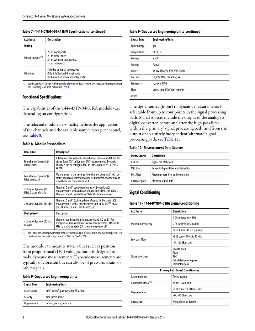
Functional Specifications
The capabilities of the 1444-DYN04-01RA module vary depending on configuration.
The selected module personality defines the application of the channels and the available sample rates per channel, see Table 8.
The module can measure static values such as position from proportional (DC) voltages, but it is designed to make dynamic measurements. Dynamic measurements are typically of vibration but can also be of pressure, strain, or other signals.
The signal source (input) to dynamic measurements is selectable from up to four points in the signal processing path. Signal sources include the output of the analog to digital converter, before and after the high pass filter within the ‘primary’ signal processing path, and from the output of an entirely independent ‘alternate’ signal processing path, see Table 11.
Signal Conditioning
Wiring
Wiring category(1)
2 - on signal ports2 - on power ports2 - on communications ports1 - on relay ports
Wire typeShielded on signal connectionsOnly Shielded on Ethernet portsUnshielded on power and relay ports
(1) Use this Conductor Category information for planning conductor routing. See Industrial Automation Wiring and Grounding Guidelines, publication 1770-4.1.
Table 8 - Module Personalities
Real-Time Description
Four channel dynamic (4 kHz) or static
All channels are available. Each channel pair can be defined for either Static (DC) or Dynamic (AC) measurements. Dynamic channels can be configured for an FMAX up to 4578 Hz (274.7 kCPM).
Four channel dynamic (4 kHz), dual path
Measurement is the same as “four channel dynamic (4 kHz) or static”. Inputs are internally connected between channels 0 and 2 and between channels 1 and 3.
2 channel dynamic (20 kHz), 2 channel static
Channels 0 and 1 can be configured for Dynamic (AC) measurements with an FMAX of up to 20.6 kHz (1236 kCPM). Channels 2 and 3 available for Static (DC) measurements.
2 channel dynamic (40 kHz)Channels 0 and 1 (pair) can be configured for Dynamic (AC) measurements with a measurement span of 40 kHz(1), or as gSE. Channels 2 and 3 are disabled (off).
(1) The 40 kHz personality provides high frequency overall and gSE measurements. The maximum possible FFT FMAX available from a 40 kHz personality is 2747 Hz (164.8 kCPM).
Multiplexed Description
4 channel dynamic (40 kHz) or static
Channels can be configured in pairs (0 and 1, 2 and 3) for Dynamic (AC) measurements with a measurement FMAX of 40 kHz(1), as gSE, as Static (DC) measurements, or off.
Table 9 - Supported Engineering Units
Signal Type Engineering Units
Acceleration m/s2, inch/s2, g, mm/s2, mg, RPM/min
Velocity m/s, inch/s, mm/s
Displacement m, mm, micron, inch, mil
Table 7 - 1444-DYN04-01RA H/W Specifications (continued)
Attribute Description
Spike energy gSE
Temperature °K, °C, °F
Voltage V, mV
Current A, mA
Power W, kW, MW, VA, kVA, VAR, kVAR,
Pressure Pa, kPa, MPa, bar, mbar, psi
Frequency Hz, cpm, RPM
Flow l/min, cgm, US g/min, m3/min
Other EU
Table 10 - Measurement Data Sources
Meas. Source Description
ADC out Signal out of the ADC
Mid filter Before high pass filter and integration
Post filter After high pass filter and integration
Alternate path Alternate signal path
Table 11 - 1444-DYN04-01RA Signal Conditioning
Attribute Description
Maximum frequency
4 Ch. protection: 4 kHz
2 Ch. protection: 20.6 kHz
Surveillance: 40 kHz (OA only)
Low pass filter-3 dB corner 10 Hz to 40 kHz
-24, -60 dB/octave
Signal detection
Peak to peakPeakRMSCalculated peak to peakCalculated peak
Primary Path Signal Conditioning
Sampling mode Asynchronous
Bandwidth FMAX (1) 35 Hz…20.6 kHz
High pass filter-3 dB corner: 0.1 Hz to 1 kHz
-24, -60 dB/octave
Integration None, single or double
Table 9 - Supported Engineering Units (continued)
Signal Type Engineering Units
8 Rockwell Automation Publication 1444-TD001D-EN-P - January 2018
Dynamix 1444 Series Monitoring System Specifications
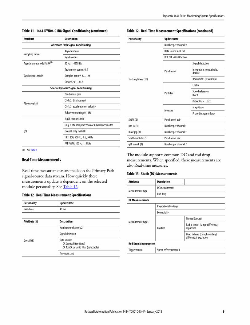
Real-Time Measurements
Real-time measurements are made on the Primary Path signal-source data stream. How quickly these measurements update is dependent on the selected module personality. See Table 12.
The module supports common DC and rod drop measurements. When specified, these measurements are also Real-time measures.
Alternate Path Signal Conditioning
Sampling modeAsynchronous
Synchronous
Asynchronous mode FMAX(1) 30 Hz…4578 Hz
Synchronous mode
Tachometer source: 0, 1
Samples per rev: 8…128
Orders: 2.0…31.3
Special Dynamic Signal Conditioning
Absolute shaft
Per channel pair
Ch-0/2: displacement
Ch-1/3: acceleration or velocity
Relative mounting: 0°, 180°
gSE
2 gSE channels max
Only 2-channel protection or surveillance modes
Overall, only TWF/FFT
HPF: 200, 500 Hz, 1, 2, 5 kHz
FFT FMAX: 100 Hz…5 kHz
(1) See Table 7
Table 12 - Real-Time Measurement Specifications
Personality Update Rate
Real-time 40 ms
Attribute (#) Description
Overall (8)
Number per channel: 2
Signal detection
Data source: OA 0: post filter (fixed)OA 1: ADC out/mid filter (selectable)
Time constant
Table 11 - 1444-DYN04-01RA Signal Conditioning (continued)
Attribute Description
Tracking filters (16)
Number per channel: 4
Data source: ADC out
Roll Off: -48 dB/octave
Per channel
Signal detection
Integration: none, single, double
Revolutions (resolution)
Per filter
Enable
Speed reference:0 or 1
Order: 0.25…32x
MeasureMagnitude
Phase (integer orders)
SMAX (2) Per channel pair
Not 1x (4) Number per channel: 1
Bias/gap (4) Number per channel: 1
Shaft absolute (2) Per channel pair
gSE overall (2) Number per channel: 1
Table 13 - Static (DC) Measurements
Attribute Description
Measurement typeDC measurement
Rod drop
DC Measurements
Measurement types
Proportional voltage
Eccentricity
Position
Normal (thrust)
Radial cancel (ramp) differential expansion
Head to head (complimentary) differential expansion
Rod Drop Measurement
Trigger source Speed reference: 0 or 1
Table 12 - Real-Time Measurement Specifications (continued)
Personality Update Rate
Rockwell Automation Publication 1444-TD001D-EN-P - January 2018 9
Dynamix 1444 Series Monitoring System Specifications
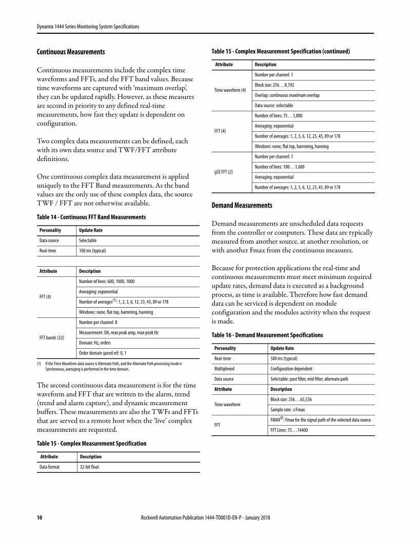
Continuous Measurements
Continuous measurements include the complex time waveforms and FFTs, and the FFT band values. Because time waveforms are captured with ‘maximum overlap’, they can be updated rapidly. However, as these measures are second in priority to any defined real-time measurements, how fast they update is dependent on configuration.
Two complex data measurements can be defined, each with its own data source and TWF/FFT attribute definitions.
One continuous complex data measurement is applied uniquely to the FFT Band measurements. As the band values are the only use of these complex data, the source TWF / FFT are not otherwise available.
The second continuous data measurement is for the time waveform and FFT that are written to the alarm, trend (trend and alarm capture), and dynamic measurement buffers. These measurements are also the TWFs and FFTs that are served to a remote host when the ‘live’ complex measurements are requested.
Demand Measurements
Demand measurements are unscheduled data requests from the controller or computers. These data are typically measured from another source, at another resolution, or with another Fmax from the continuous measures.
Because for protection applications the real-time and continuous measurements must meet minimum required update rates, demand data is executed as a background process, as time is available. Therefore how fast demand data can be serviced is dependent on module configuration and the modules activity when the request is made.
Table 14 - Continuous FFT Band Measurements
Personality Update Rate
Data source Selectable
Real-time 100 ms (typical)
Attribute Description
FFT (4)
Number of lines: 600, 1000, 1800
Averaging: exponential
Number of averages(1): 1, 2, 3, 6, 12, 23, 45, 89 or 178
(1) If the Time Waveform data source is Alternate Path, and the Alternate Path processing mode is Synchronous, averaging is performed in the time domain.
Windows: none, flat top, hamming, hanning
FFT bands (32)
Number per channel: 8
Measurement: OA, max peak amp, max peak Hz
Domain: Hz, orders
Order domain speed ref: 0, 1
Table 15 - Complex Measurement Specification
Attribute Description
Data format 32-bit float
Time waveform (4)
Number per channel: 1
Block size: 256…8,192
Overlap: continuous maximum overlap
Data source: selectable
FFT (4)
Number of lines: 75…1,800
Averaging: exponential
Number of averages: 1, 2, 3, 6, 12, 23, 45, 89 or 178
Windows: none, flat top, hamming, hanning
gSE FFT (2)
Number per channel: 1
Number of lines: 100…1,600
Averaging: exponential
Number of averages: 1, 2, 3, 6, 12, 23, 45, 89 or 178
Table 16 - Demand Measurement Specifications
Personality Update Rate
Real-time 500 ms (typical)
Multiplexed Configuration dependent
Data source Selectable: post filter, mid filter, alternate path
Attribute Description
Time waveformBlock size: 256…65,536
Sample rate: ≤Fmax
FFTFMAXSP: Fmax for the signal path of the selected data source
FFT Lines: 75…14400
Table 15 - Complex Measurement Specification (continued)
Attribute Description
10 Rockwell Automation Publication 1444-TD001D-EN-P - January 2018
Dynamix 1444 Series Monitoring System Specifications
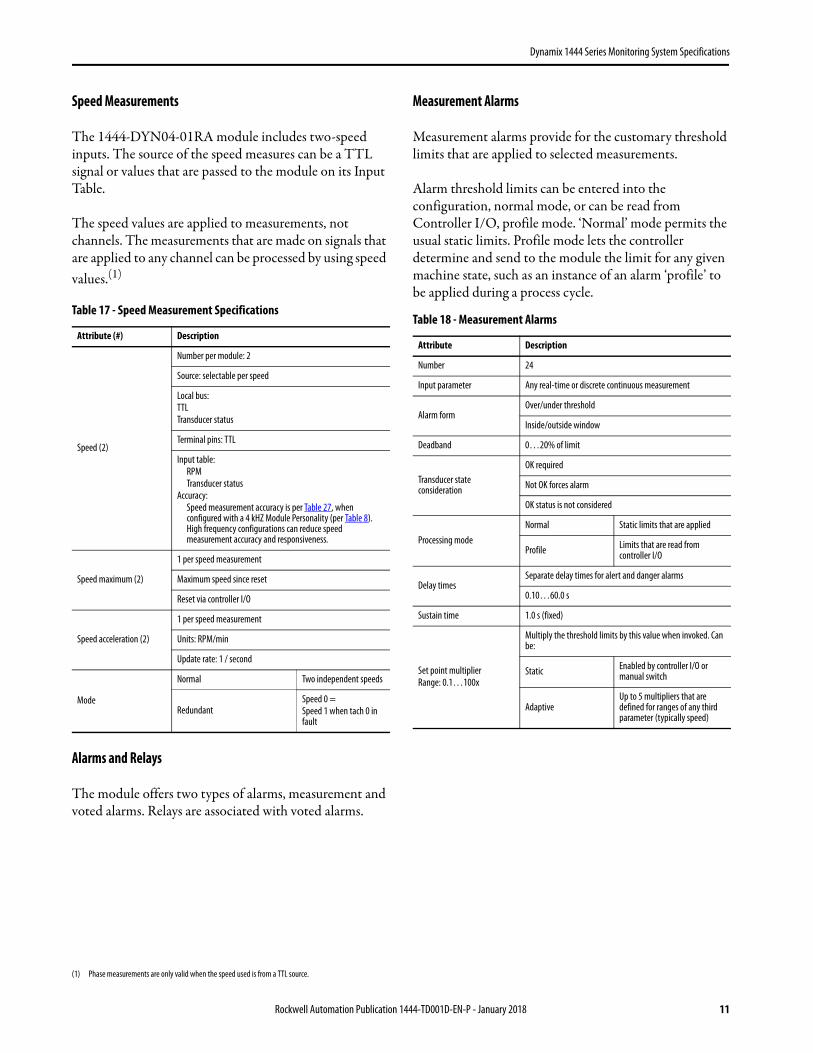
Speed Measurements
The 1444-DYN04-01RA module includes two-speed inputs. The source of the speed measures can be a TTL signal or values that are passed to the module on its Input Table.
The speed values are applied to measurements, not channels. The measurements that are made on signals that are applied to any channel can be processed by using speed values.(1)
Alarms and Relays
The module offers two types of alarms, measurement and voted alarms. Relays are associated with voted alarms.
Measurement Alarms
Measurement alarms provide for the customary threshold limits that are applied to selected measurements.
Alarm threshold limits can be entered into the configuration, normal mode, or can be read from Controller I/O, profile mode. ‘Normal’ mode permits the usual static limits. Profile mode lets the controller determine and send to the module the limit for any given machine state, such as an instance of an alarm ‘profile’ to be applied during a process cycle.
(1) Phase measurements are only valid when the speed used is from a TTL source.
Table 17 - Speed Measurement Specifications
Attribute (#) Description
Speed (2)
Number per module: 2
Source: selectable per speed
Local bus:TTLTransducer status
Terminal pins: TTL
Input table:RPMTransducer status
Accuracy:Speed measurement accuracy is per Table 27, when configured with a 4 kHZ Module Personality (per Table 8). High frequency configurations can reduce speed measurement accuracy and responsiveness.
Speed maximum (2)
1 per speed measurement
Maximum speed since reset
Reset via controller I/O
Speed acceleration (2)
1 per speed measurement
Units: RPM/min
Update rate: 1 / second
Mode
Normal Two independent speeds
RedundantSpeed 0 = Speed 1 when tach 0 in fault
Table 18 - Measurement Alarms
Attribute Description
Number 24
Input parameter Any real-time or discrete continuous measurement
Alarm formOver/under threshold
Inside/outside window
Deadband 0…20% of limit
Transducer state consideration
OK required
Not OK forces alarm
OK status is not considered
Processing modeNormal Static limits that are applied
Profile Limits that are read from controller I/O
Delay timesSeparate delay times for alert and danger alarms
0.10…60.0 s
Sustain time 1.0 s (fixed)
Set point multiplierRange: 0.1…100x
Multiply the threshold limits by this value when invoked. Can be:
Static Enabled by controller I/O or manual switch
AdaptiveUp to 5 multipliers that are defined for ranges of any third parameter (typically speed)
Rockwell Automation Publication 1444-TD001D-EN-P - January 2018 11
Dynamix 1444 Series Monitoring System Specifications
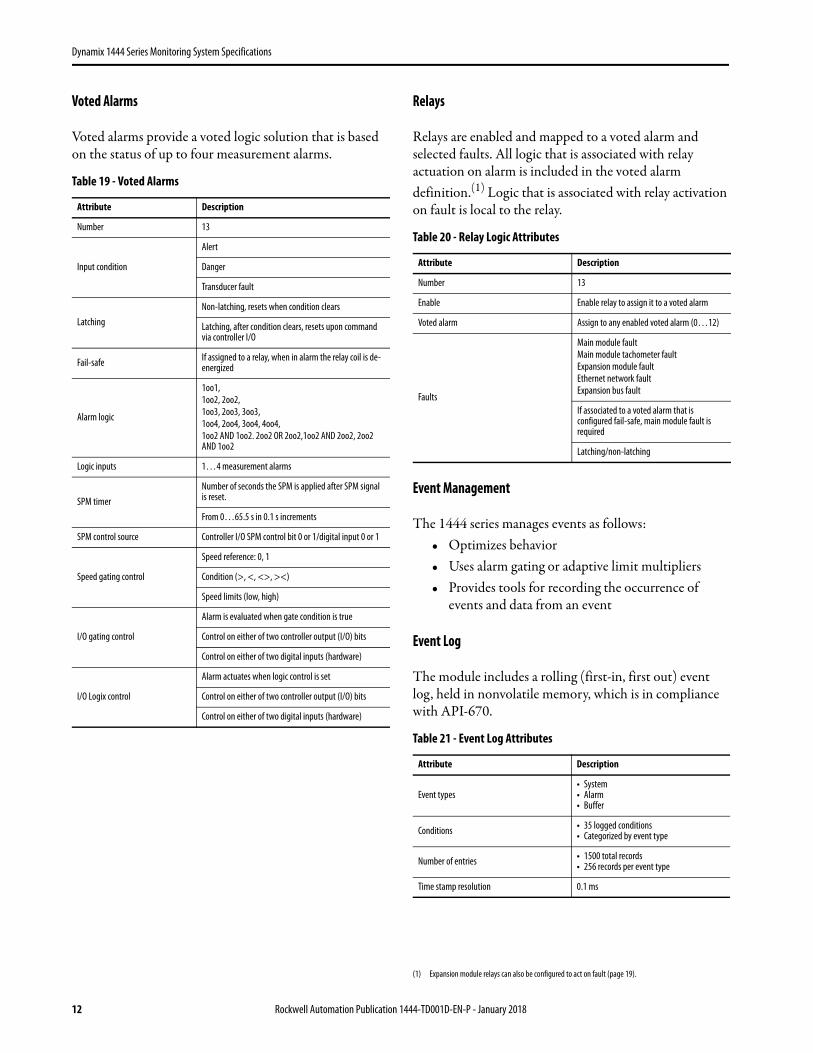
Voted Alarms
Voted alarms provide a voted logic solution that is based on the status of up to four measurement alarms.
Relays
Relays are enabled and mapped to a voted alarm and selected faults. All logic that is associated with relay actuation on alarm is included in the voted alarm definition.(1) Logic that is associated with relay activation on fault is local to the relay.
Event Management
The 1444 series manages events as follows:• Optimizes behavior• Uses alarm gating or adaptive limit multipliers• Provides tools for recording the occurrence of
events and data from an event
Event Log
The module includes a rolling (first-in, first out) event log, held in nonvolatile memory, which is in compliance with API-670.
Table 19 - Voted Alarms
Attribute Description
Number 13
Input condition
Alert
Danger
Transducer fault
LatchingNon-latching, resets when condition clears
Latching, after condition clears, resets upon command via controller I/O
Fail-safe If assigned to a relay, when in alarm the relay coil is de-energized
Alarm logic
1oo1,1oo2, 2oo2,1oo3, 2oo3, 3oo3,1oo4, 2oo4, 3oo4, 4oo4,1oo2 AND 1oo2. 2oo2 OR 2oo2,1oo2 AND 2oo2, 2oo2 AND 1oo2
Logic inputs 1…4 measurement alarms
SPM timerNumber of seconds the SPM is applied after SPM signal is reset.
From 0…65.5 s in 0.1 s increments
SPM control source Controller I/O SPM control bit 0 or 1/digital input 0 or 1
Speed gating control
Speed reference: 0, 1
Condition (>, <, <>, ><)
Speed limits (low, high)
I/O gating control
Alarm is evaluated when gate condition is true
Control on either of two controller output (I/O) bits
Control on either of two digital inputs (hardware)
I/O Logix control
Alarm actuates when logic control is set
Control on either of two controller output (I/O) bits
Control on either of two digital inputs (hardware)
(1) Expansion module relays can also be configured to act on fault (page 19).
Table 20 - Relay Logic Attributes
Attribute Description
Number 13
Enable Enable relay to assign it to a voted alarm
Voted alarm Assign to any enabled voted alarm (0…12)
Faults
Main module faultMain module tachometer faultExpansion module faultEthernet network faultExpansion bus fault
If associated to a voted alarm that is configured fail-safe, main module fault is required
Latching/non-latching
Table 21 - Event Log Attributes
Attribute Description
Event types• System• Alarm• Buffer
Conditions • 35 logged conditions• Categorized by event type
Number of entries • 1500 total records• 256 records per event type
Time stamp resolution 0.1 ms
12 Rockwell Automation Publication 1444-TD001D-EN-P - January 2018
Dynamix 1444 Series Monitoring System Specifications
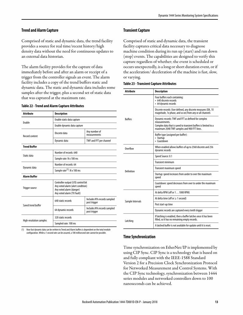
Trend and Alarm Capture
Comprised of static and dynamic data, the trend facility provides a source for real time/recent history/high density data without the need for continuous updates to an external data historian.
The alarm facility provides for the capture of data immediately before and after an alarm or receipt of a trigger from the controller signals an event. The alarm facility includes a copy of the trend buffers static and dynamic data. The static and dynamic data includes some samples after the trigger, plus a second set of static data that was captured at the maximum rate.
Transient Capture
Comprised of static and dynamic data, the transient facility captures critical data necessary to diagnose machine condition during its run up (start) and run down (stop) events. The capabilities are designed to verify this capture regardless of whether; the event is scheduled or occurs unexpectedly, is a long or short duration event, or if the acceleration/ deceleration of the machine is fast, slow, or varying.
Time Synchronization
Time synchronization on EtherNet/IP is implemented by using CIP Sync. CIP Sync is a technology that is based on and fully compliant with the IEEE-1588 Standard Version 2 for a Precision Clock Synchronization Protocol for Networked Measurement and Control Systems. With the CIP Sync technology, synchronization between 1444 series modules and networked controllers down to 100 nanoseconds can be achieved.
Table 22 - Trend and Alarm Capture Attributes
Attribute Description
EnableEnable static data capture
Enable dynamic data capture
Record contentDiscrete data Any number of
measurements
Dynamic data TWF and FFT per channel
Trend Buffer
Static dataNumber of records: 640
Sample rate: N x 100 ms
Dynamic dataNumber of records: 64
Sample rate(1): N x 100 ms
(1) How fast dynamic data can be written to Trend and Alarm buffers is dependent on the total module configuration. While a 1 second rate can be assured, a 100 millisecond rate cannot be possible.
Alarm Buffer
Trigger source
Controller output (I/O) control bitAny voted alarm (alert condition)Any voted alarm (danger)Any voted alarm (TX Fault)
Saved trend buffer640 static records Includes N% records sampled
post trigger
64 dynamic records Includes N% records sampled post trigger
High-resolution samples320 static records
Sampled rate: 100 ms
Table 23 - Transient Capture Attributes
Attribute Description
Buffers
Four buffers each containing:• 640 discrete records• 64 dynamic records
Discrete records: User defined, any discrete measures (OA, 1X magnitude, 1x phase, and so on) from any or all channels
Dynamic records: TWF and FFT as defined for complex measurements. Complex data that is saved to transient buffers is limited to a maximum 2048 TWF samples and 900 FFT lines.
Buffer type (assigned per buffer):• Startup• Coastdown
Overflow When enabled allows buffers of up to 2560 discrete and 256 dynamic records
Definition
Speed Source: 0.1
Transient minimum
Transient maximum speed
Startup: speed increases from under to over the maximum speed
Coastdown: speed decreases from over to under the maximum speed
Sample Intervals
At delta RPM (off or 1…1000 RPM)
At delta time (off or ≥ 1 second)
Post start-up time
Dynamic records are captured every tenth trigger
LatchingIf latching is enabled, then a buffer latches once it has been filled, so it has no remaining empty records.
A latched buffer is not available for update until it is reset.
Rockwell Automation Publication 1444-TD001D-EN-P - January 2018 13
Dynamix 1444 Series Monitoring System Specifications
Supported Network Topologies
The 1444 series offers two alternatives to the network solution applied. These alternatives include the common single-wire Ethernet networks and Device Level Ring networks for when a more fault-tolerant topology is required.
Single Ethernet
By using single Ethernet, as defined by IEEE 802.3, modules are connected in series on a common network. In this architecture, typically, the network is routed through adjacent modules by using one RJ45 connector as its input and the second connector as an output.
Device Level Ring
Device Level Ring (DLR) is a network topology that lets devices be connected in series, one-to-the-next, and back to the beginning, which forms a ring. Ring topologies offer a far simpler fault-tolerant network design that requires less cabling and can be installed at lower cost, while still providing a resilient, responsive solution.
Unlike typical ring solutions, DLR is deployed at the end devices, instead of the switches. So a DLR enabled device can connect directly to neighboring nodes. A ring topology at the device level greatly reduces the number of wires on the network, and the number of needed industrial Ethernet switches.
Fault Management
On detection of a fault, a Dynamix 1444-DYN04-01RA module provides indication via its status indicators, and communicates the status via controller I/O. Additionally, the single onboard relay can be configured to actuate based on any of the detected faults, see Table 24.
Controller I/O
The Dynamix 1444-DYN04-01RA module provides the following data in its controller input and output assemblies.
Input
The content of the input assembly is configurable, in module definition. At a minimum, the assembly consists of a fixed record of status information.
Additionally the input assembly can contain any number of measured values. These values include the real-time measurements that are listed in Table 12, the DC measurements in Table 13, and the continuous measurements that are listed in Table 14.
Table 24 - Main Module Fault Management Specification
Attribute Description
Expansion bus link time-out 100 ms (fixed)
Fault actions
Indication Update status indicator (Table 7)
Controller I/O Status bits on controller input table
Relay action
Select fault on any of(1)
(1) If no fault action is defined for the relay of the main module, and the voted alarm that is associated with the relay is not configured fail-safe, the relay is held in its current position until the fault condition clears.
Module*
Expansion module
Ethernet
Expansion bus
Latching/non-latching on fault
*Actuates on module fault if associated voted alarm configured fail-safe
Table 25 - Controller Input Status Information
Control Bits
Aux processor DSP processor
Trend alarm Transducer
Alarm status Channel setup
Relay status Expansion module
14 Rockwell Automation Publication 1444-TD001D-EN-P - January 2018
Dynamix 1444 Series Monitoring System Specifications
Output
The content of the output assembly is configurable, in module definition. The assembly includes various control bits, plus, when specified, speed values and alarm limits.
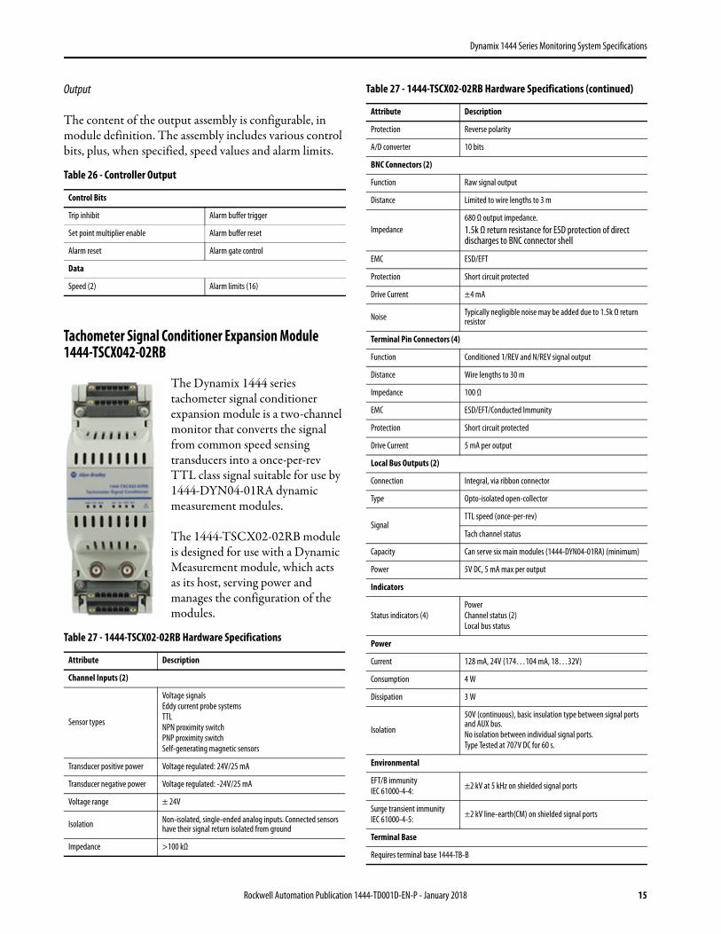
Tachometer Signal Conditioner Expansion Module 1444-TSCX042-02RB
The Dynamix 1444 series tachometer signal conditioner expansion module is a two-channel monitor that converts the signal from common speed sensing transducers into a once-per-rev TTL class signal suitable for use by 1444-DYN04-01RA dynamic measurement modules.
The 1444-TSCX02-02RB module is designed for use with a Dynamic Measurement module, which acts as its host, serving power and manages the configuration of the modules.
Table 26 - Controller Output
Control Bits
Trip inhibit Alarm buffer trigger
Set point multiplier enable Alarm buffer reset
Alarm reset Alarm gate control
Data
Speed (2) Alarm limits (16)
Table 27 - 1444-TSCX02-02RB Hardware Specifications
Attribute Description
Channel Inputs (2)
Sensor types
Voltage signalsEddy current probe systemsTTLNPN proximity switchPNP proximity switchSelf-generating magnetic sensors
Transducer positive power Voltage regulated: 24V/25 mA
Transducer negative power Voltage regulated: -24V/25 mA
Voltage range ± 24V
Isolation Non-isolated, single-ended analog inputs. Connected sensors have their signal return isolated from ground
Impedance >100 kΩ
Protection Reverse polarity
A/D converter 10 bits
BNC Connectors (2)
Function Raw signal output
Distance Limited to wire lengths to 3 m
Impedance680 Ω output impedance.1.5k Ω return resistance for ESD protection of direct discharges to BNC connector shell
EMC ESD/EFT
Protection Short circuit protected
Drive Current ±4 mA
Noise Typically negligible noise may be added due to 1.5k Ω return resistor
Terminal Pin Connectors (4)
Function Conditioned 1/REV and N/REV signal output
Distance Wire lengths to 30 m
Impedance 100 Ω
EMC ESD/EFT/Conducted Immunity
Protection Short circuit protected
Drive Current 5 mA per output
Local Bus Outputs (2)
Connection Integral, via ribbon connector
Type Opto-isolated open-collector
SignalTTL speed (once-per-rev)
Tach channel status
Capacity Can serve six main modules (1444-DYN04-01RA) (minimum)
Power 5V DC, 5 mA max per output
Indicators
Status indicators (4)PowerChannel status (2)Local bus status
Power
Current 128 mA, 24V (174…104 mA, 18…32V)
Consumption 4 W
Dissipation 3 W
Isolation
50V (continuous), basic insulation type between signal ports and AUX bus.No isolation between individual signal ports.Type Tested at 707V DC for 60 s.
Environmental
EFT/B immunityIEC 61000-4-4: ±2 kV at 5 kHz on shielded signal ports
Surge transient immunityIEC 61000-4-5: ±2 kV line-earth(CM) on shielded signal ports
Terminal Base
Requires terminal base 1444-TB-B
Table 27 - 1444-TSCX02-02RB Hardware Specifications (continued)
Attribute Description
Rockwell Automation Publication 1444-TD001D-EN-P - January 2018 15
Dynamix 1444 Series Monitoring System Specifications
Functional Specifications
Host Module Dependence
The tachometer signal conditioner module commonly serves speed signals to main modules other than its host. So, unlike other expansion modules, and except for configuration services, the 1444-TSCX02-02RB operates independently of its host module. Therefore, once configured, the tachometer signal conditioner module continuously serves TTL speed signals regardless of the state or availability of its host module or local bus.
Fault Management
On failure of self-test or on communication link failure, the tachometer signal conditioner module notifies its host module, if possible, and signals the condition via status indicators.
Removable Plug Connector Sets
ModuleSpring 1444-TSC-RPC-SPR-01
Screw 1444-TSC-RPC-SCW-01
Terminal baseSpring 1444-TBB-RPC-SPR-01
Screw 1444-TBB-RPC-SCW-01
Dimensions
Definition
H: height above DIN rail
W: width along DIN rail
D: depth across DIN rail
Without terminal base (H x W x D) 65 x 54 x 154 mm (2.56 x 2.13 x 6.06 in.)
With terminal base (H x W x D) 96 x 54 x 158 mm (3.78 x 2.13 x 6.22 in.)
Weight
Without terminal base 0.16 kg (0.35 lb)
Table 27 - 1444-TSCX02-02RB Hardware Specifications (continued)
Attribute Description
Table 28 - TSC Module Functional Specification
Attribute Description
Trigger
Eddy Current Probes
Auto Threshold(1)
(1) Auto Threshold requires the 1444-TSCX02-02RB/B (series B) hardware.
Minimum signal amplitude: 1.5 volts peak to peak
Minimum freq: 6 cpm (0.1 Hz)
Minimum pulse width: 25 μs
Manual ThresholdLevel: -32…+32V
Minimum freq: 1 cpm (0.017 Hz)
Self-generating Magnetic Pickups
Auto Threshold(1)
Threshold: 0.4V
Hysteresis: 0.8V
Minimum freq: 12 cpm (0.2 Hz)
Manual Threshold Level: -32…+32V
Minimum freq: 1 cpm (0.017 Hz)
TTL, NPN, and PNP proximity switch
Auto Threshold Fixed trigger level dependent on sensor type
Manual Threshold Not available
Accuracy ± 3° of speed input for 1/rev up to 20 kHz
Error
0.0167…4 Hz: ± 0.0033 Hz4…200 Hz: ± 0.033 Hz200…340 Hz: ± 0.083 Hz340…2000 Hz: ± 0.333 Hz2000…6000 Hz: ± 1.0 Hz6000…20,000 Hz: ± 2.67 Hz
Error
1…240 RPM: ± 0.2 RPM240…12k RPM: ±2.0 RPM12k…20.4k RPM: ±5.0 RPM20.4k…120k RPM: ±20 RPM120k…360k RPM: ±60 RPM360k…1,200k RPM: ±160 RPM
Fault Detection Communication link time-out: 1 second (fixed)
Fault Action Update Module Status indicator
16 Rockwell Automation Publication 1444-TD001D-EN-P - January 2018
Dynamix 1444 Series Monitoring System Specifications
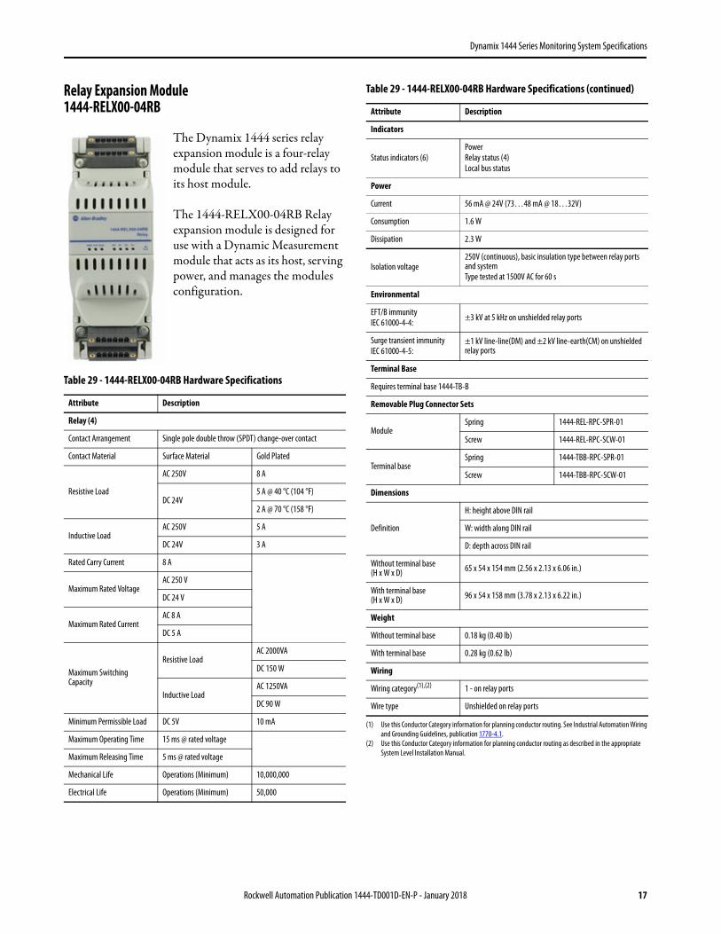
Relay Expansion Module 1444-RELX00-04RB
The Dynamix 1444 series relay expansion module is a four-relay module that serves to add relays to its host module.
The 1444-RELX00-04RB Relay expansion module is designed for use with a Dynamic Measurement module that acts as its host, serving power, and manages the modules configuration.
Table 29 - 1444-RELX00-04RB Hardware Specifications
Attribute Description
Relay (4)
Contact Arrangement Single pole double throw (SPDT) change-over contact
Contact Material Surface Material Gold Plated
Resistive Load
AC 250V 8 A
DC 24V5 A @ 40 °C (104 °F)
2 A @ 70 °C (158 °F)
Inductive LoadAC 250V 5 A
DC 24V 3 A
Rated Carry Current 8 A
Maximum Rated VoltageAC 250 V
DC 24 V
Maximum Rated CurrentAC 8 A
DC 5 A
Maximum Switching Capacity
Resistive LoadAC 2000VA
DC 150 W
Inductive LoadAC 1250VA
DC 90 W
Minimum Permissible Load DC 5V 10 mA
Maximum Operating Time 15 ms @ rated voltage
Maximum Releasing Time 5 ms @ rated voltage
Mechanical Life Operations (Minimum) 10,000,000
Electrical Life Operations (Minimum) 50,000
Indicators
Status indicators (6)PowerRelay status (4)Local bus status
Power
Current 56 mA @ 24V (73…48 mA @ 18…32V)
Consumption 1.6 W
Dissipation 2.3 W
Isolation voltage250V (continuous), basic insulation type between relay ports and systemType tested at 1500V AC for 60 s
Environmental
EFT/B immunityIEC 61000-4-4: ±3 kV at 5 kHz on unshielded relay ports
Surge transient immunityIEC 61000-4-5:
±1 kV line-line(DM) and ±2 kV line-earth(CM) on unshielded relay ports
Terminal Base
Requires terminal base 1444-TB-B
Removable Plug Connector Sets
ModuleSpring 1444-REL-RPC-SPR-01
Screw 1444-REL-RPC-SCW-01
Terminal baseSpring 1444-TBB-RPC-SPR-01
Screw 1444-TBB-RPC-SCW-01
Dimensions
Definition
H: height above DIN rail
W: width along DIN rail
D: depth across DIN rail
Without terminal base (H x W x D) 65 x 54 x 154 mm (2.56 x 2.13 x 6.06 in.)
With terminal base (H x W x D) 96 x 54 x 158 mm (3.78 x 2.13 x 6.22 in.)
Weight
Without terminal base 0.18 kg (0.40 lb)
With terminal base 0.28 kg (0.62 lb)
Wiring
Wiring category(1),(2) 1 - on relay ports
Wire type Unshielded on relay ports
(1) Use this Conductor Category information for planning conductor routing. See Industrial Automation Wiring and Grounding Guidelines, publication 1770-4.1.
(2) Use this Conductor Category information for planning conductor routing as described in the appropriate System Level Installation Manual.
Table 29 - 1444-RELX00-04RB Hardware Specifications (continued)
Attribute Description
Rockwell Automation Publication 1444-TD001D-EN-P - January 2018 17
Dynamix 1444 Series Monitoring System Specifications
Functional Specifications
Host Module Dependence
The Relay expansion module is designed to act as an extension of its host module. The operation of the 1444-RELX00-04RB module is dependent on the availability of its host.
A handshake communiqué between the relay expansion module and its host is executed continuously to verify communication and each modules operation. Failure of the Heartbeat™ constitutes a Link Failure condition on the relay module and a Module Fault on the main module.
Double-Pole Relays
When API-670 compliance or other applications require use of double-pole, double-throw (DPDT) relays, two expansion module relays can be paired.
Fault Management
If a Relay expansion module fails self-tests (module fault) or detects a Link Failure, it actuates any relays that are configured as ‘Fail-Safe’ in the referenced voted alarm definition. Also, any relays that are configured to actuate on expansion bus fault.
Upon re-establishing communication to a relay module, a host module verifies the position of all relays, and commands each to be repositioned based on current alarm status and latching definition.
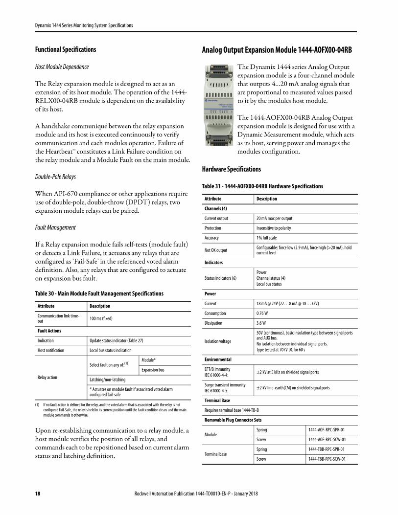
Analog Output Expansion Module 1444-AOFX00-04RB
The Dynamix 1444 series Analog Output expansion module is a four-channel module that outputs 4…20 mA analog signals that are proportional to measured values passed to it by the modules host module.
The 1444-AOFX00-04RB Analog Output expansion module is designed for use with a Dynamic Measurement module, which acts as its host, serving power and manages the modules configuration.
Hardware Specifications
Table 30 - Main Module Fault Management Specifications
Attribute Description
Communication link time-out 100 ms (fixed)
Fault Actions
Indication Update status indicator (Table 27)
Host notification Local bus status indication
Relay action
Select fault on any of:(1)
(1) If no fault action is defined for the relay, and the voted alarm that is associated with the relay is not configured Fail-Safe, the relay is held in its current position until the fault condition clears and the main module commands it otherwise.
Module*
Expansion bus
Latching/non-latching
* Actuates on module fault if associated voted alarm configured fail-safe
Table 31 - 1444-AOFX00-04RB Hardware Specifications
Attribute Description
Channels (4)
Current output 20 mA max per output
Protection Insensitive to polarity
Accuracy 1% full scale
Not OK output Configurable: force low (2.9 mA), force high (>20 mA), hold current level
Indicators
Status indicators (6)PowerChannel status (4)Local bus status
Power
Current 18 mA @ 24V (22…8 mA @ 18…32V)
Consumption 0.76 W
Dissipation 3.6 W
Isolation voltage
50V (continuous), basic insulation type between signal ports and AUX bus.No isolation between individual signal ports.Type tested at 707V DC for 60 s
Environmental
EFT/B immunityIEC 61000-4-4: ±2 kV at 5 kHz on shielded signal ports
Surge transient immunityIEC 61000-4-5: ±2 kV line-earth(CM) on shielded signal ports
Terminal Base
Requires terminal base 1444-TB-B
Removable Plug Connector Sets
ModuleSpring 1444-AOF-RPC-SPR-01
Screw 1444-AOF-RPC-SCW-01
Terminal baseSpring 1444-TBB-RPC-SPR-01
Screw 1444-TBB-RPC-SCW-01
18 Rockwell Automation Publication 1444-TD001D-EN-P - January 2018
Dynamix 1444 Series Monitoring System Specifications
Functional Specification
The analog output expansion module is designed to act as an extension of its host module. So therefore, operation of the 1444-AOFX00-04RB module is dependent on the availability of its host.
Fault Management
On failure of self-test or on communication link failure, if possible, the 4…20 mA Output module notifies its host module, signals the condition via status indicators and drives its outputs as specified by configuration, see Table 32.
Terminal Bases
Each Dynamix module is installed in a terminal base that, when linked together, serve as the backplane of a 1444 series system.
Besides providing connections for common or ‘dirty’ wiring, the terminal bases provide two key capabilities for the system.
Addressing
The MAC ID can be set using DHCP/BOOTP tools, or as 192.168.0.xxx, where the last octet of the address (xxx) is specified by a switch on the terminal base. The terminal base switch provides a portable, physical relationship that makes sure that modules installed are at the address set on the base rather than whatever can be in the memory of the module.
The expansion modules terminal base, the 1444-TB-B, also includes an address switch. However, in this case the switch is only used when a relay module is installed. In that case, the relay module must be set as 1, 2, or 3. Addressing for the tachometer signal conditioner expansion module and the analog output expansion module is automatic so does not use the switch.
Local Bus
Each terminal base includes the circuitry and connectors necessary to extend the local bus. A ribbon cable is included that is of a length suitable for connecting two adjacent terminal bases.(1)
The local bus is not interrupted when a module is removed. Removal or failure of any module does not affect tachometer signals, power, and local bus communication.
Dimensions
Definition
H: height above DIN rail
W: width along DIN rail
D: depth across DIN rail
Without terminal base (H x W x D) 65 x 54 x 154 mm (2.56 x 2.13 x 6.06 in.)
With terminal base (H x W x D) 96 x 54 x 158 mm (3.78 x 2.13 x 6.22 in.)
Weight
Without terminal base 0.14 kg (0.31 lb)
With terminal base 0.24 kg (0.53 lb)
Wiring
Wiring category(1),(2) 2 - on signal ports
Wire type Shielded on all signal ports
(1) Use this Conductor Category information for planning conductor routing. See Industrial Automation Wiring and Grounding Guidelines, publication 1770-4.1.
(2) Use this Conductor Category information for planning conductor routing as described in the appropriate System Level Installation Manual
Table 32 - Analog Output Module Functional Specification
Attribute Description
Communication time-out 1 second (fixed)
Fault Actions
Indication Update Module Status indicator
Output behavior on fault options
No action
Force low (<4 mA)
Force high (>20 mA)
Table 31 - 1444-AOFX00-04RB Hardware Specifications (continued)
Attribute Description
(1) Longer cables are available for use when jumping modules on adjacent DIN rails or when locating modules in other areas of a cabinet.
Rockwell Automation Publication 1444-TD001D-EN-P - January 2018 19
Dynamix 1444 Series Monitoring System Specifications
Terminal Base 1444-TB-A
Terminal Base 1444-TB-B
All 1444 series expansion modules work with the same terminal base, 1444-TB-B.
Configuration Software
The Rockwell Automation Logix controllers serve the configuration of 1444 series modules. After a powerup, or whenever a configuration is changed, the controller automatically pushes the configuration to the module.
The Add-on Profile is a program that executes within the Studio 5000 Engineering and Design Environment™. As part of Rockwell Automation Integrated Architecture, and by using a Studio 5000 Add-on Profile, the 1444 series configuration tools and processes are consistent with all other products that live within the Studio 5000 environment. This consistency makes sure that you spend less time learning the tools and more time defining their implementation.
The Dynamix 1444 Series is supported in Studio 5000 V24+ and in specific versions of V20 (contact Rockwell Automation regards availability of V20 solutions). Redundancy requires controller firmware V24.51+.
Condition Monitoring Software
Support for the Dynamix 1444 Series is included in our Emonitor® CMS (Condition Monitoring Software).
Table 33 - 1444-TB-A Specifications
Attribute Description
Module 1444-DYN04-01RA
DIN rail 35 x 7.5 mm according to EN 50022, BS 5584, or DIN 46277-6
Voltage range, input
North American:18...32V, max 8 A,Limited Voltage Source
ATEX/IECEx:18...32V, max 8 A,SELV/PELV Source
Voltage range, auxiliary bus 18…32V, 1 A max
Physical
Dimensions include module
Dimensions (H x W x D) 116 x 103.5 x 155.5 mm (4.57 x 4.07 x 6.12 in.)
Weight 204.12 g (0.45 lb)
Removable Plug Connector Sets
Spring clamp 1444-TBA-RPC-SPR-01
Screw clamp 1444-TBA-RPC-SCW-01
Table 34 - 1444-TB-B Specifications
Attribute Description
Modules
1444-TSCX02-02RB
1444-RELX00-04RB
1444-AOFX00-04RB
DIN rail 35 mm x 7.5 mm according to EN 50022, BS 5584, or DIN 46277-6
Voltage range, input
North American:18...32V, max 8 A,Limited Voltage Source
ATEX/IECEx:18...32V, max 8 A,SELV/PELV Source
Voltage range, auxiliary bus 18…32V, 1 A max
Physical
Dimensions include module
Dimensions (H x W x D) 90.2 x 54.7 x 155.5 mm (3.55 x 2.15 x 6.12 in.)
Weight 113.40 g (0.25 lb)
Removable Plug Connector Sets
Spring clamp 1444-TBB-RPC-SPR-01
Screw clamp 1444-TBB-RPC-SCW-01
Table 35 - Controller Memory Requirements
Module Number kB (apx)
1 50
2…N 15 ea
Catalog Number Description
9309-CMS00ENE Emonitor Condition Monitoring Software
Table 34 - 1444-TB-B Specifications (continued)
Attribute Description
20 Rockwell Automation Publication 1444-TD001D-EN-P - January 2018
Dynamix 1444 Series Monitoring System Specifications
CMS supports the 1444 Series through a suite of three new utilities including:
*Real-Time Analyzer (RTA). The RTA is a freely deployed application that provides real-time visualization and analysis of TWF and FFT data read from any 1444 series dynamic measurement module. The RTA is intended to aid system installation and configuration, and to provide a simple tool to view current live data from any module, from anywhere, whenever required. The RTA does not require Emonitor to be installed on the personal computer, is not licensed separately, and requires only RSLinx® Lite to access network devices.
* Emonitor Extraction Manager (EEM). The EEM provides users a simple environment for mapping data from 1444 Series modules to an Emonitor database, and to define schedules for routine data acquisition. The output of the EEM is the input to the DDM.
* Data Download Manager (DDM). The DDM is a utility, which runs as a Windows Service, which executes data acquisition from any number of Dynamix modules following any number of schedules as defined by the EEM. Once sampled the DDM writes the data to standard Emonitor Unload Files.
Accessories
Available accessories include terminal plug connectors, extended interconnect cables, and a wide selection of industrial Ethernet cable solutions.
Ethernet Cable
The 1444 series are designed to operate in harsh industrial environments and possibly near electrically noisy or high-voltage devices and wiring.
When a Dynamix system is fully enclosed in a shielded environment (cabinet, metal conduit), unshielded media can be used. Otherwise, shielded, category Cat 5e (or 6), class D (or E) cables are recommended.
Ethernet cable accessories are provided by Allen-Bradley® 1585 Series Ethernet Media products.
Consult publications 1585-BR001 and M117-CA506 for further guidance in selection of a cable solution.(1)(2)
Removable Plug Connectors
1444 series modules are fitted with plug style connectors. The connectors let users wire the connections before installing the terminal base or module. The connectors also let you select between screw clamp and spring cage style terminal connector solutions as necessary for each application. As the modules and terminal bases are not shipped with included plug connectors, you must purchase the necessary connectors as listed in Table 36 and Table 37.
See Table 36 for Spring-style connectors or Table 37 for Screw-style connectors.
(1) Only Straight connectors are recommended for use with 1444 series modules.(2) Be sure that the temperature rating of a selected cable is applicable to the environments that the 1444
series can be installed in, up to 70 °C (158 °F).
Table 36 - Spring-style Removable Plug Connectors
Spring ConnectorsModule Cat. No.1444-DYN04-01RA 1444-DYN-RPC-SPR-01
1444-TSCX02-02RB 1444-TSC-RPC-SPR-01
1444-RELX00-04RB 1444-REL-RPC-SPR-01
1444-AOFX00-04RB 1444-AOF-RPC-SPR-01
Terminal Base Cat. No.1444-TB-A 1444-TBA-RPC-SPR-01
1444-TB-B 1444-TBB-RPC-SPR-01
Table 37 - Screw-style Removable Plug Connectors
Screw ConnectorsModule Cat. No.1444-DYN04-01RA 1444-DYN-RPC-SCW-01
1444-TSCX02-02RB 1444-TSC-RPC-SCW-01
1444-RELX00-04RB 1444-REL-RPC-SCW-01
1444-AOFX00-04RB 1444-AOF-RPC-SCW-01
Terminal Base Cat. No.1444-TB-A 1444-TBA-RPC-SCW-01
1444-TB-B 1444-TBB-RPC-SCW-01
Rockwell Automation Publication 1444-TD001D-EN-P - January 2018 21
Dynamix 1444 Series Monitoring System Specifications
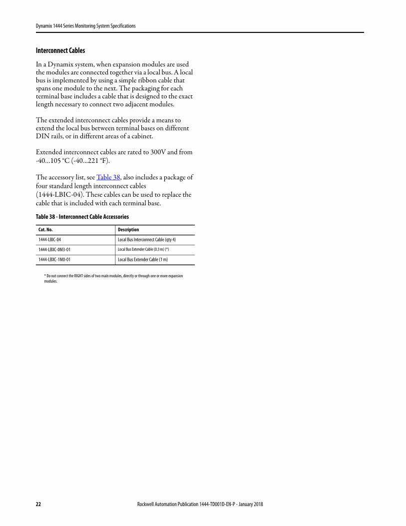
Interconnect Cables
In a Dynamix system, when expansion modules are used the modules are connected together via a local bus. A local bus is implemented by using a simple ribbon cable that spans one module to the next. The packaging for each terminal base includes a cable that is designed to the exact length necessary to connect two adjacent modules.
The extended interconnect cables provide a means to extend the local bus between terminal bases on different DIN rails, or in different areas of a cabinet.
Extended interconnect cables are rated to 300V and from -40…105 °C (-40…221 °F).
The accessory list, see Table 38, also includes a package of four standard length interconnect cables (1444-LBIC-04). These cables can be used to replace the cable that is included with each terminal base.
* Do not connect the RIGHT sides of two main modules, directly or through one or more expansion modules.
Table 38 - Interconnect Cable Accessories
Cat. No. Description
1444-LBIC-04 Local Bus Interconnect Cable (qty 4)
1444-LBXC-0M3-01 Local Bus Extender Cable (0.3 m) (*)
1444-LBXC-1M0-01 Local Bus Extender Cable (1 m)
22 Rockwell Automation Publication 1444-TD001D-EN-P - January 2018

Dynamix 1444 Series Monitoring System Specifications
Notes:
Rockwell Automation Publication 1444-TD001D-EN-P - January 2018 23
Allen-Bradley, Dynamix, Integrated Architecture, Logix5000, Rockwell Software, Rockwell Automation, Studio 5000 Engineering and Design Environment, and LISTEN. THINK. SOLVE are trademarks of Rockwell Automation, Inc.Trademarks not belonging to Rockwell Automation are property of their respective companies.
Publication 1444-TD001D-EN-P - January 2018
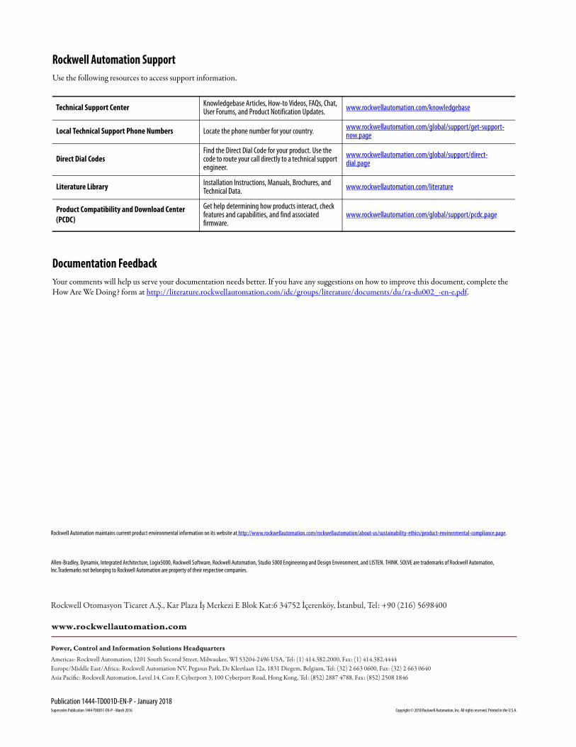
Rockwell Automation SupportUse the following resources to access support information.
Documentation FeedbackYour comments will help us serve your documentation needs better. If you have any suggestions on how to improve this document, complete the How Are We Doing? form at http://literature.rockwellautomation.com/idc/groups/literature/documents/du/ra-du002_-en-e.pdf.
Technical Support Center Knowledgebase Articles, How-to Videos, FAQs, Chat, User Forums, and Product Notification Updates. www.rockwellautomation.com/knowledgebase
Local Technical Support Phone Numbers Locate the phone number for your country. www.rockwellautomation.com/global/support/get-support-now.page
Direct Dial CodesFind the Direct Dial Code for your product. Use the code to route your call directly to a technical support engineer.
www.rockwellautomation.com/global/support/direct-dial.page
Literature Library Installation Instructions, Manuals, Brochures, and Technical Data. www.rockwellautomation.com/literature
Product Compatibility and Download Center (PCDC)
Get help determining how products interact, check features and capabilities, and find associated firmware.
www.rockwellautomation.com/global/support/pcdc.page
Rockwell Otomasyon Ticaret A.Ş., Kar Plaza İş Merkezi E Blok Kat:6 34752 İçerenköy, İstanbul, Tel: +90 (216) 5698400
Rockwell Automation maintains current product environmental information on its website at http://www.rockwellautomation.com/rockwellautomation/about-us/sustainability-ethics/product-environmental-compliance.page.
Supersedes Publication 1444-TD001C-EN-P - March 2016 Copyright © 2018 Rockwell Automation, Inc. All rights reserved. Printed in the U.S.A.