Embed Size (px)
Citation preview
www.dsiamerica.com
DYWI® Drill System
Installation Instructions & Technical Notes
Railroad Grade Separation – Reno ReTRAC Project, Reno NV
2
DYWI® Drill System
Contents Page
Section Content Page
1. INTRODUCTION ............................................................................................................................................ 4 2. DYWI
® Drill Bar - Installation Examples ......................................................................................................... 5
3. APPLICATIONS ............................................................................................................................................. 6
3.1. Soil Nails ........................................................................................................................................... 6 3.2. Double Corrosion Anchors ................................................................................................................ 6 3.3. Micro Piles ......................................................................................................................................... 7 3.4. Spiles and Rock Bolts ....................................................................................................................... 7
4. LIFESPAN – Temporary and Permanent Applications .................................................................................. 8 5. DYWI
® DRILL BAR TECHNICAL DATA ........................................................................................................ 8
6. DRILL BITS .................................................................................................................................................... 9
6.1. Drill Bit Adaptor Sleeves ................................................................................................................. 12 6.2. Drill Hole Enlargement .................................................................................................................... 12
7. COUPLERS .................................................................................................................................................. 13
7.1. Seating and Sealing of Bars within Couplers .................................................................................. 13 7.2. Hammer Couplers. Reducing Couplers .......................................................................................... 13
8. ACCESSORIES ........................................................................................................................................... 14
8.1. Hex Nuts, Splice Couplers ............................................................................................................. 14 8.2. Washers .......................................................................................................................................... 14 8.3. Bearing Plates ................................................................................................................................. 14 8.4. Free Stressing Length ..................................................................................................................... 14 8.5. Drill Hole Spacers............................................................................................................................ 14
9. INSTALLATION EQUIPMENT ..................................................................................................................... 15
9.1. Drill Rigs .......................................................................................................................................... 15 9.2. Top Drive ......................................................................................................................................... 15 9.3. Hand Held Rock Drills ..................................................................................................................... 16
3
DYWI® Drill System
Contents Page
Section Content Page
10. GROUT SWIVELS ....................................................................................................................................... 16 10.1. Component Parts and Assembly ................................................................................................. 17 10.2. Selection of Grout Swivels for Drill Rigs ...................................................................................... 18 10.3. High Pressure Injection Adaptors 0-250 psi ................................................................................ 18 10.4. Locator Frame ............................................................................................................................. 19 10.5. Grout Swivel for Hand Held Equipment ...................................................................................... 20 10.6. Hex Shank Adaptor for Hand Held Equipment............................................................................ 20
11. INSTALLATION ............................................................................................................................................ 21
11.1. Simultaneous Drilling and Grouting ............................................................................................. 21 11.2. Water Flush Drilling Followed By Grouting ................................................................................. 21 11.3. Air Flush Drilling Followed By Grouting ....................................................................................... 22 11.4. Installation Rates ......................................................................................................................... 22 11.5. Limits Of System ......................................................................................................................... 22
11.5.1. Clay .............................................................................................................................. 22 11.5.2 Rock ............................................................................................................................. 23 11.5.3. Concrete ....................................................................................................................... 23
12. GROUTING .................................................................................................................................................. 23
12.1. Typical Grout Mixes ..................................................................................................................... 23 12.2. Grout Pumps ............................................................................................................................... 23 12.3. Grout Consumption ..................................................................................................................... 24 12.4. Grouting Pressures ..................................................................................................................... 24 12.5. Post Grouting .............................................................................................................................. 24 12.6. Specialist Components/Plant ...................................................................................................... 24 12.7. Post Grouting Procedure ............................................................................................................. 25
13. CORROSION PROTECTION ...................................................................................................................... 25
13.1. Permanent Ground Anchors ....................................................................................................... 26 13.2. Permanent Soil Nails or Rock Bolts ............................................................................................ 26 13.3. Permanent Micro Piles ................................................................................................................ 26 13.4. Limitations of Drill Hole Grout as a Corrosion Protection Barrier ................................................ 26 13.5. Grout Encapsulation, Grout Cover .............................................................................................. 27 13.6. Crack Width Control of Grout ...................................................................................................... 27 13.7. Galvanizing or Epoxy Coating of DYWI
® Drill Bar ....................................................................... 27
13.8. Sacrificial Corrosion Assessment ................................................................................................ 27
14. STRESSING AND TESTING ....................................................................................................................... 28 14.1. Preparation of Testing Surfaces .................................................................................................. 28 14.2. Perpendicular Bearing Surface -Soil Nail Testing on Slopes ...................................................... 28 14.3. Pocket Dimensions ...................................................................................................................... 29 14.4. Alignment Loads .......................................................................................................................... 29 14.5. Stressing and Testing Equipment ............................................................................................... 29 14.6. Exposed Bar Requirement for Jack Connection ......................................................................... 29 14.7. Testing ......................................................................................................................................... 30 14.8. Proof Test .................................................................................................................................... 30 14.9. Load Increments .......................................................................................................................... 30 14.10. Load and Extension Readings .................................................................................................... 30 14.11. Pull Out Performance .................................................................................................................. 30
4
1. INTRODUCTION
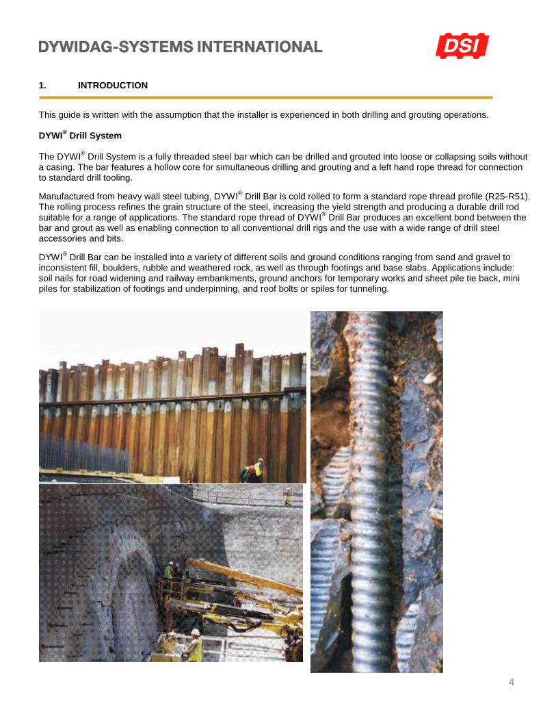
This guide is written with the assumption that the installer is experienced in both drilling and grouting operations. DYWI
® Drill System
The DYWI
® Drill System is a fully threaded steel bar which can be drilled and grouted into loose or collapsing soils without
a casing. The bar features a hollow core for simultaneous drilling and grouting and a left hand rope thread for connection to standard drill tooling.
Manufactured from heavy wall steel tubing, DYWI® Drill Bar is cold rolled to form a standard rope thread profile (R25-R51).
The rolling process refines the grain structure of the steel, increasing the yield strength and producing a durable drill rod suitable for a range of applications. The standard rope thread of DYWI
® Drill Bar produces an excellent bond between the
bar and grout as well as enabling connection to all conventional drill rigs and the use with a wide range of drill steel accessories and bits.
DYWI® Drill Bar can be installed into a variety of different soils and ground conditions ranging from sand and gravel to
inconsistent fill, boulders, rubble and weathered rock, as well as through footings and base slabs. Applications include: soil nails for road widening and railway embankments, ground anchors for temporary works and sheet pile tie back, mini piles for stabilization of footings and underpinning, and roof bolts or spiles for tunneling.

5
2. DYWI
® DRILL BAR - Installation Examples
1. Drilling with a tungsten carbide button drill bit.
3. Galvanized soil nails securing an erosion control geomat, to resist soil slip. The grass on the slope was re-established by seeding the geomat.
5. Underpinning of augered columns. The cast in situ columns was used to ensure lateral stability at the top of the micropile.
2. Temporary anchors for sheet pile tie back. Waling beams and anchors were installed at two levels, to provide increased support to the wall.
4. Soil nails installed into sand. Simultaneous drilling and grouting offers increased productivity and is beneficial to placement of the grout.
6. Testing of soil nails. Displacement is measured by a dial gauge (mounted independently), with load measured through a pressure gauge on the pump.
6
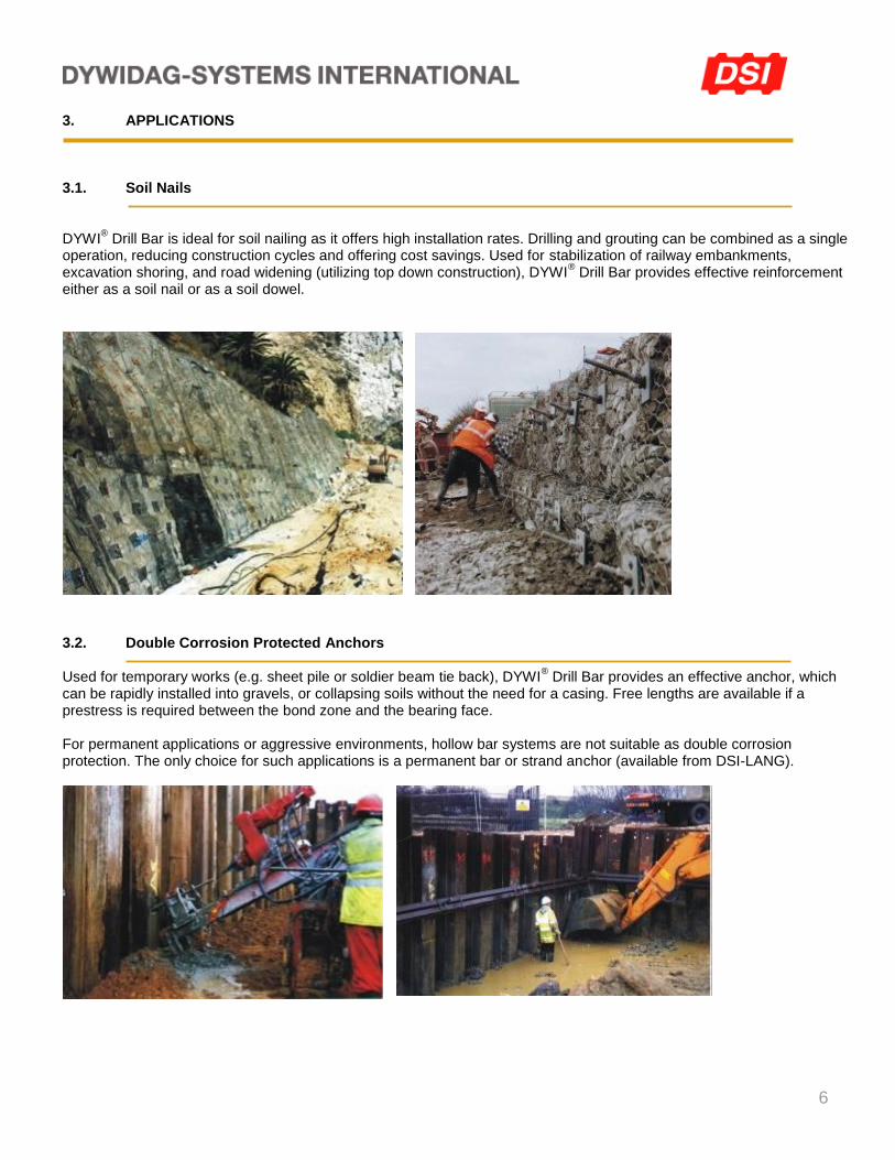
3. APPLICATIONS 3.1. Soil Nails DYWI
® Drill Bar is ideal for soil nailing as it offers high installation rates. Drilling and grouting can be combined as a single
operation, reducing construction cycles and offering cost savings. Used for stabilization of railway embankments, excavation shoring, and road widening (utilizing top down construction), DYWI
® Drill Bar provides effective reinforcement
either as a soil nail or as a soil dowel.
3.2. Double Corrosion Protected Anchors Used for temporary works (e.g. sheet pile or soldier beam tie back), DYWI
® Drill Bar provides an effective anchor, which
can be rapidly installed into gravels, or collapsing soils without the need for a casing. Free lengths are available if a prestress is required between the bond zone and the bearing face. For permanent applications or aggressive environments, hollow bar systems are not suitable as double corrosion protection. The only choice for such applications is a permanent bar or strand anchor (available from DSI-LANG).
7
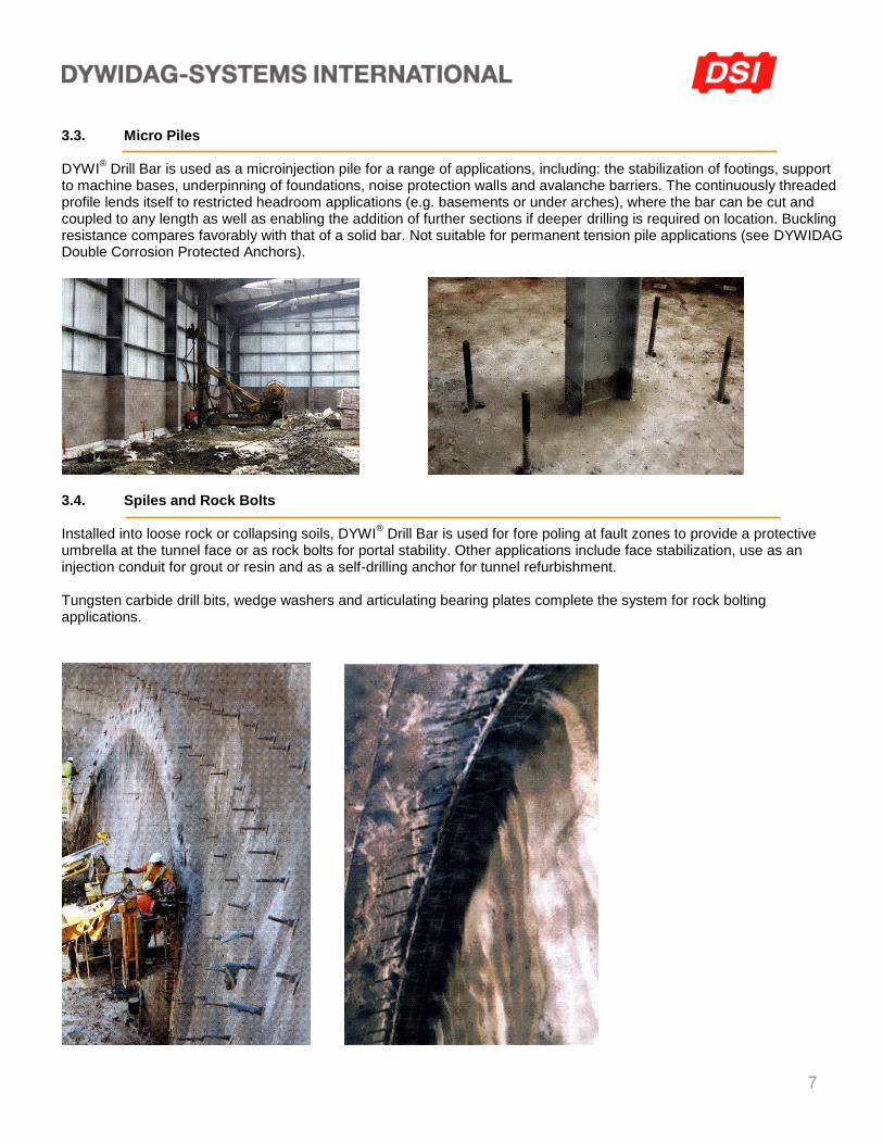
3.3. Micro Piles DYWI
® Drill Bar is used as a microinjection pile for a range of applications, including: the stabilization of footings, support
to machine bases, underpinning of foundations, noise protection walls and avalanche barriers. The continuously threaded profile lends itself to restricted headroom applications (e.g. basements or under arches), where the bar can be cut and coupled to any length as well as enabling the addition of further sections if deeper drilling is required on location. Buckling resistance compares favorably with that of a solid bar. Not suitable for permanent tension pile applications (see DYWIDAG Double Corrosion Protected Anchors).
3.4. Spiles and Rock Bolts Installed into loose rock or collapsing soils, DYWI
® Drill Bar is used for fore poling at fault zones to provide a protective
umbrella at the tunnel face or as rock bolts for portal stability. Other applications include face stabilization, use as an injection conduit for grout or resin and as a self-drilling anchor for tunnel refurbishment. Tungsten carbide drill bits, wedge washers and articulating bearing plates complete the system for rock bolting applications.
8
4. LIFESPAN Temporary Applications By definition, temporary applications cover a lifespan of up to two years. Self-drilling DYWI
® Drill systems are considered
suitable for a range of temporary applications, provided that the environment is not too aggressive. Permanent Applications For life spans greater than two years or where the environment is classified as aggressive, the use of hollow bars needs to be carefully assessed on the following basis:
Soil Nails - suitable for low risk applications in mildly aggressive environments.
Ground Anchors - not suitable.
Micro-Piles - suitable for certain applications in compression, but not constant tension. Note: See Section 13 Corrosion Protection 5. DYWI
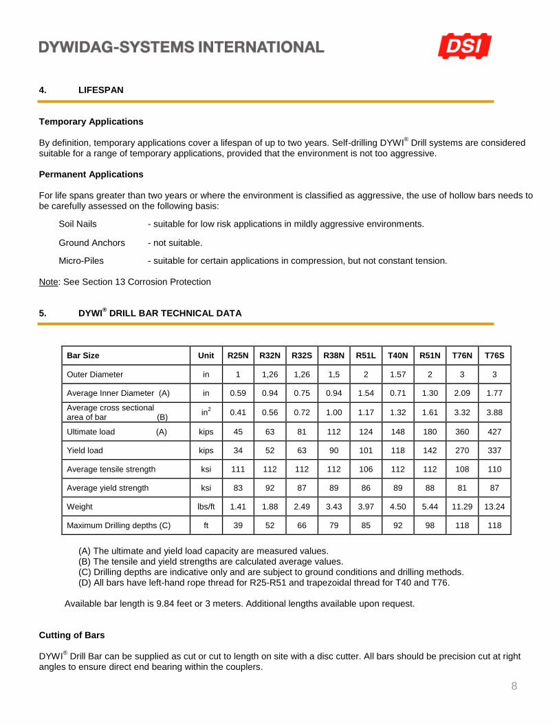
® DRILL BAR TECHNICAL DATA
(A) The ultimate and yield load capacity are measured values.
(B) The tensile and yield strengths are calculated average values. (C) Drilling depths are indicative only and are subject to ground conditions and drilling methods. (D) All bars have left-hand rope thread for R25-R51 and trapezoidal thread for T40 and T76.
Available bar length is 9.84 feet or 3 meters. Additional lengths available upon request.
Cutting of Bars DYWI
® Drill Bar can be supplied as cut or cut to length on site with a disc cutter. All bars should be precision cut at right
angles to ensure direct end bearing within the couplers.
Bar Size Unit R25N R32N R32S R38N R51L T40N R51N T76N T76S
Outer Diameter in 1 1,26 1,26 1,5 2 1.57 2 3 3
Average Inner Diameter (A) in 0.59 0.94 0.75 0.94 1.54 0.71 1.30 2.09 1.77
Average cross sectional area of bar (B)
in2 0.41 0.56 0.72 1.00 1.17 1.32 1.61 3.32 3.88
Ultimate load (A) kips 45 63 81 112 124 148 180 360 427
Yield load kips 34 52 63 90 101 118 142 270 337
Average tensile strength ksi 111 112 112 112 106 112 112 108 110
Average yield strength ksi 83 92 87 89 86 89 88 81 87
Weight lbs/ft 1.41 1.88 2.49 3.43 3.97 4.50 5.44 11.29 13.24
Maximum Drilling depths (C) ft 39 52 66 79 85 92 98 118 118
9
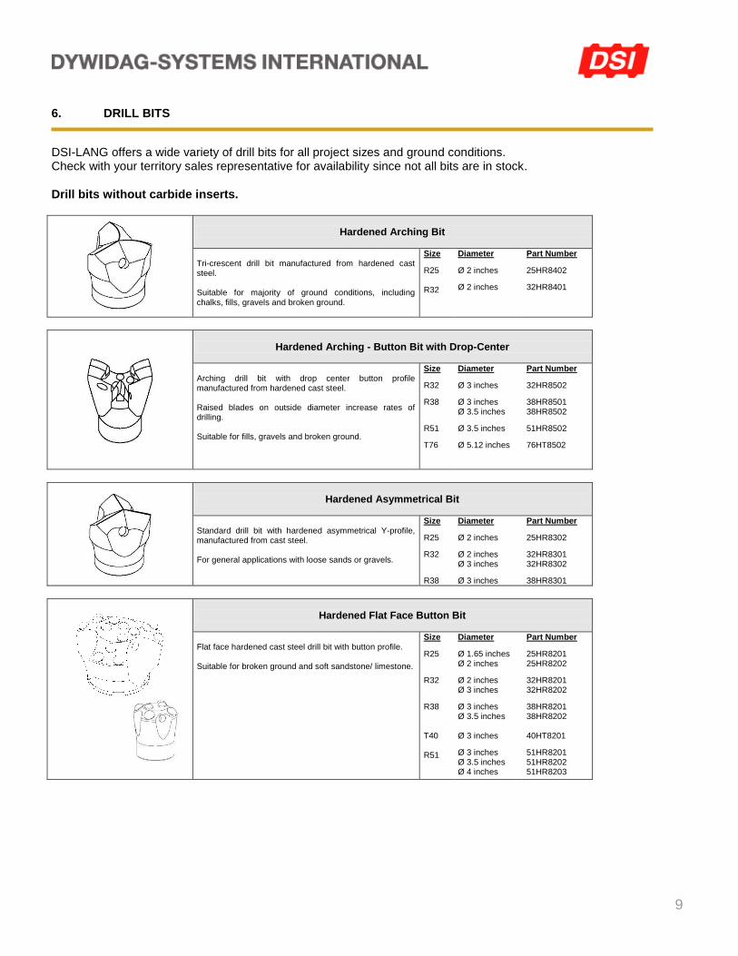
6. DRILL BITS
DSI-LANG offers a wide variety of drill bits for all project sizes and ground conditions. Check with your territory sales representative for availability since not all bits are in stock.
Drill bits without carbide inserts.
Hardened Arching Bit
Tri-crescent drill bit manufactured from hardened cast steel. Suitable for majority of ground conditions, including chalks, fills, gravels and broken ground.
Size
R25 R32
Diameter
Ø 2 inches
Ø 2 inches
Part Number
25HR8402
32HR8401
Hardened Arching - Button Bit with Drop-Center
Arching drill bit with drop center button profile manufactured from hardened cast steel. Raised blades on outside diameter increase rates of drilling. Suitable for fills, gravels and broken ground.
Size
R32
R38
R51
T76
Diameter
Ø 3 inches
Ø 3 inches Ø 3.5 inches
Ø 3.5 inches
Ø 5.12 inches
Part Number
32HR8502
38HR8501 38HR8502
51HR8502
76HT8502
Hardened Asymmetrical Bit
Standard drill bit with hardened asymmetrical Y-profile, manufactured from cast steel. For general applications with loose sands or gravels.
Size
R25
R32
R38
Diameter
Ø 2 inches
Ø 2 inches Ø 3 inches
Ø 3 inches
Part Number
25HR8302
32HR8301 32HR8302
38HR8301
Hardened Flat Face Button Bit
Flat face hardened cast steel drill bit with button profile. Suitable for broken ground and soft sandstone/ limestone.
Size
R25
R32
R38 T40 R51
Diameter
Ø 1.65 inches Ø 2 inches
Ø 2 inches Ø 3 inches
Ø 3 inches Ø 3.5 inches Ø 3 inches
Ø 3 inches Ø 3.5 inches Ø 4 inches
Part Number
25HR8201 25HR8202
32HR8201 32HR8202
38HR8201 38HR8202 40HT8201
51HR8201 51HR8202 51HR8203
10
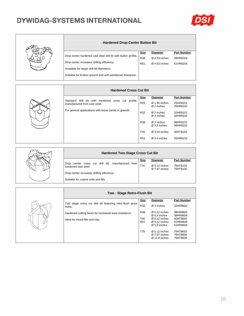
Hardened Drop-Center Button Bit
Drop center hardened cast steel drill bit with button profile. Drop center increases drilling efficiency. Available for larger drill bit diameters. Suitable for broken ground and soft sandstone/ limestone.
Size
R38
R51
Diameter
Ø 4.53 inches
Ø 4.53 inches
Part Number
38HR8204
51HR8204
Hardened Cross Cut Bit
Standard drill bit with hardened cross cut profile, manufactured from cast steel. For general applications with loose sands or gravels.
Size
R25 R32 R38 T40 R51
Diameter
Ø 1.65 inches Ø 2 inches Ø 2 inches Ø 3 inches Ø 3 inches Ø 3.5 inches Ø 3.54 inches Ø 3.5 inches
Part Number
25HR8101 25HR8102 32HR8101 32HR8102 38HR8101 38HR8102 40HT8102 32HR8102
Hardened Two-Stage Cross Cut Bit
Drop center cross cut drill bit, manufactured from hardened cast steel. Drop center increases drilling efficiency. Suitable for coarse soils and fills.
Size
T76
Diameter
Ø 5.12 inches Ø 7.87 inches
Part Number
76HT8102 76HT8105
Two - Stage Retro-Flush Bit
Two stage cross cut drill bit featuring retro-flush grout holes. Hardened cutting faces for increased wear resistance. Ideal for mixed fills and clay.
Size
R32 R38 T40 R51 T76
Diameter
Ø 3 inches Ø 5.12 inches Ø 5.9 inches Ø 5.12 inches Ø 5.12 inches Ø 5.9 inches Ø 5.12 inches Ø 7.87 inches Ø 11.8 inches
Part Number
32HR8602 38HR8605 38HR8606 40HT8605 51HR8605 51HR8606 76HT8602 76HT8605 76HT8609
11
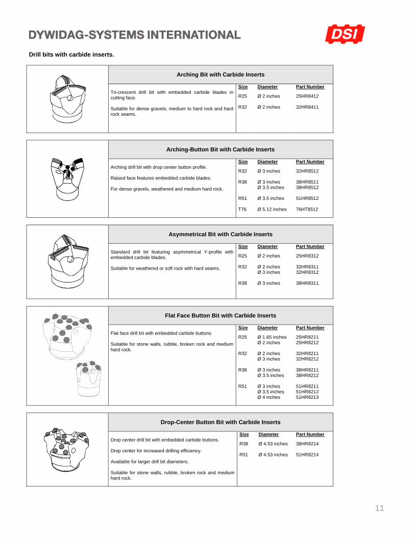
Drill bits with carbide inserts.
Arching Bit with Carbide Inserts
Tri-crescent drill bit with embedded carbide blades in cutting face. Suitable for dense gravels, medium to hard rock and hard rock seams.
Size
R25 R32
Diameter
Ø 2 inches Ø 2 inches
Part Number
25HR8412 32HR8411
Arching-Button Bit with Carbide Inserts
Arching drill bit with drop center button profile. Raised face features embedded carbide blades. For dense gravels, weathered and medium hard rock.
Size
R32 R38 R51 T76
Diameter
Ø 3 inches Ø 3 inches Ø 3.5 inches Ø 3.5 inches Ø 5.12 inches
Part Number
32HR8512 38HR8511 38HR8512 51HR8512 76HT8512
Asymmetrical Bit with Carbide Inserts
Standard drill bit featuring asymmetrical Y-profile with embedded carbide blades. Suitable for weathered or soft rock with hard seams.
Size
R25 R32 R38
Diameter
Ø 2 inches Ø 2 inches Ø 3 inches Ø 3 inches
Part Number
25HR8312 32HR8311 32HR8312 38HR8311
Flat Face Button Bit with Carbide Inserts
Flat face drill bit with embedded carbide buttons. Suitable for stone walls, rubble, broken rock and medium hard rock.
Size
R25 R32 R38 R51
Diameter
Ø 1.65 inches Ø 2 inches Ø 2 inches Ø 3 inches Ø 3 inches Ø 3.5 inches Ø 3 inches Ø 3.5 inches Ø 4 inches
Part Number
25HR8211 25HR8212 32HR8211 32HR8212 38HR8211 38HR8212 51HR8211 51HR8212 51HR8213
Drop-Center Button Bit with Carbide Inserts
Drop center drill bit with embedded carbide buttons. Drop center for increased drilling efficiency. Available for larger drill bit diameters. Suitable for stone walls, rubble, broken rock and medium hard rock.
Size
R38 R51
Diameter
Ø 4.53 inches Ø 4.53 inches
Part Number
38HR8214 51HR8214
12
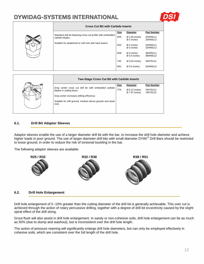
Cross Cut Bit with Carbide Inserts
Standard drill bit featuring cross cut profile with embedded carbide blades. Suitable for weathered or soft rock with hard seams.
Size
R25 R32 R38 T40 R51
Diameter
Ø 1.65 inches Ø 2 inches Ø 2 inches Ø 3 inches Ø 3 inches Ø 3.5 inches Ø 3.54 inches Ø 3.5 inches
Part Number
25HR8111 25HR8112 32HR8111 32HR8112 38HR8111 38HR8112 40HT8112 32HR8112
Two-Stage Cross Cut Bit with Carbide Inserts
Drop center cross cut drill bit with embedded carbide blades in cutting faces. Drop center increases drilling efficiency. Suitable for stiff ground, medium dense gravels and weak rock.
Size
T76
Diameter
Ø 5.12 inches Ø 7.87 inches
Part Number
76HT8112 76HT8115
6.1. Drill Bit Adaptor Sleeves Adaptor sleeves enable the use of a larger diameter drill bit with the bar, to increase the drill hole diameter and achieve higher loads in poor ground. The use of larger diameter drill bits with small diameter DYWI
® Drill Bars should be restricted
to loose ground, in order to reduce the risk of torsional buckling in the bar.
The following adaptor sleeves are available:
R25 / R32 R32 / R38 R38 / R51
6.2. Drill Hole Enlargement Drill hole enlargement of 5 -10% greater than the cutting diameter of the drill bit is generally achievable. This over cut is achieved through the action of rotary percussive drilling, together with a degree of drill bit eccentricity caused by the slight spiral effect of the drill string.
Grout flush will also assist in drill hole enlargement. In sandy or non-cohesive soils, drill hole enlargement can be as much as 50% (due to slump and washout), but is inconsistent over the drill hole length.
The action of pressure reaming will significantly enlarge drill hole diameters, but can only be employed effectively in cohesive soils, which are consistent over the full length of the drill hole.
13
7. COUPLERS The DYWI
® Drill Bar coupler features a design that enables direct end-to-end bearing between each rod, reducing energy
loss and ensuring maximum percussive energy at the drill bit. The coupler design features a center stop for each bar. All couplers exceed the ultimate strength of the bar. 7.1. Seating and Sealing of Bars within Couplers To enable correct seating of each bar within the coupler all bars must be precision cut at right angles to enable end to end bearing. A quarter turn back of the coupler on the lower bar will ensure optimum seating of the upper bar within the coupler. For using more than one coupler utilizing air flush installation (e.g. restricted access or limited head room), a reduction of flushing pressure is unavoidable due to air leakage at the couplers. The application of a thread sealant will help to reduce air loss. 7.2. Hammer Couplers, Reducing Couplers Manufactured from thick-wall steel which is machined and case hardened, both couplers can be used at high wear locations, typically just below the hammer drive. A locking torque is normally applied to the hammer couplers at the permanent joint, to avoid release when additional DYWI
® Drill Bars are added.
Hammer Couplers
R25/R25
R32/R32 R38/R38
Reducing Couplers
R25/R32 R25/R38 R32/R38 R38/R51 T45/R51 H55/R51 H64/T76
Notes: 1. When a step down (reducer) drive arrangement is used i.e. R38 shank drive to install R32 DYWI
® Drill Bar,
a locking torque should be applied at the R38 end to prevent the R32 DYWI® Drill Bar climbing into the R38
chamber.
2. Step up drive arrangements are not recommended as the additional torque overloads the smaller drive.
14
8. ACCESSORIES The DYWI
® Drill System offers a range of accessories to suit different applications. The following headings detail common
components: 8.1. Hex Nuts, Splice Couplers
Cast and machined full load hex nuts and splice couplers are available for all sizes. 8.2. Washers Wedge washers are available in pairs or individually for angles up to 20°. An oversize hole within the bearing plate is required for articulating tolerance. 8.3. Bearing Plates To accommodate proper bearing of inclined anchors with vertical walls, DSI can custom make bearing plate assemblies to meet specific project requirements. They are flat plates with center holes made of grade 36 or 50 steel. 8.4. Free Stressing Length Free stressing length enable a prestress to be transmitted between the bearing face and the bond zone, through the use of a debond tube. Free lengths are often required for sheet pile tie back applications. The free length detail incorporates a DYWI
® Drill Bar within an H.D.P.E or P.V.C. tube, which is sealed onto the bar. Short
lengths of bar remain exposed at each end to enable connection to the couplers and for connection (and release with clamp grips) from the top end drive. 8.5. Drill Hole Spacers Available for specialist applications. For general use, the spacer is not required as it snags during rotation and interferes with grout circulation in the drill hole. Note: The use of spacers does not guarantee comprehensive grout cover along the length of the bar, as it is impossible to control the grout within the drill hole. A comprehensive grout barrier can only be ensured with a sheathed encapsulation.
15
9. INSTALLATION EQUIPMENT The following equipment is required for installation:
Drill Rig
Top Drive
Grout Pump
Grout Swivel Assembly; for simultaneous drilling and grouting, (see section 10.0) (or) Heavy-duty coupler; for water flush or air flush drilling, (see section 7.2)
9.1. Drill Rigs A range of drill rigs is suitable for installing DYWI
® Drill Bars. Selection of the appropriate rig depends on:
Project Scope
Access to Work Face
Ground Conditions
Depth of Drilling
The following drill rig configurations illustrate the choices available: Crawler Mounted - Hydraulic or Air Power - (Klemm, Hütte, Ingersol Rand, Casagrande, Soilmec, etc.) Excavator Mounted - The drill boom is mounted on the dipper arm, for over-reach applications. Telehandler or Crane Basket - The drill boom is mounted on a special carrier for difficult access. 9.2. Top Drive Both rotary and rotary percussive drives can be used. Rotary percussion is the preferred method of installation as this reduces the strain on the drill string, offers greater directional stability and enables higher rates of production. Either hydraulic or air hammer drives are suitable, e.g. Krupp, Hütte, Klemm. To avoid release of components at the top end (i.e. at the grout swivel assembly or reducing coupler, when additional lengths of DYWI
® Drill Bar are added, the following steps are recommended:
1. The number of top components be kept to a minimum. 2. A locking torque is applied to all permanent joints. The torque should be sufficient to prevent premature release
but not excessive that final release is impossible. 3. Grease the top end of each DYWI
® Drill Bar.
4. For release of the DYWI® Drill Bar, percussion combined with a feed pressure and clockwise rotation will
normally free the most recent joint (i.e. at the bar). If the DYWI® Drill Bar does not release, rotation should be
limited to two turns only, as further rotation will unscrew the drill bit or couplers within the drill hole.
16
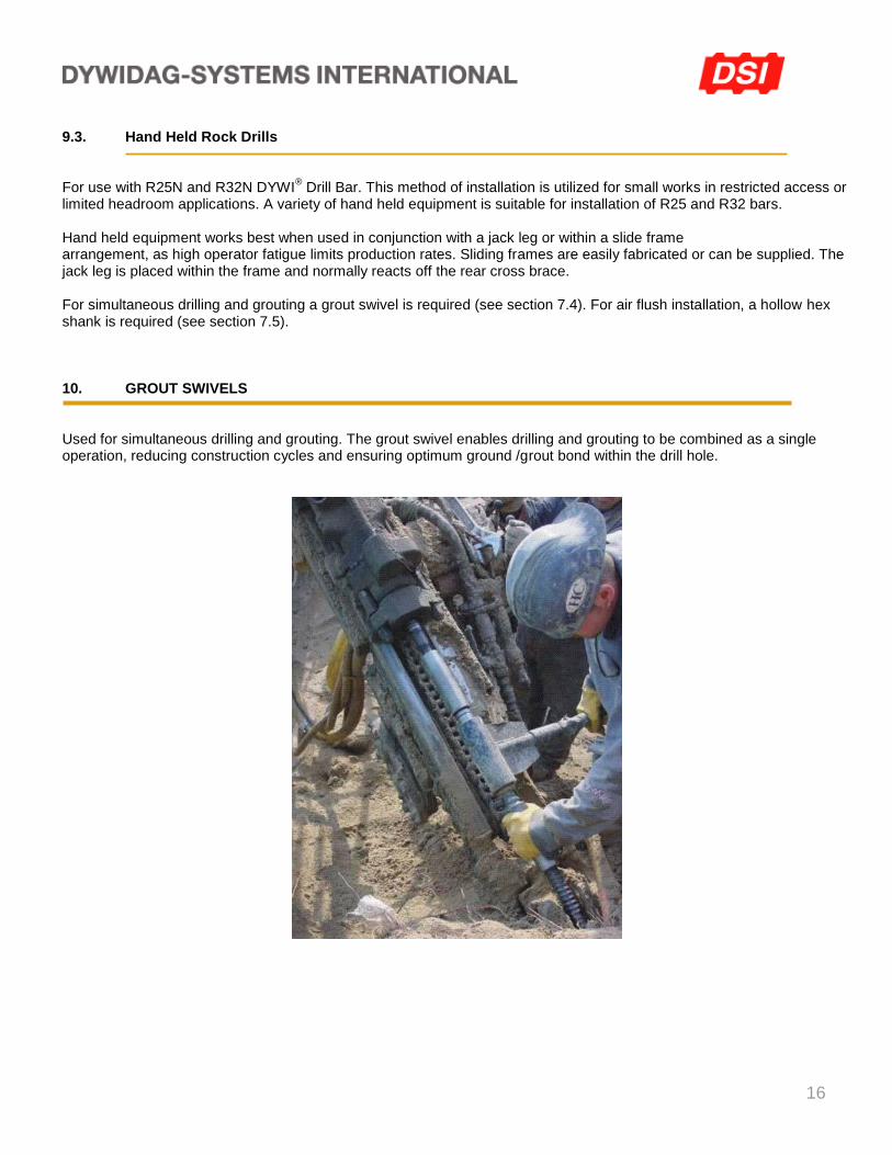
9.3. Hand Held Rock Drills For use with R25N and R32N DYWI
® Drill Bar. This method of installation is utilized for small works in restricted access or
limited headroom applications. A variety of hand held equipment is suitable for installation of R25 and R32 bars. Hand held equipment works best when used in conjunction with a jack leg or within a slide frame arrangement, as high operator fatigue limits production rates. Sliding frames are easily fabricated or can be supplied. The jack leg is placed within the frame and normally reacts off the rear cross brace. For simultaneous drilling and grouting a grout swivel is required (see section 7.4). For air flush installation, a hollow hex shank is required (see section 7.5). 10. GROUT SWIVELS Used for simultaneous drilling and grouting. The grout swivel enables drilling and grouting to be combined as a single operation, reducing construction cycles and ensuring optimum ground /grout bond within the drill hole.
17
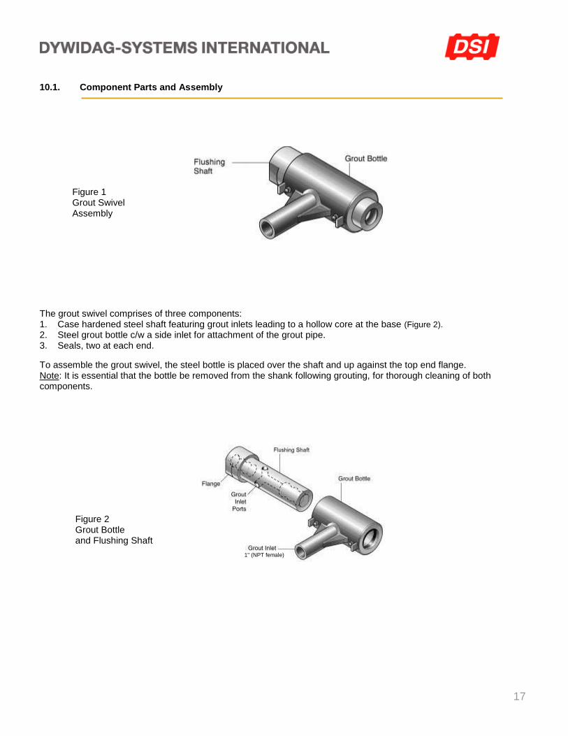
10.1. Component Parts and Assembly
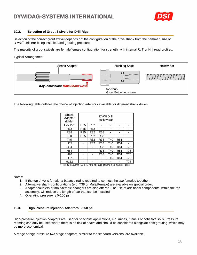
The grout swivel comprises of three components: 1. Case hardened steel shaft featuring grout inlets leading to a hollow core at the base (Figure 2). 2. Steel grout bottle c/w a side inlet for attachment of the grout pipe. 3. Seals, two at each end.
To assemble the grout swivel, the steel bottle is placed over the shaft and up against the top end flange. Note: It is essential that the bottle be removed from the shank following grouting, for thorough cleaning of both components.
Figure 1 Grout Swivel Assembly
Figure 2 Grout Bottle and Flushing Shaft
1" (NPT female)
18
10.2. Selection of Grout Swivels for Drill Rigs Selection of the correct grout swivel depends on: the configuration of the drive shank from the hammer, size of DYWI
® Drill Bar being installed and grouting pressure.
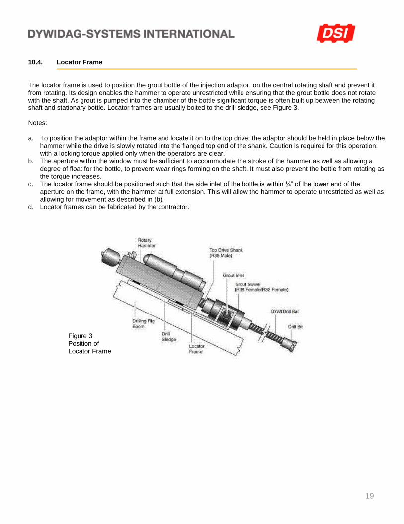
The majority of grout swivels are female/female configuration for strength, with internal R, T or H thread profiles. Typical Arrangement:
The following table outlines the choice of injection adaptors available for different shank drives:
Shank Adaptor (Male)
DYWI Drill Hollow Bar
Hex 22* R25 R32 - - - -
R32 R25 R32 - - - -
R38 R25 R32 R38 - - -
T38 R25 R32 R38 - - -
T45 - R32 R38 T40 R51 -
H55 - R32 R38 T40 R51 -
C64 - - R38 T40 R51 T76
H64 - - R38 T40 R51 T76
H90 - - R38 T40 R51 T76
H92 - - - T40 R51 T76
H112 - - - - - T76 * Hex 22 x 108mm (7/8 x 41/4") to fit chuck of hand-held hammer drills.
Notes: 1. If the top drive is female, a balance rod is required to connect the two females together. 2. Alternative shank configurations (e.g. T38 or Male/Female) are available on special order. 3. Adaptor couplers or male/female changers are also offered. The use of additional components, within the top
assembly, will reduce the length of bar that can be installed. 4. Operating pressure is 0-100 psi
10.3. High Pressure Injection Adaptors 0-250 psi High-pressure injection adaptors are used for specialist applications, e.g. mines, tunnels or cohesive soils. Pressure reaming can only be used where there is no risk of heave and should be considered alongside post grouting, which may be more economical. A range of high-pressure two stage adaptors, similar to the standard versions, are available.
for clarity Grout Bottle not shown
19
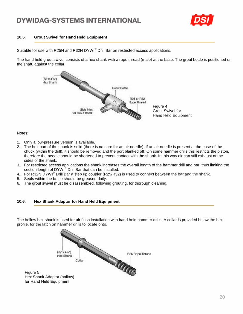
10.4. Locator Frame The locator frame is used to position the grout bottle of the injection adaptor, on the central rotating shaft and prevent it from rotating. Its design enables the hammer to operate unrestricted while ensuring that the grout bottle does not rotate with the shaft. As grout is pumped into the chamber of the bottle significant torque is often built up between the rotating shaft and stationary bottle. Locator frames are usually bolted to the drill sledge, see Figure 3. Notes: a. To position the adaptor within the frame and locate it on to the top drive; the adaptor should be held in place below the
hammer while the drive is slowly rotated into the flanged top end of the shank. Caution is required for this operation; with a locking torque applied only when the operators are clear.
b. The aperture within the window must be sufficient to accommodate the stroke of the hammer as well as allowing a degree of float for the bottle, to prevent wear rings forming on the shaft. It must also prevent the bottle from rotating as the torque increases.
c. The locator frame should be positioned such that the side inlet of the bottle is within ¼” of the lower end of the aperture on the frame, with the hammer at full extension. This will allow the hammer to operate unrestricted as well as allowing for movement as described in (b).
d. Locator frames can be fabricated by the contractor.
Figure 3 Position of Locator Frame
20
10.5. Grout Swivel for Hand Held Equipment
Suitable for use with R25N and R32N DYWI® Drill Bar on restricted access applications.
The hand held grout swivel consists of a hex shank with a rope thread (male) at the base. The grout bottle is positioned on the shaft, against the collar.
Notes: 1. Only a low-pressure version is available. 2. The hex part of the shank is solid (there is no core for an air needle). If an air needle is present at the base of the
chuck (within the drill), it should be removed and the port blanked off. On some hammer drills this restricts the piston, therefore the needle should be shortened to prevent contact with the shank. In this way air can still exhaust at the sides of the shank.
3. For restricted access applications the shank increases the overall length of the hammer drill and bar, thus limiting the section length of DYWI
® Drill Bar that can be installed.
4. For R32N DYWI® Drill Bar a step up coupler (R25/R32) is used to connect between the bar and the shank.
5. Seals within the bottle should be greased daily. 6. The grout swivel must be disassembled, following grouting, for thorough cleaning. 10.6. Hex Shank Adaptor for Hand Held Equipment The hollow hex shank is used for air flush installation with hand held hammer drills. A collar is provided below the hex profile, for the latch on hammer drills to locate onto.
Figure 4 Grout Swivel for Hand Held Equipment
Figure 5 Hex Shank Adaptor (hollow) for Hand Held Equipment
21
11. INSTALLATION
The choice of drilling technique together with grouting method is dependent upon a number of variables namely: scope of work, site access, ground conditions and depth of drill holes. The following drilling methods are used for DYWI
® Drill Bar installation:
Rotary Percussive Drilling- For all ground conditions, typically firm to hard ground. This method enables high rates of installation, provides good directional stability and helps to consolidate the grout as the percussive action of the drill acts as a vibrator.
Rotary Drilling - For soft to firm ground and some chalks. Rotary drilling ensures that the drill bit cuts the material in the drill hole. Not suitable for rubble or boulders.
Percussive Drilling - For Micro Piles in soft to medium firm ground. This method uses displacement combined with simultaneous grouting to form the drill hole. Suitable for soils where flushing or cutting with a drill bit is difficult, e.g. soft chalk or clay. Not suitable for ground conditions where the drill hole closes down behind the piling head.
11.1. Simultaneous Drilling and Grouting
Suitable for all ground conditions from gravel to clay. This technique combines drilling and grouting as a single operation ensuring that grout is placed to the full depth of the drill hole. For ground conditions where drill hole collapse is anticipated or where subsequent grout pumping from the base of the drill hole is problematical, simultaneous drilling and grouting is the preferred option. The percussive force of the hammer should be balanced with rotation of the drill bit, as advancing the drill string with excessive percussion and feed pressure, but limited rotation, will restrict the formation of a true drill hole resulting in inconsistent grout cover. The flushing and grouting efficiency of the drill bit will also be reduced. Rotation Speed: soil nailing 120 - 150 RPM, micro piling 100 - 130 RPM. Grouting pressure should be sufficient to maintain circulation at all times, with a small amount of grout return visible at the mouth of the drill hole. A constant rotation should be maintained; therefore drill motors able to deliver sufficient torque are necessary. Equipment required: Grout Swivel (see section 10). 11.2. Water Flush Drilling Followed By Grouting
Water flush is used for soft rock conditions or areas where high drill bit wear is anticipated, as it offers greater efficiency than grout in removing drill cuttings from the face of the drill bit, as well as helping to keep the temperature and ultimately the wear of the bit to an acceptable level. On completion of drilling, grout can be injected through the hollow core of the DYWI
® Drill Bar into the drill hole.
In environmentally sensitive locations, requiring the control of grout flush at the surface, water flush is often used for the first 7-10 feet. Once a sufficient depth is reached, the water flush can be switched to a grout flush and simultaneous drilling and grouting employed as in section 8.1. Equipment required: Hammer Coupler (see section 7.2) and grout line connector. Note: For rigs without a central water flush facility, a water swivel is required.
22
11.3. Air Flush Drilling Followed By Grouting
Air flush drilling is used for soft ground where flushing with water or grout is problematical e.g. soft chalk or clay, or for mining and tunneling applications. On completion of drilling the DYWI
® Drill Bar acts as a conduit for grouting.
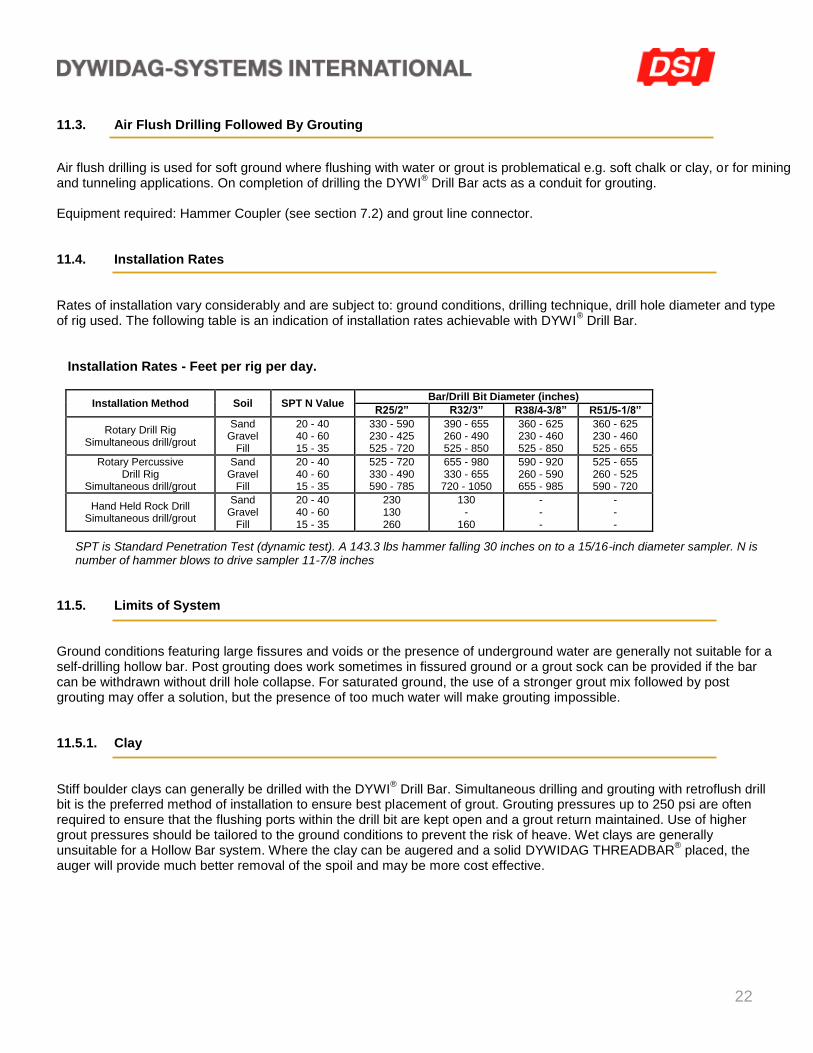
Equipment required: Hammer Coupler (see section 7.2) and grout line connector. 11.4. Installation Rates Rates of installation vary considerably and are subject to: ground conditions, drilling technique, drill hole diameter and type of rig used. The following table is an indication of installation rates achievable with DYWI
® Drill Bar.
Installation Rates - Feet per rig per day.
Installation Method Soil SPT N Value Bar/Drill Bit Diameter (inches)
R25/2” R32/3” R38/4-3/8” R51/5-1/8”
Rotary Drill Rig Simultaneous drill/grout
Sand Gravel
Fill
20 - 40 40 - 60 15 - 35
330 - 590 230 - 425 525 - 720
390 - 655 260 - 490 525 - 850
360 - 625 230 - 460 525 - 850
360 - 625 230 - 460 525 - 655
Rotary Percussive Drill Rig
Simultaneous drill/grout
Sand Gravel
Fill
20 - 40 40 - 60 15 - 35
525 - 720 330 - 490 590 - 785
655 - 980 330 - 655 720 - 1050
590 - 920 260 - 590 655 - 985
525 - 655 260 - 525 590 - 720
Hand Held Rock Drill Simultaneous drill/grout
Sand Gravel
Fill
20 - 40 40 - 60 15 - 35
230 130 260
130 -
160
- - -
- - -
SPT is Standard Penetration Test (dynamic test). A 143.3 lbs hammer falling 30 inches on to a 15/16-inch diameter sampler. N is number of hammer blows to drive sampler 11-7/8 inches
11.5. Limits of System Ground conditions featuring large fissures and voids or the presence of underground water are generally not suitable for a self-drilling hollow bar. Post grouting does work sometimes in fissured ground or a grout sock can be provided if the bar can be withdrawn without drill hole collapse. For saturated ground, the use of a stronger grout mix followed by post grouting may offer a solution, but the presence of too much water will make grouting impossible. 11.5.1. Clay Stiff boulder clays can generally be drilled with the DYWI
® Drill Bar. Simultaneous drilling and grouting with retroflush drill
bit is the preferred method of installation to ensure best placement of grout. Grouting pressures up to 250 psi are often required to ensure that the flushing ports within the drill bit are kept open and a grout return maintained. Use of higher grout pressures should be tailored to the ground conditions to prevent the risk of heave. Wet clays are generally unsuitable for a Hollow Bar system. Where the clay can be augered and a solid DYWIDAG THREADBAR
® placed, the
auger will provide much better removal of the spoil and may be more cost effective.
23
11.5.2. Rock For hard rock or where the rock is competent enough to enable open hole drilling the DYWI
® Drill Bar is not as efficient as
conventional rock drilling equipment e.g. DTH (Down the Hole Hammers). In tunneling or rock bolting applications the DYWI
® Drill Bar used in conjunction with the (Tungsten Carbide Button) drill
bit, provides the best combination for hard areas.
11.5.3. Concrete DYWI
® Drill Bar will drill through concrete, but where the slab is over 2 inch thick a conventional rock drill is more efficient.
Once a through hole is formed, a DYWI® Drill Bar and drill bit can then be used to drill through the underlying fill and into
to firmer ground.
12. GROUTING Grout is an essential part of the DYWI
® Drill System as it provides the bond between the bar and the wall of the drill hole.
Placement of the grout can either be combined with the drilling (see section 11.1 Simultaneous Drilling and Grouting) or subsequent to the drilling (see sections 11.2 Water Flush Drilling, 11.3 Air Flush Drilling). As with all grouting operations thorough mixing of the grout is essential together with rigorous wash down of all equipment following installation.
12.1. Typical Grout Mixes The Engineer determines drill hole grout type, but in most cases, regular neat cement grout is perfectly adequate unless a specific requirement is necessary, e.g., high early strengths. Curing times vary with the environment. A compressive strength of 3,000 psi is generally achieved within 3 to 7 days depending upon the ambient temperature. To determine curing times relative to the site; grout cubes should be taken, for compression testing. Grout strengths are invariably reduced as the drilled spoil is mixed with the grout but should not be lower than 3,500 psi. The most common grout mix comprises a water cement (w/c) ratio of 0.45. This is as close as practical to a 0.38 w/c ratio (the optimum ratio for full hydration). A 0.45 w/c ratio is ideal for most drilling and grouting operations where a continuous circulation of grout is possible. 12.2. Grout Pumps A variety of grout pumps are suitable for injecting grout into the DYWI
® Drill Bar. Mono Pumps
incorporating a high shear colloidal mixer offer the best performance. Selection of the appropriate pump is dependent upon the application and its ability to perform the following functions: 1. Thorough mixing of the grout - to avoid blockages at the drill bit. 2. Deliver a continuous volume - to ensure consistent grouting within the drill hole. 3. Maintain the required pressure.
24
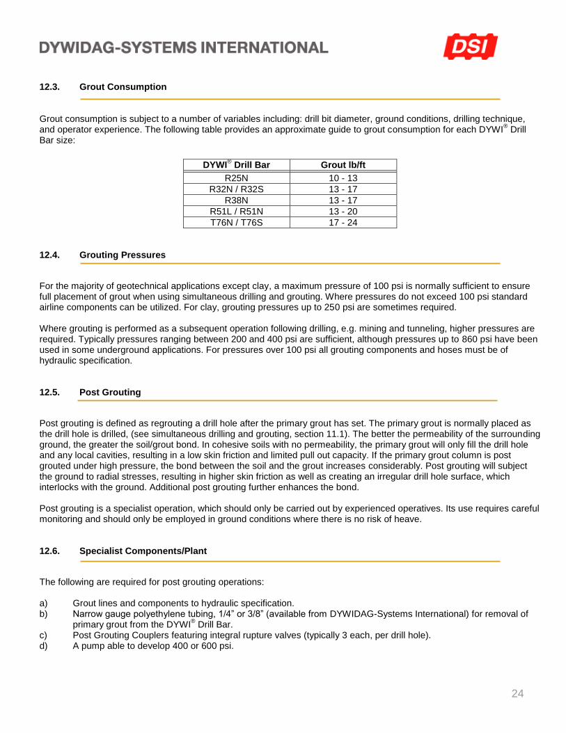
12.3. Grout Consumption Grout consumption is subject to a number of variables including: drill bit diameter, ground conditions, drilling technique, and operator experience. The following table provides an approximate guide to grout consumption for each DYWI
® Drill
Bar size:
DYWI® Drill Bar Grout lb/ft
R25N 10 - 13
R32N / R32S 13 - 17
R38N 13 - 17 R51L / R51N 13 - 20 T76N / T76S 17 - 24
12.4. Grouting Pressures
For the majority of geotechnical applications except clay, a maximum pressure of 100 psi is normally sufficient to ensure full placement of grout when using simultaneous drilling and grouting. Where pressures do not exceed 100 psi standard airline components can be utilized. For clay, grouting pressures up to 250 psi are sometimes required. Where grouting is performed as a subsequent operation following drilling, e.g. mining and tunneling, higher pressures are required. Typically pressures ranging between 200 and 400 psi are sufficient, although pressures up to 860 psi have been used in some underground applications. For pressures over 100 psi all grouting components and hoses must be of hydraulic specification. 12.5. Post Grouting
Post grouting is defined as regrouting a drill hole after the primary grout has set. The primary grout is normally placed as the drill hole is drilled, (see simultaneous drilling and grouting, section 11.1). The better the permeability of the surrounding ground, the greater the soil/grout bond. In cohesive soils with no permeability, the primary grout will only fill the drill hole and any local cavities, resulting in a low skin friction and limited pull out capacity. If the primary grout column is post grouted under high pressure, the bond between the soil and the grout increases considerably. Post grouting will subject the ground to radial stresses, resulting in higher skin friction as well as creating an irregular drill hole surface, which interlocks with the ground. Additional post grouting further enhances the bond. Post grouting is a specialist operation, which should only be carried out by experienced operatives. Its use requires careful monitoring and should only be employed in ground conditions where there is no risk of heave. 12.6. Specialist Components/Plant
The following are required for post grouting operations: a) Grout lines and components to hydraulic specification. b) Narrow gauge polyethylene tubing, 1/4” or 3/8” (available from DYWIDAG-Systems International) for removal of
primary grout from the DYWI® Drill Bar.
c) Post Grouting Couplers featuring integral rupture valves (typically 3 each, per drill hole). d) A pump able to develop 400 or 600 psi.
25
12.7. Post Grouting Procedure
Two-stage post grouting is normally the most economical for cohesive soils. Stage 1 - Primary Grouting
Use simultaneous drilling and grouting to install the DYWI® Drill Bar, maintaining grout circulation at all times with a slight
return of grout at the mouth of the drill hole. On completion of drilling, flush out the grout within the DYWI® Drill Bar with
water, by inserting a polypropylene tube to the full depth. Stage 2 - Secondary Grouting
a) Let the primary grout cure for: -2 to 12 hours; grout pumps up to 400 psi -up to 24 hours; grout pumps up to 600 psi)
b) Connect up the high-pressure pump to the DYWI® Drill Bar.
c) Fracture the primary grout column with high-pressure water injection. Do not use excessive water, only enough to achieve fracture.
d) Inject grout into the DYWI® Drill Bar up to a pressure of 200 psi. 165 to 220 lbs. of grout is
normally required to complete this operation. If a pressure of 200 psi cannot be achieved the following causes should be examined:
1. The presence of fissures within the ground. 2. Grout passages between drill holes. 3. Grout is venting in the top section of the primary grout or at other locations.
13. CORROSION PROTECTION Requirements for corrosion protection are defined by: lifespan and aggressivity of the environment (See PTI Rock and Soil Anchor recommendations). Life spans are classified as:
a) Temporary Installations (up to two years) Except for highly aggressive environments, self-drilling hollow bar systems are considered suitable for a range of temporary applications, including temporary anchors. b) Permanent Installations (life spans greater than two years) For permanent installations, corrosion protection requirements are based on:
i) aggressivity of the environment (see PTI recommendations) ii) level of risk iii) application
Corrosion protection systems, applicable to self-drilling hollow bars, are limited by the nature of installation. Sheathed sections for the free length only are ineffective as the integrity of the smooth sheath cannot be assured following abrasion damage during rotary installation, drill hole grout is not recognized as a permanent protective barrier and protective coatings are subject to abrasion damage during installation. For suitable permanent applications see 13.2.
26
13.1. Permanent Ground Anchors Permanent DYWI
® Drill bar can be used as ground anchors only on very low aggresivity soil conditions. For permanent
protection in accordance with PTI, see DYWIDAG Double Corrosion Protected Threadbars or Multistrand Anchors. 13.2. Permanent Soil Nails or Rock Bolts Hollow bar systems are generally considered acceptable for low risk applications. (i.e. soil nails or rock bolts) Supplementary protection can be added in the form of: a) galvanized or epoxy coatings (see 13.7) b) a sacrificial corrosion allowance (see 13.8) Note: Rock bolts are typically classified as having lengths up to 20 feet and lightly loaded. Applications incorporating longer lengths or higher capacities should be classified as Ground Anchors. 13.3. Permanent Micro Piles Compression: suitable for certain applications Pretensioned: hollow bar systems are not suitable 13.4. Limitations of Drill Hole Grout as a Corrosion Protection Barrier US and European geotechnical codes do not recognize drill hole grout as a corrosion protection barrier for permanent anchors. • BS8081 - Principles of Protection (Section 8.2.3. paragraph 3) “Grout injected in-situ to bond the tendon to the ground does not constitute a part of a protection system because the grout quality and integrity cannot be assured”. • EN1537 - Permanent Ground Anchor (Section 6.9.3) Drill hole grout is not recognized within the principles of protection for permanent anchors. In reality, drill hole grout can become contaminated by: drill cuttings, localized drill hole collapse or groundwater. It is also difficult to control the bleed from the grout.
DYWIDAG-Systems International reserves the right to change the design or details of its products without notice. Specific information for job details and drawings should be obtained from your DYWIDAG-Systems International Sales Engineer.
27
13.5. Grout Encapsulation, Grout Cover
Grout injected into the drill hole during installation, does not constitute an encapsulated grout i.e. within a sheath, and is unable to offer the same level of protection.
Grout cover as provided by the drill hole grout, while covering a significant proportion of the bar, cannot be guaranteed to provide a comprehensive barrier to all parts of the bar. While simultaneous drilling and grouting is the most effective way for placement of grout within the drill hole and the action of over flushing will increase the amount of grout within the drill hole, neither method is sufficient to ensure comprehensive grout cover to the bar. In essence there is a lack of control over placement of the grout within the drill hole.
The areas of highest risk are:
1. At the mouth of the drill hole (the most aggressive area in respect of corrosion). Grout cover is problematical in this zone for horizontally installed bars, as the grout will slump to the under side of the bar.
2. At the coupler location. The larger external diameter of the coupler results in reduced grout cover and the possibility that large cracks will develop.
The only system that ensures full encapsulation of the bar, within an uncontaminated grout, is a sheathed encapsulation (see DYWIDAG Double Corrosion Protected THREADBAR® Anchors). 13.6. Crack Width Control of Grout
While crack widths in the grout of less than 0.1mm may be achievable on certain sections of the bar, crack widths in the unconfined area at the mouth of the drill hole or at coupler locations cannot be controlled. As drill hole grout is not a permanent corrosion protection barrier, crack widths of the drill hole grout are irrelevant. 13.7. Galvanizing or Epoxy Coating of DYWI
® Drill Bar
DYWI
® Drill Bar assemblies can be supplied galvanized to ASTM A153, or epoxy coated to ASTM A934.
The effectiveness of any coating applied to hollow bars is questionable, as the rotary nature of installation subjects it to abrasion damage in coarse soils. In addition to abrasion, the use of pipe wrenches or hydraulic clamps for the release of the bar from the drive head can cut through any coating. Appropriate care should therefore be taken to ensure that the coating is not damaged. For added corrosion protection the coupler should be encapsulated with heat shrink sleeve. Thread design inside the couplers should be analyzed and heat shrink sleeve protection should be used. 13.8. Sacrificial Corrosion Assessment
Sacrificial corrosion assessment provides a basis for evaluating the lifespan of hollow bars in low risk applications. The method involves classification of soils into different categories of aggressivity based on a ranking procedure that incorporates tests for moisture content, pH value, presence of sulfates and chlorides and resistivity. Once the aggressivity of the soil is known, a corrosion allowance can be made for the design life of the bar.
28
14. STRESSING AND TESTING a) Simultaneous drilling and grouting of hollow bars produces a bar that is fully grouted and therefore fully bonded
over its entire length. It is not possible to isolate the drill hole grout of the bond zone (stable zone) from the drill hole grout of the unbond zone. (Sleeved free length or flushed free length is required to conduct a proof test.)
14.1. Preparation of Testing Surfaces
Testing of DYWI
® Drill Bar falls into two categories:
a) Soil Nails b) Temporary Ground Anchors, Micro Piles and Rock Bolts.
- Soil Nails are usually tested against a soft face on slopes. Due consideration should therefore be given to both the angle and the area of the bearing surface to stress against.
- Ground Anchors, Micro Piles and Rock Bolts are usually installed in applications where a hard face is readily available for the jack to react against, e.g. sheet piles (for tie back anchors).
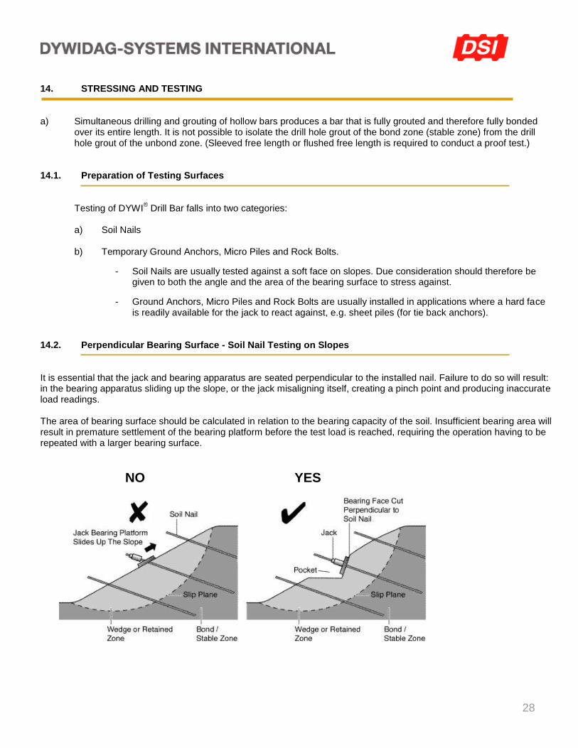
14.2. Perpendicular Bearing Surface - Soil Nail Testing on Slopes It is essential that the jack and bearing apparatus are seated perpendicular to the installed nail. Failure to do so will result: in the bearing apparatus sliding up the slope, or the jack misaligning itself, creating a pinch point and producing inaccurate load readings. The area of bearing surface should be calculated in relation to the bearing capacity of the soil. Insufficient bearing area will result in premature settlement of the bearing platform before the test load is reached, requiring the operation having to be repeated with a larger bearing surface.
NO YES
29
14.3. Pocket Dimensions To ensure that the bearing surface is perpendicular to the angle of installation, a pocket is normally cut into the slope. Pocket dimensions vary. It is important that there is as much bearing surface above the nail as there is below. The cutting of a pocket reduces the installed depth of the nail; therefore an additional allowance for depth of installation should be made, to ensure that a sufficient length of nail remains embedded for the test (i.e. over install the nail). 14.4. Alignment Loads An alignment load of 10% of design load (min. 5 kips) is necessary to ensure:
a) That the jack and bearing platform are sufficiently seated to compress any spaces between the bearing surfaces.
b) The line of extension for the nail is kept constant: to ensure contact between the dial gauge and the top of the bar. A circular plate (4 inch) on the end of the bar will greatly assist this operation.
14.5. Stressing and Testing Equipment Precast Concrete Panel or Steel Plates: Minimum 4’ x 4’
Spreader Beam: Two channels of adequate height back to back with 2.50” clearance in the middle.
Calibrated Ram Jack / Gauge Stressing Chair: Minimum of 6” stroke to accommodate bearing platform settlement.
Dial Indicator Gauge & Tripod: To provide an independent datum for recording nail extension. Note: The dial gauge must be mounted on a fixed independent tripod.
14.6. Exposed Bar Requirement for Jack Connection The placement of the hollow ram jack over the bar can be achieved in two ways:
a) Three feet of exposed bar (above the bearing platform) – the jack is slid over the bar (if a pocket is cut into the slope sufficient bar is normally exposed).
b) Short lengths of exposed bar – a 3’ long bar and coupler are used to connect to the exposed bar
(minimum 5”) and run through to the back nut at the top of the jack.
30
14.7. Testing The following sections outline the range of tests that can be applied to DYWI
® Drill Bars, together with common load
factors and general procedures. 14.8. Proof Test The proof test is used to establish the pull out performance of DYWI
® Drill Bars. Test loads are significantly higher than
would be applied to the main works, as the objective is to demonstrate the bond performance in the ground. In general terms the test load should not exceed 75% of the ultimate strength of the bar, except in special circumstances where a maximum load of 80% (of the ultimate strength) may be used with the engineer’s consent. Recommended maximum test ratio is 1.5 x working load. For locking-off of soil nails, a torque wrench is normally employed as the quantities are often large and at relatively low loads. For ground anchors, a hollow ram jack is used as the loads are higher and greater accuracy is required. 14.9. Load Increments Load increments and hold periods should be determined to ensure a controlled displacement. Where possible, load increments should be concentrated around the predicted failure point to provide sufficient data for detailed analysis of the peak load. For soil nails with low loads progressive loading is preferable to cyclic loading, as releasing the load tends to cause misalignment of the jack and inaccurate extension readings. 14.10. Load and Extension Readings Load is measured through a pressure gauge incorporated within the hydraulic circuit of the jack. The display ensures the maintenance of a constant pressure during hold periods. Extension is measured by a dial gauge in contact with a plate at the end of the bar. The dial gauge is mounted on a tripod, independent of the jack bearing apparatus. Settlement of the bearing plate will not affect extension readings on the dial gauge as it is mounted separately. Readings are only affected when misalignment occurs. Data recorded is plotted on a graph to produce a load vs. displacement curve. 14.11. Pull Out Performance The critical factor affecting achievable loads for: soil nails, ground anchors and micropiles, is the ground/grout interface; not the bar/grout interface. Selection of the correct installation method for the ground conditions is critical, as the placement of the grout directly affects the performance.
31
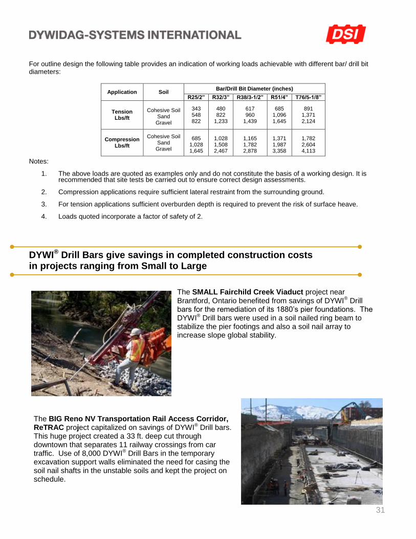
For outline design the following table provides an indication of working loads achievable with different bar/ drill bit diameters:
Application Soil Bar/Drill Bit Diameter (inches)
R25/2” R32/3” R38/3-1/2” R51/4” T76/5-1/8”
Tension Lbs/ft
Cohesive Soil
Sand Gravel
343 548 822
480 822
1,233
617 960
1,439
685 1,096 1,645
891 1,371 2,124
Compression Lbs/ft
Cohesive Soil Sand
Gravel
685 1,028 1,645
1,028 1,508 2,467
1,165 1,782 2,878
1,371 1,987 3,358
1,782 2,604 4,113
Notes:
1. The above loads are quoted as examples only and do not constitute the basis of a working design. It is recommended that site tests be carried out to ensure correct design assessments.
2. Compression applications require sufficient lateral restraint from the surrounding ground.
3. For tension applications sufficient overburden depth is required to prevent the risk of surface heave.
4. Loads quoted incorporate a factor of safety of 2.
DYWI® Drill Bars give savings in completed construction costs in projects ranging from Small to Large
The SMALL Fairchild Creek Viaduct project near Brantford, Ontario benefited from savings of DYWI® Drill bars for the remediation of its 1880’s pier foundations. The DYWI® Drill bars were used in a soil nailed ring beam to stabilize the pier footings and also a soil nail array to increase slope global stability.
The BIG Reno NV Transportation Rail Access Corridor, ReTRAC project capitalized on savings of DYWI® Drill bars. This huge project created a 33 ft. deep cut through downtown that separates 11 railway crossings from car traffic. Use of 8,000 DYWI® Drill Bars in the temporary excavation support walls eliminated the need for casing the soil nail shafts in the unstable soils and kept the project on schedule.

32
Copyright © 2012 by DYWIDAG-Systems International. All rights reserved. Revised March 2012