Embed Size (px)
Citation preview

PDH Star | T / F: (833) PDH‐STAR (734‐7827) | E: [email protected]
E‐087 HV Systems for Hydroelectric Power Plants Instructor: J Paul Guyer, P.E., R.A. Course ID: E‐087 PDH Hours: 2 PDH
J. Paul Guyer, P.E., R.A. Editor Paul Guyer is a registered civil engineer, mechanical engineer, fire protection engineer and architect with 35 years of experience designing buildings and related infrastructure. For an additional 9 years he was a principal staff advisor to the California Legislature on capital outlay and infrastructure issues. He is a graduate of Stanford University and has held numerous national, state and local offices with the American Society of Civil Engineers, Architectural Engineering Institute and National Society of Professional Engineers. He is a Fellow of ASCE, AEI and CABE (U.K.).
An Introduction to High Voltage Systems for Hydroelectric Power Plants
An Introduction to High Voltage Systems for
Hydroelectric Power Plants
J. Paul Guyer, P.E., R.A.
Editor
The Clubhouse Press El Macero, California
CONTENTS
1. POWER TRANSFORMERS
2. ELECTRICAL CHARACTERISTICS
3. HIGH VOLTAGE SYSTEM
(This publication is adapted from the Unified Facilities Criteria of the United States government which are in the public domain, have been authorized for unlimited distribution, and are not copyrighted.)
© J. Paul Guyer 2018 1
1. POWER TRANSFORMERS
1.1 GENERAL
1.1.1 TYPE. Step-up transformers for use with main units should be of the oil immersed
type for outdoor operation, with a cooling system, suited to the location.
1.1.2 THREE-PHASE TRANSFORMERS. In the majority of applications, three-phase
transformers should be used for generator step-up (GSU) applications for the following
reasons: (1) Higher efficiency than three single-phase units of equivalent capacity. (2)
Smaller space requirements. (3) Lower installed cost. (4) Lower probability of failure
when properly protected by surge arresters, thermal devices, and oil preservation
systems. (5) Lower total weight. (6) Reduction in weights and dimensions making larger
capacities available within practical weight and size limitations.
1.1.3 EHV APPLICATIONS. In applications involving interconnection to EHV (345 kV
and above) systems, reliability and application considerations dictate the use of single-
phase units due to lack of satisfactory industry experience with three-phase EHV GSU
transformers.
1.1.4 TRANSFORMER FEATURES. Regardless of winding configuration, for any given
voltage and kVA rating, with normal temperature rise, the following features should be
analyzed for their effect on transformer life cycle costs: (1) Type of cooling. (2)
Insulation level of high-voltage winding. (3) Departure from normal design impedance.
1.1.5 TRANSFORMER CONSTRUCTION. There are two types of construction used for
GSU transformers. These are the core form type and the shell form type. Core form
transformers generally are supplied by manufacturers for lower voltage and lower MVA
ratings. The core form unit is adaptable to a wide range of design parameters, is
economical to manufacture, but generally has a low kVA-toweight ratio. Typical HV
© J. Paul Guyer 2018 2
ranges are 230 kV and less and 75 MVA and less. Shell form transformers have a high
kVA-to-weight ratio and find favor on EHV and high MVA applications. They have better
short-circuit strength characteristics, are less immune to transit damage, but have a
more labor-intensive manufacturing process. Both forms of construction are permitted
by Corps’ transformer guide specifications.
1.2 RATING The full load kVA rating of the step-up transformer should be at least equal
to the maximum kVA rating of the generator or generators with which they are
associated. Where transformers with auxiliary cooling facilities have dual or triple kVA
ratings, the maximum transformer rating should match the maximum generator rating.
1.3 COOLING
1.3.1 GENERAL. The standard classes of transformer cooling systems are listed in
Paragraph 5.1, IEEE C57.12.00. Transformers, when located at the powerhouse,
should be sited so unrestricted ambient air circulation is allowed. The transformer rating
is based on full use of the transformer cooling equipment.
1.3.2 FORCED COOLING. The use of forced-air cooling will increase the continuous
self-cooled rating of the transformer 15 percent for transformers rated 2499 kVA and
below, 25 percent for single-phase transformers rated 2500 to 9999 kVA and three-
phase transformers rated 2500 to 11999 kVA, and 33-1/3 percent for single-phase
transformers rated 10000 kVA and above and three-phase transformers rated 12000
kVA and above. High-velocity fans on the largest size groups will increase the self-
cooled rating 66-2/3 percent. Forced-oil cooled transformers, whenever energized, must
be operated with the circulating oil pumps operating. Forced-oil transformers with air
coolers do not have a self-cooled rating without air-cooling equipment in operation
unless they are special units with a “triple rating.”
1.4 TEMPERATURE CONSIDERATIONS. In determining the transformer rating,
consideration should be given to the temperature conditions at the point of installation.
© J. Paul Guyer 2018 3
High ambient temperatures may necessitate increasing the transformer rating in order
to keep the winding temperature within permissible limits. If the temperatures will
exceed those specified under “Service Conditions” in IEEE C57.12.00, a larger
transformer may be required. IEEE C57.92 should be consulted in determining the
rating required for overloads and high temperature conditions. d. Unusual requirements.
Class OA/FA and Class FOA meet all the usual requirements for transformers located in
hydro plant switchyards. The use of triple rated transformers such as Class OA/FA/FA is
seldom required unless the particular installation services a load with a recurring short
time peak.
1.5 CLASS FOA TRANSFORMERS. On Class FOA transformers, there are certain
considerations regarding static electrification (build-up of charge on the transformer
windings due to oil flow). Transformer suppliers require oil pump operation whenever an
FOA transformer is energized. Static electrification is important to consider when
designing the desired operation of the cooling, and can result in the following cooling
considerations: (1) Decrease in oil flow velocity requirements (for forced-oil cooled
units). (2) Modifying of cooling equipment controls to have pumps come on in stages.
(3) Operation of pumps prior to energizing transformer.
© J. Paul Guyer 2018 4
2. ELECTRICAL CHARACTERISTICS
2.1 VOLTAGE.
2.1.1 VOLTAGE RATINGS and ratios should conform to ANSI C84.1 preferred ratings
wherever possible. The high-voltage rating should be suitable for the voltage of the
transmission system to which it will be connected, with proper consideration for
increases in transmission voltage that may be planned for the near future. In some
cases this may warrant the construction of high-voltage windings for series or parallel
operation, with bushings for the higher voltage, or windings suitable for the higher
voltage tapped for the present operating voltage.
2.1.2 CONSIDERATION should also be given to the voltage rating specified for the low-
voltage winding. For plants connected to EHV systems, the low-voltage winding rating
should match the generator voltage rating to optimally match the generator’s reactive
capability in “bucking” the transmission line voltage. For 230-kV transmission systems
and below, the transformer low voltage rating should be 5 percent below the generator
voltage rating to optimally match the generator’s reactive capability when “boosting”
transmission line voltage. IEEE C57.116 and EPRI EL-5036, Volume 2, provide further
guidance on considerations in evaluating suitable voltage ratings for the GSU
transformer.
2.2 HIGH-VOLTAGE BIL.
2.2.1 BASIC IMPULSE INSULATION LEVELS (BIL) associated with the nominal
transmission system voltage are shown in Table 1 of IEEE C57.12.14. With the advent
of metal oxide surge arresters, significant economic savings can be made in the
procurement of power transformers by specifying reduced BIL levels in conjunction with
the application of the appropriate metal oxide arrester for transformer surge protection.
To determine appropriate values, an insulation coordination study should be made.
© J. Paul Guyer 2018 5
Studies involve coordinating and determining adequate protective margins for the
following transformer insulation characteristics:
2.2.1.1 CHOPPED-WAVE WITHSTAND (CWW).
2.2.1.2 BASIC IMPULSE INSULATION LEVEL (BIL).
2.2.1.3 SWITCHING SURGE LEVEL (SSL).
2.2.2 IF THERE IS REASON TO believe the transmission system presently operating
with solidly grounded neutrals may be equipped with regulating transformers or neutral
reactors in the future, the neutral insulation level should be specified to agree with Table
7 of IEEE C57.12.00.
2.2.3 IMPEDANCE.
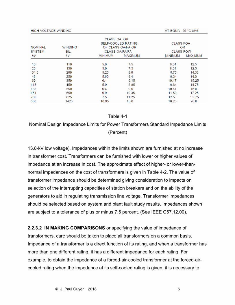
2.2.3.1 IMPEDANCE OF THE TRANSFORMERS has a material effect on system
stability, short-circuit currents, and transmission line regulation, and it is usually
desirable to keep the impedance at the lower limit of normal impedance design values.
Table 4-1 illustrates the range of values available in a normal two-winding transformer
design (values shown are for GSU transformers with
© J. Paul Guyer 2018 6
Table 4-1
Nominal Design Impedance Limits for Power Transformers Standard Impedance Limits
(Percent)
13.8-kV low voltage). Impedances within the limits shown are furnished at no increase
in transformer cost. Transformers can be furnished with lower or higher values of
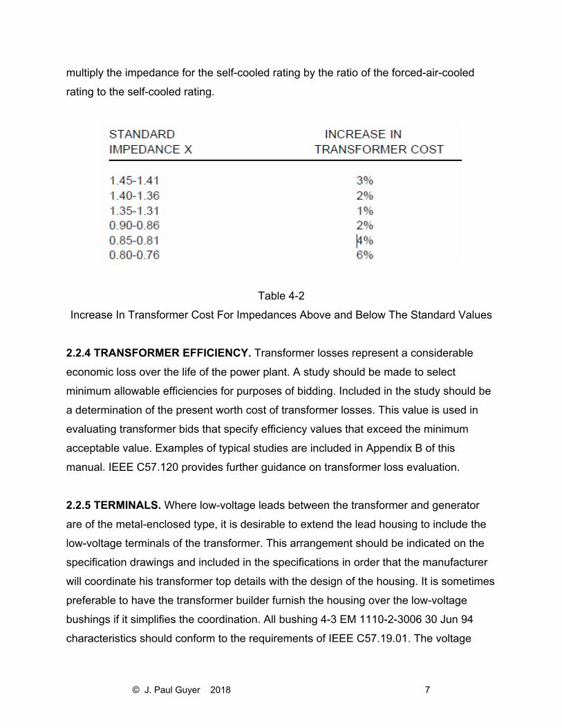
impedance at an increase in cost. The approximate effect of higher- or lower-than-
normal impedances on the cost of transformers is given in Table 4-2. The value of
transformer impedance should be determined giving consideration to impacts on
selection of the interrupting capacities of station breakers and on the ability of the
generators to aid in regulating transmission line voltage. Transformer impedances
should be selected based on system and plant fault study results. Impedances shown
are subject to a tolerance of plus or minus 7.5 percent. (See IEEE C57.12.00).
2.2.3.2 IN MAKING COMPARISONS or specifying the value of impedance of
transformers, care should be taken to place all transformers on a common basis.
Impedance of a transformer is a direct function of its rating, and when a transformer has
more than one different rating, it has a different impedance for each rating. For
example, to obtain the impedance of a forced-air-cooled transformer at the forced-air-
cooled rating when the impedance at its self-cooled rating is given, it is necessary to
© J. Paul Guyer 2018 7
multiply the impedance for the self-cooled rating by the ratio of the forced-air-cooled
rating to the self-cooled rating.
Table 4-2
Increase In Transformer Cost For Impedances Above and Below The Standard Values
2.2.4 TRANSFORMER EFFICIENCY. Transformer losses represent a considerable
economic loss over the life of the power plant. A study should be made to select
minimum allowable efficiencies for purposes of bidding. Included in the study should be
a determination of the present worth cost of transformer losses. This value is used in
evaluating transformer bids that specify efficiency values that exceed the minimum
acceptable value. Examples of typical studies are included in Appendix B of this
manual. IEEE C57.120 provides further guidance on transformer loss evaluation.
2.2.5 TERMINALS. Where low-voltage leads between the transformer and generator
are of the metal-enclosed type, it is desirable to extend the lead housing to include the
low-voltage terminals of the transformer. This arrangement should be indicated on the
specification drawings and included in the specifications in order that the manufacturer
will coordinate his transformer top details with the design of the housing. It is sometimes
preferable to have the transformer builder furnish the housing over the low-voltage
bushings if it simplifies the coordination. All bushing 4-3 EM 1110-2-3006 30 Jun 94
characteristics should conform to the requirements of IEEE C57.19.01. The voltage
© J. Paul Guyer 2018 8
rating should correspond to the insulation level of the associated winding. Where
transformers are installed at elevations of more than 3,300 ft above sea level, bushings
of the next higher voltage classification may be required. Bushings for neutral
connections should be selected to suit the insulation level of the neutral.
2.2.6 ACCESSORIES
2.2.6.1 OIL PRESERVATION SYSTEMS. Three different oil preservation systems are
available, as described below. The first two systems are preferred for generator step-up
transformers: (1) Inert gas pressure system. Positive nitrogen gas pressure is
maintained in the space between the top of the oil and the tank cover from a cylinder or
group of cylinders through a pressure-reducing valve. (2) Air-cell, constant-pressure,
reservoir tank system. A system of one or more oil reservoirs, each containing an air
cell arranged to prevent direct contact between the oil and the air. (3) Sealed tank. Gas
is admitted to the space above the oil and the tank is sealed. Expansion tanks for the
gas are provided on some sizes. Sealed tank construction is employed for 2,500 kVA
and smaller sizes.
2.2.6.2 OIL FLOW ALARM. Transformers that depend upon pumped circulation of the
oil for cooling should be equipped with devices that can be connected to sound an
alarm, to prevent closing of the energizing power circuit, or to deenergize the
transformer with loss of oil flow. In forced-oil-cooled units, hot spot detectors should be
provided which can be connected to unload the transformer if the temperature exceeds
that at which the second oil pump is expected to cut in. FOA transformers should
employ control schemes to ensure pump operation prior to energizing the transformer.
2.2.6.3 SURGE ARRESTERS. Surge arresters are located near the transformer
terminals to provide protection of the high-voltage windings. Normal practice is to
provide brackets on the transformer case (230-kV HV and below) for mounting the
selected surge arrester.
© J. Paul Guyer 2018 9
2.2.6.4 FANS AND PUMPS. The axial-flow fans provided for supplementary cooling on
Class OA/FA transformers are equipped with special motors standardized for 115-V and
230-V single-phase or 208-V three-phase operation. Likewise, oil circulating pumps for
FOA transformers are set up for single-phase AC service. Standard Corps of Engineers
practice is to supply 480-V, three-phase power to the transformer and have the
transformer manufacturer provide necessary conversion equipment.
2.2.6.5 ON-LINE DISSOLVED GAS MONITORING SYSTEM. The detection of certain
gases, generated in an oil-filled transformer in service, is frequently the first available
indication of possible malfunction that may eventually lead to the transformer failure if
not corrected. The monitoring system can provide gas analysis of certain gases from
gas spaces of a transformer. The system output contacts can be connected for an alarm
or to unload the transformer if the gas levels exceed a set point. The type of gases
generated, during the abnormal transformer conditions, is described in IEEE C57.104.
2.2.6.6 TEMPERATURE DETECTORS. A dial-type temperature indicating device with
adjustable alarm contacts should be provided for oil temperature indication. Winding
RTDs should be provided, and monitored by the plant control system or a stand-alone
temperature recorder, if one is provided for the generator and turbine RTDs. At least
two RTDs in each winding should be provided.
2.2.6.7 LIFTING DEVICES. If powerhouse cranes are to be used for transformer
handling, the manufacturer’s design of the lifting equipment should be carefully
coordinated with the crane clearance and with the dimensions of the crane hooks. The
lifting equipment should safely clear bushings when handling the completely assembled
transformer, and should be properly designed to compensate for eccentric weight
dispositions of the complete transformer with bushings.
2.2.6.8 ON-LINE MONITORING SYSTEMS. In addition to the on-line dissolved gas
monitoring system, other on-line systems are available to monitor abnormal transformer
conditions. These include: (1) Partial discharge analysis. (2) Acoustical monitoring. (3)

© J. Paul Guyer 2018 10
Fiber-optic winding temperature monitoring. (4) Bearing wear sensor (forced-oil-cooled
units). (5) Load tap changer monitor (if load tap changers are used). Early detection of
the potential for a condition leading to a forced outage of a critical transformer bank
could more than offset the high initial costs of these transformer accessories by
avoiding a more costly loss of generation.
2.2.6.9 DIAL-TYPE INDICATING DEVICES. Dial-type indicating devices should be
provided for: (1) Liquid level indication. (2) Liquid temperature indicator. (3) Oil flow
indicators (see paragraph 4-6b). These are in addition to the dial-type indicators that are
part of the winding temperature systems.
2.2.7 OIL CONTAINMENT SYSTEMS. If any oil-filled transformers are used in the
power plant, provisions are made to contain any oil leakage or spillage resulting from a
ruptured tank or a broken drain valve. The volume of the containment should be
sufficient to retain all of the oil in the transformer to prevent spillage into waterways or
contamination of soil around the transformer foundations. Special provisions (oil-water
separators, oil traps, etc.) must be made to allow for separation of oil spillage versus
normal water runoff from storms, etc. IEEE 979 and 980 provide guidance on design
considerations for oil containment systems.
2.2.8 FIRE SUPPRESSION SYSTEMS
2.2.8.1 GENERAL. Fire suppression measures and protective equipment should be
used if the plant’s oil-filled transformers are located in close proximity to adjacent
transformers, plant equipment, or power plant structures. Oil-filled transformers contain
the largest amount of combustible material in the power plant and so require due
consideration of their location and the use of fire suppression measures. Fires in
transformers are caused primarily from breakdown of their insulation systems, although
bushing failures and surge arrester failures can also be causes. With failure of the
transformer’s insulation system, internal arcing follows, creating rapid internal tank
© J. Paul Guyer 2018 11
pressures and possible tank rupture. With a tank rupture, a large volume of burning oil
may be expelled over a large area, creating the possibility of an intense fire.
2.2.8.2 SUPPRESSION MEASURES. Suppression measures include the use of fire
quenching pits or sumps filled with coarse rock surrounding the transformer foundation
and physical separation of the transformer from adjacent equipment or structures.
Physical separation in distance is also augmented by the use of fire-rated barriers or by
firerated building wall construction when installation prevents maintaining minimum
recommended separations. Economical plant arrangements generally result in less than
recommended minimums between transformers and adjacent structures so water
deluge systems are supplied as a fire prevention and suppression technique. The
systems should be of the dry pipe type (to prevent freeze-up in cold weather) with the
system deluge valves actuated either by thermostats, by manual break-glass stations
near the transformer installation, or by the transformer differential protective relay.
© J. Paul Guyer 2018 12
3. HIGH-VOLTAGE SYSTEM
3.1 DEFINITION The high-voltage system as treated in this discussion includes all
equipment and conductors that carry current at transmission line-voltage, with their
insulators, supports, switching equipment, and protective devices. The system begins
with the high-voltage terminals of the step-up power transformers and extends to the
point where transmission lines are attached to the switchyard structure. High-voltage
systems include those systems operating at 69 kV and above, although 34.5-kV and 46-
kV systems that are subtransmission-voltage systems are also covered in this
discussion. Transmission line corridors from the powerhouse to the switchyard should
allow adequate clearance for maintenance equipment access, and clear working space.
Working clearances shall be in accordance with the applicable sections of ANSI C2,
Part 2.
3.2 SWITCHYARD
3.2.1 SPACE AROUND THE SWITCHYARD. Adequate space should be allowed to
provide for extension of the switchyard facilities when generating units or transmission
lines are added in the future. The immediate surroundings should permit the building of
lines to the switchyard area from at least one direction without the need for heavy dead-
end structures in the yard.
3.2.2 SWITCHYARD LOCATION. Subject to these criteria, the switchyard should be
sited as near to the powerhouse as space permits, in order to minimize the length of
control circuits and power feeders and also to enable use of service facilities located in
the powerhouse. c. Switchyard fencing. A chain link woven wire fence not less than 7 ft
high and topped with three strands of barbed wire slanting outward at a 45-deg angle,
or concertina wire, with lockable gates, should be provided to enclose the entire yard.
3 3 SWITCHING SCHEME. The type of high-voltage switching scheme should be
selected after a careful study of the flexibility and protection needed in the station for the
© J. Paul Guyer 2018 13
initial installation, and also when the station is developed to its probable maximum
capacity. A detailed discussion of the advantages and disadvantages of various high-
voltage switching schemes is included in this discussion.
3.3.1 MINIMUM REQUIREMENTS. The initial installation may require only the
connecting of a single transformer bank to a single transmission line. In this case, one
circuit breaker, one set of disconnects with grounding blades, and one bypass
disconnecting switch should be adequate. The high-voltage circuit breaker may even be
omitted under some conditions. The receiving utility generally establishes the system
criteria that will dictate the need for a high side breaker.
3.3.2 BUS STRUCTURE. When another powerhouse unit or transmission line is added,
some form of bus structure will be required. The original bus structure should be
designed with the possibility of becoming a part of the ultimate arrangement. Better
known arrangements are the main and transfer bus scheme, the ring bus scheme, the
breaker-and-a-half scheme, and the double bus-double breaker scheme.
3.3.3 MAIN AND TRANSFER BUS SCHEME.
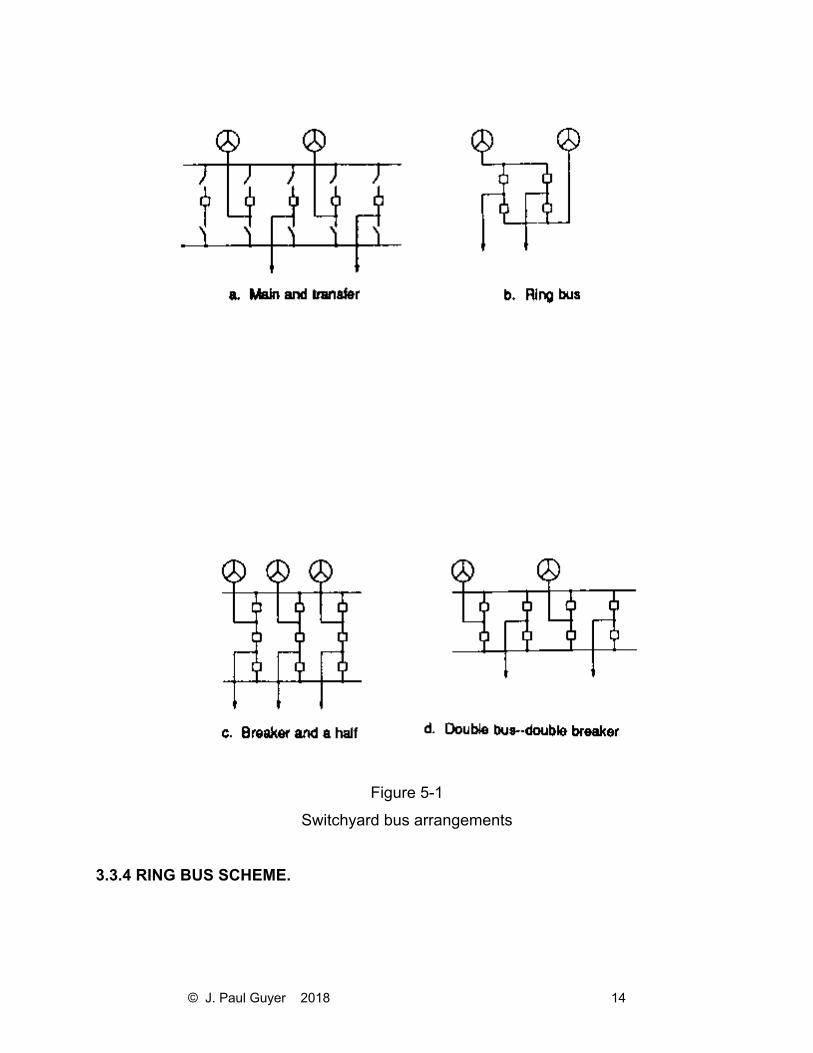
3.3.3.1 THE MAIN AND TRANSFER BUS SCHEME, Figure 5a, consists of two
independent buses, one of which is normally energized. Under normal conditions, all
circuits are tied to the main bus. The transfer bus is used to provide service through the
transfer bus tie breaker when it becomes necessary to remove a breaker from service.
3.3.3.2 ADVANTAGES of the main and transfer bus arrangement include: (a) Continuity
of service and protection during breaker maintenance. (b) Ease of expansion. (c) Small
land area requirements. (d) Low cost.
3.3.3.3 DISADVANTAGES INCLUDE: (a) Breaker failure or bus fault causes the loss of
the entire station. (b) Bus tie breaker must have protection schemes to be able to
substitute for all line breakers. (c) An additional tie breaker is required.
© J. Paul Guyer 2018 14
Figure 5-1
Switchyard bus arrangements
3.3.4 RING BUS SCHEME.
© J. Paul Guyer 2018 15
3.3.4.1THE RING BUS, Figure 5-1b, consists of a loop of bus work with each bus
section separated by a breaker. Only limited bus sections and circuits can be removed
from service in the event of a line or bus fault. A line fault results in the loss of the
breakers on each side of the line, while a breaker failure will result in the removal of two
bus sections from service. The ring bus arrangement allows for circuit breaker
maintenance without interruption of service to any circuit.
3.3.4.2 THE ADVANTAGES of the ring bus scheme include: (a) Low cost (one breaker
per line section). (b) High reliability and operational flexibility. (c) Continuity of service
during breaker and bus maintenance. (d) Double feed to each circuit. (e) Expandable to
breaker-and-a-half scheme.
3.3.4.3 DISADVANTAGES INCLUDE: (a) Each circuit must have its own potential
source. (b) Usually limited to four circuits.
3.3.5 BREAKER-AND-A-HALF SCHEME.
3.3.5.1THE BREAKER-AND-A-HALF ARRANGEMENT, Figure 5-1c, provides for two
main buses, both normally energized. Between the buses are three circuit breakers and
two circuits. This arrangement allows for breaker maintenance without interruption of
service. A fault on either bus will cause no circuit interruption. A breaker failure results in
the loss of two circuits if a common breaker fails and only one circuit if an outside
breaker fails.
3.3.5.2 THE ADVANTAGES of the breaker-and-a-half scheme include: (a) High
reliability and operational flexibility. (b) Capability of isolating any circuit breaker or
either main bus for maintenance without service interruption. (c) A bus fault does not
interrupt service. (d) Double feed to each circuit. (e) All switching can be done with
circuit breakers.
© J. Paul Guyer 2018 16
3.3.5.3 THE DISADVANTAGES INCLUDE: (a) Added cost of one half breaker for each
circuit. (b) Protection and control schemes are more complex.
3.3.6 DOUBLE BUS-DOUBLE BREAKER SCHEME.
3.3.6.1 THE DOUBLE BUS-DOUBLE BREAKER ARRANGEMENT, Figure 5-1d,
consists of two main buses, both normally energized. Between the main buses are two
breakers and one circuit. This arrangement allows for any breaker to be removed from
service without interruption to service to its circuit. A fault on either main bus will cause
no circuit outage. A breaker failure will result in the loss of only one circuit.
3.3.6.2 THE ADVANTAGES of the double bus-double breaker scheme include: (a) Very
high reliability and operational flexibility. (b) Any breaker or either bus can be isolated
without service interruption. (c) A bus fault does not interrupt service. (d) There is a
double feed to each circuit. (e) All switching is done with circuit breakers. (f) Only one
circuit is lost if a breaker fails.
3.3.6.3 THE DISADVANTAGES include the high cost of two breakers per circuit. g.
Recommended scheme. The breaker-and-a-half scheme is generally recommended, as
it provides flexibility and a reasonably simple method of providing full relay protection
under emergency switching conditions. The number of sections (line “bays”) needed is
dependent on the number of transmission lines and generation sources coming into the
substation. The breaker-and-a-half scheme is normally designed and operated as a ring
bus until system requirements dictate more than six breakers and six lines.
3.4 BUS STRUCTURES
3.4.1 ARRANGEMENTS. The flat or low profile type of bus construction with pedestal-
supported rigid buses and A-frame line towers is ordinarily the most economical where
space and topography are favorable. Congested areas may require the use of a high,
narrow steel structure and the use of short wire bus connections between disconnecting
© J. Paul Guyer 2018 17
switches and the buses. Switchyard layouts should provide adequate access for safe
movement of maintenance equipment and the moving of future circuit breakers or other
major items of equipment into position without de-energizing primary buses. Clearances
to energized parts should, as a minimum, comply with ANSI C2, Section 12. Equipment
access requirements should be based on the removal of high-voltage bushings,
arresters, and conservators and radiators from large power transformers. b. Bus design
criteria. The design of rigid bus systems is influenced by the following criteria: (1)
Electrical considerations including corona and ampacity limitations. (2) Structural
considerations including ice and wind loading, short-circuit forces, and seismic loads.
The spacing of bus supports should limit bus sag under maximum loading to not greater
than the diameter of the bus, or 1/150th of the span length. IEEE 605 provides further
information on substation electrical, mechanical, and structural design considerations.
3.5 SWITCHYARD MATERIALS
3.5.1 GENERAL. After design drawings showing a general layout of the switchyard and
details of electrical interconnections have been prepared, a drawing should be made up
to accompany the specifications for the purchase of the structures. This drawing should
show the size, spacing, and location of principal members and the loadings imposed by
electrical equipment and lines.
3.5.2 STRUCTURE MATERIALS. The following are four types of material most
commonly used for substation structures: (1) Steel. Steel is the most commonly used
material. Its availability and good structural characteristics make it economically
attractive. Steel, however, must have adequate corrosion protection such as galvanizing
or painting. Due to the maintenance associated with painting, galvanizing is generally
preferred. Galvanized steel has an excellent service record in environments where the
pH level is in the range of 5.4 through 9.6 (i.e., a slightly alkaline environment). Most
industrial environments are in this pH range leading to the widespread use and
excellent service record of galvanized steel structures. Because of the unbroken
protective finish required, structures should not be designed to require field welding or
© J. Paul Guyer 2018 18
drilling. Adequate information to locate mounting holes, brackets, and other devices
must be provided to the fabricator to allow all detail work to be completed before the
protective finish is applied to the steel part. (2) Aluminum. In environments where the
pH level is below 5.4 (i.e. an acidic environment, such as conditions existing in a brine
mist), galvanized structures would give poor service. In these environments,
consideration should be given to structures fabricated with aluminum members.
Aluminum structures are satisfactory at other locations, if the installed cost is
comparable to the cost of the equivalent design using galvanized steel members.
Structures designed for aluminum are constructed of Alloy 6061-T6 and should be
designed, fabricated, and erected in accordance with the Aluminum Association’s
specifications for aluminum structures.
3.5.3 CONCRETE. Pre-cast, pre-stressed concrete structures may be economical in
some applications such as pull-off poles and switch structures. Care should be taken to
avoid the use of detrimental additives, such as calcium chloride, to the concrete used in
the structures. Due to the larger structural sizes and weights involved, special
equipment may be required for concrete erection.
3.5.4 WOOD. Wood pole and timber structures may be economical for temporary
structures or simple switch structures. Wood members must be treated with an
appropriate preservative. Structural properties and size tolerances of wood are variable
and must be considered during the design process.
3.5.5 BUS MATERIALS. The materials most commonly used for rigid and wire bus are
aluminum and copper. Rigid bus fittings should be limited to bolted connections for
copper, and welded connections on aluminum. Bus fittings for aluminum wire should be
compression type. Either bolted or compression fittings are acceptable for use with
copper wire bus.
3.6 TRANSFORMER LEADS
© J. Paul Guyer 2018 19
3.6.1 HIGH-VOLTAGE TERMINAL CONNECTIONS. The connections between the
high-voltage terminals of the transformer and the disconnect switch (or breaker) will
usually be made with bare overhead conductors when the transformer is located in the
switchyard. However, in cases where the transformer is in line with the axis of the
disconnect, the connection between the disconnect terminals and the high-voltage
bushing terminals can be made with suitably supported and formed rigid bus of the
same type used in the rest of the switchyard. The fittings and interconnection systems
between the high-voltage bus and the disconnect switches should be designed to
accommodate conditions of frequent load cycling and minimal maintenance.
3.6.2 OVERHEAD CONDUCTORS. Bare overhead conductors from the transmission
line termination to the high-voltage bushings can occasionally be used when the
transformers are installed at the powerhouse, and overhead lines to the switchyard are
used. An example of this would be when the transmission line is dead-ended to the face
of the dam, and the transformer is located at the base of the dam near its face, and
behind the powerhouse. However, locating the transformers at the powerhouse usually
requires the use of high-voltage bus to the line termination when the line is terminated
on a dead-end structure near the transformer.
3.6.3 TEST TERMINALS. To provide a safe and accurate method of transformer
dielectric testing, accommodations should be made for easily isolating transformer
bushings from the bus work. Double test terminals should be provided on transformer
high-voltage and neutral bushings in accordance with Corps of Engineers practice. The
design should provide adequate clearance from energized lines for personnel
conducting the tests.
3.7 POWERHOUSE - SWITCHYARD POWER CONTROL AND SIGNAL LEADS
3.7.1 CABLE TUNNEL. (1) A tunnel for power and control cables should be provided
between the powerhouse and switchyard whenever practical. Use of a tunnel provides
ready access to the cables, provides for easy maintenance and expansion, and offers
© J. Paul Guyer 2018 20
the easiest access for inspection. This tunnel should extend practically the full length of
the switchyard for access to all of the switchyard equipment.
3.7.2 THE CONTROL AND DATA (non-signal) cables should be carried in trays in the
tunnel, and continued in steel conduits from the trays to circuit breakers and other
controlled equipment so as to eliminate the need for manholes and handholes. If there
is a control house in the switchyard, it should be situated over the tunnel. The tunnel
should be lighted and ventilated and provided with suitable drains, or sumps and
pumps.
3.7.3 IF THE GENERATOR LEADS, transformer leads, or station service feeders are
located in the tunnel, the amount of heat dissipated should be calculated and taken into
consideration in providing tunnel ventilation. The power cables should be carefully
segregated from the control and data acquisition cables to prevent electromagnetic
interference, and to protect the other cables from damage resulting from power cable
faults. If the tunnel lies below a possible high-water elevation, it should be designed to
withstand uplift pressures.
3.7.4 SIGNAL CABLES SHOULD be physically separated from power and control
circuits. If practical, the signal cable should be placed in cable trays separate from those
used for either control or power cables. In no case should signal cables be run in
conduit with either control or power cables. The physical separation is intended to
reduce the coupling of electromagnetic interference into the signal cable from pulses in
the (usually unshielded) control cables, or power system frequency energy from power
cables. Even though the signal cable will be shielded, commercially available shielding
does not provide 100 percent coverage or perfect shielding, and the separation is
needed to reduce electrical noise superimposed on the signal.
3.7.5 DUCT LINE. For small installations having a limited amount of transforming and
switching equipment, it may be desirable and economical to use duct lines instead of a
cable tunnel for control and power cables. The duct system should use concrete
© J. Paul Guyer 2018 21
encased nonmetallic conduit, and manholes or handholes of adequate number and size
should be provided. Separate ducts for the power cables and the control and data
acquisition cables should be provided. At least 30 percent spare duct capacity should
be provided for power cables, and 50 percent spare capacity provided for control and
data acquisition cables. The manholes should be designed to drain unless costs are
prohibitive.
3.7.6 HIGH-VOLTAGE BUS.
3.7.6.1 GENERAL. There are three categories of high-voltage connection systems that
find application in hydroelectric installations requiring high-voltage interconnection
between the power plant and the switchyard or utility grid interconnection. These are as
follows: (a) Oil or SF6 gas-insulated cable with paper-insulated conductors. Cables
commonly used for circuits above 69 kV consist of paper-insulated conductors pulled
into a welded steel pipeline, which is filled with insulating oil or inert gas. The oil or gas
in the pipe type construction is usually kept under about 200 psi pressure. These cables
can safely be installed in the same tunnel between the powerhouse and the switchyard
that is used for control cables. (b) Solid dielectric-insulated cable. Solid dielectric
insulated cables are also available for systems above 69 kV. Their use may be
considered, but careful evaluation of their reliability and performance record should be
made. They offer advantages of ease of installation, elimination of oil or gas system
maintenance, and lower cost. Their electrical characteristics should be considered in
fault studies and stability studies. (c) SF6 gas-insulated bus. An example of a typical
installation is an underground power plant with a unit switching scheme and the GSU
transformer located underground in the plant. A high-voltage interconnection is required
through a cable shaft or tunnel to an aboveground on-site switchyard.
3.7.6.2 DIRECT BURIAL. While insulated cable of the type described can be directly
buried, the practice is not recommended for hydroelectric plants because the
incremental cost of a tunnel normally provided for control circuits and pipelines is
moderate. In case of oil leaks or cable failure, the accessibility of the cable pipes in the
© J. Paul Guyer 2018 22
tunnel will speed repairs and could avoid considerable loss in revenue. Space for the
location of cable terminal equipment should be carefully planned.
3.7.6.3 BURIAL TRENCH. If the power cables from the powerhouse to the switchyard
must be buried directly in the earth, the burial trench must be in accordance with safety
requirements, provide a firm, conforming base to lay the cable on, and provide
protection over the cable. The cable must have an overall shield, which must be well-
grounded, to protect, so far as possible, people who might accidently penetrate the
cable while digging in the burial area.
3.7.6.4 SF6 GAS-INSULATED SYSTEMS. SF6 gas-insulated systems offer the
possibility of insulated bus and complete high-voltage switchyard systems in a compact
space. Gas-insulated substation systems should be considered for underground power
plant installations or any situation requiring a substation system in an extremely
confined space. The design should accommodate the need for disassembly of each part
of the system for maintenance or repair. The designer should also consider that the gas
is inert, and in a confined space will displace oxygen and cause suffocation. After
exposure to arcing, SF6 gas contains hazardous byproducts and special precautions
are needed for evacuating the gas and making the equipment safe for normal
maintenance work. SF6 gas pressure varies with temperature and will condense at low
ambient temperatures. When SF6 equipment is exposed to low temperatures, heating
must be provided. The manufacturer’s recommendations must be followed. IEEE
C37.123 provides guidance on application criteria for gas insulated substation systems.
3.8 CIRCUIT BREAKERS
3.8.1 INTERRUPTING CAPACITY. The required interrupting rating of the circuit
breakers is determined by short-circuit fault studies. In conducting the studies,
conservative allowances should be made to accommodate ultimate system growth. If
information of system capacity and characteristics is lacking, an infinite bus at the end
5-5 EM 1110-2-3006 30 Jun 94 of the transmission interconnection can be assumed.
© J. Paul Guyer 2018 23
Using an infinite bus will result in conservative values of fault kVA to be interrupted, and
will probably not unduly influence the final result. ANSI C37.06 provides performance
parameters of standard high-voltage breakers.
3.8.2 DESIGN CONSIDERATIONS. (1) Breakers for 69 kV and above generally are
SF6 gas-insulated, with the dead tank design preferred for seismic considerations. The
details of the relaying will determine the number of CTs required, but two CTs per pole
should generally be the minimum. Three CTs may be required for the more complex
switching arrangements, such as the breaker-and-a-half scheme. (2) At 230 kV and
above, two trip coils are preferred. The integrity of the tripping circuit(s) should be
monitored and if remotely controlled, the status should be telemetered to the control
point. The gas system of SF6 breakers should be monitored since loss of SF6 gas or
low gas pressure blocks breaker operation. (3) Breaker auxiliary “a” and “b” switch
contacts are used extensively to initiate and block the operation of backup relaying
schemes. As breakers are added, and protection added to cover new system
contingencies, the protective relay schemes become more complex. To accommodate
these situations, breakers should be purchased with at least eight “a” and eight “b”
spare auxiliary contacts. (4) Layout of the substation should consider access required
for maintenance equipment, as well as horizontal and vertical electrical clearance for
the switches in all normal operating positions. (5) Specifications prepared for outdoor
applications of SF6 power circuit breakers should provide the expected ambient
operating temperature ranges so the breaker manufacturer can provide adequate
heating to ensure proper operation of the breaker through the ambient operating range.
Minimum standard operating ambient for SF6 equipment is -30 °C (IEEE Standard
C37.122).
3.9 DISCONNECT SWITCHES
3.9.1 DISCONNECT OPERATORS. Manual or motor-operated gang-operated
disconnect switches should be provided for isolating all circuit breakers. For operating
voltages of 230 kV or greater, or for remotely operated disconnects, the disconnects
© J. Paul Guyer 2018 24
should be motor operated. In some cases, depending on the switching scheme and
substation layout, one or both of the buses will be sectionalized by disconnects. The
sectionalizing disconnect switches may be either manual or motor-operated, depending
on their voltage rating and the requirements of station design. The manual operating
mechanism for heavy, high-voltage disconnects should preferably be of the worm gear,
crank operated type.
3.9.2 REMOTELY OPERATED DISCONNECTS. Remotely operated disconnect
switches should be installed only as line or breaker disconnects. Use of a remotely
operated disconnect switch to serve as generator disconnect is strongly discouraged.
Operation of generator disconnects should require visual verification (through operator
presence) of the open position and a lockable open position to prevent the possibility of
misoperation or misindication by reconnecting an out-of-service generator to an
energized line.
3.9.3 DISCONNECT FEATURES. All disconnect switches should be equipped with
arcing horns. The disconnect switch on the line side of the line circuit breakers should
be equipped with grounding blades and mechanically interlocked operating gear. At 230
kV and above, line and generator disconnect switches should be of the rotating
insulator, vertical break type, with medium- or highpressure contacts. Circuit breaker
isolation switches may be either a two-insulator “V” or a side break type. Both the
contacts and the blade hinge mechanism should be designed and tested to operate
satisfactorily under severe ice conditions. At 345 kV and 500 kV, vertical break
disconnects are preferred since they allow for reduced phase spacing and installation of
surge suppression resistors. Each switch pole should have a separate motor operator.
3.10 SURGE ARRESTERS
3.10.1 PREFERRED ARRESTER TYPES. Surge arresters should be of the station type
(preferably a metal oxide type) that provides the greatest protective margins to
generating station equipment.
© J. Paul Guyer 2018 25
3.10.2 ARRESTER LOCATION. Arresters should be located immediately adjacent to
the transformers, if the connection between the transformers and switching equipment
is made by overhead lines. If high-voltage cable is used for this connection, the
arresters should be placed both near the switchyard terminals of the cable and adjacent
to the transformer terminals. Arrester connections should be designed to accommodate
removal of the arrester without removing the main bus connection to the high-voltage
bushing. Location of arresters should be in accordance with IEEE C62.2.
3.10.3 ARRESTER PROTECTION. In all cases, enough space should be allowed
between arresters and other equipment to prevent damage if the arresters should fail. If
arresters are located where they form a hazard to operating personnel, they should be
suitably enclosed. This can generally be accomplished with a woven wire fence
provided with a lockable gate. The design of the enclosure should consider the
clearance requirements for the switchyard operating voltage.
3.10.4 ARRESTER VOLTAGE RATING. The voltage rating of the arresters should be
selected to provide a reasonable margin between the breakdown voltage of the arrester
and the basic impulse insulation level (BIL) of the equipment protected. The rating, in
the majority of cases, should be the lowest satisfactory voltage for the system to which
the arresters are connected.
3.10.5 GROUNDED-NEUTRAL ARRESTERS.
3.10.5.1 IN APPLYING GROUNDED-NEUTRAL RATED ARRESTERS, the designer
should consider whether, under all conditions of operation, the system characteristics
will permit their use. Grounded-neutral arresters should not be used unless one of the
following conditions will exist: (a) The system neutral will be connected to the system
ground through a copper grounding conductor of adequate size (solidly grounded) at
every source of supply of short-circuit current. (b) The system neutral is solidly
grounded or is grounded through reactors at a sufficient number of the sources of
© J. Paul Guyer 2018 26
supply of short-circuit current so the ratio of the fundamental-frequency zero-sequence
reactance, Xo, to the positive sequence reactance, X1, as viewed from the point of fault,
lies between values of 0 and 3.0 for a ground fault to any location in the system, and for
any condition of operation. The ratio of the zero-sequence resistance, Ro, to the
positive sequence reactance, X1, as viewed from the ground fault at any location,
should be less than 1.0. The arrester should have suitable characteristics so that it will
not discharge during voltage rises caused by switching surges or fault conditions.
3.10.5.2 CONSIDERATION SHOULD BE GIVEN to the protection of transmission line
equipment that may be located between the arresters and the incoming transmission
line entrance to the substation. In cases where the amount of equipment is extensive or
the distance is substantial, it will probably be desirable to provide additional protection
on the incoming transmission line, such as spark gaps or arresters.
3.10.5.3 IF THE STATION TRANSFORMERS are constructed with the high-voltage
neutral connection terminated on an external (H0) bushing, a surge arrester should be
applied to the bushing.