Embed Size (px)
Citation preview
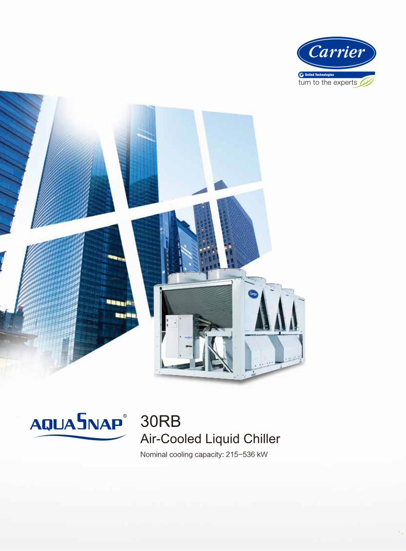
30RBAir-Cooled Liquid ChillerNominal cooling capacity: 215-536 kW

3
Founded by the inventor of modern air conditioning, Carrier is the world’s
leader in high-technology heating, air-conditioning and refrigeration solutions.
Carrier experts provide sustainable solutions, integrating energy-efficient
products, building controls and energy services for residential, commercial,
retail, transport and food service customers. Carrier is a part of UTC Build
ing & Industrial Systems, a unit of United Technologies Corp., a leading
provider to the aerospace and building systems industries worldwide.
With a broad portfolio of advanced technical patent awards, our global R&D
center in Shanghai develops innovative heat, ventilation and air-conditioning
(HVAC) solutions.
Turn To The Experts
In 1998, Time magazine named Dr. Carrier oneof its 20 most influential builders and titans ofthe 20thcentury.
2
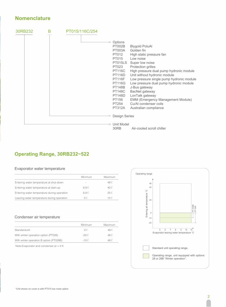
Operating Range, 30RB232~522
30RB232 B PT015/116C/254
Evaporator water temperature
Minimum Maximum
Entering water temperature at shut-down - 48℃
Entering water temperature at start-up 6.8℃ 40℃
Entering water temperature during operation 6.8℃ 25℃
Leaving water temperature during operation 5℃ 15℃
Condenser air temperature
Minimum Maximum
48℃0℃Standardunit
With winter operation option (PT028) -20℃ 48℃
With winter operation B option (PT028B) -10℃ 48℃
Operating range
Ent
erin
g ai
r tem
pera
ture
°C
Evaporator leaving water temperature °C
Note: Evaporator and condenser Δt = 5 K
*Unit shown on cover is with PT015 low noise option
Standard unit operating range.
5 6 7 8 9
-20
48
40
20
0
1510
-10
PT
028B
PT
028
Operating range, unit equipped with options 28 or 28B “Winter operation”.
Nomenclature
Options PT002B Blygold PoluAl PT003A Golden fin PT012 High static pressure fan PT015 Low noise PT015LS Super low noise PT023 Protection grilles PT116C High pressure dual pump hydronic module PT116D Unit without hydronic module PT116F Low pressure single pump hydronic module PT116G Low pressure dual pump hydronic module PT148B J-Bus gateway PT148C BacNet gateway PT148D LonTalk gateway PT156 EMM (Emergency Management Module) PT254 Cu/Al condenser coils PT312A Australian compliance
Design Series
Unit Model30RB Air-cooled scroll chiller
3
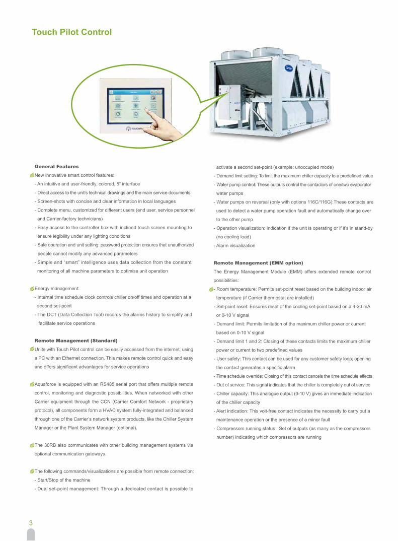
Touch Pilot Control
General Features
New innovative smart control features:
- An intuitive and user-friendly, colored, 5” interface
- Direct access to the unit’s technical drawings and the main service documents
- Screen-shots with concise and clear information in local languages
- Complete menu, customized for different users (end user, service personnel
and Carrier-factory technicians)
- Easy access to the controller box with inclined touch screen mounting to
ensure legibility under any lighting conditions
- Safe operation and unit setting: password protection ensures that unauthorized
people cannot modify any advanced parameters
- Simple and “smart” intelligence uses data collection from the constant
monitoring of all machine parameters to optimise unit operation
Energy management:
- Internal time schedule clock controls chiller on/off times and operation at a
second set-point
- The DCT (Data Collection Tool) records the alarms history to simplify and
facilitate service operations
Remote Management (Standard)
Units with Touch Pilot control can be easily accessed from the internet, using
a PC with an Ethernet connection. This makes remote control quick and easy
and offers significant advantages for service operations
Aquaforce is equipped with an RS485 serial port that offers multiple remote
control, monitoring and diagnostic possibilities. When networked with other
Carrier equipment through the CCN (Carrier Comfort Network - proprietary
protocol), all components form a HVAC system fully-integrated and balanced
through one of the Carrier’s network system products, like the Chiller System
Manager or the Plant System Manager (optional).
The 30RB also communicates with other building management systems via
optional communication gateways.
The following commands/visualizations are possible from remote connection:
- Start/Stop of the machine
- Dual set-point management: Through a dedicated contact is possible to
activate a second set-point (example: unoccupied mode)
- Demand limit setting: To limit the maximum chiller capacity to a predefined value
- Water pump control: These outputs control the contactors of one/two evaporator
water pumps
- Water pumps on reversal (only with options 116C/116G):These contacts are
used to detect a water pump operation fault and automatically change over
to the other pump
- Operation visualization: Indication if the unit is operating or if it’s in stand-by
(no cooling load)
- Alarm visualization
Remote Management (EMM option)
The Energy Management Module (EMM) offers extended remote control
possibilities:
- Room temperature: Permits set-point reset based on the building indoor air
temperature (if Carrier thermostat are installed)
- Set-point reset: Ensures reset of the cooling set-point based on a 4-20 mA
or 0-10 V signal
- Demand limit: Permits limitation of the maximum chiller power or current
based on 0-10 V signal
- Demand limit 1 and 2: Closing of these contacts limits the maximum chiller
power or current to two predefined values
- User safety: This contact can be used for any customer safety loop; opening
the contact generates a specific alarm
- Time schedule override: Closing of this contact cancels the time schedule effects
- Out of service: This signal indicates that the chiller is completely out of service
- Chiller capacity: This analogue output (0-10 V) gives an immediate indication
of the chiller capacity
- Alert indication: This volt-free contact indicates the necessity to carry out a
maintenance operation or the presence of a minor fault
- Compressors running status : Set of outputs (as many as the compressors
number) indicating which compressors are running
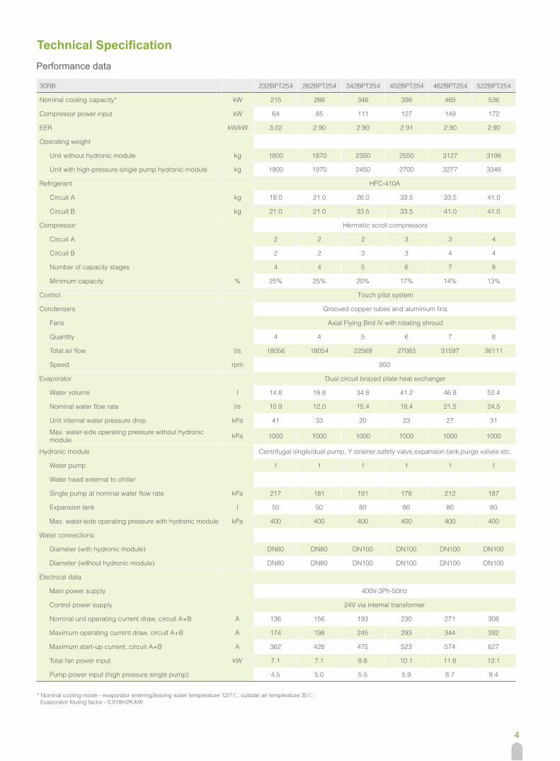
Performance data
4
Technical Specification
* Nominal cooling mode - evaporator entering/leaving water temperature 12/7℃, outside air temperature 35℃; Evaporator fouling factor - 0.018m2K/kW.
30RB 232BPT254 262BPT254 342BPT254 402BPT254 462BPT254 522BPT254
Nominal cooling capacity* kW 215 266 346 398 465 536
Compressor power input kW 64 85 111 127 149 172
EER kW/kW 3.02 2.90 2.90 2.91 2.90 2.90
Operating weight
Unit without hydronic module kg 1800 1870 2350 2550 3127 3198
Unit with high-pressure single pump hydronic module kg 1900 1970 2450 2700 3277 3348
Refrigerant HFC-410A
Circuit A kg 18.0 21.0 26.0 33.5 33.5 41.0
Circuit B kg 21.0 21.0 33.5 33.5 41.0 41.0
Compressor Hermetic scroll compressors
Circuit A 2 2 2 3 3 4
Circuit B 2 2 3 3 4 4
Number of capacity stages 4 4 5 6 7 8
Minimum capacity % 25% 25% 20% 17% 14% 13%
Control Touch pilot system
Condensers Grooved copper tubes and aluminium fins
Fans Axial Flying Bird IV with rotating shroud
Quantity 4 4 5 6 7 8
Total air flow I/s 18056 18054 22569 27083 31597 36111
Speed rpm 950
Evaporator Dual circuit brazed plate heat exchanger
Water volume I 14.8 18.8 34.8 41.2 46.8 52.4
Nominal water flow rate l/s 10.9 12.0 15.4 18.4 21.5 24.5
Unit internal water pressure drop kPa 41 33 20 23 27 31
Max. water-side operating pressure without hydronic module kPa 1000 1000 1000 1000 1000 1000
Hydronic module Centrifugal single/dual pump, Y strainer,safety valve,expansion tank,purge valves etc.
Water pump 1 1 1 1 1 1
Water head external to chiller
Single pump at nominal water flow rate kPa 217 181 191 178 212 187
Expansion tank I 50 50 80 80 80 80
Max. water-side operating pressure with hydronic module kPa 400 400 400 400 400 400
Water connections
Diameter (with hydronic module) DN80 DN80 DN100 DN100 DN100 DN100
Diameter (without hydronic module) DN80 DN80 DN100 DN100 DN100 DN100
Electrical data
Main power supply 400V-3Ph-50Hz
Control power supply 24V via internal transformer
Nominal unit operating current draw, circuit A+B A 136 156 193 230 271 308
Maximum operating current draw, circuit A+B A 174 198 245 293 344 392
Maximum start-up current, circuit A+B A 362 428 475 523 574 627
Total fan power input kW 7.1 7.1 8.6 10.1 11.6 13.1
Pump power input (high pressure single pump) 4.5 5.0 5.5 5.9 8.7 9.4
5
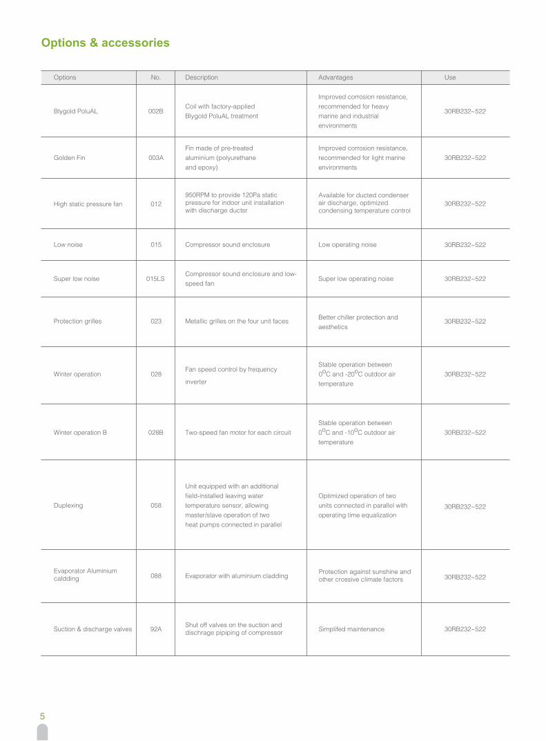
Options & accessories
Options
Blygold PoluAL
Golden Fin
Low noise
Super low noise
Protection grilles
Winter operation
Winter operation B
Duplexing
Evaporator Aluminiumcaldding
No.
002B
003A
015
015LS
023
028
028B
058
088
Description
Coil with factory-applied Blygold PoluAL treatment
Fin made of pre-treated aluminium (polyurethane and epoxy)
Compressor sound enclosure
Compressor sound enclosure and low-speed fan
Metallic grilles on the four unit faces
inverter
Fan speed control by frequency
Two-speed fan motor for each circuit
Unit equipped with an additional field-installed leaving water temperature sensor, allowing master/slave operation of two heat pumps connected in parallel
Evaporator with aluminium cladding
Advantages
Improved corrosion resistance, recommended for heavy marine and industrial environments
Improved corrosion resistance, recommended for light marine environments
Low operating noise
Super low operating noise
High static pressure fan 012950RPM to provide 120Pa static pressure for indoor unit installation with discharge ductsr
Available for ducted condenser air discharge, optimized condensing temperature control
Better chiller protection and aesthetics
Stable operation between 0oC and -20oC outdoor air temperature
Stable operation between 0oC and -10oC outdoor air temperature
Optimized operation of two units connected in parallel with operating time equalization
Protection against sunshine and other crossive climate factors
Use
30RB232~522
30RB232~522
30RB232~522
30RB232~522
30RB232~522
30RB232~522
30RB232~522
30RB232~522
30RB232~522
30RB232~522
Suction & discharge valves 92AShut off valves on the suction and dischrage pipiping of compressor Simplifed maintenance 30RB232~522
6
Options & accessories
Options
Unit without hydronic module
Low pressure single pump hydronic module
Low pressure dual pump hydronic module
J-Bus gateway
BacNet gateway
LonTalk gateway
Energy Management Module (EMM)
Cu/Al condenser coils
Australian compliance
No.
116D
116F
116G
148B
148C
148D
156
254
312A
Description
Flexible for customer to purchase and install the water components by themselves
Provide integrated hydronic module with low pressure single pump
Provide integrated hydronic module with low pressure dual pump
Two-directional communication board with J-Bus protocol
Two-directional communication board with BacNet protocol
Two-directional communication board with LonTalk protocol
See control manual
Coils made of copper tube with aluminium fin
Compliance with Australian regulation
Advantages
-
Easy and fast installation
Easy and fast installation, operating safety
Easy connection by communication bus to building management system
Easy connection by communication bus to building management system
Easy connection by communication bus to building management system
-
-
-
Use
30RB232~522
30RB232~522
30RB232~522
30RB232~522
30RB232~522
30RB232~522
30RB232~522
30RB232~522
30RB232~522
High pressure dual pump hydronic module
116CProvide integrated hydronic module with high pressure dual pump
Easy and fast installation, operating safety
30RB232~522
Discharge valve 93A Shut off valves on the dischrage pipiping of compressor Simplifed maintenance 30RB232~522
7
Dimensions/Clearances
30RB232/30RB262
Unit model
30RB232
30RB262
X(mm)
1180
1210
Y(mm)
1270
1294
Z(mm)
1150
1081
2
1 Required clearances for maintenance
Power electrical box
3 Safety valve
Water inlet
Water outlet
Power supply connection
Center gravity
Air outlet
Legend:
Note:30RB232/262 single power connection point, and arrive from the bottom. All dimensions are given in mm.
608
X2410
1500
1500
2200
750 368
247
3
2
1
1
1 1
DN80
878Power supplyconnection
637 979
Y
Z
2253
Right view
DN80
1500
2297
1194
8
Dimensions/Clearances
30RB342/30RB402
2
1 Required clearances for maintenance
Power electrical box
3 Safety valve
Water inlet
Water outlet
Power supply connection
Center gravity
Air outlet
Legend:
Note:30RB342/402 single power connection point, and arrive from the bottom. All dimensions are given in mm.
Unit model
30RB342
30RB402
X(mm)
1823
1828
Y(mm)
1277
1288
Z(mm)
889
893
A(mm)
868
1068
1
1
11
3
1500
1500
2200
DN100
DN100
750
A
639 979
Y
Z
2253
368
247
Power supplyconnection
Right view
608
2297
3604X
1194 1194
9
Dimensions/Clearances
30RB462/30RB522
Unit model
30RB462
30RB522
X(mm)
2514
2637
Y(mm)
1308
1326
Z(mm)
932
961
Power supplyconnection
Right view
2
1
1
3
1
1
637 979
1069Y
2253
DN100
DN100
4798
X
2297
608 1194 1194 1194
15001500
1500 2200
247
750 368
Note:30RB462/522 single power connection point, and arrive from the bottom. All dimensions are given in mm.
2
1 Required clearances for maintenance
Power electrical box
3 Safety valve
Water inlet
Water outlet
Power supply connection
Center gravity
Air outlet
Legend:
10
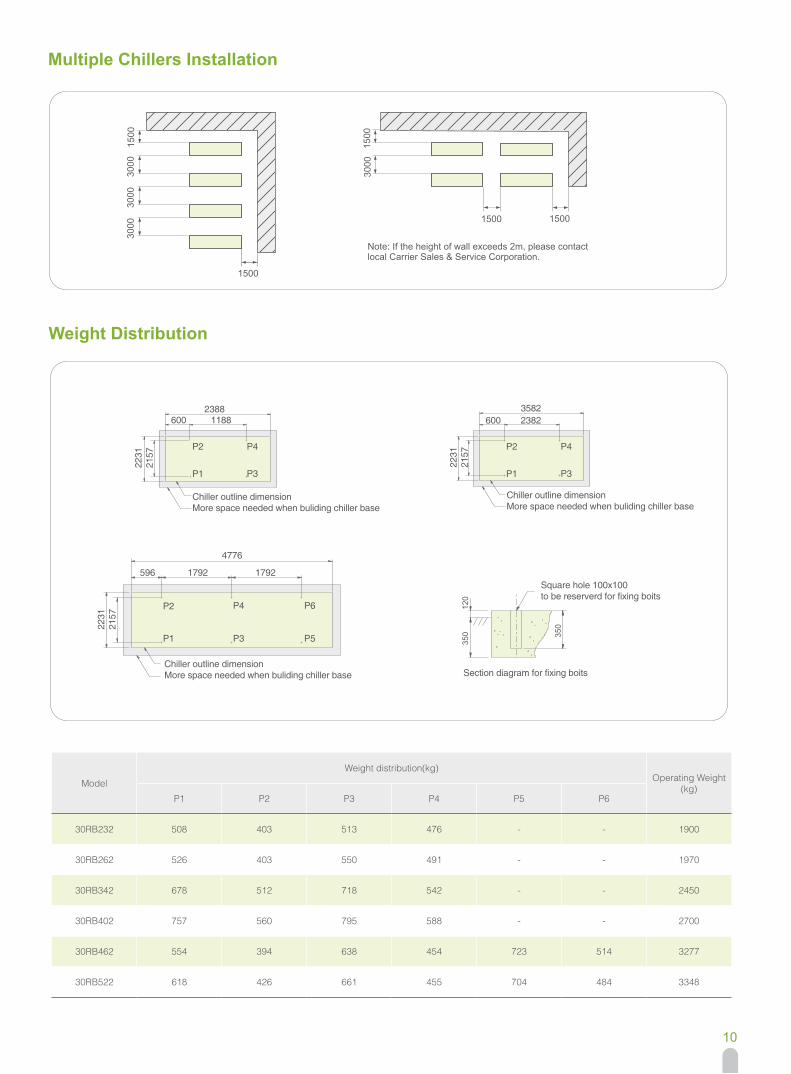
2388 3582600 2382
2231
2157
2231
2157
P2
P1
P4
P3
P2
P1
P4
4776
2231
2157
596 1792 1792
P3
P6
P5
P2
P1
P4
P3
Chiller outline dimension More space needed when buliding chiller base
Chiller outline dimension More space needed when buliding chiller base
Chiller outline dimension More space needed when buliding chiller base
Section diagram for fixing boits
Square hole 100x100to be reserverd for fixing boits
350
12
0
350
600 1188
Multiple Chillers Installation
Weight Distribution
3000
1500
3000
3000
1500
3000
1500
15001500
Note: If the height of wall exceeds 2m, please contactlocal Carrier Sales & Service Corporation.
Model
Weight distribution(kg)Operating Weight
(kg)P1 P2 P3 P4 P5 P6
30RB232 508 403 513 476 - - 1900
30RB262 526 403 550 491 - - 1970
30RB342 678 512 718 542 - - 2450
30RB402 757 560 795 588 - - 2700
30RB462 554 394 638 454 723 514 3277
30RB522 618 426 661 455 704 484 3348
11
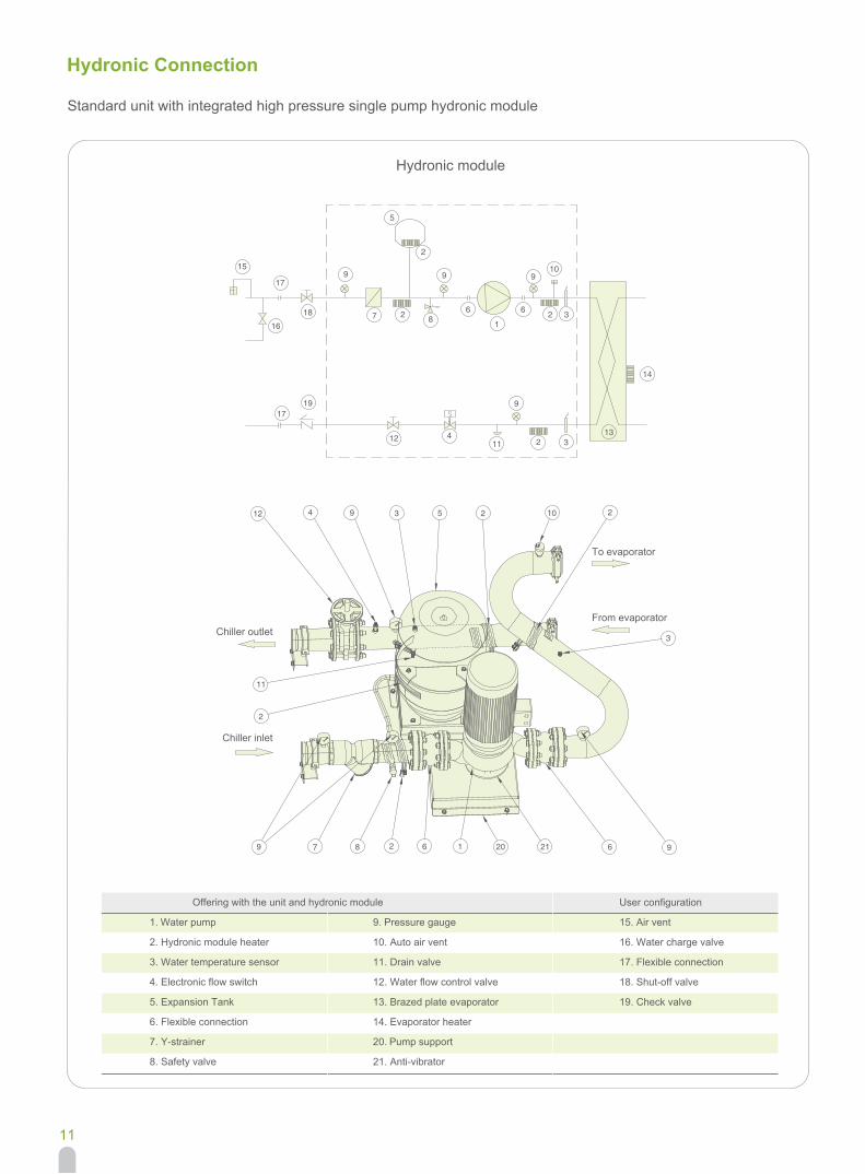
Hydronic Connection
Standard unit with integrated high pressure single pump hydronic module
Hydronic module
15
17
16
1719
12 411 2 3
9
13
14
18
9
5
27
2
9
8
910
3266
1
Offering with the unit and hydronic module
2. Hydronic module heater
1. Water pump
3. Water temperature sensor
4. Electronic flow switch
5. Expansion Tank
6. Flexible connection
7. Y-strainer
8. Safety valve
9. Pressure gauge
10. Auto air vent
11. Drain valve
12. Water flow control valve
13. Brazed plate evaporator
14. Evaporator heater
21. Anti-vibrator
20. Pump support
User configuration
15. Air vent
16. Water charge valve
17. Flexible connection
18. Shut-off valve
19. Check valve
To evaporator
From evaporatorChiller outlet
Chiller inlet
20
12
7
5
62
4 9 3
3
10
8
11
2
2 2
91 2169

12
3
Heat Exchanger Water Pressure Drop
1 30RB232
30RB262
30RB342
30RB402
30RB462
30RB522
2
3
4
5
6
1 30RB232
30RB262
30RB342
30RB402
30RB462
30RB522
2
3
4
5
6
56
30RB23230RB26230RB34230RB40230RB46230RB522
21
4
Available Static Pressure
Low pressure single pump hydronic module
High pressure single pump hydronic module
①
①
①
160
140
120
100
80
60
40
20
0
300
250
200
150
100
50
0
350
300
250
200
150
100
50
0
0 20 40 60 80 100 120 140 160
0 20 40 60 80 100
0 20 40 60 80 100 120
Pres
sure
dro
p (k
Pa)
Avai
labl
e st
atic
pre
ssur
e (k
Pa)
Avai
labl
e st
atic
pre
ssur
e (k
Pa)
Water flow (m³/h)
②
②
②
③
③
③
④
④
④
⑤
⑤
⑤
⑥
⑥
⑥
Water flow (m³/h)
Water flow (m³/h)
13
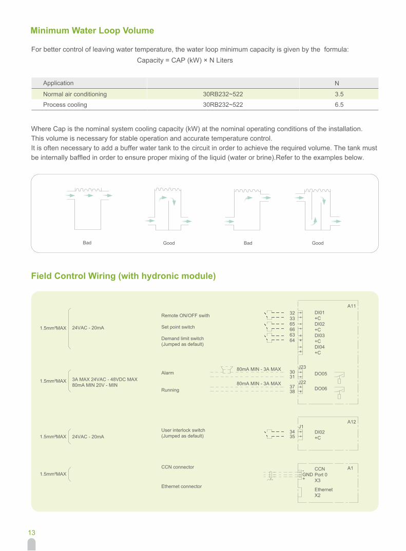
Minimum Water Loop Volume
Field Control Wiring (with hydronic module)
For better control of leaving water temperature, the water loop minimum capacity is given by the formula: Capacity = CAP (kW) × N Liters
Application
Normal air conditioning
Process cooling
Bad Good Bad Good
N
3.5
6.5
30RB232~522
30RB232~522
Where Cap is the nominal system cooling capacity (kW) at the nominal operating conditions of the installation.This volume is necessary for stable operation and accurate temperature control.It is often necessary to add a buffer water tank to the circuit in order to achieve the required volume. The tank must be internally baffled in order to ensure proper mixing of the liquid (water or brine).Refer to the examples below.
1.5mm²MAX
1.5mm²MAX
24VAC - 20mA
3A MAX 24VAC - 48VDC MAX80mA MIN 20V - MIN
24VAC - 20mA
Remote ON/OFF swith
Set point switch
Demand limit switch(Jumped as default)
Alarm
Running
User interlock switch(Jumped as default)
CCN connector
Ethernet connector
DI01+CDI02+CDI03+CDI04+C
DO05
DO06
DI02+C
CCNPort 0X3
EthernetX2
80mA MIN - 3A MAX
80mA MIN - 3A MAX
A11
J1
J23
J22
A12
A1
323365666364
3031
3738
3435
-GND+
1.5mm²MAX
1.5mm²MAX
CAT_30RB(T)_E-1406_01
-
Jun, 2014
The Manufacturer reserves the right to change any produt specifications without prior notices Version:
Supersede:
Effective Date: