Embed Size (px)
Citation preview

E 479/579 Mechatronics Modeling and Simulation
TO STUDY THE DEFLECTION OF MEMS ETM ACTUATOR BY
USING 20-Sim
- CHANDRASEKHARAN SRINIVASAN

E 479/579 Mechatronics Modeling and Simulation
IntroductionElectro-Thermo-Mechanical Actuators
FEA Analysis
20-Sim model of an actuator
Actuator array
Simulation results
Validation

E 479/579 Mechatronics Modeling and Simulation
INTRODUCTION
An simple one element Electro thermal mechanical actuator was modeled in 20-sim.
Electrical voltage is given as input so as to get the deflection as the output.
Modeled for a 3x2 ETM actuator array. The deflection output is validated with the results
obtained from the reference papers.

E 479/579 Mechatronics Modeling and Simulation
Introduction Electro-Thermo-
Mechanical ActuatorsFEA Analysis20-Sim model of an actuatorActuator arraySimulation resultsValidation

E 479/579 Mechatronics Modeling and Simulation
Types of ETM actuators
Single ‘hot’ arm ETM actuator
Double ‘hot’ arm ETM actuator
Bi-directional Vertical thermal actuator (BVTA)
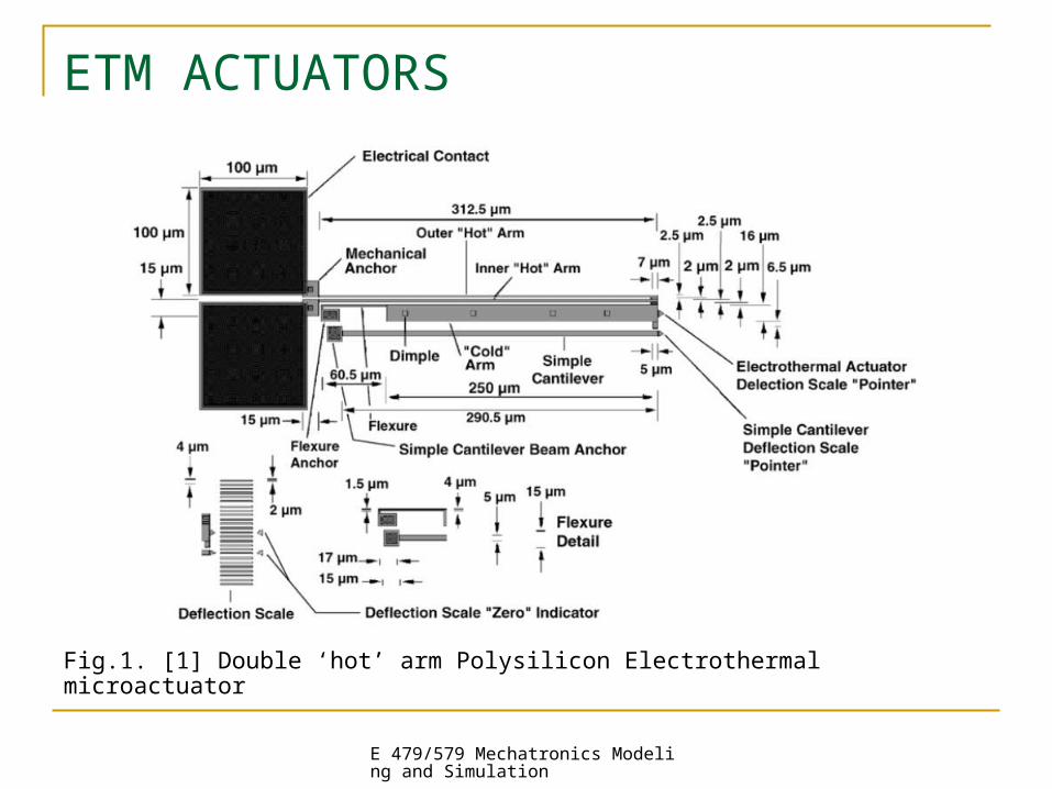
ETM ACTUATORS
E 479/579 Mechatronics Modeling and Simulation
ETM ACTUATORS
Fig.1. [1] Double ‘hot’ arm Polysilicon Electrothermal microactuator

E 479/579 Mechatronics Modeling and Simulation
PRINCIPLE OF OPERATION
Input:Electrical voltage or
current
Heat generation causes
temperature increase
Expansion of heated parts of
actuator
Generation of thermal stresses and mechanical
force
Mechanical force carries out
the required mech. work

E 479/579 Mechatronics Modeling and Simulation
Introduction
Electro-Thermo-Mechanical Actuators
FEA Analysis20-Sim model of an actuator
Actuator array
Simulation results
Validation

E 479/579 Mechatronics Modeling and Simulation
FEA ANALYSIS

E 479/579 Mechatronics Modeling and Simulation
FEA ANALYSIS
The FEA analysis using ABAQUS had to be aborted because of the following reasons:
1. Lots of errors
2. Missing out on few parameters
The research on the FEA analysis will be continued.

E 479/579 Mechatronics Modeling and Simulation
Introduction
Electro-Thermo-Mechanical Actuators
FEA Analysis
20-Sim model of an actuatorActuator array
Simulation results
Validation

E 479/579 Mechatronics Modeling and Simulation
20-Sim BONDGRAPH MODEL OF A SINGLE ACTUATOR
Imass
MSeMSe3
GYGY3
0
Cstiffness
1
Rdamping
Constant1
Integrate1
r

E 479/579 Mechatronics Modeling and Simulation
Constant wave generator for voltage input (1-10 volts) MSe, the effort is set to the constant input signal source Gyrator to transform the effort coming in (voltage) into flow
going out. r, Gyrator modulus ( or the multiplying factor to get the
deflection) R, damping C, stiffness I, Moving mass of the element Integrator to get the deflection output

E 479/579 Mechatronics Modeling and Simulation
Introduction
Electro-Thermo-Mechanical Actuators
FEA Analysis
20-Sim model of an actuator
Actuator arraySimulation results
Validation

E 479/579 Mechatronics Modeling and Simulation
ACTUATOR ARRAY
An Integrated ETM device with 3 X 2 arrayRef. paper [ 4 ]
3x2 array of actuators3x2 array of actuators The width of the narrow beam is The width of the narrow beam is
3030μμm-40m-40μμmm Material properties of polysiliconMaterial properties of polysilicon The effective moving massThe effective moving mass
is 6.75eis 6.75e-12 -12 kgkg

E 479/579 Mechatronics Modeling and Simulation
20-Sim MODEL OF AN ACTUATOR ARRAY
IMoving_Mass
MSeMSe3
GYGY3
GYGY4
0
MSeMSe4
CStiffness
1
RDamping
MSeMSe5
GYGY5
MSeMSe6
GYGY6
MSeMSe2
GYGY2
MSeMSe1
GYGY1
Voltage_Input
Deflection_Output

E 479/579 Mechatronics Modeling and Simulation
Introduction
Electro-Thermo-Mechanical Actuators
FEA Analysis
20-Sim model of an actuator
Actuator array
Simulation resultsValidation

E 479/579 Mechatronics Modeling and Simulation
Deflection vs Voltage
0 1 2 3 4 5 6 7 8 9 10time {s}
0
5e-007
1e-006
1.5e-006
Deflection
Deflection vs Time
0 1 2 3 4 5 6 7 8 9 10time {s}
-2e-007
0
2e-007
4e-007
6e-007
8e-007Deflection
Voltage Input: 2v
Deflection: 0.5537
Voltage Input: 4v
Deflection: 1.7345
m
m

E 479/579 Mechatronics Modeling and Simulation
Deflection vs Voltage
0 1 2 3 4 5 6 7 8 9 10time {s}
0
1e-006
2e-006
3e-006
4e-006
Deflection
Deflection vs Voltage
0 1 2 3 4 5 6 7 8 9 10time {s}
0
2e-006
4e-006
6e-006
8e-006
Deflection
Voltage Input: 6v
Deflection: 3.7476
Voltage Input: 8v
Deflection: 7.0330
m
m

E 479/579 Mechatronics Modeling and Simulation
Introduction
Electro-Thermo-Mechanical Actuators
FEA Analysis
20-Sim model of an actuator
Actuator array
Simulation results
Validation

E 479/579 Mechatronics Modeling and Simulation
VALIDATION OF RESULTSVoltage
Input20-Sim Results
Validated result
0 0 0
1 0.2338 -
2 0.5537 0.55
3 1.0401 1.1
4 1.7345 1.76
5 2.5079 2.53
6 3.7476 3.74
7 5.1355 5.17
8 7.033 6.93
9 8.9619 8.8
Deflection vs Voltage plot. Ref. paper [2]
Results validated in reference to the paper [2]

E 479/579 Mechatronics Modeling and Simulation
VALIDATION OF RESULTS
Deflection vs Voltage
0
1
2
3
4
5
6
7
8
9
10
0 1 2 3 4 5 6 7 8 9
Voltage ( Volt )
De
fle
cti
on
( m
icro
me
ter)
20-Sim Results
Validated result
The above plot shows the change in deflection of the actuator at different voltages

E 479/579 Mechatronics Modeling and Simulation
CONCLUSION
The simulation results obtained from 20-Sim are in good agreement with the results in the reference paper [2].
The deflection results of a single ETM actuator were similar to that of the actuator array

E 479/579 Mechatronics Modeling and Simulation
EXTENSION
Complete the FEA analysis on the ETM actuator and compare it with the 20-Sim results.
To research on the fact that the ETM actuator gets destroyed when the applied voltage reaches 10 volts.

E 479/579 Mechatronics Modeling and Simulation
REFERENCES
1. “Design and modeling of a MEMS bidirectional vertical thermal actuator”
-Dong Yan, Amir Khajepour and Raafat Mansour
2. “Experimentally verified procedure for determining dynamical model of the ETM MEMS structures” – Dept. of Engineering, Univ. of Texas, Arlington.
3. “Electrothermal MEMS microengine capable of bi-directional motion” - Dept. of Engineering, Tucker Technology center, Texas
4. “Effect of Thermal Boundary condition and scaling on Electro-Thermal compliant micro devices” – Nilesh Mankane and G.K. Ananthasuresh
5. “System Dynamics: Modeling and Simulation of Mechatronic systems” – Karnopp, Margolis and Rosenberg

E 479/579 Mechatronics Modeling and Simulation
THANK YOU