Embed Size (px)
Citation preview
1
STUDY OF HYBRID ENERGY SYSTEM BASED
ON WIND-DIESEL ENGINE SYSTEM
SAMRESH SATAPATHY (110EE0227)
Department of Electrical Engineering,
National Institute of Technology, Rourkela
2
STUDY OF HYBRID ENERGY SYSTEM BASED
ON WIND-DIESEL ENGINE SYSTEM
A Thesis submitted in partial fulfillment of the requirements for the degree of
Bachelor of Technology in “Electrical Engineering”
By
SAMRESH SATAPATHY (110EE0227)
Under the guidance of
Prof. P.C Panda
Department of Electrical Engineering
National Institute of Technology
Rourkela-769008 (Odisha)

3
DEPARTMENT OF ELECTRICAL ENGINEERING
NATIONAL INSTITUTE OF TECHNOLOGY, ROURKELA- 769008
ODISHA, INDIA
CERTIFICATE
This is to certify that the thesis titled “Study of Hybrid Energy System based on Wind-Diesel
Engine System”, submitted to National Institute of Technology, Rourkela by Mr. Samresh
Satapathy, Roll No. : 110EE0227 for the award of Bachelor of Technology in Electrical
Engineering is a bonafide record of research work carried out by him under my supervision and
guidance.
The candidate has fulfilled all the prescribed requirements.
The thesis which is based on the candidate’s own work, has not been submitted elsewhere for a
degree/diploma.
In my opinion, the thesis is of standard required for the award of a Bachelor of Technology in
Electrical Engineering.
Prof. P.C Panda
Supervisor
Department of Electrical Engineering
National Institute of Technology
Rourkela-769008 (Odisha)

4
ACKNOWLEDGEMENTS
I have been highly indebted in the preparation of this report to my supervisor, Prof. P.C
Panda, whose patience and kindness, as well as his academic experience, has been invaluable to
me. I could not have asked for a better role model, inspirational, supportive, and patient guide.
The insightful comments and suggestions provided by him were really helpful.
I would also like to thank Prof. A.K. Panda, HOD, Department of Electrical Engineering,
NIT Rourkela for his initial guidance and motivation to work on distributed generation and
renewable energy. I would also like to express my gratitude to Prof. William David Lubitz,
University of Guelph, Canada for helping me with the wind data necessary for simulation of
the wind turbine. The informal support and encouragement of many friends has been
indispensable.
I am blessed by my parents, who instilled within me a love of creative pursuits, science and
language, all of which finds a place in this report.
Samresh Satapathy
110EE0227

5
With Blessings from Almighty
Dedicated to
My Parents.
6
ABSTRACT
The aggravated increase in energy demand has posed a serious problem for the power
system’s stability and reliability, and hence has become of major concern. The shortcomings of
conventional source of energy have paved way for renewable energy sources. The latter can form
a part of a stand-alone system or grid connected system. A single renewable source of energy
when integrated with other sources of energy it is termed as hybrid system. This thesis deals with
wind-diesel engine system. Wind diesel hybrid systems (WDHS) obtain maximum contribution
from wind and rest by diesel generators. They are handy for rural or island areas.
In this thesis an active power control strategy has been developed such that when the wind
alone is not able to meet the energy demand, without compromising the frequency a transition
occurs to wind diesel mode so that the energy demand is met. Then the system’s dynamic
performance is compared for two cases with squirrel cage induction generator and permanent
magnet induction generator. The mathematical model considered uses a STATCOM to meet the
reactive power need upon sudden step change in power. The performance and the analysis is
done in a user friendly MATLAB/Simulink environment.
7
CONTENTS
Abstract…………………………………………………………………………………………...6
Contents…………………………………………………………………………………………..7
List of Figures…………………………………………………………………………………….9
List of Tables……………………………………………………………………………………10
Abbreviations and Acronyms………………………………………………………………….11
CHAPTER 1
INTRODUCTION
1.1 Motivation……………………………………………………………………………………13
1.2 Background and Literature Review…………………………………………………………14
1.3 Thesis Objectives……………………………………………………………………………15
1.4 Organization of Thesis………………………………………………………………………15
CHAPTER 2
TRANSITION FROM WO MODE TO WD MODE
2.1 Introduction………………………………………………………………………………….18
2.2 System Layout……………………………………………………………………………….18
2.3 Distributed Control System………………………………………………………………….19
2.4 Simulink Model……………………………………………………………………………...21
2.5 Simulation Results…………………………………………………………………………...25
2.6 Conclusion…………………………………………………………………………………...26
8
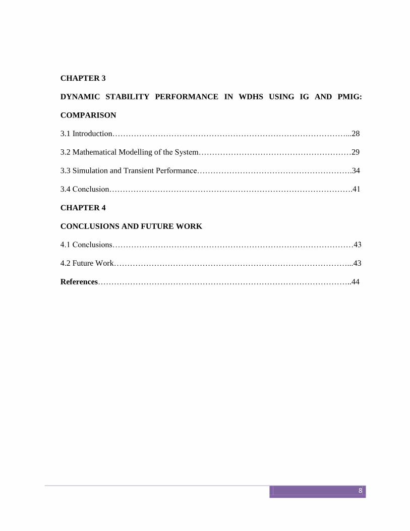
CHAPTER 3
DYNAMIC STABILITY PERFORMANCE IN WDHS USING IG AND PMIG:
COMPARISON
3.1 Introduction……………………………………………………………………………...28
3.2 Mathematical Modelling of the System…………………………………………………29
3.3 Simulation and Transient Performance………………………………………………….34
3.4 Conclusion……………………………………………………………………………….41
CHAPTER 4
CONCLUSIONS AND FUTURE WORK
4.1 Conclusions………………………………………………………………………………43
4.2 Future Work……………………………………………………………………………...43
References…………………………………………………………………………………..44
9
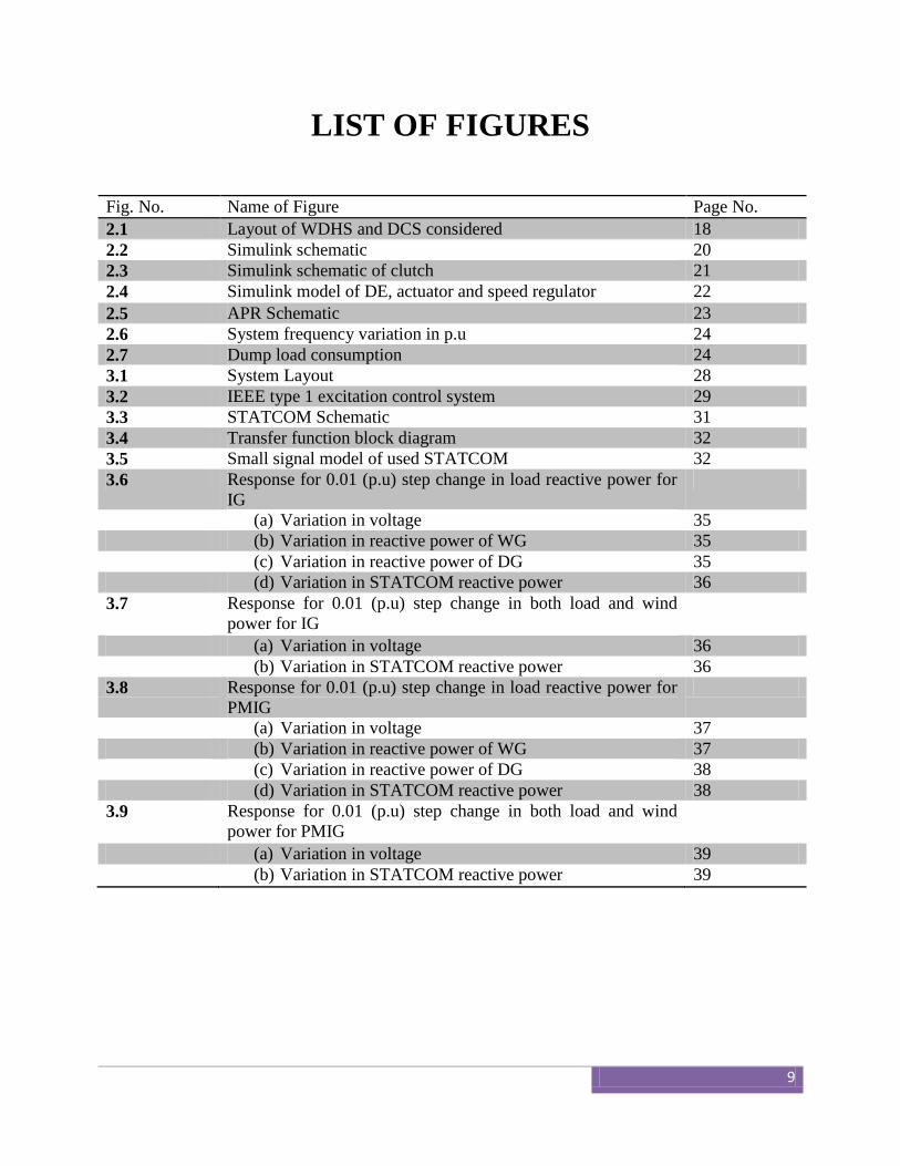
LIST OF FIGURES
Fig. No. Name of Figure Page No.
2.1 Layout of WDHS and DCS considered 18
2.2 Simulink schematic 20
2.3 Simulink schematic of clutch 21
2.4 Simulink model of DE, actuator and speed regulator 22
2.5 APR Schematic 23
2.6 System frequency variation in p.u 24
2.7 Dump load consumption 24
3.1 System Layout 28
3.2 IEEE type 1 excitation control system 29
3.3 STATCOM Schematic 31
3.4 Transfer function block diagram 32
3.5 Small signal model of used STATCOM 32
3.6 Response for 0.01 (p.u) step change in load reactive power for
IG
(a) Variation in voltage 35
(b) Variation in reactive power of WG 35
(c) Variation in reactive power of DG 35
(d) Variation in STATCOM reactive power 36
3.7 Response for 0.01 (p.u) step change in both load and wind
power for IG
(a) Variation in voltage 36
(b) Variation in STATCOM reactive power 36
3.8 Response for 0.01 (p.u) step change in load reactive power for
PMIG
(a) Variation in voltage 37
(b) Variation in reactive power of WG 37
(c) Variation in reactive power of DG 38
(d) Variation in STATCOM reactive power 38
3.9 Response for 0.01 (p.u) step change in both load and wind
power for PMIG
(a) Variation in voltage 39
(b) Variation in STATCOM reactive power 39
10
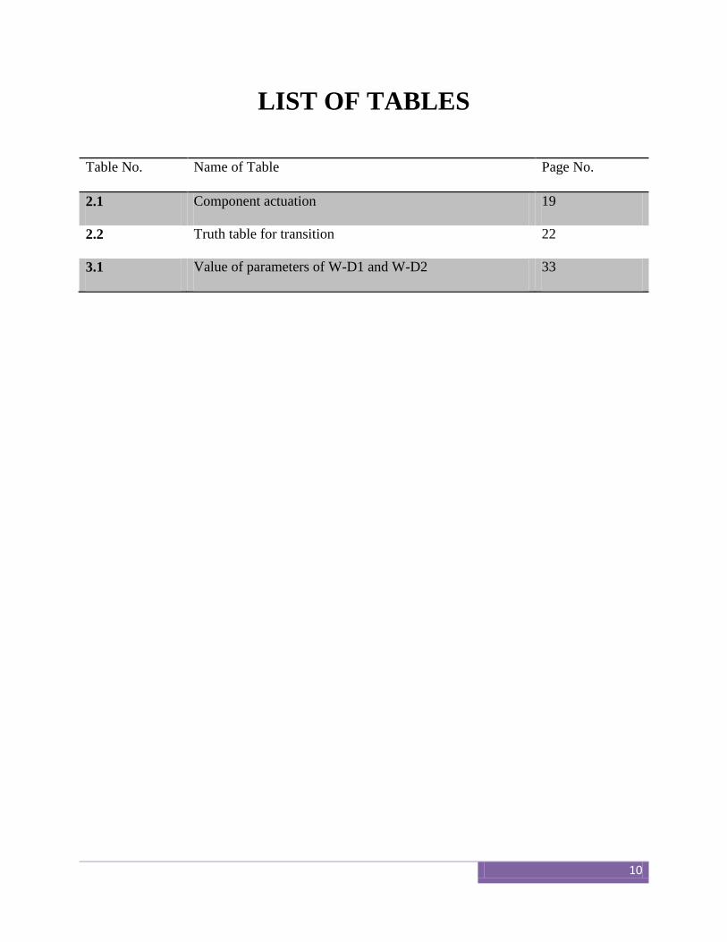
LIST OF TABLES
Table No. Name of Table Page No.
2.1 Component actuation 19
2.2 Truth table for transition 22
3.1 Value of parameters of W-D1 and W-D2 33
11
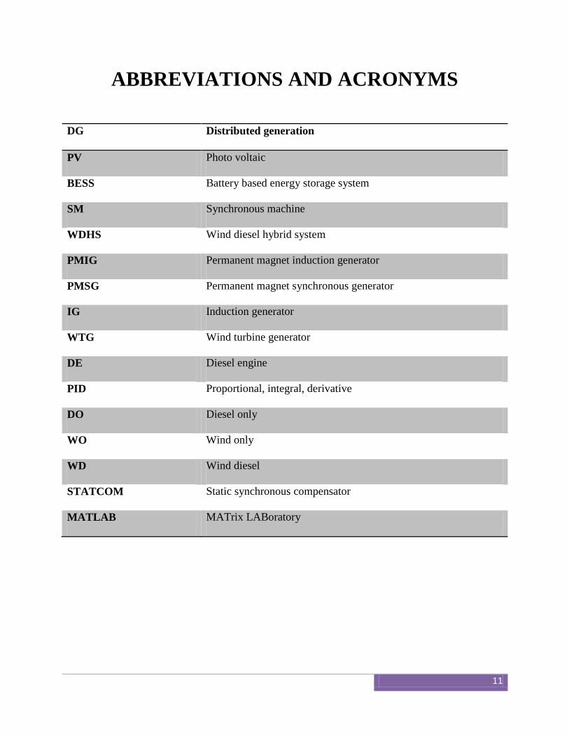
ABBREVIATIONS AND ACRONYMS
DG Distributed generation
PV Photo voltaic
BESS Battery based energy storage system
SM Synchronous machine
WDHS Wind diesel hybrid system
PMIG Permanent magnet induction generator
PMSG Permanent magnet synchronous generator
IG Induction generator
WTG Wind turbine generator
DE Diesel engine
PID Proportional, integral, derivative
DO Diesel only
WO Wind only
WD Wind diesel
STATCOM Static synchronous compensator
MATLAB MATrix LABoratory

12
CHAPTER 1
Introduction
13
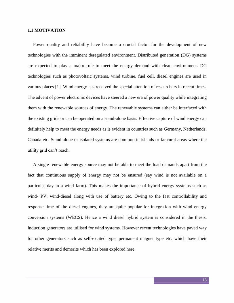
1.1 MOTIVATION
Power quality and reliability have become a crucial factor for the development of new
technologies with the imminent deregulated environment. Distributed generation (DG) systems
are expected to play a major role to meet the energy demand with clean environment. DG
technologies such as photovoltaic systems, wind turbine, fuel cell, diesel engines are used in
various places [1]. Wind energy has received the special attention of researchers in recent times.
The advent of power electronic devices have steered a new era of power quality while integrating
them with the renewable sources of energy. The renewable systems can either be interfaced with
the existing grids or can be operated on a stand-alone basis. Effective capture of wind energy can
definitely help to meet the energy needs as is evident in countries such as Germany, Netherlands,
Canada etc. Stand alone or isolated systems are common in islands or far rural areas where the
utility grid can’t reach.
A single renewable energy source may not be able to meet the load demands apart from the
fact that continuous supply of energy may not be ensured (say wind is not available on a
particular day in a wind farm). This makes the importance of hybrid energy systems such as
wind- PV, wind-diesel along with use of battery etc. Owing to the fast controllability and
response time of the diesel engines, they are quite popular for integration with wind energy
conversion systems (WECS). Hence a wind diesel hybrid system is considered in the thesis.
Induction generators are utilised for wind systems. However recent technologies have paved way
for other generators such as self-excited type, permanent magnet type etc. which have their
relative merits and demerits which has been explored here.
14
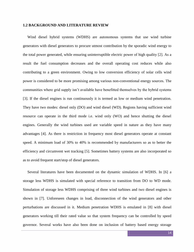
1.2 BACKGROUND AND LITERATURE REVIEW
Wind diesel hybrid systems (WDHS) are autonomous systems that use wind turbine
generators with diesel generators to procure utmost contribution by the sporadic wind energy to
the total power generated, while ensuring uninterruptible electric power of high quality [2]. As a
result the fuel consumption decreases and the overall operating cost reduces while also
contributing to a green environment. Owing to low conversion efficiency of solar cells wind
power is considered to be more promising among various non-conventional energy sources. The
communities where grid supply isn’t available have benefitted themselves by the hybrid systems
[3]. If the diesel engines is run continuously it is termed as low or medium wind penetration.
They have two modes: diesel only (DO) and wind diesel (WD). Regions having sufficient wind
resource can operate in the third mode i.e. wind only (WO) and hence shutting the diesel
engines. Generally the wind turbines used are variable speed in nature as they have many
advantages [4]. As there is restriction in frequency most diesel generators operate at constant
speed. A minimum load of 30% to 40% is recommended by manufacturers so as to better the
efficiency and circumvent wet tracking [5]. Sometimes battery systems are also incorporated so
as to avoid frequent start/stop of diesel generators.
Several literatures have been documented on the dynamic simulation of WDHS. In [6] a
storage less WDHS is simulated with special reference to transition from DO to WD mode.
Simulation of storage less WDHS comprising of three wind turbines and two diesel engines is
shown in [7]. Unforeseen changes in load, disconnection of the wind generators and other
perturbations are discussed in it. Medium penetration WDHS is emulated in [8] with diesel
generators working till their rated value so that system frequency can be controlled by speed
governor. Several works have also been done on inclusion of battery based energy storage
15
(BESS) and inclusion of flywheels while transition from one mode to the other. The former
while incorporates an ac/dc interface; the latter has advantages due to the fact that energy can
directly be stored in ac form and hence eliminating the converter losses. However battery
systems have their own advantage of better smoothing out transitions and provide power when
there is an energy shortage.
1.3 THESIS OBJECTIVES
The objectives below are hopefully achieved in the thesis.
To design a WDHS in MATLAB/Simulink environment.
To analyze and design a control system for smooth change from WO to WD mode so that
the system constraints are met.
To develop a mathematical model of induction generator (IG) and permanent magnet
induction generator (PMIG) for small signal analysis.
To compare the performance of IG and PMIG for various loadings through simulations in
MATLAB/Simulink environment.
1.4 ORGANISATION OF THESIS
The thesis has been organized into four chapters. The individual chapters are different from
each other and are described with ample theory to grasp it and understand the simulations.
Chapter 2 deals with the basic WDHS system that exists in far communities. An appropriate
control strategy has been designed for the regulation of active power and hence the frequency.
The system is a high penetration system and hence a smooth shift from WO to WD mode is
prophesized when there is sudden increase in load demand. Modelling of clutch is also described
which helps to engage/disengage the diesel generators. A dump load has also been introduced
16
which can take care of extra power generated and hence not to lead to over frequency.
Simulation results have been then analyzed to check the validity of the control strategy.
Chapter 3 then deals with the performance investigation of the stand-alone WDHS. While
the previous chapter was worked with IG, here a comparative study is done with the usage of IG
and PMIG. To study the relative merits/demerits two different loading conditions are compared.
First the mathematical model is developed based on small signal model. A STATCOM has been
incorporated which helps to reduce the reactive power mismatch. This is essential as reactive
power level decides the system voltage stability. The model is then simulated in
MATLAB/Simulink and the results are analyzed.
Chapter 4 concludes the work and enlists the future work for the same. Some possible
limitations in the work have also been provided. The future work that can be done to improvise
the current scenario is also mentioned.

17
CHAPTER 2
Transition from WO mode to WD mode
18
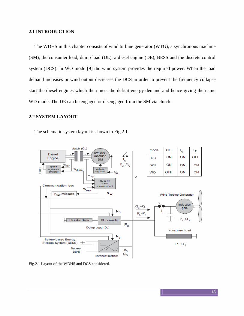
2.1 INTRODUCTION
The WDHS in this chapter consists of wind turbine generator (WTG), a synchronous machine
(SM), the consumer load, dump load (DL), a diesel engine (DE), BESS and the discrete control
system (DCS). In WO mode [9] the wind system provides the required power. When the load
demand increases or wind output decreases the DCS in order to prevent the frequency collapse
start the diesel engines which then meet the deficit energy demand and hence giving the name
WD mode. The DE can be engaged or disengaged from the SM via clutch.
2.2 SYSTEM LAYOUT
The schematic system layout is shown in Fig 2.1.
Fig.2.1 Layout of the WDHS and DCS considered.
19
The clutch with the help of friction gets locked and do not slip. It helps to transmit torque to
the SM from DE. Due to the isochronous nature of DE it runs at constant speed. The WTG
consists of IG which runs as a constant speed stall-controlled system. The compensation
capacitor bank aids for reactive power consumption by the IG. The DL which consists of a bank
of resistors varies discreetly and is a controllable absorber of active power. However the BESS
can act as a source or sink of active power depending on the operating conditions. The
DL+BESS system perform instantaneous power balance by loading when wind power is in
excess and by generating power when it is deficit. The power produced by WTG, PT plus BESS
power PS-NOM must be greater than load power PL. When the constraint does not meet then the
DCS starts the DE leading to WD. In this thesis it is assumed that the BESS operates at unity
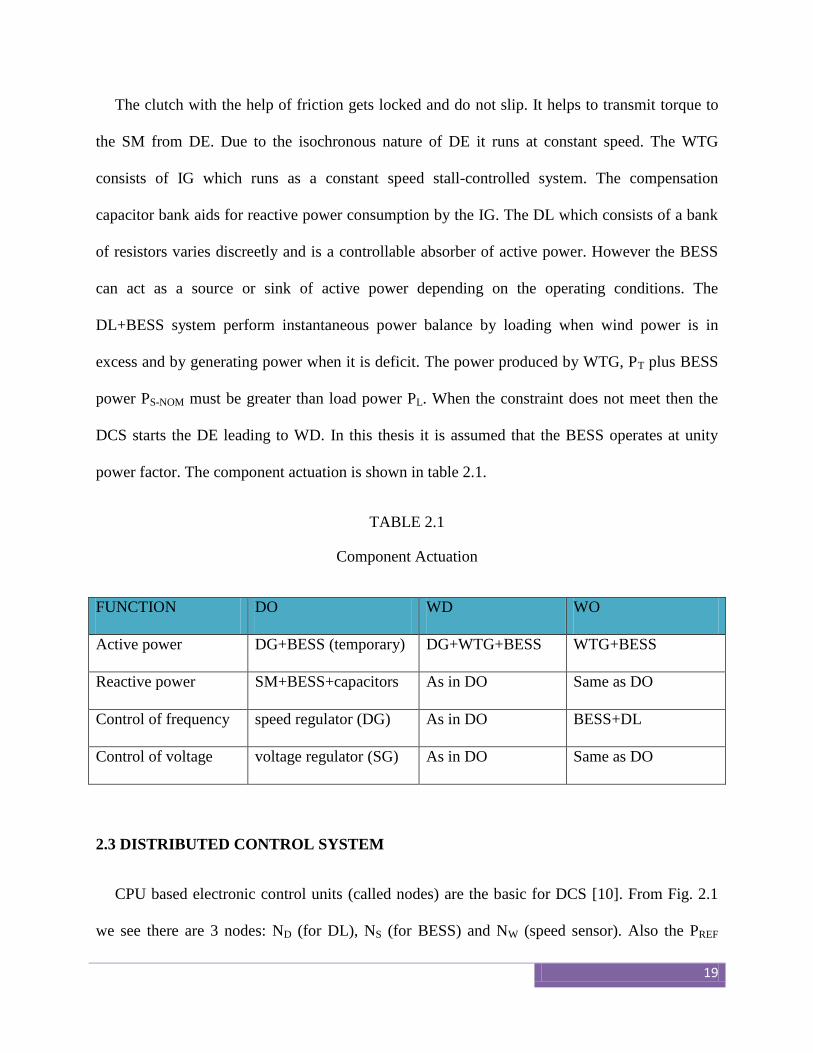
power factor. The component actuation is shown in table 2.1.
TABLE 2.1
Component Actuation
FUNCTION DO WD WO
Active power DG+BESS (temporary) DG+WTG+BESS WTG+BESS
Reactive power SM+BESS+capacitors As in DO Same as DO
Control of frequency speed regulator (DG) As in DO BESS+DL
Control of voltage voltage regulator (SG) As in DO Same as DO
2.3 DISTRIBUTED CONTROL SYSTEM
CPU based electronic control units (called nodes) are the basic for DCS [10]. From Fig. 2.1
we see there are 3 nodes: ND (for DL), NS (for BESS) and NW (speed sensor). Also the PREF
20
message generated decides whether the auxiliary component would absorb power (PREF>0) or
supply power (PREF<0). The droop speed control used is a PD control where the derivative part
aids in increase of speed response while the proportional part loading/generating of power is
done by BESS for above and under frequency respectively. The advantage of using PD controller
is that it is consistent with the isochronous control of DE which is of PID type.
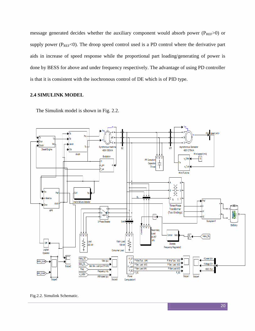
2.4 SIMULINK MODEL
The Simulink model is shown in Fig. 2.2.
Fig.2.2. Simulink Schematic.
21
The nominal power of the WTG is 275KVA. There is no pitch control as it is stall controlled.
The DL comprises of eight three phase resistors which can be turned on or off by GTOs
connected in series [11]. DL’s power consumption can be expressed as 8-bit binary progression.
The subsystem1 connected to the battery is a current controlled inverter (CCI). It is three phase
and bi directional in nature. The PREF signal decides its mode of operation (negative leads to
discharge of battery i.e. battery supplies power and positive signal leads to charging of battery)
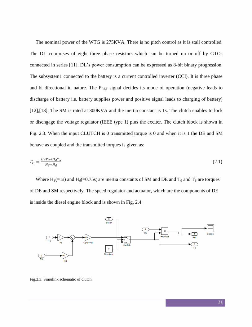
[12],[13]. The SM is rated at 300KVA and the inertia constant is 1s. The clutch enables to lock
or disengage the voltage regulator (IEEE type 1) plus the exciter. The clutch block is shown in
Fig. 2.3. When the input CLUTCH is 0 transmitted torque is 0 and when it is 1 the DE and SM
behave as coupled and the transmitted torques is given as:
(2.1)
Where HS(=1s) and Hd(=0.75s) are inertia constants of SM and DE and Td and TS are torques
of DE and SM respectively. The speed regulator and actuator, which are the components of DE
is inside the diesel engine block and is shown in Fig. 2.4.
Fig.2.3. Simulink schematic of clutch.
22
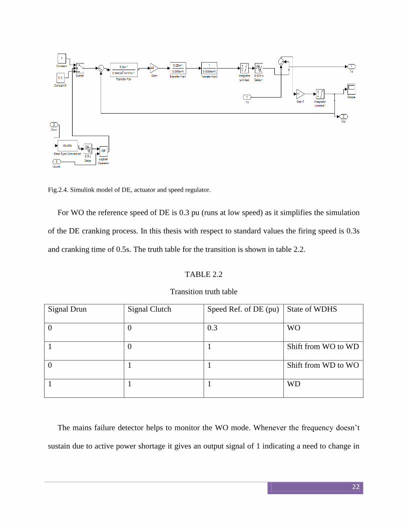
Fig.2.4. Simulink model of DE, actuator and speed regulator.
For WO the reference speed of DE is 0.3 pu (runs at low speed) as it simplifies the simulation
of the DE cranking process. In this thesis with respect to standard values the firing speed is 0.3s
and cranking time of 0.5s. The truth table for the transition is shown in table 2.2.
TABLE 2.2
Transition truth table
Signal Drun Signal Clutch Speed Ref. of DE (pu) State of WDHS
0 0 0.3 WO
1 0 1 Shift from WO to WD
0 1 1 Shift from WD to WO
1 1 1 WD
The mains failure detector helps to monitor the WO mode. Whenever the frequency doesn’t
sustain due to active power shortage it gives an output signal of 1 indicating a need to change in
23
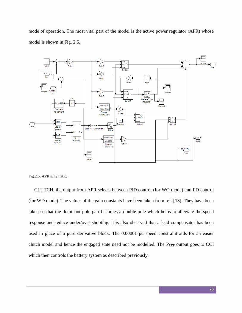
mode of operation. The most vital part of the model is the active power regulator (APR) whose
model is shown in Fig. 2.5.
Fig.2.5. APR schematic.
CLUTCH, the output from APR selects between PID control (for WO mode) and PD control
(for WD mode). The values of the gain constants have been taken from ref. [13]. They have been
taken so that the dominant pole pair becomes a double pole which helps to alleviate the speed
response and reduce under/over shooting. It is also observed that a lead compensator has been
used in place of a pure derivative block. The 0.00001 pu speed constraint aids for an easier
clutch model and hence the engaged state need not be modelled. The PREF output goes to CCI
which then controls the battery system as described previously.
24
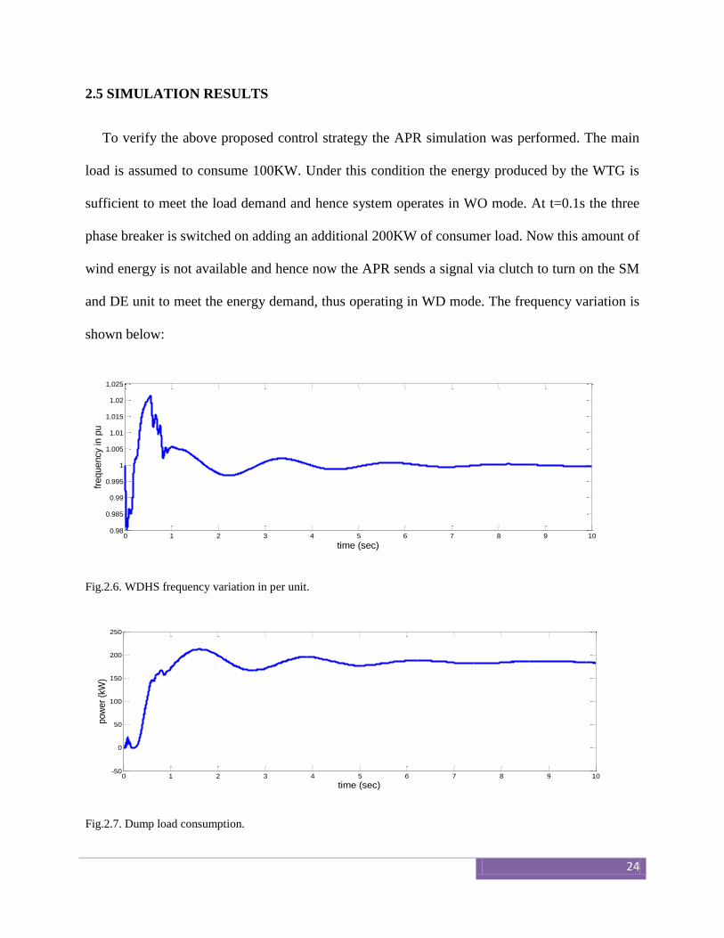
2.5 SIMULATION RESULTS
To verify the above proposed control strategy the APR simulation was performed. The main
load is assumed to consume 100KW. Under this condition the energy produced by the WTG is
sufficient to meet the load demand and hence system operates in WO mode. At t=0.1s the three
phase breaker is switched on adding an additional 200KW of consumer load. Now this amount of
wind energy is not available and hence now the APR sends a signal via clutch to turn on the SM
and DE unit to meet the energy demand, thus operating in WD mode. The frequency variation is
shown below:
Fig.2.6. WDHS frequency variation in per unit.
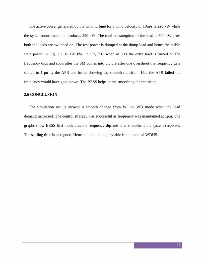
Fig.2.7. Dump load consumption.
0 1 2 3 4 5 6 7 8 9 100.98
0.985
0.99
0.995
1
1.005
1.01
1.015
1.02
1.025
time (sec)
frequency in p
u
0 1 2 3 4 5 6 7 8 9 10-50
0
50
100
150
200
250
time (sec)
pow
er
(kW
)
25
The active power generated by the wind turbine for a wind velocity of 10m/s is 220 kW while
the synchronous machine produces 250 kW. The total consumption of the load is 300 kW after
both the loads are switched on. The rest power is dumped at the dump load and hence the stable
state power in Fig. 2.7. is 170 kW. In Fig. 2.6. when at 0.1s the extra load is turned on the
frequency dips and soon after the SM comes into picture after one overshoot the frequency gets
settled to 1 pu by the APR and hence showing the smooth transition. Had the APR failed the
frequency would have gone down. The BESS helps in the smoothing the transition.
2.6 CONCLUSION
The simulation results showed a smooth change from WO to WD mode when the load
demand increased. The control strategy was successful as frequency was maintained at 1p.u. The
graphs show BESS first moderates the frequency dip and later smoothens the system response.
The settling time is also good. Hence the modelling is viable for a practical WDHS.

26
CHAPTER 3
Dynamic stability performance in WDHS
using IG and PMIG: a comparison
27
3.1 INTRODUCTION
In the previous chapter the simulation was studied using an IG for the WTG. IGs are
beneficial as synchronization is not necessary for varying wind speeds. But the IG has poor
voltage regulation, power factor and efficiency because it requires magnetizing current [14],
[15]. Since PMIG have permanent magnets (mounted on a second rotor) the above shortcomings
become better by the use of them. The efficiency is high over a wide range of slip for PMIG. So
in this chapter we study the dynamic performance for two different loading conditions while the
active and reactive power varies (step change) for both the IG and PMIG case. Many models
have been documented in the literature for modelling of PMIG like d-q reference model [16],
impedance model [17] etc. STATCOMs are proposed to eliminate the mismatch of reactive
power. The STATCOM used in this thesis uses a VSC which internally generates reactive power.
The mathematical model is based on small signal model using state space modelling. The
nomenclatures used in this chapter are:
KE, KF, KA : gain of exciter, stabilizer and voltage regulator.
∆Efd, ∆Eq : small deviations in voltage of exciter, and internal armature emf of SG.
∆Eq’ : small deviations in internal armature emf of SG in transient condition.
KP,KI : PI gains of STATCOM and converter controllers.
QWG, PWG : reactive and active power generated by wind generators.
QDG, PDG : reactive and active power consumed by DGs.
Qcom : reactive power supplied by STATCOM.
∆PIW : small change in input power of wind.
28
∆α : phase angle deviation of STATCOM.
Tα,Td, T1 : transport lag, average dead time of zero crossing and main time constant.
Req,Xeq,Xm : equivalent resistance, reactance and magnetizing reactance of PMIG/IG.
s : slip
Xd,Xd’ : direct axis reactance of SG.
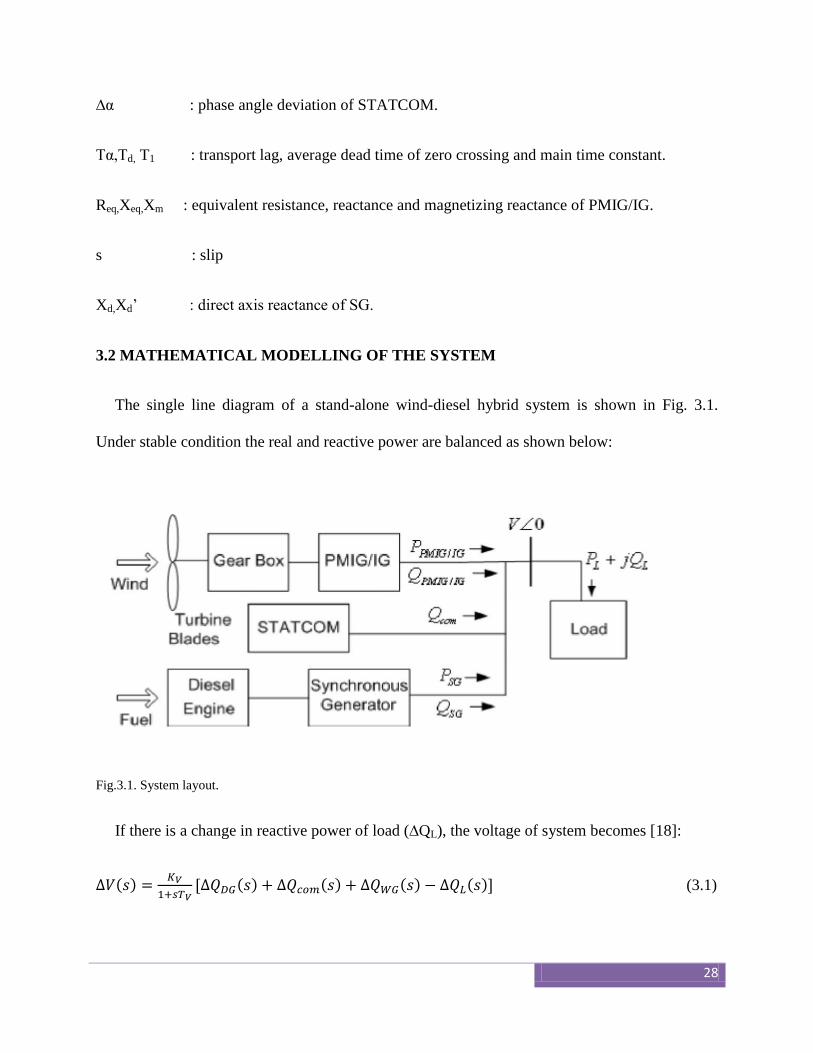
3.2 MATHEMATICAL MODELLING OF THE SYSTEM
The single line diagram of a stand-alone wind-diesel hybrid system is shown in Fig. 3.1.
Under stable condition the real and reactive power are balanced as shown below:
Fig.3.1. System layout.
If there is a change in reactive power of load (∆QL), the voltage of system becomes [18]:
( )
( ) ( ) ( ) ( ) (3.1)
29
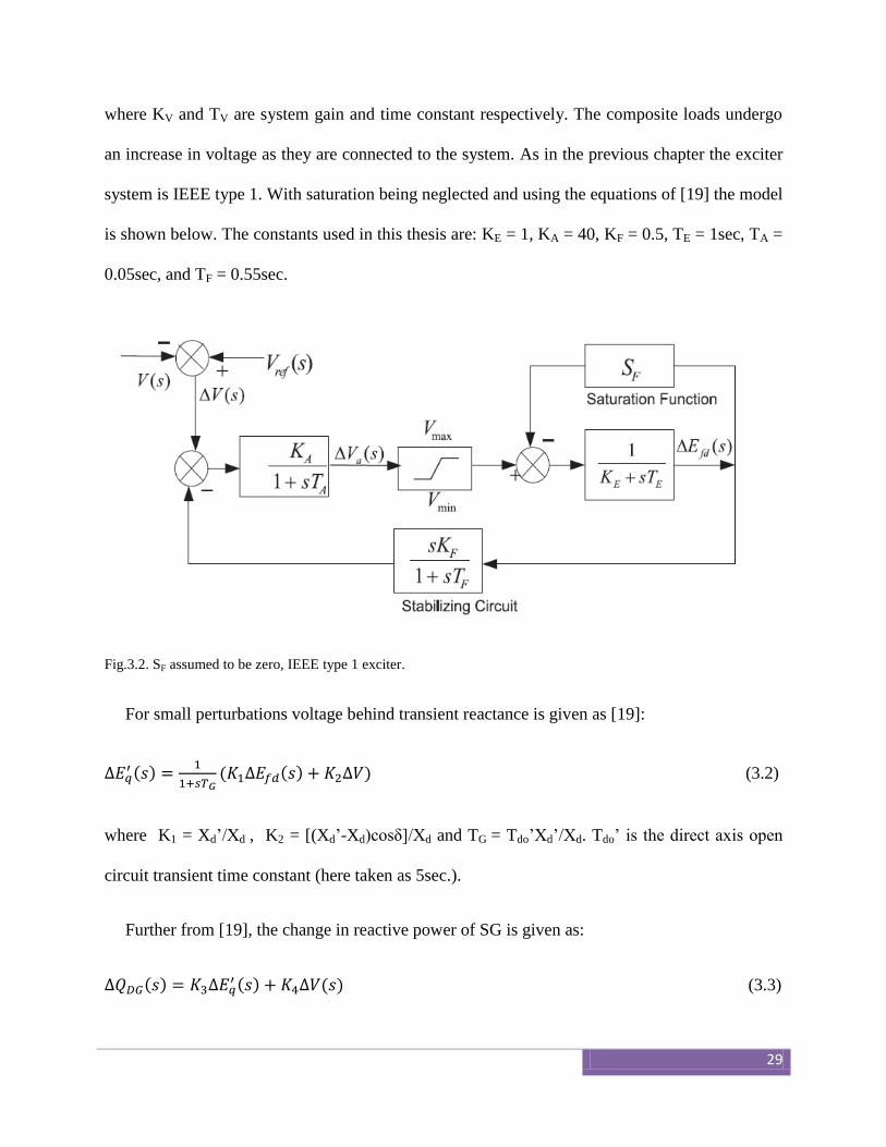
where KV and TV are system gain and time constant respectively. The composite loads undergo
an increase in voltage as they are connected to the system. As in the previous chapter the exciter
system is IEEE type 1. With saturation being neglected and using the equations of [19] the model
is shown below. The constants used in this thesis are: KE = 1, KA = 40, KF = 0.5, TE = 1sec, TA =
0.05sec, and TF = 0.55sec.
Fig.3.2. SF assumed to be zero, IEEE type 1 exciter.
For small perturbations voltage behind transient reactance is given as [19]:
( )
( ( ) ) (3.2)
where K1 = Xd’/Xd , K2 = [(Xd’-Xd)cosδ]/Xd and TG = Tdo’Xd’/Xd. Tdo’ is the direct axis open
circuit transient time constant (here taken as 5sec.).
Further from [19], the change in reactive power of SG is given as:
( ) ( ) ( ) (3.3)
30
Where K3 = Vcosδ/Xd’ and K4 = [Eq’cosδ-2V]/Xd’.
The approximate circuit of PMIG is similar to that of IG except the addition of an extra
magnetizing reactance in parallel with core loss reactance. From [20], the equations for reactive
power consumption of PMIG can be given as:
( ) (3.4)
where
{
} (3.5)
(3.6)
( ) (3.7)
( )
(3.8)
(3.9)
(3.10)
However if the input wind power also changes the above equations modifies into the
following:
( ) ( ) (3.11)
Where
{ ( ) } (3.12)
31
[
{( )
( )
}] (3.13)
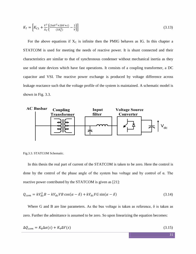
For the above equations if XC is infinite then the PMIG behaves as IG. In this chapter a
STATCOM is used for meeting the needs of reactive power. It is shunt connected and their
characteristics are similar to that of synchronous condenser without mechanical inertia as they
use solid state devices which have fast operations. It consists of a coupling transformer, a DC
capacitor and VSI. The reactive power exchange is produced by voltage difference across
leakage reactance such that the voltage profile of the system is maintained. A schematic model is
shown in Fig. 3.3.
Fig.3.3. STATCOM Schematic.
In this thesis the real part of current of the STATCOM is taken to be zero. Here the control is
done by the control of the phase angle of the system bus voltage and by control of α. The
reactive power contributed by the STATCOM is given as [21]:
( ) ( ) (3.14)
Where G and B are line parameters. As the bus voltage is taken as reference, δ is taken as
zero. Further the admittance is assumed to be zero. So upon linearizing the equation becomes:
( ) ( ) (3.15)
32
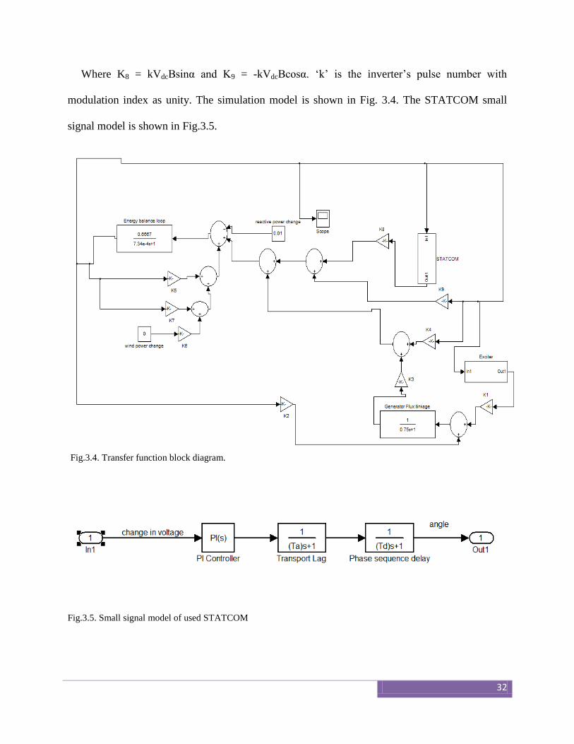
Where K8 = kVdcBsinα and K9 = -kVdcBcosα. ‘k’ is the inverter’s pulse number with
modulation index as unity. The simulation model is shown in Fig. 3.4. The STATCOM small
signal model is shown in Fig.3.5.
Fig.3.4. Transfer function block diagram.
Fig.3.5. Small signal model of used STATCOM
33
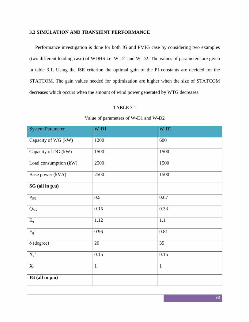
3.3 SIMULATION AND TRANSIENT PERFORMANCE
Performance investigation is done for both IG and PMIG case by considering two examples
(two different loading case) of WDHS i.e. W-D1 and W-D2. The values of parameters are given
in table 3.1. Using the ISE criterion the optimal gain of the PI constants are decided for the
STATCOM. The gain values needed for optimization are higher when the size of STATCOM
decreases which occurs when the amount of wind power generated by WTG decreases.
TABLE 3.1
Value of parameters of W-D1 and W-D2
System Parameter W-D1 W-D2
Capacity of WG (kW) 1200 600
Capacity of DG (kW) 1500 1500
Load consumption (kW) 2500 1500
Base power (kVA) 2500 1500
SG (all in p.u)
PSG 0.5 0.67
QSG 0.15 0.33
Eq 1.12 1.1
Eq’ 0.96 0.81
δ (degree) 20 35
Xd’ 0.15 0.15
Xd 1 1
IG (all in p.u)
34
PIG 0.5 0.33
QIG 0.21 0.16
r1 = r2’ 0.15 0.25
x1 = x2’ 0.5 0.75
s (%) -3 -3
PMIG (all in p.u)
PIG 0.5 0.33
QIG 0.21 0.16
r1 = r2’ 0.15 0.25
x1 = x2’ 0.5 0.75
s (%) -3 -3
The loading of diesel generator is 66.67% under regular operating conditions whereas the
efficiency of the IG and PMIG is 90%. The STATCOM constants are: main time constant is
20ms, delay time constant (Td) is 1.67ms and transport lag time constant (Tα) is 0.25ms. The load
is assumed to operate at 0.8 power factor. Hence using the above table the constants K1-K9 can
be calculated. KV is taken as 0.667 while TV = 7.34E-04 sec.
To observe the transient performance the change in system voltage and the reactive power of
the STATCOM, diesel engine and that of the WTG (either IG or PMIG) are observed. The same
is done by first observing a change with 0.01 (p.u) step change in reactive power of load and then
same change in both input wind power and load reactive power. Fig. 3.6 shows the graphs of IG
for both the examples and perturbation of load power while Fig. 3.7 shows that of both load and
wind power. Similarly Fig. 3.8 and Fig. 3.9 show the results of PMIG.
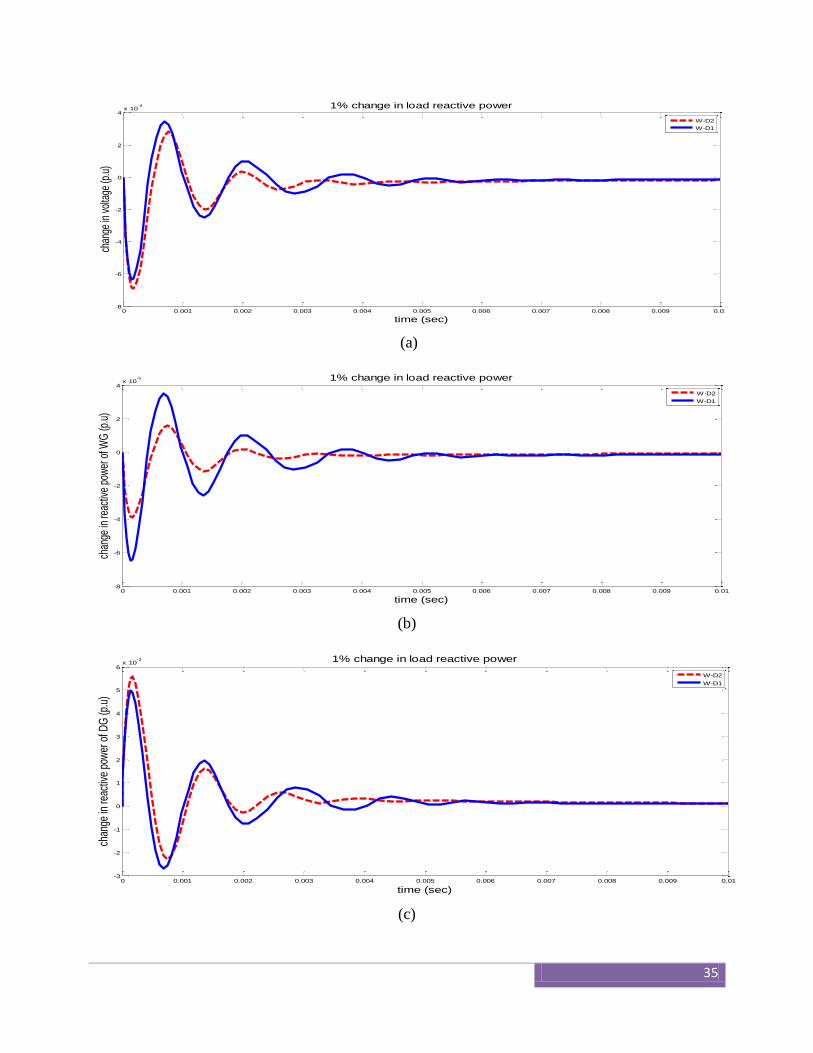
35
(a)
(b)
(c)
0 0.001 0.002 0.003 0.004 0.005 0.006 0.007 0.008 0.009 0.01-8
-6
-4
-2
0
2
4x 10
-4 1% change in load reactive power
time (sec)
chan
ge in
vol
tage
(p.u
)
W-D2
W-D1
0 0.001 0.002 0.003 0.004 0.005 0.006 0.007 0.008 0.009 0.01-8
-6
-4
-2
0
2
4x 10
-5
time (sec)
chan
ge in
reac
tive
pow
er o
f WG
(p.u
)
1% change in load reactive power
W-D2
W-D1
0 0.001 0.002 0.003 0.004 0.005 0.006 0.007 0.008 0.009 0.01-3
-2
-1
0
1
2
3
4
5
6x 10
-3
time (sec)
chan
ge in
reac
tive
pow
er o
f DG
(p.u
)
1% change in load reactive power
W-D2
W-D1
36
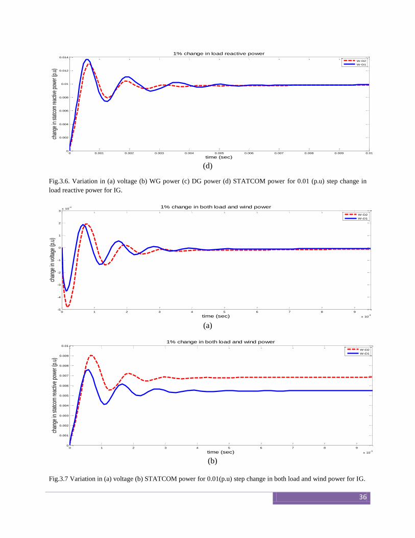
(d)
Fig.3.6. Variation in (a) voltage (b) WG power (c) DG power (d) STATCOM power for 0.01 (p.u) step change in
load reactive power for IG.
(a)
(b)
Fig.3.7 Variation in (a) voltage (b) STATCOM power for 0.01(p.u) step change in both load and wind power for IG.
0 0.001 0.002 0.003 0.004 0.005 0.006 0.007 0.008 0.009 0.010
0.002
0.004
0.006
0.008
0.01
0.012
0.014
time (sec)
chan
ge in
sta
tcom
reac
tive
pow
er (p
.u)
1% change in load reactive power
W-D2
W-D1
0 1 2 3 4 5 6 7 8 9
x 10-3
-5
-4
-3
-2
-1
0
1
2
3x 10
-4
time (sec)
chan
ge in
vol
tage
(p.u
)
1% change in both load and wind power
W-D2
W-D1
0 1 2 3 4 5 6 7 8 9
x 10-3
0
0.001
0.002
0.003
0.004
0.005
0.006
0.007
0.008
0.009
0.01
time (sec)
chan
ge in
sta
tcom
reac
tive
pow
er (p
.u)
1% change in both load and wind power
W-D2
W-D1
37
(a)
(b)
0 0.001 0.002 0.003 0.004 0.005 0.006 0.007 0.008 0.009 0.01-8
-6
-4
-2
0
2
4x 10
-4
time (sec)
chan
ge in
vol
tage
(p.
u)1% change in load reactive power
W-D1
W-D2
0 0.001 0.002 0.003 0.004 0.005 0.006 0.007 0.008 0.009 0.01-2
-1
0
1
2
3
4
5
6x 10
-4
time (sec)
change in
react
ive p
ow
er
of W
G (
p.u
)
1% change in load reactive power
W-D2
W-D1
38
(c)
(d)
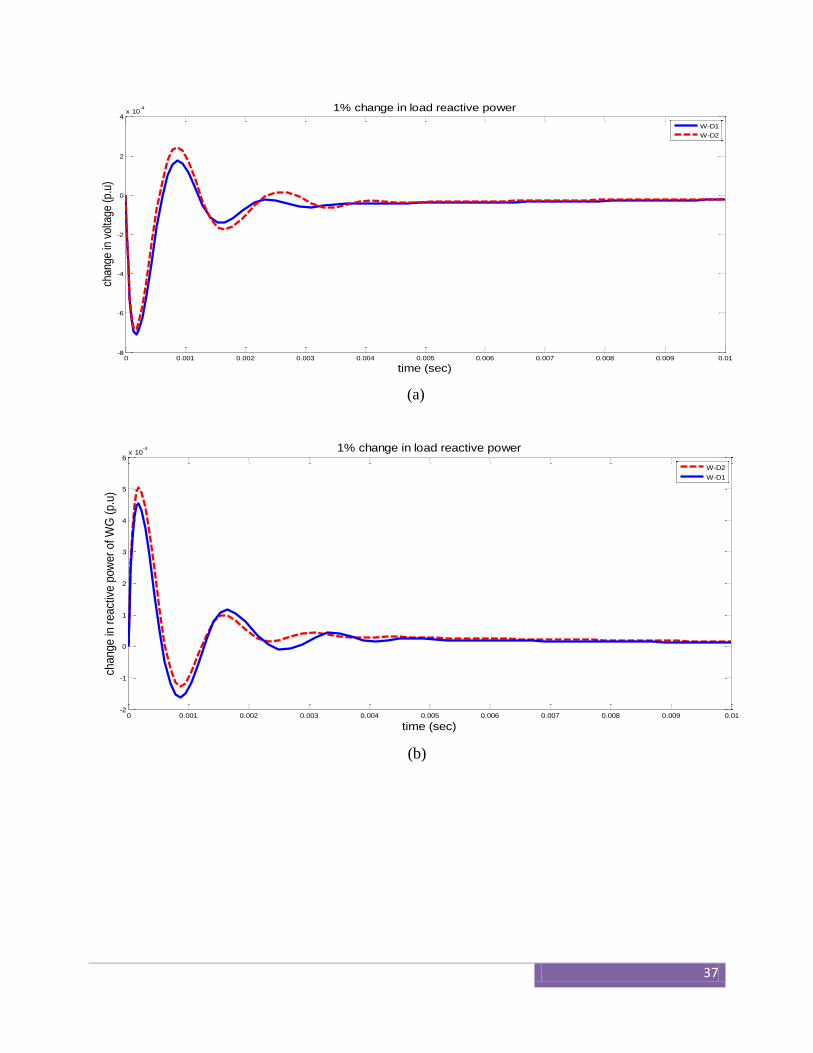
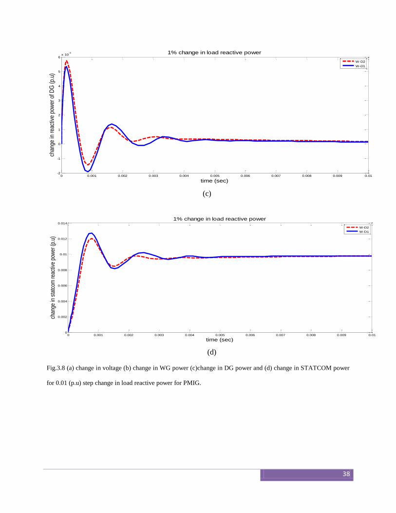
Fig.3.8 (a) change in voltage (b) change in WG power (c)change in DG power and (d) change in STATCOM power
for 0.01 (p.u) step change in load reactive power for PMIG.
0 0.001 0.002 0.003 0.004 0.005 0.006 0.007 0.008 0.009 0.01-2
-1
0
1
2
3
4
5
6x 10
-3
time (sec)
chan
ge in
rea
ctiv
e po
wer
of D
G (
p.u)
1% change in load reactive power
W-D2
W-D1
0 0.001 0.002 0.003 0.004 0.005 0.006 0.007 0.008 0.009 0.010
0.002
0.004
0.006
0.008
0.01
0.012
0.014
time (sec)
chan
ge in
sta
tcom
reac
tive
pow
er (p
.u)
1% change in load reactive power
W-D2
W-D1
39
(a)
(b)
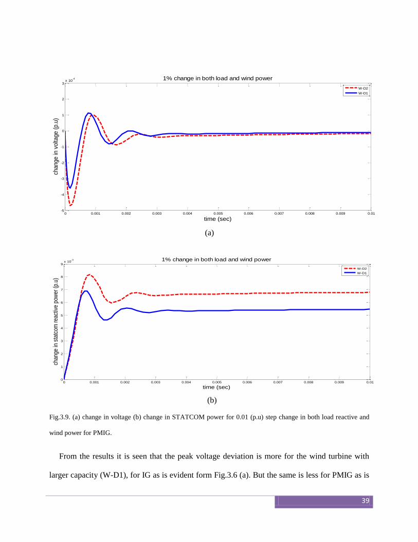
Fig.3.9. (a) change in voltage (b) change in STATCOM power for 0.01 (p.u) step change in both load reactive and
wind power for PMIG.
From the results it is seen that the peak voltage deviation is more for the wind turbine with
larger capacity (W-D1), for IG as is evident form Fig.3.6 (a). But the same is less for PMIG as is
0 0.001 0.002 0.003 0.004 0.005 0.006 0.007 0.008 0.009 0.01-5
-4
-3
-2
-1
0
1
2
3x 10
-4
time (sec)
change in
volta
ge (
p.u
)
1% change in both load and wind power
W-D2
W-D1
0 0.001 0.002 0.003 0.004 0.005 0.006 0.007 0.008 0.009 0.010
1
2
3
4
5
6
7
8
9x 10
-3
time (sec)
chan
ge in
sta
tcom
rea
ctiv
e po
wer
(p.
u)
1% change in both load and wind power
W-D2
W-D1
40
evident from Fig.3.8 (a). It is also observed that the STATCOM immediately supplies the extra
reactive power of 0.01 p.u as is evident from Fig. 3.6 (d) and Fig. 3.8 (d). After stabilization it is
the STATCOM that caters the deficit reactive power demand. The STATCOM has a very fast
response as seen from the graphs, where steady state is achieved within 0.01sec. As seen from
Fig. 3.7 and Fig. 3.9 the reactive power demand increases when there is step increase in both
load and wind power. The automatic voltage regulators used with the diesel engines are not able
to maintain the voltage as desired and hence the above setup with STATCOM helps to achieve
the system constraint.
3.4 CONCLUSION
Two examples of WDHS were considered for study with different wind generation capacity
and the response was compared with IG and PMIG. It is shown how the STATCOM serves the
purpose for fast action to maintain the stability. PMIG have definitely the edge over IG as use for
WTG. The size of STATCOM also reduces when PMIG is used; however they have comparable
fluctuations when the WDHS system uses IG. The agreement with the simulation results to a
prodigious extent that use of PMIG can definitely be beneficial.

41
CHAPTER 4
CONCLUSION AND FUTURE WORK

42
4.1 CONCLUSIONS
Here, in the thesis a stand-alone WDHS was successfully modelled which have become a
crucial part for communities that are far away from utility grid.
A control strategy was developed for the WDHS such that there was a smooth transition
from WO mode to WD mode when there was power shortage.
An IG was used to model the above design with no pitch control. An assumption for sake
of simplicity was done while designing the clutch system. The DE instead of being
completely stopped was allowed to run at a slow speed.
A BESS system was also introduced in the WDHS such that the transition was smooth.
After considering the previous system next a mathematical model was developed for
investigating the performance of IG and PMIG under dynamic conditions.
Simulation results were then obtained to show that PMIG can definitely be a better
bargain as compared to IG.
4.2 FUTURE WORK
In chapter 2 we used a PD controller. Better results can be expected by use of fuzzy logic
for control strategy.
Apart from PMIG performance for permanent magnet synchronous generator (PMSG)
can also be studied to get an overall idea about which generator would serve the purpose
for energy production to the best along with use of artificial neural nets.
43
References
[01] F.Blaabjerg, R. Teodorescu, M. Liserre, A.V.Timbus, , "Overview of Control and
Grid Synchronization for Distributed Power Generation Systems," IEEE Transactions
on Industrial Electronics, , vol.53, no.5, pp.1398-1409, Oct. 2006.
[02] Wind-Diesel Systems Architecture Guidebook. American Wind Energy Association;
1991.
[03] T. K. Saha and D. Kastha, “Design optimization and dynamic performance analysis of a
standalone hybrid wind diesel electrical power generation system,” IEEE Trans. Energy
Convers., vol. 25, no. 4, pp. 1209–1217, Dec. 2010.
[04] S. M. B. Wilmshurst, “Control strategies for wind turbines,” Wind Eng., vol. 12, pp.
236–249, Jul. 1988.
[05] Z. Chen and Y. Hu, “A hybrid generation system using variable speed wind turbines
and diesel units,” in Proc. IEEE Ind. Electron. Soc. Annu. Meeting Conf., Nov. 2003,
pp. 2729–2734.
[06] Muljadi E, McKenna HE. Power quality issues in a hybrid power system. IEEE Trans
Ind Appl 2002;38(3):803–9.
[07] Sedaghat B, Jalilvand A, Noroozian R. Design of a multilevel control strategy for
integration of stand-alone wind/diesel system. Int J Electr Power Energy Syst
2012;35(1):123–37.
[08] Elkhatib Kamal, Magdy Koutb, Abdul Azim Sobaih, Belal Abozalam. An intelligent
maximum power extraction algorithm for hybrid wind-dieselstorage system. Int J Electr
Power Energy Syst 2010;32(3):170–7.
44
[09] Hunter R, Infield D, Kessler S, de Bonte J, Toftevaag T, Sherwin B, et al. Designing a
system. In: Hunter R, Eliot G, editors. Wind–diesel systems: a guide to the technology
and its implementations. UK: Cambridge University Press; 1994 [chapter 4].
[10] Lawrenz W. CAN system engineering. Berlin: Springer; 1997.
[11] Gagnon R, Saulnier B, Sybille G, Giroux P. Modeling of a generic high-penetration no-
storage wind–diesel system using matlab/power system blockset. 2002 Global
windpower conference; April 2002. Paris, France.
[12] Liaw CM, Chiang SJ, Huang SC. A three-phase multi-functional battery energy storage
system. In: International conference on industrial electronics, control and
instrumentation, 1994. IECON ‘94, 20th, vol. 1, 5–9 September 1994; p. 458–63.
[13] Sebastia´n R, Quesada J. Distributed control system for frequency control in an isolated
wind system. Renew Energy 2006;31:285–305 [Elsewier].
[14] T. Zhou and B. Francois, “Energy management and power control of a hybrid active
wind generator for distributed power generation and grid integration,” IEEE Trans. Ind.
Electron., vol. 58, no. 1, pp. 95–104, Jan. 2011.
[15] T. Fukami, K. Nakagawa, Y. Kanamaru, and T. Miyamoto, “A technique for the steady-
state analysis of a grid-connected permanent-magnet induction generator,” IEEE Trans.
Energy Convers., vol. 19, no. 2, pp. 318–324, Jun. 2004.
[16] J. F. H. Douglas, “Characteristics of induction motors with permanent magnet
excitation,” AIEE Trans. Power App. Syst., vol. 78, no. 3, pp. 221–225, Apr. 1959.
[17] B. Ackermann, “Single phase induction motor with permanent-magnet excitation,”
IEEE Trans. Magn., vol. 36, no. 5, pp. 3530–3532, Sep. 2000.
45
[18] Boldea I. Variable speed generators (the electric generators handbook). CRC Press;
2012.
[19] R. C. Bansal, “Automatic reactive power control of isolated wind–diesel hybrid power
systems,” IEEE Trans. Ind. Electron., vol. 53, no. 4, pp. 1116–1126, Jun. 2006.
[20] J. H. J. Potgieter, A. N. Lombard, R. J. Wang, and M. J. Kamper, Evaluation of
Permanent-Magnet Excited Induction Generator for Renewable Energy Applications.
[21] B. Kouadri and Y. Tahir, “Power flow and transient stability modeling of a 12-pulse
statcom,” J. Cybern. Inform., vol. 7, pp. 9–25, 2008.


![UNIVERSITY OF PUNE [4364]-90 B. E. (Production)unipune.ac.in/university_files/pdf/old_papers/april2013/... · UNIVERSITY OF PUNE [4364]-90. B. E. ... slide rule, Mollier charts,](https://img.pdfslide.net/doc/110x75/5acb51637f8b9a73128b8251/university-of-pune-4364-90-b-e-production-of-pune-4364-90-b-e-slide.jpg)