Embed Size (px)
Citation preview

E-bike DIY USER MANUAL
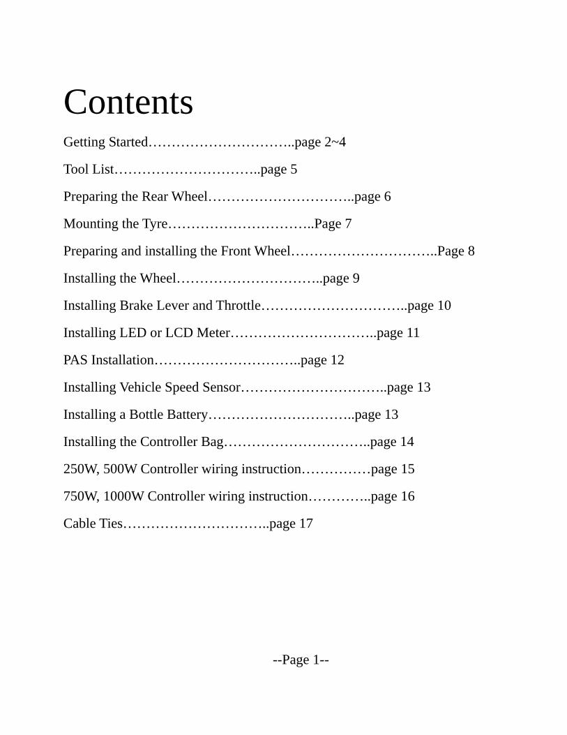
Contents Getting Started…………………………..page 2~4
Tool List…………………………..page 5
Preparing the Rear Wheel…………………………..page 6
Mounting the Tyre…………………………..Page 7
Preparing and installing the Front Wheel…………………………..Page 8
Installing the Wheel…………………………..page 9
Installing Brake Lever and Throttle…………………………..page 10
Installing LED or LCD Meter…………………………..page 11
PAS Installation…………………………..page 12
Installing Vehicle Speed Sensor…………………………..page 13
Installing a Bottle Battery…………………………..page 13
Installing the Controller Bag…………………………..page 14
250W, 500W Controller wiring instruction……………page 15
750W, 1000W Controller wiring instruction…………..page 16
Cable Ties…………………………..page 17
--Page 1--

The simplest E-bike conversion kits
--Page 2--
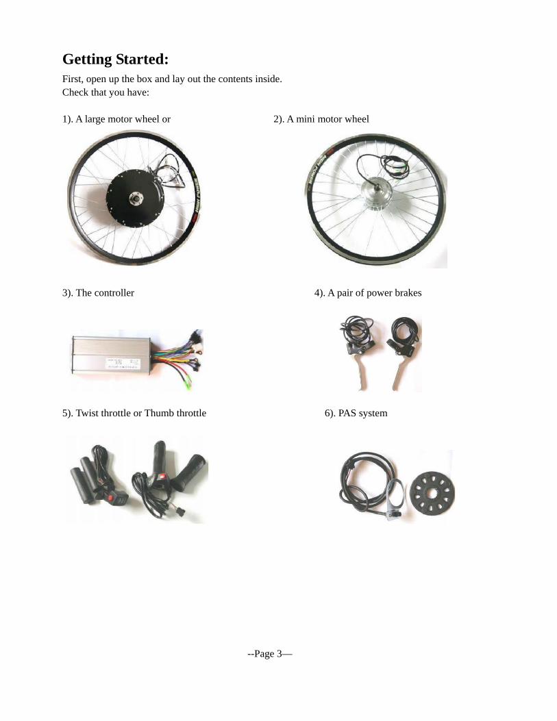
Getting Started: First, open up the box and lay out the contents inside. Check that you have: 1). A large motor wheel or 2). A mini motor wheel
3). The controller 4). A pair of power brakes
5). Twist throttle or Thumb throttle 6). PAS system
--Page 3—

Optional Items: 1). Lithium Battery 2). Controller’s Bag
3). LED Meter or 4). Multifunction LCD meter
Different types of lithium batteries
--Page 4—
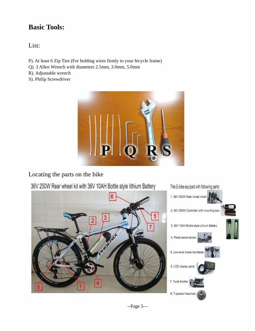
Basic Tools:
List: P). At least 6 Zip Ties (For holding wires firmly to your bicycle frame) Q). 3 Allen Wrench with diameters 2.5mm, 3.0mm, 5.0mm R). Adjustable wrench S). Philip Screwdriver
Locating the parts on the bike
--Page 5—
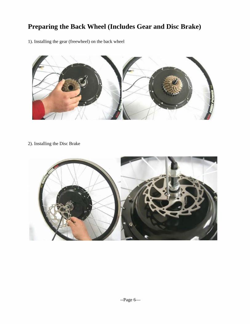
Preparing the Back Wheel (Includes Gear and Disc Brake) 1). Installing the gear (freewheel) on the back wheel
2). Installing the Disc Brake
--Page 6—
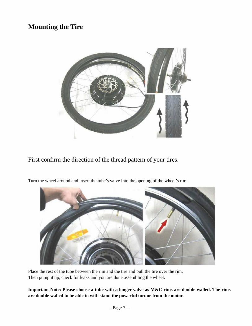
Mounting the Tire
First confirm the direction of the thread pattern of your tires.
Turn the wheel around and insert the tube’s valve into the opening of the wheel’s rim.
Place the rest of the tube between the rim and the tire and pull the tire over the rim. Then pump it up, check for leaks and you are done assembling the wheel. Important Note: Please choose a tube with a longer valve as M&C rims are double walled. The rims are double walled to be able to with stand the powerful torque from the motor. --Page 7—
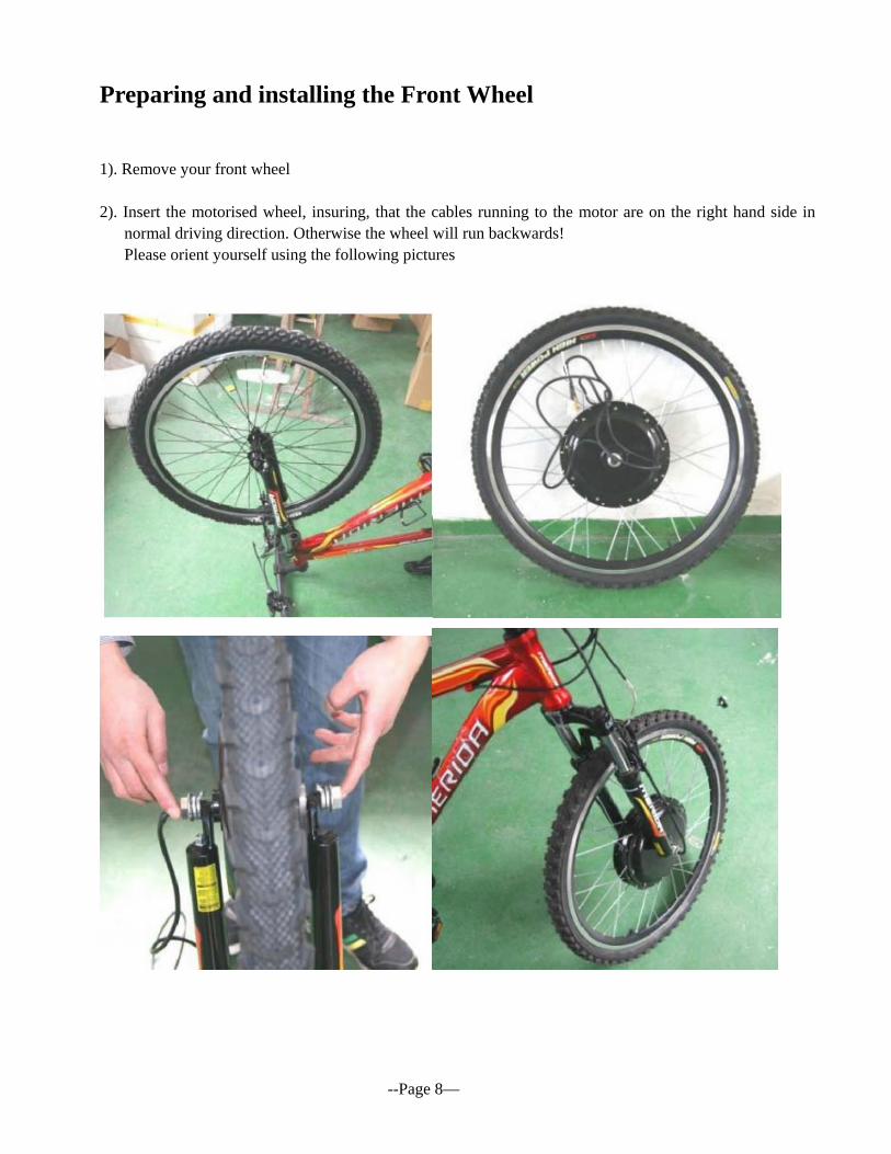
Preparing and installing the Front Wheel
1). Remove your front wheel 2). Insert the motorised wheel, insuring, that the cables running to the motor are on the right hand side in
normal driving direction. Otherwise the wheel will run backwards! Please orient yourself using the following pictures
--Page 8—
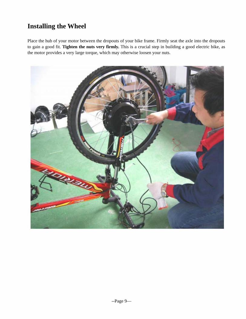
Installing the Wheel Place the hub of your motor between the dropouts of your bike frame. Firmly seat the axle into the dropouts to gain a good fit. Tighten the nuts very firmly. This is a crucial step in building a good electric bike, as the motor provides a very large torque, which may otherwise loosen your nuts.
--Page 9—
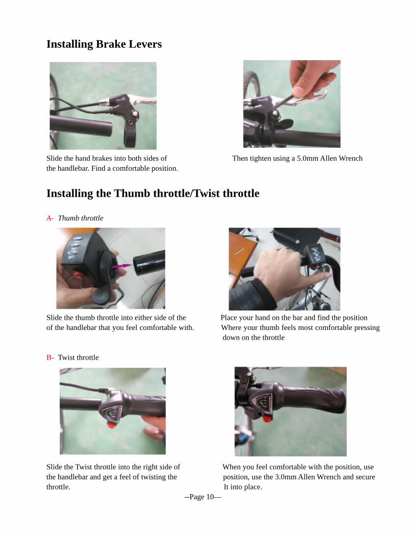
Installing Brake Levers
Slide the hand brakes into both sides of Then tighten using a 5.0mm Allen Wrench the handlebar. Find a comfortable position.
Installing the Thumb throttle/Twist throttle A- Thumb throttle
Slide the thumb throttle into either side of the Place your hand on the bar and find the position of the handlebar that you feel comfortable with. Where your thumb feels most comfortable pressing
down on the throttle B- Twist throttle
Slide the Twist throttle into the right side of When you feel comfortable with the position, use the handlebar and get a feel of twisting the position, use the 3.0mm Allen Wrench and secure throttle. It into place. --Page 10—
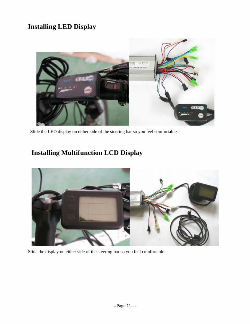
Installing LED Display
Slide the LED display on either side of the steering bar so you feel comfortable.
Installing Multifunction LCD Display
Slide the display on either side of the steering bar so you feel comfortable --Page 11—
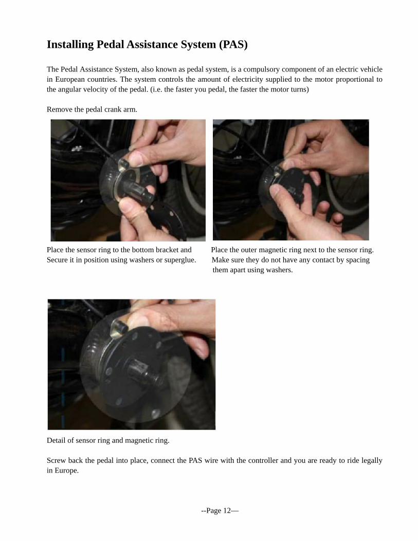
Installing Pedal Assistance System (PAS) The Pedal Assistance System, also known as pedal system, is a compulsory component of an electric vehicle in European countries. The system controls the amount of electricity supplied to the motor proportional to the angular velocity of the pedal. (i.e. the faster you pedal, the faster the motor turns) Remove the pedal crank arm.
Place the sensor ring to the bottom bracket and Place the outer magnetic ring next to the sensor ring. Secure it in position using washers or superglue. Make sure they do not have any contact by spacing them apart using washers.
Detail of sensor ring and magnetic ring. Screw back the pedal into place, connect the PAS wire with the controller and you are ready to ride legally in Europe. --Page 12—
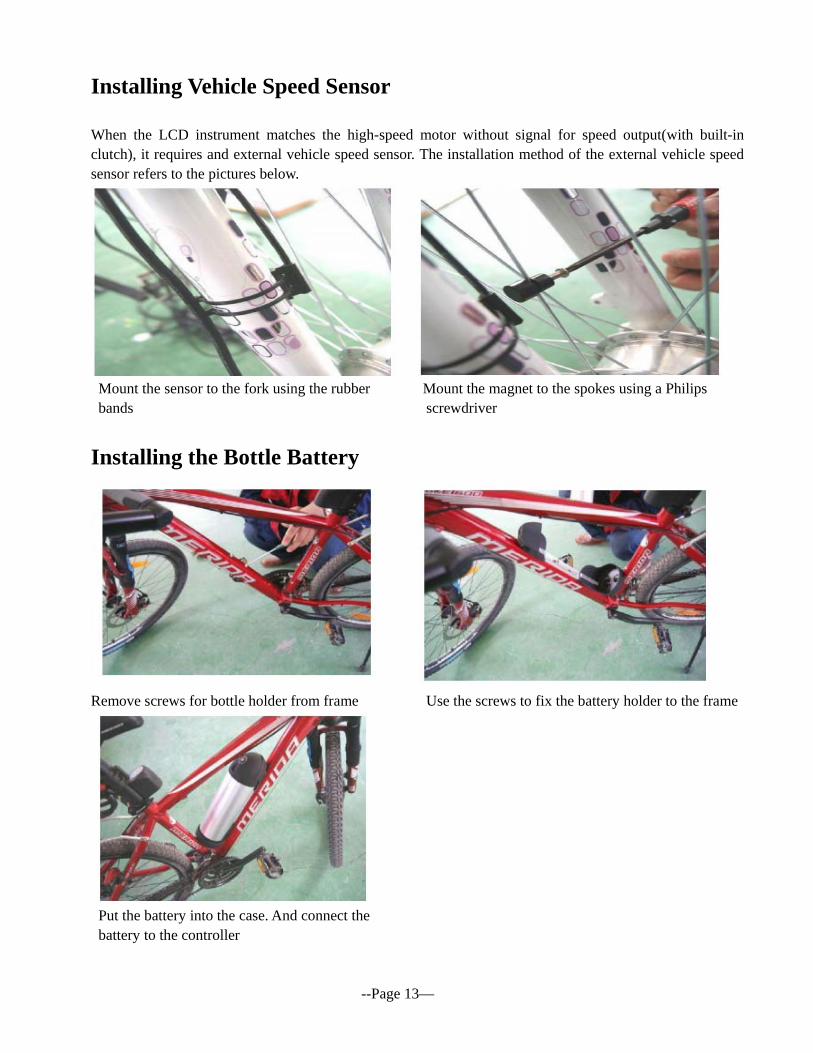
Installing Vehicle Speed Sensor When the LCD instrument matches the high-speed motor without signal for speed output(with built-in clutch), it requires and external vehicle speed sensor. The installation method of the external vehicle speed sensor refers to the pictures below.
Mount the sensor to the fork using the rubber Mount the magnet to the spokes using a Philips
bands screwdriver
Installing the Bottle Battery
Remove screws for bottle holder from frame Use the screws to fix the battery holder to the frame
Put the battery into the case. And connect the battery to the controller
--Page 13—
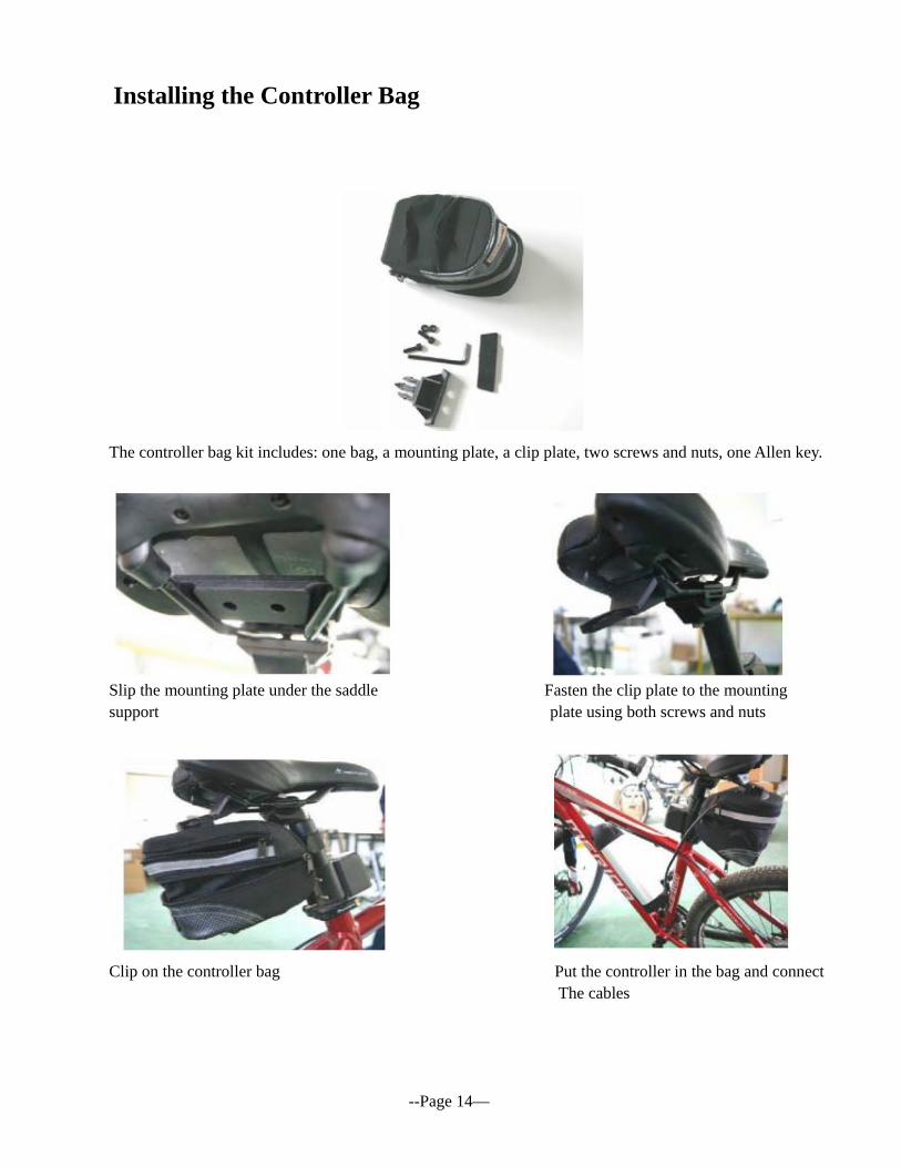
Installing the Controller Bag
The controller bag kit includes: one bag, a mounting plate, a clip plate, two screws and nuts, one Allen key.
Slip the mounting plate under the saddle Fasten the clip plate to the mounting support plate using both screws and nuts
Clip on the controller bag Put the controller in the bag and connect The cables
--Page 14—
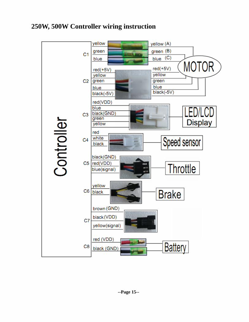
250W, 500W Controller wiring instruction
--Page 15--
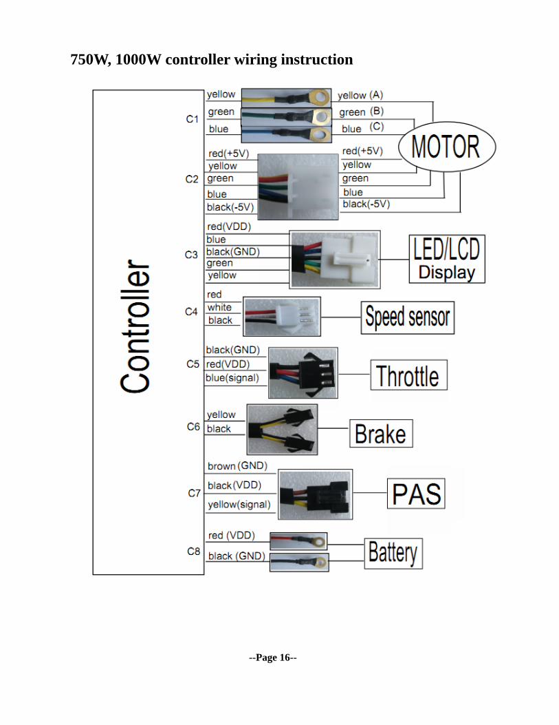
750W, 1000W controller wiring instruction
--Page 16--
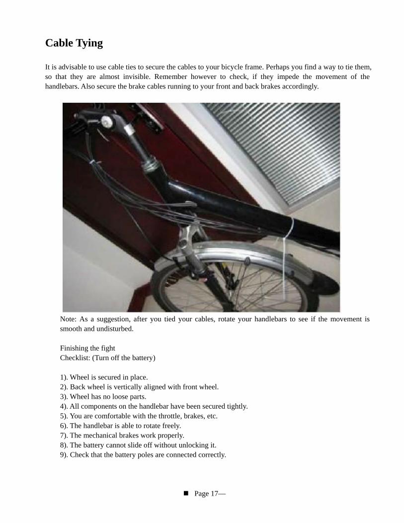
Cable Tying
It is advisable to use cable ties to secure the cables to your bicycle frame. Perhaps you find a way to tie them, so that they are almost invisible. Remember however to check, if they impede the movement of the handlebars. Also secure the brake cables running to your front and back brakes accordingly.
Note: As a suggestion, after you tied your cables, rotate your handlebars to see if the movement is smooth and undisturbed. Finishing the fight Checklist: (Turn off the battery) 1). Wheel is secured in place. 2). Back wheel is vertically aligned with front wheel. 3). Wheel has no loose parts. 4). All components on the handlebar have been secured tightly. 5). You are comfortable with the throttle, brakes, etc. 6). The handlebar is able to rotate freely. 7). The mechanical brakes work properly. 8). The battery cannot slide off without unlocking it. 9). Check that the battery poles are connected correctly.
Page 17—

Motion Dynamics Australia Pty Ltd Website: www.motiondynamics.com.au Add: 3 Rosehill Street, Parramatta, NSW 2150 Tel: +61 2 96879187 Fax: +61 2 80048232