Embed Size (px)
Citation preview

CONTENTS
INTRODUCTION
Company Profile
QUALITY CERTIFICATE
EN ISO 9001: 2000.
NEXT - Steel Enclosure Range
Product specification.
Product technical parameters.
General arrangement drawing.
Ex-Cell - Steel Enclosure Range
Product specification.
Product technical parameters.
General arrangement drawing.
STB - Steel Enclosure Range
Product specification.
Product technical parameters.
General arrangement drawing.
HVB - Steel Enclosure Range
Product specification.
Product technical parameters.
General arrangement drawing.
Kestrel – GRP Enclosure Range
Product specification.
Product technical parameters.
General arrangement drawing.
Enclosure Product Range Size Chart
Customised Enclosure Services
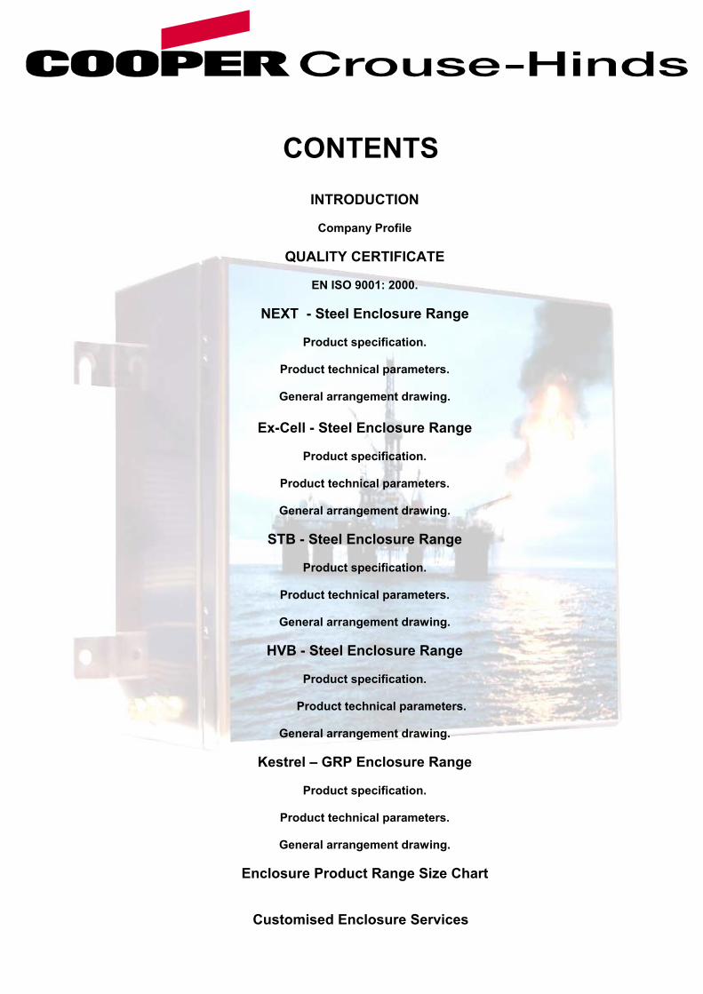
Cooper Crouse- Hinds UK Ltd. is an EN ISO 9001: 2000 registered company manufacturing a range of highquality and robust junction boxes, enclosures and custom electrical assemblies. These have been designed andengineered to meet the requirements of both the most demanding hazardous area, marine and heavy industrialenvironmental applications. With over 30 years of experience in the design, engineering and manufacture of enclosures and custom electricalassemblies, Cooper Crouse-Hinds provides proven, tried and tested solutions using quality materials andprocesses to provide products to endure the toughest environmental conditions for project and installationrequirements. Our core manufacturing expertise is in the manufacture of metallic fabricated enclosures in both steel and variousgrades of stainless steel. These enclosures are available in options of different material finishes including electro-polished, powder coated or natural finish, depending on the material and application. The enclosure product lines are designed and ATEX certified for hazardous areas, UL certified for heavy industrialapplications and are used predominantly in the very demanding petro-chemical, pharmaceutical, food process andutilities market sectors. As a result of this our enclosure have the inherent benefits of a high degree of ingress protection (IP) toenvironmental characteristics such as ingress of water and dust. The ingress protection (IP) of all of our productline is IP66 (water & dust), additionally our enclosure product lines have an impact resistance of a minimum of 7Nmto maintain IP66. The Crouse-Hinds enclosure product line is renowned worldwide for quality, performance, longevity, and value.This reflected by an impressive portfolio of global customers that include the majority of major; oil companies andpharmaceutical companies worldwide. In addition to our standard range enclosure products we also manufacture many customised enclosure products forOEM customers that require an enclosure to meet a defined specification. These maybe variations on a standardproduct range to accommodate a customer’s products or assemblies; alternatively it could be a custom design for aspecific application. At Crouse-Hinds we also undertake sub-contract works using our highly skilled and motivated work force in ourmodern production facility that has a comprehensive plant portfolio to provide a number or combination of services,these include: Design & Engineering. Punching & Forming.
Welding Electro-polishing (Stainless Steel) Polyester Powder Coating. Electrical Sub-Assembly.
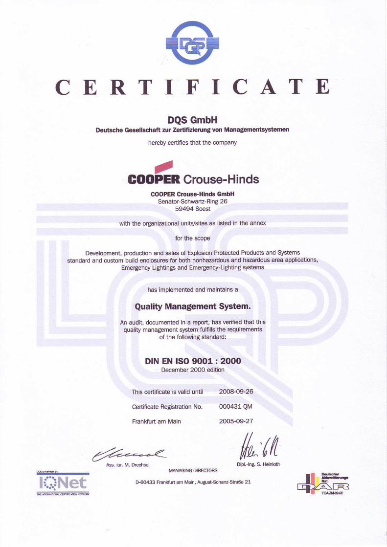
C E R T I F I C A T EDQS GmbH
Deutsche G€€tlschaft alr ZertfizigunS von Managenentsyatamon
hereby certifies that the company
GOO Crouse-Hinds/PER
COOPER Oouse-Hinds GmbHSenatorschwaE-Ring 26
59494 Soest
with the organEational univsites as listed in the annex
for the scope
Development, productjon and sales of Explooion Protected Prcducts and Systemsstandard and custom build enclosures for both nonhazardous and hazadous area applications,
Emergency Ughtings and Emergency-Lrenungsystems
has implemented and maintains a
Quality Managlement System.
An audit, documented in a rcport, has ledfied that thisquality management system fulfills tho requiEments
of the following standard:
DIN EN ISO 9OO1 : 20OODecember 2000 editron
thi6 certincate is vahd until 2004-09-26
Ceftific€te Regstration No-
F-dnkfurt am ldain
000,|:,1QM
2005'0927
ls, iu. M, Dcdrsel{^'ttt
MANAGING OIRECTOfiS
0$043 Franktun an Man, Arglst'Schdnz-St?6e 21l{}Net
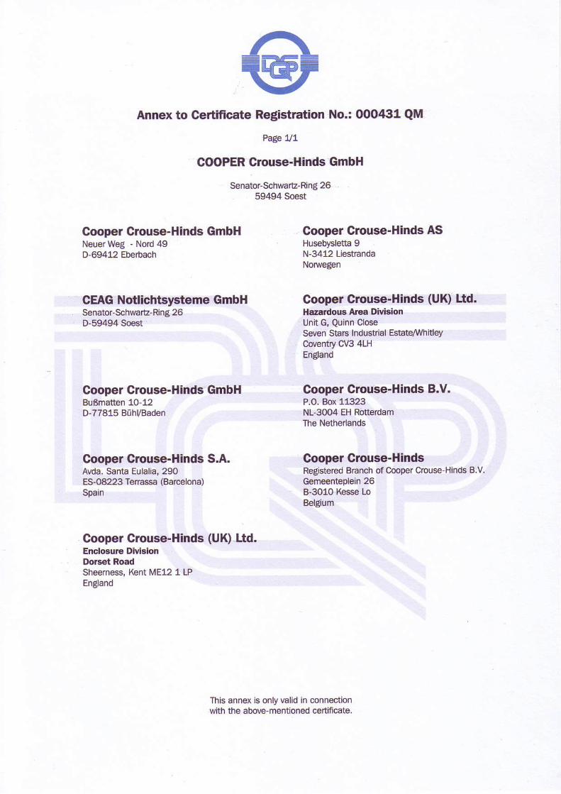
@Annex to Certificate Registration No.: (X)O4:11 QM
>age 117
COOPER Crouse-Hinds GmbH
Senator-Sch\,!€t_Ring 2659494 S'oest
Cooper Crouse-Hinds GmbH Gooper Clouse-Hinds ASNeuer weg - Nord 49 Hus€bysletta 9D-69412 Ebebach N'3412 Uestranda
NOlwegen
CEAG Notlichtslrstemo GmbH Cooper Crouse-Hinds (UK) Ltd.Senator'SchwarE-Ring 26 llarardous Arca DivialonD"59494 Soest ljnit G, Quinn close
Seven Stars Industnal Estat4whitleycoventry CV3 4LHEngland
Cooper Crouse-Hinds GmbH Cooper Clouse-Hinds B.V.BuBmatten 10-12 P.O. Box 1(]23D'77815 B0huBaden NL-3004 EH Rotterdam
The Netherlands
Coopel Crouse-Hinds S.A. Cooper Clouse-HindsAvda. Santa Eulalia, 290 Registercd BFnch of Cooper Crcuse-Hinds B.V.ES-O8223 Tenassa (Barcelona) GemeenGplein 26Spain B-3010lGsse Lo
Belgum
Cooper Crouse-Hinds (UK) Ltd.Encloaure DMslonDo.set RoadSheemess, Kent lVE12 1 LPEnEland
This annex is only valid in connectionwith the above-mentioned cenificate.
Enclosure / terminal assRefer to our website: ww
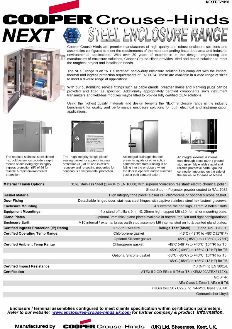
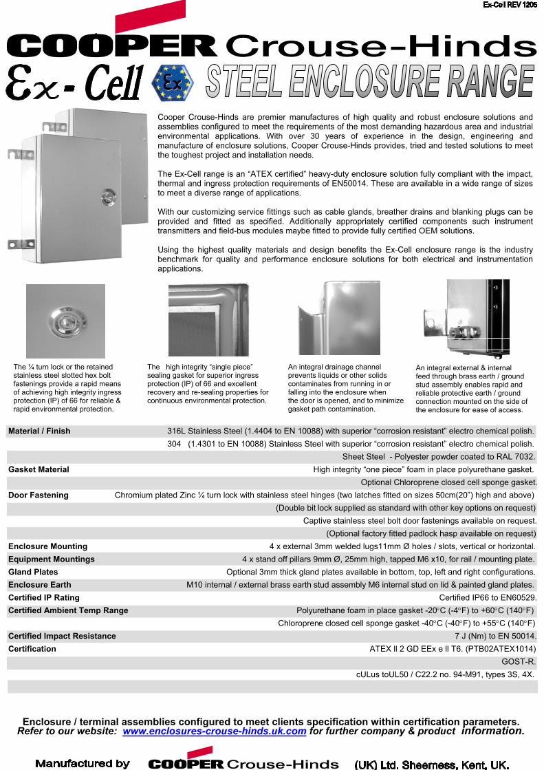
An integral drainage channel prevents liquids or other solids contaminates from running in or falling into the enclosure when the door is opened, and to minimize
ew
The high integrity “single piece” sealing gasket for superior ingress protection (IP) of 66 and excellent recovery and re-sealing properties for continuous environmental protection.
gasket path contamination.
Material / Finish Options 316L Stainless Steel (1.4404 to EN 10088) with superior “corrosion resistant” electro chemical polish. Sheet Steel - Polyester powder coated to RAL 7032. Gasket Material High integrity “one piece” closed cell chloroprene or optional silicone gasket. Door Fixing Detachable hinged door, stainless steel hinges with captive stainless steel hex fastening screws. Enclosure Mounting 4 x external welded lugs, 11mm Ø holes / slots. Equipment Mountings 4 x stand off pillars 9mm Ø, 25mm high, tapped M6 x10, for rail or mounting plate. Gland Plates Optional 3mm thick gland plates available in bottom, top, left and right configurations. Enclosure Earth M10 internal / external brass earth stud assembly M6 internal stud on lid & painted gland plates. Certified Ingress Protection (IP) Rating IP66 to EN60529. Deluge Test (Shell) Spec. No. DTS 01. Certified Operating Temp Range Chloroprene gasket -45°C (-49°F) to +80°C (176°F) Optional Silicone gasket -65°C (-85°F) to +135°C (-275°F) Certified Ambient Temp Range Chloroprene gasket -45°C (-49°F) to +40°C (104°F) for T6. -45°C (-49°F) to +55°C (131°F) for T5. Optional Silicone gasket -65°C (-85°C) to +40°C (104°F) for T6. -65°C (-85°F) to +55°C (131°F) for T5. Certified Impact Resistance 7 J (Nm) to EN 50014. Certification ATEX ll 2 GD EEx e II T6 or T5. (KEMA99ATEX3172X). GOST-R. AEx Class 1 Zone 1 AEx e II T6. cULus toUL50 / C22.2 no. 94-M91, types 3S, 4X. Germanischer Lloyd.
The retained stainless steel slotted hex bolt fastenings provide a rapid means of achieving high integrity ingress protection (IP) of 66 for reliable & rapid environmental protection.
mblies configured to meet clients specification within ce.enclosures-crouse-hinds.uk.com for further company &
An integral external & internal feed through brass earth / ground stud assembly enables rapid and reliable protective earth / ground connection mounted on the side of the enclosure for ease of access.
Cooper Crouse-Hinds are premier manufactures of high quality and robust enclosure solutions andassemblies configured to meet the requirements of the most demanding hazardous area and industrialenvironmental applications. With over 30 years of experience in the design, engineering andmanufacture of enclosure solutions, Cooper Crouse-Hinds provides, tried and tested solutions to meetthe toughest project and installation needs. The NEXT range is an “ATEX certified” heavy-duty enclosure solution fully compliant with the impact,thermal and ingress protection requirements of EN50014. These are available in a wide range of sizesto meet a diverse range of applications. With our customizing service fittings such as cable glands, breather drains and blanking plugs can beprovided and fitted as specified. Additionally appropriately certified components such instrumenttransmitters and field-bus modules maybe fitted to provide fully certified OEM solutions. Using the highest quality materials and design benefits the NEXT enclosure range is the industrybenchmark for quality and performance enclosure solutions for both electrical and instrumentationapplications.
rtification parameters. product information.
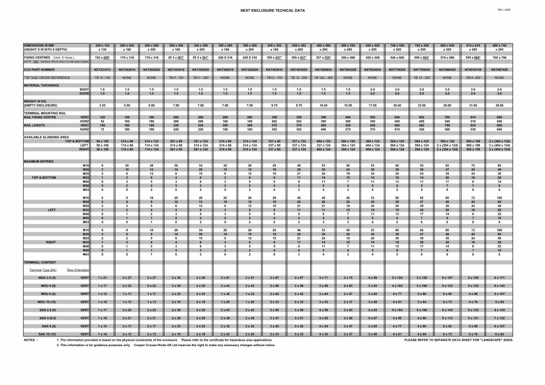
NEXT ENCLOSURE TECHICAL DATA REV. 0205
DIMENSIONS IN MM 229 x 152 260 x 260 260 x 260 306 x 306 306 x 306 380 x 260 380 x 260 458 x 382 458 x 382 480 x 480 500 x 350 620 x 450 740 x 550 762 x 508 860 x 640 914 x 610 980 x 740(HEIGHT X W IDTH X DEPTH) x 130 x 160 x 205 x 160 x 205 x 160 x 205 x 160 x 205 x 205 x 205 x 205 x 205 x 205 x 205 x 205 x 205
FIXING CENTRES (Vert. X Horiz.) 152 x 208* 170 x 316 170 x 316 20 3 x 361* 20 3 x 361* 250 X 316 250 X 316 305 x 437* 305 x 437* 327 x 535* 350 x 406 450 x 506 540 x 606 508 x 564* 570 x 696 559 x 666* 700 x 796NOTE : 123* - Subtract 30mm when no side gland plates
CCH PART NUMBER NXT221513 NXT262616 NXT262620 NXT303016 NXT303020 NXT382616 NXT382620 NXT453816 NXT453820 NXT484820 NXT503520 NXT624520 NXT745520 NXT765020 NXT866420 NTX916120 NXT987420
"TB" SIZE CROSS REFERENCE TB 10 -130 NONE NONE TB11 -150 TB11 - 200 NONE NONE TB12 - 150 TB 12 - 200 TB 12A - 200 NONE NONE NONE TB 13 - 200 NONE TB14 -200 NONE
MATERIAL THICKNESS BODY 1.5 1.5 1.5 1.5 1.5 1.5 1.5 1.5 1.5 1.5 1.5 2.0 2.0 2.0 2.0 2.0 2.0DOOR 1.5 1.5 1.5 1.5 1.5 1.5 1.5 1.5 1.5 1.5 1.5 2.0 2.0 2.0 2.0 2.0 2.0
WEIGHT IN KG. (EMPTY ENCLOSURE) 3.25 5.50 5.50 7.00 7.00 7.00 7.00 9.75 9.75 10.40 10.50 17.00 30.40 23.50 29.00 31.00 38.00
TERMINAL MOUNTING RAIL RAIL FIXING CENTRE VERT 129 160 160 206 206 280 280 358 358 380 400 520 640 662 760 814 880
HORZ 52 160 160 206 206 180 180 282 282 380 260 350 450 408 540 510 640RAIL LENGTH VERT 149 180 180 226 226 300 300 378 378 400 420 540 660 682 780 834 900
HORZ 72 180 180 226 226 160 160 302 302 400 270 370 470 428 560 530 660
AVAILABLE GLANDING AREA TOP & BOTTOM 58 x 108 214 x 80 214 x 124 261 x 80 261 x 124 214 x 80 214 x 124 337 x 80 337 x 124 404 x 124 304 x 124 404 x 124 504 x 124 404 x 124 594 x 124 566 x 108 2 x (304 x 124)
LEFT 58 x 108 114 x 80 114 x 124 214 x 80 214 x 124 214 x 80 214 x 124 337 x 80 337 x 124 337 x 124 304 x 124 404 x 124 504 x 124 594 x 124 2 x (304 x 124) 566 x 108 2 x (404 x 124)RIGHT 58 x 108 114 x 80 114 x 124 261 x 80 261 x 124 214 x 80 214 x 124 337 x 80 337 x 124 404 x 124 304 x 124 404 x 124 504 x 124 594 x 124 2 x (304 x 124) 566 x 108 2 x (404 x 124)
MAXIMUM ENTRIESM16 6 20 28 26 34 20 28 29 46 53 40 53 60 53 82 72 80M20 3 10 15 14 20 10 15 18 26 30 24 30 39 30 47 42 48M25 2 6 12 8 15 6 12 10 21 24 18 24 30 24 39 24 36
TOP & BOTTOM M32 1 3 6 4 8 3 6 6 11 14 10 14 18 14 20 18 20M40 0 3 5 3 6 3 5 5 9 11 7 11 13 11 17 8 14M50 0 2 2 3 3 2 2 4 4 5 4 5 6 5 7 7 8M63 0 0 2 0 2 0 2 0 3 4 3 4 5 4 6 6 6
M16 6 9 18 20 28 20 28 29 46 46 40 53 60 82 80 72 106M20 3 6 9 10 15 10 15 18 26 26 24 30 39 47 48 42 60M25 2 3 5 6 12 6 12 10 21 21 18 24 30 39 36 24 48
LEFT M32 1 2 4 3 6 3 6 6 11 11 10 14 18 20 20 18 28M40 0 1 2 3 5 3 5 5 9 9 7 11 13 17 14 8 22M50 0 1 1 2 2 2 2 4 4 4 4 5 6 7 8 7 10M63 0 0 1 0 2 0 2 0 3 3 3 4 5 6 6 6 8
M16 6 9 18 26 34 20 28 29 46 53 40 53 60 82 80 72 106M20 3 6 9 14 20 10 15 18 26 30 24 30 39 47 48 42 60M25 2 2 5 8 15 6 12 10 21 24 18 24 30 39 36 24 48
RIGHT M32 1 3 4 4 8 3 6 6 11 14 10 14 18 20 20 18 28M40 0 1 2 3 6 3 5 5 9 11 7 11 13 17 14 8 22M50 0 1 1 3 3 2 2 4 4 5 4 5 6 7 8 7 10M63 0 0 1 0 2 0 2 0 3 4 3 4 5 6 6 6 8
TERMINAL CONTENT
Terminal Type (thk) Row Orientation
WDU 2.5 (5) VERT 1 x 21 2 x 27 2 x 27 2 x 36 2 x 36 2 x 51 2 x 51 2 x 67 2 x 67 3 x 71 3 x 75 4 x 99 5 x 124 3 x 128 6 x 147 5 x 158 6 x 171
WDU 4 (6) VERT 1 x 17 2 x 23 2 x 23 2 x 30 2 x 30 2 x 43 2 x 43 2 x 56 2 x 56 3 x 59 2 x 63 3 x 83 4 x 10³ 3 x 10⁶ 5 x 123 5 x 132 6 x 143
WDU 6 (8) VERT 1 x 13 1 x 17 1 x 17 2 x 23 2 x 23 1 x 32 1 x 32 2 x 42 2 x 42 3 x 44 2 x 47 3 x 62 4 x 77 3 x 80 5 x 92 4 x 99 5 x 10⁷
WDU 10 (10) VERT 1 x 10 1 x 13 1 x 13 2 x 18 2 x 18 1 x 25 1 x 25 2 x 33 2 x 33 3 x 35 2 x 37 3 x 49 4 x 61 3 x 64 4 x 73 4 x 79 5 x 85
SAK 2.5 (6) VERT 1 x 17 2 x 23 2 x 23 2 x 30 2 x 30 2 x 43 2 x 43 3 x 56 3 x 56 4 x 59 3 x 63 4 x 83 5 x 10³ 4 x 10⁶ 6 x 143 5 x 132 8 x 143
SAK 4 (6.5) VERT 1 x 16 2 x 21 2 x 21 2 x 28 2 x 28 2 x 39 2 x 39 3 x 51 3 x 51 4 x 55 3 x 58 4 x 67 4 x 95 4 x 98 5 x 113 5 x 121 7 x 132
SAK 6 (8) VERT 1 x 13 2 x 17 2 x 17 2 x 23 2 x 23 2 x 32 2 x 32 3 x 42 3 x 42 4 x 44 3 x 47 3 x 62 4 x 77 4 x 80 5 x 92 5 x 99 6 x 10⁷
SAK 10 (10) VERT 1 x 10 2 x 13 2 x 13 2 x 18 2 x 18 2 x 25 2 x 25 3 x 33 3 x 33 4 x 35 3 x 37 3 x 49 4 x 61 4 x 64 5 x 73 5 x 79 6 x 85
NOTES : - 1. The information provided is based on the physical constraints of the enclosure. Please refer to the certificate for hazardous area applications. PLEASE REFER TO SEPARATE DATA SHEET FOR "LANDSCAPE" SIZES.2. This information is for guidance purposes only. Cooper Crouse-Hinds UK Ltd reserves the right to make any necessary changes without notice
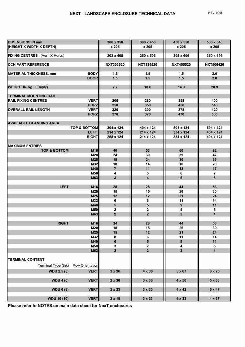
NEXT - LANDSCAPE ENCLOSURE TECHNICAL DATA REV. 0205
DIMENSIONS IN mm 306 x 350 380 x 450 458 x 550 500 x 640(HEIGHT X WIDTH X DEPTH) x 205 x 205 x 205 x 205
FIXING CENTRES (Vert. X Horiz.) 203 x 405 250 x 506 305 x 606 350 x 696
CCH PART REFERENCE NXT303520 NXT384520 NXT455520 NXT506420
MATERIAL THICKNESS, mm BODY 1.5 1.5 1.5 2.0DOOR 1.5 1.5 1.5 2.0
WEIGHT IN Kg (Empty) 7.7 10.6 14.9 20.9
TERMINAL MOUNTING RAIL RAIL FIXING CENTRES VERT 206 280 358 400
HORZ 250 350 450 540OVERALL RAIL LENGTH VERT 226 300 378 420
HORZ 270 370 470 560
AVAILABLE GLANDING AREA TOP & BOTTOM 304 x 124 404 x 124 504 x 124 594 x 124
LEFT 214 x 124 214 x 124 334 x 124 404 x 124RIGHT 258 x 124 214 x 124 334 x 124 404 x 124
MAXIMUM ENTRIESTOP & BOTTOM M16 40 53 60 82
M20 24 30 39 47M25 18 24 30 39M32 10 14 18 20M40 7 11 13 17M50 4 5 6 7M63 3 4 5 6
LEFT M16 28 28 44 53M20 15 15 26 30M25 12 12 21 24M32 6 6 11 14M40 5 5 9 11M50 2 2 4 5M63 2 2 3 4
RIGHT M16 34 28 44 53M20 18 15 26 30M25 15 12 21 24M32 8 6 11 14M40 6 5 9 11M50 3 2 4 5M63 2 2 3 4
TERMINAL CONTENT Terminal Type (thk) Row Orientation
WDU 2.5 (5) VERT 3 x 36 4 x 36 5 x 67 6 x 75
WDU 4 (6) VERT 2 x 30 3 x 36 4 x 56 5 x 63
WDU 6 (8) VERT 2 x 23 3 x 30 4 x 42 5 x 47
WDU 10 (10) VERT 2 x 18 3 x 23 4 x 33 4 x 37
Please refer to NOTES on main data sheet for NexT enclosures
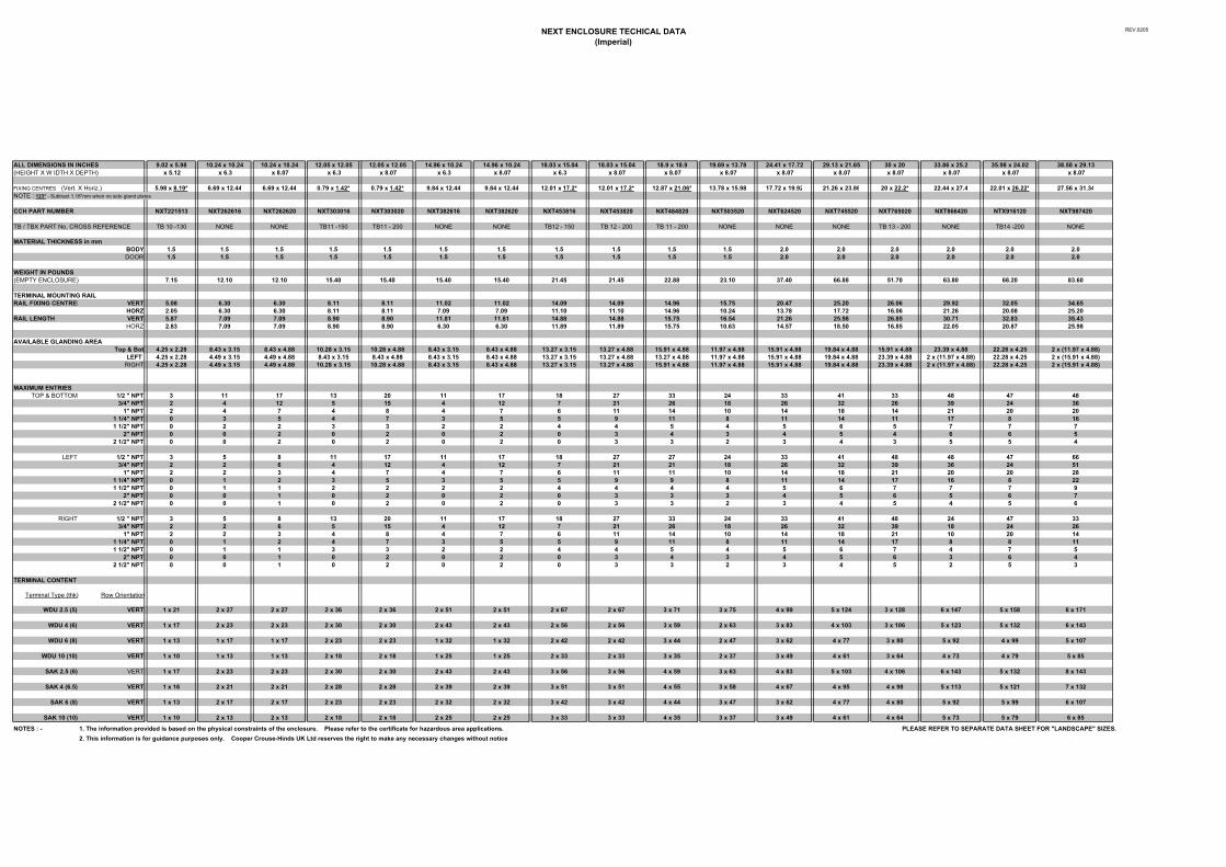
NEXT ENCLOSURE TECHICAL DATA(Imperial)
REV.0205
ALL DIMENSIONS IN INCHES 9.02 x 5.98 10.24 x 10.24 10.24 x 10.24 12.05 x 12.05 12.05 x 12.05 14.96 x 10.24 14.96 x 10.24 18.03 x 15.04 18.03 x 15.04 18.9 x 18.9 19.69 x 13.78 24.41 x 17.72 29.13 x 21.65 30 x 20 33.86 x 25.2 35.98 x 24.02 38.58 x 29.13(HEIGHT X W IDTH X DEPTH) x 5.12 x 6.3 x 8.07 x 6.3 x 8.07 x 6.3 x 8.07 x 6.3 x 8.07 x 8.07 x 8.07 x 8.07 x 8.07 x 8.07 x 8.07 x 8.07 x 8.07
FIXING CENTRES (Vert. X Horiz.) 5.98 x 8.19* 6.69 x 12.44 6.69 x 12.44 0.79 x 1.42* 0.79 x 1.42* 9.84 x 12.44 9.84 x 12.44 12.01 x 17.2* 12.01 x 17.2* 12.87 x 21.06* 13.78 x 15.98 17.72 x 19.92 21.26 x 23.86 20 x 22.2* 22.44 x 27.4 22.01 x 26.22* 27.56 x 31.34NOTE : 123* - Subtract 1.18"mm when no side gland plates
CCH PART NUMBER NXT221513 NXT262616 NXT262620 NXT303016 NXT303020 NXT382616 NXT382620 NXT453816 NXT453820 NXT484820 NXT503520 NXT624520 NXT745520 NXT765020 NXT866420 NTX916120 NXT987420
TB / TBX PART No. CROSS REFERENCE TB 10 -130 NONE NONE TB11 -150 TB11 - 200 NONE NONE TB12 - 150 TB 12 - 200 TB 11 - 200 NONE NONE NONE TB 13 - 200 NONE TB14 -200 NONE
MATERIAL THICKNESS in mmBODY 1.5 1.5 1.5 1.5 1.5 1.5 1.5 1.5 1.5 1.5 1.5 2.0 2.0 2.0 2.0 2.0 2.0DOOR 1.5 1.5 1.5 1.5 1.5 1.5 1.5 1.5 1.5 1.5 1.5 2.0 2.0 2.0 2.0 2.0 2.0
WEIGHT IN POUNDS(EMPTY ENCLOSURE) 7.15 12.10 12.10 15.40 15.40 15.40 15.40 21.45 21.45 22.88 23.10 37.40 66.88 51.70 63.80 68.20 83.60
TERMINAL MOUNTING RAIL RAIL FIXING CENTRES VERT 5.08 6.30 6.30 8.11 8.11 11.02 11.02 14.09 14.09 14.96 15.75 20.47 25.20 26.06 29.92 32.05 34.65
HORZ 2.05 6.30 6.30 8.11 8.11 7.09 7.09 11.10 11.10 14.96 10.24 13.78 17.72 16.06 21.26 20.08 25.20RAIL LENGTH VERT 5.87 7.09 7.09 8.90 8.90 11.81 11.81 14.88 14.88 15.75 16.54 21.26 25.98 26.85 30.71 32.83 35.43
HORZ 2.83 7.09 7.09 8.90 8.90 6.30 6.30 11.89 11.89 15.75 10.63 14.57 18.50 16.85 22.05 20.87 25.98
AVAILABLE GLANDING AREA Top & Bot 4.25 x 2.28 8.43 x 3.15 8.43 x 4.88 10.28 x 3.15 10.28 x 4.88 8.43 x 3.15 8.43 x 4.88 13.27 x 3.15 13.27 x 4.88 15.91 x 4.88 11.97 x 4.88 15.91 x 4.88 19.84 x 4.88 15.91 x 4.88 23.39 x 4.88 22.28 x 4.25 2 x (11.97 x 4.88)
LEFT 4.25 x 2.28 4.49 x 3.15 4.49 x 4.88 8.43 x 3.15 8.43 x 4.88 8.43 x 3.15 8.43 x 4.88 13.27 x 3.15 13.27 x 4.88 13.27 x 4.88 11.97 x 4.88 15.91 x 4.88 19.84 x 4.88 23.39 x 4.88 2 x (11.97 x 4.88) 22.28 x 4.25 2 x (15.91 x 4.88)RIGHT 4.25 x 2.28 4.49 x 3.15 4.49 x 4.88 10.28 x 3.15 10.28 x 4.88 8.43 x 3.15 8.43 x 4.88 13.27 x 3.15 13.27 x 4.88 15.91 x 4.88 11.97 x 4.88 15.91 x 4.88 19.84 x 4.88 23.39 x 4.88 2 x (11.97 x 4.88) 22.28 x 4.25 2 x (15.91 x 4.88)
MAXIMUM ENTRIESTOP & BOTTOM 1/2 " NPT 3 11 17 13 20 11 17 18 27 33 24 33 41 33 48 47 48
3/4" NPT 2 4 12 5 15 4 12 7 21 26 18 26 32 26 39 24 361" NPT 2 4 7 4 8 4 7 6 11 14 10 14 18 14 21 20 20
1 1/4" NPT 0 3 5 4 7 3 5 5 9 11 8 11 14 11 17 8 161 1/2" NPT 0 2 2 3 3 2 2 4 4 5 4 5 6 5 7 7 7
2" NPT 0 0 2 0 2 0 2 0 3 4 3 4 5 4 6 6 52 1/2" NPT 0 0 2 0 2 0 2 0 3 3 2 3 4 3 5 5 4
LEFT 1/2 " NPT 3 5 8 11 17 11 17 18 27 27 24 33 41 48 48 47 663/4" NPT 2 2 6 4 12 4 12 7 21 21 18 26 32 39 36 24 51
1" NPT 2 2 3 4 7 4 7 6 11 11 10 14 18 21 20 20 281 1/4" NPT 0 1 2 3 5 3 5 5 9 9 8 11 14 17 16 8 221 1/2" NPT 0 1 1 2 2 2 2 4 4 4 4 5 6 7 7 7 9
2" NPT 0 0 1 0 2 0 2 0 3 3 3 4 5 6 5 6 72 1/2" NPT 0 0 1 0 2 0 2 0 3 3 2 3 4 5 4 5 6
RIGHT 1/2 " NPT 3 5 8 13 20 11 17 18 27 33 24 33 41 48 24 47 333/4" NPT 2 2 6 5 15 4 12 7 21 26 18 26 32 39 18 24 26
1" NPT 2 2 3 4 8 4 7 6 11 14 10 14 18 21 10 20 141 1/4" NPT 0 1 2 4 7 3 5 5 9 11 8 11 14 17 8 8 111 1/2" NPT 0 1 1 3 3 2 2 4 4 5 4 5 6 7 4 7 5
2" NPT 0 0 1 0 2 0 2 0 3 4 3 4 5 6 3 6 42 1/2" NPT 0 0 1 0 2 0 2 0 3 3 2 3 4 5 2 5 3
TERMINAL CONTENT
Terminal Type (thk) Row Orientation
WDU 2.5 (5) VERT 1 x 21 2 x 27 2 x 27 2 x 36 2 x 36 2 x 51 2 x 51 2 x 67 2 x 67 3 x 71 3 x 75 4 x 99 5 x 124 3 x 128 6 x 147 5 x 158 6 x 171
WDU 4 (6) VERT 1 x 17 2 x 23 2 x 23 2 x 30 2 x 30 2 x 43 2 x 43 2 x 56 2 x 56 3 x 59 2 x 63 3 x 83 4 x 10³ 3 x 10⁶ 5 x 123 5 x 132 6 x 143
WDU 6 (8) VERT 1 x 13 1 x 17 1 x 17 2 x 23 2 x 23 1 x 32 1 x 32 2 x 42 2 x 42 3 x 44 2 x 47 3 x 62 4 x 77 3 x 80 5 x 92 4 x 99 5 x 10⁷
WDU 10 (10) VERT 1 x 10 1 x 13 1 x 13 2 x 18 2 x 18 1 x 25 1 x 25 2 x 33 2 x 33 3 x 35 2 x 37 3 x 49 4 x 61 3 x 64 4 x 73 4 x 79 5 x 85
SAK 2.5 (6) VERT 1 x 17 2 x 23 2 x 23 2 x 30 2 x 30 2 x 43 2 x 43 3 x 56 3 x 56 4 x 59 3 x 63 4 x 83 5 x 10³ 4 x 10⁶ 6 x 143 5 x 132 8 x 143
SAK 4 (6.5) VERT 1 x 16 2 x 21 2 x 21 2 x 28 2 x 28 2 x 39 2 x 39 3 x 51 3 x 51 4 x 55 3 x 58 4 x 67 4 x 95 4 x 98 5 x 113 5 x 121 7 x 132
SAK 6 (8) VERT 1 x 13 2 x 17 2 x 17 2 x 23 2 x 23 2 x 32 2 x 32 3 x 42 3 x 42 4 x 44 3 x 47 3 x 62 4 x 77 4 x 80 5 x 92 5 x 99 6 x 10⁷
SAK 10 (10) VERT 1 x 10 2 x 13 2 x 13 2 x 18 2 x 18 2 x 25 2 x 25 3 x 33 3 x 33 4 x 35 3 x 37 3 x 49 4 x 61 4 x 64 5 x 73 5 x 79 6 x 85
NOTES : - 1. The information provided is based on the physical constraints of the enclosure. Please refer to the certificate for hazardous area applications. PLEASE REFER TO SEPARATE DATA SHEET FOR "LANDSCAPE" SIZES.2. This information is for guidance purposes only. Cooper Crouse-Hinds UK Ltd reserves the right to make any necessary changes without notice
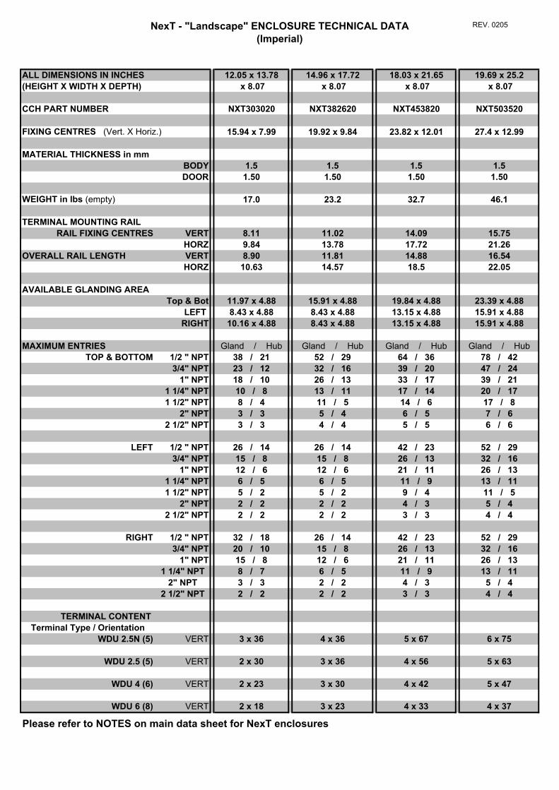
NexT - "Landscape" ENCLOSURE TECHNICAL DATA(Imperial)
REV. 0205
ALL DIMENSIONS IN INCHES 12.05 x 13.78 14.96 x 17.72 18.03 x 21.65 19.69 x 25.2(HEIGHT X WIDTH X DEPTH) x 8.07 x 8.07 x 8.07 x 8.07
CCH PART NUMBER NXT303020 NXT382620 NXT453820 NXT503520
FIXING CENTRES (Vert. X Horiz.) 15.94 x 7.99 19.92 x 9.84 23.82 x 12.01 27.4 x 12.99
MATERIAL THICKNESS in mmBODY 1.5 1.5 1.5 1.5DOOR 1.50 1.50 1.50 1.50
WEIGHT in lbs (empty) 17.0 23.2 32.7 46.1
TERMINAL MOUNTING RAIL RAIL FIXING CENTRES VERT 8.11 11.02 14.09 15.75
HORZ 9.84 13.78 17.72 21.26OVERALL RAIL LENGTH VERT 8.90 11.81 14.88 16.54
HORZ 10.63 14.57 18.5 22.05
AVAILABLE GLANDING AREA Top & Bot 11.97 x 4.88 15.91 x 4.88 19.84 x 4.88 23.39 x 4.88
LEFT 8.43 x 4.88 8.43 x 4.88 13.15 x 4.88 15.91 x 4.88RIGHT 10.16 x 4.88 8.43 x 4.88 13.15 x 4.88 15.91 x 4.88
MAXIMUM ENTRIES Gland / Hub Gland / Hub Gland / Hub Gland / HubTOP & BOTTOM 1/2 " NPT 38 / 21 52 / 29 64 / 36 78 / 42
3/4" NPT 23 / 12 32 / 16 39 / 20 47 / 241" NPT 18 / 10 26 / 13 33 / 17 39 / 21
1 1/4" NPT 10 / 8 13 / 11 17 / 14 20 / 171 1/2" NPT 8 / 4 11 / 5 14 / 6 17 / 8
2" NPT 3 / 3 5 / 4 6 / 5 7 / 62 1/2" NPT 3 / 3 4 / 4 5 / 5 6 / 6
LEFT 1/2 " NPT 26 / 14 26 / 14 42 / 23 52 / 293/4" NPT 15 / 8 15 / 8 26 / 13 32 / 16
1" NPT 12 / 6 12 / 6 21 / 11 26 / 131 1/4" NPT 6 / 5 6 / 5 11 / 9 13 / 111 1/2" NPT 5 / 2 5 / 2 9 / 4 11 / 5
2" NPT 2 / 2 2 / 2 4 / 3 5 / 42 1/2" NPT 2 / 2 2 / 2 3 / 3 4 / 4
RIGHT 1/2 " NPT 32 / 18 26 / 14 42 / 23 52 / 293/4" NPT 20 / 10 15 / 8 26 / 13 32 / 16
1" NPT 15 / 8 12 / 6 21 / 11 26 / 131 1/4" NPT 8 / 7 6 / 5 11 / 9 13 / 11
2" NPT 3 / 3 2 / 2 4 / 3 5 / 42 1/2" NPT 2 / 2 2 / 2 3 / 3 4 / 4
TERMINAL CONTENT Terminal Type / Orientation
WDU 2.5N (5) VERT 3 x 36 4 x 36 5 x 67 6 x 75
WDU 2.5 (5) VERT 2 x 30 3 x 36 4 x 56 5 x 63
WDU 4 (6) VERT 2 x 23 3 x 30 4 x 42 5 x 47
WDU 6 (8) VERT 2 x 18 3 x 23 4 x 33 4 x 37
Please refer to NOTES on main data sheet for NexT enclosures
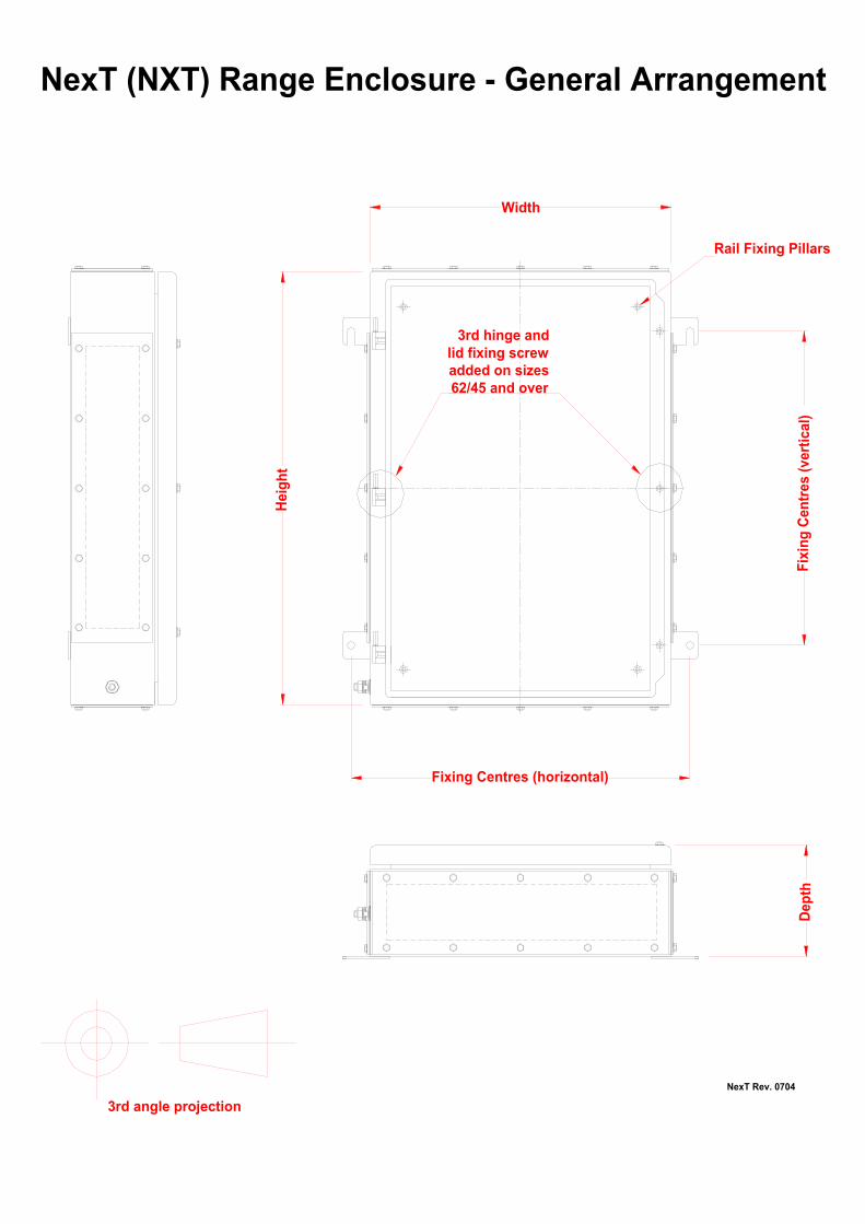
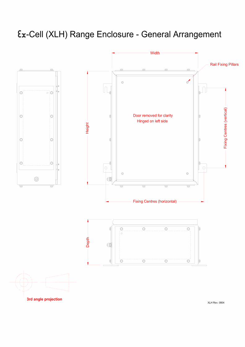
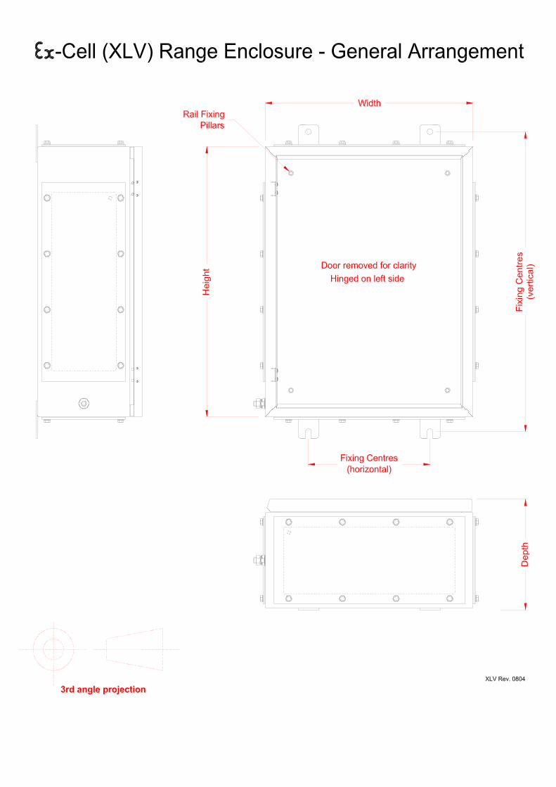
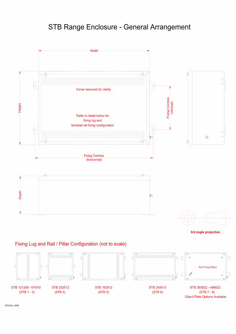
Width
Hei
ght
Dep
thFi
Cen
tres
(ver
tical
)
Fixing Centres (horizontal)
Rail Fixing Pillars
3rd hinge and lid fixing screwadded on sizes62/45 and over
3rd angle projection
NexT (NXT) Range Enclosure - General Arrangement
NexT Rev. 0704
Enclosure / terminal assembliRefer to our website: www.enc
sin
An integral drainage channel prevents liquids or other solids contaminates from running in or falling into the enclosure when the door is opened, and to minimize
The high integrity “single piece” sealing gasket for superior ingress protection (IP) of 66 and excellent recovery and re-sealing properties for continuous environmental protection.
gasket path contamination.
The ¼ turn lock or the retained stainless steel slotted hex bolt fastenings provide a rapid means of achieving high integrity ingress protection (IP) of 66 for reliable & rapid environmental protection.
Material / Finish 316L Stainless Steel (1.4404 to EN 10088) with superior “corrosion resistant” electro chemical polish. 304 (1.4301 to EN 10088) Stainless Steel with superior “corrosion resistant” electro chemical polish. Sheet Steel - Polyester powder coated to RAL 7032. Gasket Material High integrity “one piece” foam in place polyurethane gasket. Optional Chloroprene closed cell sponge gasket. Door Fastening Chromium plated Zinc ¼ turn lock with stainless steel hinges (two latches fitted on sizes 50cm(20”) high and above) (Double bit lock supplied as standard with other key options on request) Captive stainless steel bolt door fastenings available on request. (Optional factory fitted padlock hasp available on request) Enclosure Mounting 4 x external 3mm welded lugs11mm Ø holes / slots, vertical or horizontal. Equipment Mountings 4 x stand off pillars 9mm Ø, 25mm high, tapped M6 x10, for rail / mounting plate. Gland Plates Optional 3mm thick gland plates available in bottom, top, left and right configurations. Enclosure Earth M10 internal / external brass earth stud assembly M6 internal stud on lid & painted gland plates. Certified IP Rating Certified IP66 to EN60529. Certified Ambient Temp Range Polyurethane foam in place gasket -20°C (-4°F) to +60°C (140°F) Chloroprene closed cell sponge gasket -40°C (-40°F) to +55°C (140°F) Certified Impact Resistance 7 J (Nm) to EN 50014. Certification ATEX ll 2 GD EEx e ll T6. (PTB02ATEX1014) GOST-R. cULus toUL50 / C22.2 no. 94-M91, types 3S, 4X.
es configured to meet clients specification within celosures-crouse-hinds.uk.com for further company &
An integral external & internal feed through brass earth / ground stud assembly enables rapid and reliable protective earth / ground connection mounted on the side of the enclosure for ease of access.
Cooper Crouse-Hinds are premier manufactures of high quality and robust enclosure solutions andassemblies configured to meet the requirements of the most demanding hazardous area and industrialenvironmental applications. With over 30 years of experience in the design, engineering andmanufacture of enclosure solutions, Cooper Crouse-Hinds provides, tried and tested solutions to meetthe toughest project and installation needs. The Ex-Cell range is an “ATEX certified” heavy-duty enclosure solution fully compliant with the impact,thermal and ingress protection requirements of EN50014. These are available in a wide range of sizesto meet a diverse range of applications. With our customizing service fittings such as cable glands, breather drains and blanking plugs can beprovided and fitted as specified. Additionally appropriately certified components such instrumenttransmitters and field-bus modules maybe fitted to provide fully certified OEM solutions. U ng the highest quality materials and design benefits the Ex-Cell enclosure range is the industrybe chmark for quality and performance enclosure solutions for both electrical and instrumentationapplications.
rtification parameters. product information.
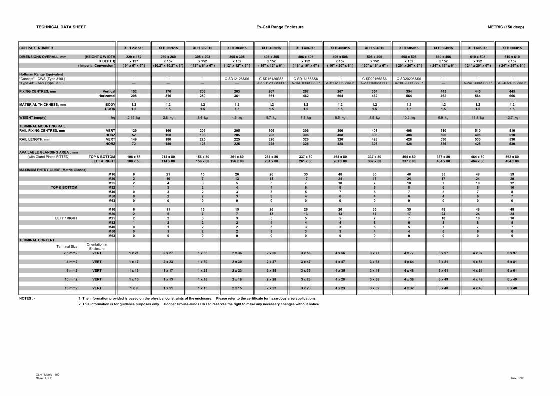
TECHNICAL DATA SHEET Ex-Cell Range Enclosure METRIC (150 deep)
CCH PART NUMBER XLH 231513 XLH 262615 XLH 302015 XLH 303015 XLH 403015 XLH 404015 XLH 405015 XLH 504015 XLH 505015 XLH 604015 XLH 605015 XLH 606015
DIMENSIONS OVERALL, mm (HEIGHT X W IDTH 229 x 152 260 x 260 305 x 203 305 x 305 406 x 305 406 x 406 406 x 508 508 x 406 508 x 508 610 x 406 610 x 508 610 x 610X DEPTH) x 127 x 152 x 152 x 152 x 152 x 152 x 152 x 152 x 152 x 152 x 152 x 152
( Imperial Conversion ) ( 9" x 6" x 5" ) (10.2" x 10.2" x 6") ( 12" x 8" x 6" ) ( 12" x 12" x 6" ) ( 16" x 12" x 6" ) ( 16" x 16" x 6" ) ( 16" x 20" x 6" ) ( 20" x 16" x 6" ) ( 20" x 20" x 6" ) ( 24" x 16" x 6" ) ( 24" x 20" x 6" ) ( 24" x 24" x 6" )
Hoffman Range Equivalent"Concept" - CWS (Type 316L) --- --- --- C-SD12126SS6 C-SD16126SS6 C-SD16166SS6 --- C-SD20166SS6 C-SD20206SS6 --- --- ---"Type 4X" - A4S (Type 316L) --- --- --- --- A-16H1206SS6LP A-16H1606SS6LP A-16H2006SS6LP A-20H1606SS6LP A-20H2006SS6LP --- A-24H2006SS6LP A-24H2406SS6LP
FIXING CENTRES, mm Vertical 152 170 203 203 267 267 267 354 354 445 445 445Horizontal 208 316 259 361 361 462 564 462 564 462 564 666
MATERIAL THICKNESS, mm BODY 1.2 1.2 1.2 1.2 1.2 1.2 1.2 1.2 1.2 1.2 1.2 1.2DOOR 1.5 1.5 1.5 1.5 1.5 1.5 1.5 1.5 1.5 1.5 1.5 1.5
WEIGHT (empty) kg 2.35 kg 2.8 kg 3.4 kg 4.6 kg 5.7 kg 7.1 kg 8.5 kg 8.5 kg 10.2 kg 9.9 kg 11.8 kg 13.7 kg
TERMINAL MOUNTING RAIL RAIL FIXING CENTRES, mm VERT 129 160 205 205 306 306 306 408 408 510 510 510
HORZ 52 160 103 205 205 306 408 306 408 306 408 510RAIL LENGTH, mm VERT 149 180 225 225 326 326 326 428 428 530 530 530
HORZ 72 180 123 225 225 326 428 326 428 326 428 530
AVAILABLE GLANDING AREA , mm(with Gland Plates FITTED) TOP & BOTTOM 108 x 58 214 x 80 156 x 80 261 x 80 261 x 80 337 x 80 464 x 80 337 x 80 464 x 80 337 x 80 464 x 80 562 x 80
LEFT & RIGHT 108 x 58 114 x 80 156 x 80 156 x 80 261 x 80 261 x 80 261 x 80 337 x 80 337 x 80 464 x 80 464 x 80 464 x 80
MAXIMUM ENTRY GUIDE (Metric Glands)M16 6 21 15 26 26 35 48 35 48 35 48 59M20 2 10 7 13 13 17 24 17 24 17 24 29M25 2 4 3 5 5 7 10 7 10 7 10 12
TOP & BOTTOM M32 1 3 2 4 4 6 8 6 8 6 8 10M40 0 3 2 3 3 5 7 5 7 5 7 8M50 0 2 2 3 3 4 6 4 6 4 6 7M63 0 0 0 0 0 0 0 0 0 0 0 0
M16 6 11 15 15 26 26 26 35 35 48 48 48M20 2 5 7 7 13 13 13 17 17 24 24 24
LEFT / RIGHT M25 2 2 3 3 5 5 5 7 7 10 10 10M32 1 2 2 2 4 4 4 6 6 8 8 8M40 0 1 2 2 3 3 3 5 5 7 7 7M50 0 1 2 2 3 3 3 4 4 6 6 6M63 0 0 0 0 0 0 0 0 0 0 0 0
TERMINAL CONTENT
Terminal Size Orientation in Enclosure
2.5 mm2 VERT 1 x 21 2 x 27 1 x 36 2 x 36 2 x 56 3 x 56 4 x 56 3 x 77 4 x 77 3 x 97 4 x 97 6 x 97
4 mm2 VERT 1 x 17 2 x 23 1 x 30 2 x 30 2 x 47 3 x 47 4 x 47 3 x 64 4 x 64 3 x 81 4 x 81 6 x 81
6 mm2 VERT 1 x 13 1 x 17 1 x 23 2 x 23 2 x 35 3 x 35 4 x 35 3 x 48 4 x 48 3 x 61 4 x 61 6 x 61
10 mm2 VERT 1 x 10 1 x 13 1 x 18 2 x 18 2 x 28 3 x 28 4 x 28 3 x 38 4 x 38 3 x 49 4 x 49 6 x 49
16 mm2 VERT 1 x 9 1 x 11 1 x 15 2 x 15 2 x 23 3 x 23 4 x 23 3 x 32 4 x 32 3 x 40 4 x 40 6 x 40
NOTES : - 1. The information provided is based on the physical constraints of the enclosure. Please refer to the certificate for hazardous area applications.2. This information is for guidance purposes only. Cooper Crouse-Hinds UK Ltd reserves the right to make any necessary changes without notice
XLH - Metric - 150Sheet 1 of 2 Rev. 0205
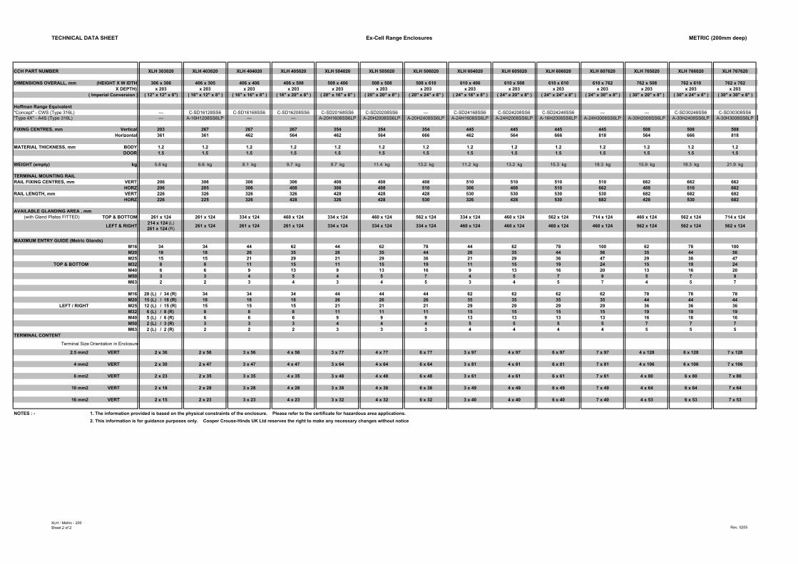
TECHNICAL DATA SHEET Ex-Cell Range Enclosures METRIC (200mm deep)
CCH PART NUMBER XLH 303020 XLH 403020 XLH 404020 XLH 405020 XLH 504020 XLH 505020 XLH 506020 XLH 604020 XLH 605020 XLH 606020 XLH 607620 XLH 765020 XLH 766020 XLH 767620
DIMENSIONS OVERALL, mm (HEIGHT X W IDTH 306 x 306 406 x 305 406 x 406 406 x 508 508 x 406 508 x 508 508 x 610 610 x 406 610 x 508 610 x 610 610 x 762 762 x 508 762 x 610 762 x 762X DEPTH) x 203 x 203 x 203 x 203 x 203 x 203 x 203 x 203 x 203 x 203 x 203 x 203 x 203 x 203
( Imperial Conversion ) ( 12" x 12" x 8") ( 16" x 12" x 8" ) ( 16" x 16" x 8" ) ( 16" x 20" x 8" ) ( 20" x 16" x 8" ) ( 20" x 20" x 8" ) ( 20" x 24" x 8" ) ( 24" x 16" x 8" ) ( 24" x 20" x 8" ) ( 24" x 24" x 8" ) ( 24" x 30" x 8" ) ( 30" x 20" x 8" ) ( 30" x 24" x 8" ) ( 30" x 30" x 8" )
Hoffman Range Equivalent"Concept" - CWS (Type 316L) --- C-SD16128SS6 C-SD16168SS6 C-SD16208SS6 C-SD20168SS6 C-SD20208SS6 --- C-SD24168SS6 C-SD24208SS6 C-SD24248SS6 --- --- C-SD30248SS6 C-SD30308SS6"Type 4X" - A4S (Type 316L) --- A-16H1208SS6LP --- --- A-20H1608SS6LP A-20H2008SS6LP A-20H2408SS6LP A-24H1608SS6LP A-24H2008SS6LP A-16H2006SS6LP A-24H3008SS6LP A-30H2008SS6LP A-30H2408SS6LP A-30H3008SS6LP
FIXING CENTRES, mm Vertical 203 267 267 267 354 354 354 445 445 445 445 508 508 508Horizontal 361 361 462 564 462 564 666 462 564 666 818 564 666 818
MATERIAL THICKNESS, mm BODY 1.2 1.2 1.2 1.2 1.2 1.2 1.2 1.2 1.2 1.2 1.2 1.2 1.2 1.2DOOR 1.5 1.5 1.5 1.5 1.5 1.5 1.5 1.5 1.5 1.5 1.5 1.5 1.5 1.5
WEIGHT (empty) kg 5.8 kg 6.6 kg 8.1 kg 9.7 kg 9.7 kg 11.4 kg 13.2 kg 11.2 kg 13.2 kg 15.3 kg 18.3 kg 15.9 kg 18.3 kg 21.9 kg
TERMINAL MOUNTING RAIL RAIL FIXING CENTRES, mm VERT 206 306 306 306 408 408 408 510 510 510 510 662 662 662
HORZ 206 205 306 408 306 408 510 306 408 510 662 408 510 662RAIL LENGTH, mm VERT 226 326 326 326 428 428 428 530 530 530 530 682 682 682
HORZ 226 225 326 428 326 428 530 326 428 530 682 428 530 682
AVAILABLE GLANDING AREA , mm(with Gland Plates FITTED) TOP & BOTTOM 261 x 124 261 x 124 334 x 124 460 x 124 334 x 124 460 x 124 562 x 124 334 x 124 460 x 124 562 x 124 714 x 124 460 x 124 562 x 124 714 x 124
LEFT & RIGHT 214 x 124 (L) 261 x 124 (R) 261 x 124 261 x 124 261 x 124 334 x 124 334 x 124 334 x 124 460 x 124 460 x 124 460 x 124 460 x 124 562 x 124 562 x 124 562 x 124
MAXIMUM ENTRY GUIDE (Metric Glands)M16 34 34 44 62 44 62 78 44 62 78 100 62 78 100M20 18 18 26 35 26 35 44 26 35 44 56 35 44 56M25 15 15 21 29 21 29 36 21 29 36 47 29 36 47
TOP & BOTTOM M32 8 8 11 15 11 15 19 11 15 19 24 15 19 24M40 6 6 9 13 9 13 16 9 13 16 20 13 16 20M50 3 3 4 5 4 5 7 4 5 7 9 5 7 9M63 2 2 3 4 3 4 5 3 4 5 7 4 5 7
M16 28 (L) / 34 (R) 34 34 34 44 44 44 62 62 62 62 78 78 78M20 15 (L) / 18 (R) 18 18 18 26 26 26 35 35 35 35 44 44 44
LEFT / RIGHT M25 12 (L) / 15 (R) 15 15 15 21 21 21 29 29 29 29 36 36 36M32 6 (L) / 8 (R) 8 8 8 11 11 11 15 15 15 15 19 19 19M40 5 (L) / 6 (R) 6 6 6 9 9 9 13 13 13 13 16 16 16M50 2 (L) / 3 (R) 3 3 3 4 4 4 5 5 5 5 7 7 7M63 2 (L) / 2 (R) 2 2 2 3 3 3 4 4 4 4 5 5 5
TERMINAL CONTENT
Terminal Size Orientation in Enclosure
2.5 mm2 VERT 2 x 36 2 x 56 3 x 56 4 x 56 3 x 77 4 x 77 6 x 77 3 x 97 4 x 97 6 x 97 7 x 97 4 x 128 6 x 128 7 x 128
4 mm2 VERT 2 x 30 2 x 47 3 x 47 4 x 47 3 x 64 4 x 64 6 x 64 3 x 81 4 x 81 6 x 81 7 x 81 4 x 10⁶ 6 x 10⁶ 7 x 10⁶
6 mm2 VERT 2 x 23 2 x 35 3 x 35 4 x 35 3 x 48 4 x 48 6 x 48 3 x 61 4 x 61 6 x 61 7 x 61 4 x 80 6 x 80 7 x 80
10 mm2 VERT 2 x 18 2 x 28 3 x 28 4 x 28 3 x 38 4 x 38 6 x 38 3 x 49 4 x 49 6 x 49 7 x 49 4 x 64 6 x 64 7 x 64
16 mm2 VERT 2 x 15 2 x 23 3 x 23 4 x 23 3 x 32 4 x 32 6 x 32 3 x 40 4 x 40 6 x 40 7 x 40 4 x 53 6 x 53 7 x 53
NOTES : - 1. The information provided is based on the physical constraints of the enclosure. Please refer to the certificate for hazardous area applications.2. This information is for guidance purposes only. Cooper Crouse-Hinds UK Ltd reserves the right to make any necessary changes without notice
XLH - Metric - 200Sheet 2 of 2 Rev. 0205
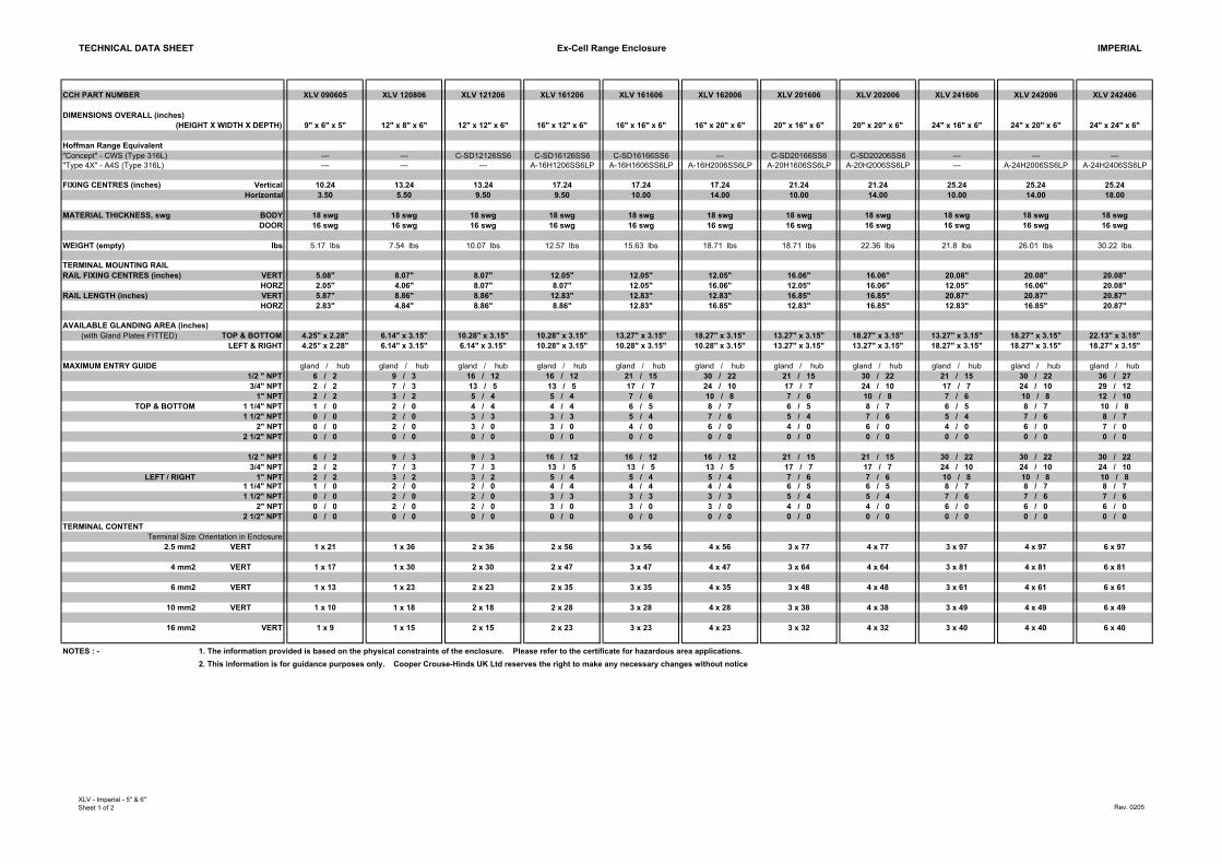
TECHNICAL DATA SHEET Ex-Cell Range Enclosure IMPERIAL
CCH PART NUMBER XLV 090605 XLV 120806 XLV 121206 XLV 161206 XLV 161606 XLV 162006 XLV 201606 XLV 202006 XLV 241606 XLV 242006 XLV 242406
DIMENSIONS OVERALL (inches)(HEIGHT X WIDTH X DEPTH) 9" x 6" x 5" 12" x 8" x 6" 12" x 12" x 6" 16" x 12" x 6" 16" x 16" x 6" 16" x 20" x 6" 20" x 16" x 6" 20" x 20" x 6" 24" x 16" x 6" 24" x 20" x 6" 24" x 24" x 6"
Hoffman Range Equivalent"Concept" - CWS (Type 316L) --- --- C-SD12126SS6 C-SD16126SS6 C-SD16166SS6 --- C-SD20166SS6 C-SD20206SS6 --- --- ---"Type 4X" - A4S (Type 316L) --- --- --- A-16H1206SS6LP A-16H1606SS6LP A-16H2006SS6LP A-20H1606SS6LP A-20H2006SS6LP --- A-24H2006SS6LP A-24H2406SS6LP
FIXING CENTRES (inches) Vertical 10.24 13.24 13.24 17.24 17.24 17.24 21.24 21.24 25.24 25.24 25.24Horizontal 3.50 5.50 9.50 9.50 10.00 14.00 10.00 14.00 10.00 14.00 18.00
MATERIAL THICKNESS, swg BODY 18 swg 18 swg 18 swg 18 swg 18 swg 18 swg 18 swg 18 swg 18 swg 18 swg 18 swgDOOR 16 swg 16 swg 16 swg 16 swg 16 swg 16 swg 16 swg 16 swg 16 swg 16 swg 16 swg
WEIGHT (empty) lbs 5.17 lbs 7.54 lbs 10.07 lbs 12.57 lbs 15.63 lbs 18.71 lbs 18.71 lbs 22.36 lbs 21.8 lbs 26.01 lbs 30.22 lbs
TERMINAL MOUNTING RAIL RAIL FIXING CENTRES (inches) VERT 5.08" 8.07" 8.07" 12.05" 12.05" 12.05" 16.06" 16.06" 20.08" 20.08" 20.08"
HORZ 2.05" 4.06" 8.07" 8.07" 12.05" 16.06" 12.05" 16.06" 12.05" 16.06" 20.08"RAIL LENGTH (inches) VERT 5.87" 8.86" 8.86" 12.83" 12.83" 12.83" 16.85" 16.85" 20.87" 20.87" 20.87"
HORZ 2.83" 4.84" 8.86" 8.86" 12.83" 16.85" 12.83" 16.85" 12.83" 16.85" 20.87"
AVAILABLE GLANDING AREA (inches) (with Gland Plates FITTED) TOP & BOTTOM 4.25" x 2.28" 6.14" x 3.15" 10.28" x 3.15" 10.28" x 3.15" 13.27" x 3.15" 18.27" x 3.15" 13.27" x 3.15" 18.27" x 3.15" 13.27" x 3.15" 18.27" x 3.15" 22.13" x 3.15"
LEFT & RIGHT 4.25" x 2.28" 6.14" x 3.15" 6.14" x 3.15" 10.28" x 3.15" 10.28" x 3.15" 10.28" x 3.15" 13.27" x 3.15" 13.27" x 3.15" 18.27" x 3.15" 18.27" x 3.15" 18.27" x 3.15"
MAXIMUM ENTRY GUIDE gland / hub gland / hub gland / hub gland / hub gland / hub gland / hub gland / hub gland / hub gland / hub gland / hub gland / hub1/2 " NPT 6 / 2 9 / 3 16 / 12 16 / 12 21 / 15 30 / 22 21 / 15 30 / 22 21 / 15 30 / 22 36 / 273/4" NPT 2 / 2 7 / 3 13 / 5 13 / 5 17 / 7 24 / 10 17 / 7 24 / 10 17 / 7 24 / 10 29 / 12
1" NPT 2 / 2 3 / 2 5 / 4 5 / 4 7 / 6 10 / 8 7 / 6 10 / 8 7 / 6 10 / 8 12 / 10TOP & BOTTOM 1 1/4" NPT 1 / 0 2 / 0 4 / 4 4 / 4 6 / 5 8 / 7 6 / 5 8 / 7 6 / 5 8 / 7 10 / 8
1 1/2" NPT 0 / 0 2 / 0 3 / 3 3 / 3 5 / 4 7 / 6 5 / 4 7 / 6 5 / 4 7 / 6 8 / 72" NPT 0 / 0 2 / 0 3 / 0 3 / 0 4 / 0 6 / 0 4 / 0 6 / 0 4 / 0 6 / 0 7 / 0
2 1/2" NPT 0 / 0 0 / 0 0 / 0 0 / 0 0 / 0 0 / 0 0 / 0 0 / 0 0 / 0 0 / 0 0 / 0
1/2 " NPT 6 / 2 9 / 3 9 / 3 16 / 12 16 / 12 16 / 12 21 / 15 21 / 15 30 / 22 30 / 22 30 / 223/4" NPT 2 / 2 7 / 3 7 / 3 13 / 5 13 / 5 13 / 5 17 / 7 17 / 7 24 / 10 24 / 10 24 / 10
LEFT / RIGHT 1" NPT 2 / 2 3 / 2 3 / 2 5 / 4 5 / 4 5 / 4 7 / 6 7 / 6 10 / 8 10 / 8 10 / 81 1/4" NPT 1 / 0 2 / 0 2 / 0 4 / 4 4 / 4 4 / 4 6 / 5 6 / 5 8 / 7 8 / 7 8 / 71 1/2" NPT 0 / 0 2 / 0 2 / 0 3 / 3 3 / 3 3 / 3 5 / 4 5 / 4 7 / 6 7 / 6 7 / 6
2" NPT 0 / 0 2 / 0 2 / 0 3 / 0 3 / 0 3 / 0 4 / 0 4 / 0 6 / 0 6 / 0 6 / 02 1/2" NPT 0 / 0 0 / 0 0 / 0 0 / 0 0 / 0 0 / 0 0 / 0 0 / 0 0 / 0 0 / 0 0 / 0
TERMINAL CONTENT Terminal Size Orientation in Enclosure
2.5 mm2 VERT 1 x 21 1 x 36 2 x 36 2 x 56 3 x 56 4 x 56 3 x 77 4 x 77 3 x 97 4 x 97 6 x 97
4 mm2 VERT 1 x 17 1 x 30 2 x 30 2 x 47 3 x 47 4 x 47 3 x 64 4 x 64 3 x 81 4 x 81 6 x 81
6 mm2 VERT 1 x 13 1 x 23 2 x 23 2 x 35 3 x 35 4 x 35 3 x 48 4 x 48 3 x 61 4 x 61 6 x 61
10 mm2 VERT 1 x 10 1 x 18 2 x 18 2 x 28 3 x 28 4 x 28 3 x 38 4 x 38 3 x 49 4 x 49 6 x 49
16 mm2 VERT 1 x 9 1 x 15 2 x 15 2 x 23 3 x 23 4 x 23 3 x 32 4 x 32 3 x 40 4 x 40 6 x 40
NOTES : - 1. The information provided is based on the physical constraints of the enclosure. Please refer to the certificate for hazardous area applications.2. This information is for guidance purposes only. Cooper Crouse-Hinds UK Ltd reserves the right to make any necessary changes without notice
XLV - Imperial - 5" & 6"Sheet 1 of 2 Rev. 0205
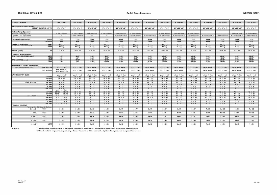
TECHNICAL DATA SHEET Ex-Cell Range Enclosures IMPERIAL (DEEP)
CCH PART NUMBER XLV 121208 XLV 161208 XLV 161608 XLV 162008 XLV 201608 XLV 202008 XLV 202408 XLV 241608 XLV 242008 XLV 242408 XLV 243008 XLV 302008 XLV 302408 XLV 303008
DIMENSIONS OVERALL (inches)(HEIGHT X WIDTH X DEPTH) 12" x 12" x 8" 16" x 12" x 8" 16" x 16" x 8" 16" x 20" x 8" 20" x 16" x 8" 20" x 20" x 8" 20" x 24" x 8" 24" x 16" x 8" 24" x 20" x 8" 24" x 24" x 8" 24" x 30" x 8" 30" x 20" x 8" 30" x 24" x 8" 30" x 30" x 8"
Hoffman Range Equivalent"Concept" - CWS (Type 316L) C-SD12126SS6 C-SD16128SS6 C-SD16168SS6 C-SD16208SS6 C-SD20168SS6 C-SD20208SS6 --- C-SD24168SS6 C-SD24208SS6 C-SD24248SS6 --- --- C-SD30248SS6 C-SD30308SS6"Type 4X" - A4S (Type 316L) --- A-16H1208SS6LP --- --- A-20H1608SS6LP A-20H2008SS6LP A-20H2408SS6LP A-24H1608SS6LP A-24H2008SS6LP A-16H2006SS6LP A-24H3008SS6LP A-30H2008SS6LP A-30H2408SS6LP A-30H3008SS6LP
FIXING CENTRES (inches) Vertical 13.24 17.24 17.24 17.24 21.24 21.24 21.24 25.24 25.24 25.24 25.24 31.24 31.24 31.24Horizontal 9.50 9.50 10.00 14.00 10.00 14.00 18.00 10.00 14.00 18.00 24.00 14.00 18.00 24.00
MATERIAL THICKNESS, swg BODY 18 swg 18 swg 18 swg 18 swg 18 swg 18 swg 18 swg 18 swg 18 swg 18 swg 18 swg 18 swg 18 swg 18 swgDOOR 16 swg 16 swg 16 swg 16 swg 16 swg 16 swg 16 swg 16 swg 16 swg 16 swg 16 swg 16 swg 16 swg 16 swg
WEIGHT (empty) lbs 12.76 lbs 14.54 lbs 17.87 lbs 21.24 lbs 21.24 lbs 25.17 lbs 29.1 lbs 24.61 lbs 29.1 lbs 33.6 lbs 40.3 lbs 34.96 lbs 40.3 lbs 48.25 lbs
TERMINAL MOUNTING RAIL RAIL FIXING CENTRES (inches) VERT 8.11" 12.05" 12.05" 12.05" 16.06" 16.06" 16.06" 20.08" 20.08" 20.08" 20.08" 26.06" 26.06" 26.06"
HORZ 8.11" 8.07" 12.05" 16.06" 12.05" 16.06" 20.08" 12.05" 16.06" 20.08" 26.06" 16.06" 20.08" 26.06"RAIL LENGTH (inches) VERT 8.90" 12.83" 12.83" 12.83" 16.85" 16.85" 16.85" 20.87" 20.87" 20.87" 20.87" 26.85" 26.85" 26.85"
HORZ 8.90" 8.86" 12.83" 16.85" 12.83" 16.85" 20.87" 12.83" 16.85" 20.87" 26.85" 16.85" 20.87" 26.85"
AVAILABLE GLANDING AREA (inches) (with Gland Plates FITTED) TOP & BOTTOM 10.27" x 4.88" 10.27" x 4.88" 13.15" x 4.88" 18.11" x 4.88" 13.15" x 4.88" 18.11" x 4.88" 22.13" x 4.88" 13.15" x 4.88" 18.11" x 4.88" 22.13" x 4.88" 28.11" x 4.88" 18.11" x 4.88" 22.13" x 4.88" 28.11" x 4.88"
LEFT & RIGHT 8.42" x 4.88" (L) 10.27" x 4.88" (R) 10.27" x 4.88" 10.27" x 4.88" 10.27" x 4.88" 13.15" x 4.88" 13.15" x 4.88" 13.15" x 4.88" 18.11" x 4.88" 18.11" x 4.88" 18.11" x 4.88" 18.11" x 4.88" 22.13" x 4.88" 22.13" x 4.88" 22.13" x 4.88"
MAXIMUM ENTRY GUIDE gland / hub gland / hub gland / hub gland / hub gland / hub gland / hub gland / hub gland / hub gland / hub gland / hub gland / hub gland / hub gland / hub gland / hub1/2 " NPT 32 / 18 32 / 18 42 / 23 58 / 33 42 / 23 58 / 33 72 / 41 42 / 23 58 / 33 72 / 41 94 / 51 58 / 33 72 / 41 94 / 513/4" NPT 20 / 10 20 / 10 26 / 13 36 / 18 26 / 13 36 / 18 44 / 23 26 / 13 36 / 18 44 / 23 57 / 30 36 / 18 44 / 23 57 / 30
1" NPT 15 / 8 15 / 8 21 / 11 30 / 16 21 / 11 30 / 16 36 / 19 21 / 11 30 / 16 36 / 19 47 / 25 30 / 16 36 / 19 47 / 25TOP & BOTTOM 1 1/4" NPT 8 / 7 8 / 7 11 / 9 15 / 13 11 / 9 15 / 13 19 / 16 11 / 9 15 / 13 19 / 16 24 / 21 15 / 13 19 / 16 24 / 21
1 1/2" NPT 6 / 3 6 / 3 9 / 4 13 / 6 9 / 4 13 / 6 16 / 7 9 / 4 13 / 6 16 / 7 20 / 9 13 / 6 16 / 7 20 / 92" NPT 3 / 3 3 / 3 4 / 3 5 / 5 4 / 3 5 / 5 7 / 6 4 / 3 5 / 5 7 / 6 9 / 8 5 / 5 7 / 6 9 / 8
2 1/2" NPT 2 / 2 2 / 2 3 / 3 4 / 4 3 / 3 4 / 4 5 / 5 3 / 3 4 / 4 5 / 5 7 / 7 4 / 4 5 / 5 7 / 7Left - Right
1/2 " NPT 26 / 14 - 32 / 18 32 / 18 32 / 18 32 / 18 42 / 23 42 / 23 42 / 23 58 / 33 58 / 33 58 / 33 58 / 33 72 / 41 72 / 41 72 / 413/4" NPT 15 / 8 - 20 / 10 20 / 10 20 / 10 20 / 10 26 / 13 26 / 13 26 / 13 36 / 18 36 / 18 36 / 18 36 / 18 44 / 23 44 / 23 44 / 23
LEFT / RIGHT 1" NPT 12 / 6 - 15 / 8 15 / 8 15 / 8 15 / 8 21 / 11 21 / 11 21 / 11 30 / 16 30 / 16 30 / 16 30 / 16 36 / 19 36 / 19 36 / 191 1/4" NPT 6 / 5 - 8 / 7 8 / 7 8 / 7 8 / 7 11 / 9 11 / 9 11 / 9 15 / 13 15 / 13 15 / 13 15 / 13 19 / 16 19 / 16 19 / 161 1/2" NPT 5 / 2 - 6 / 3 6 / 3 6 / 3 6 / 3 9 / 4 9 / 4 9 / 4 13 / 6 13 / 6 13 / 6 13 / 6 16 / 7 16 / 7 16 / 7
2" NPT 2 / 2 - 3 / 3 3 / 3 3 / 3 3 / 3 4 / 3 4 / 3 4 / 3 5 / 5 5 / 5 5 / 5 5 / 5 7 / 6 7 / 6 7 / 62 1/2" NPT 2 / 2 - 2 / 2 2 / 2 2 / 2 2 / 2 3 / 3 3 / 3 3 / 3 4 / 4 4 / 4 4 / 4 4 / 4 5 / 5 5 / 5 5 / 5
TERMINAL CONTENT Terminal Size Orientation in Enclosure
2.5 mm2 VERT 2 x 36 2 x 56 3 x 56 4 x 56 3 x 77 4 x 77 6 x 77 3 x 97 4 x 97 6 x 97 7 x 97 4 x 128 6 x 128 7 x 128
4 mm2 VERT 2 x 30 2 x 47 3 x 47 4 x 47 3 x 64 4 x 64 6 x 64 3 x 81 4 x 81 6 x 81 7 x 81 4 x 10⁶ 6 x 10⁶ 7 x 10⁶
6 mm2 VERT 2 x 23 2 x 35 3 x 35 4 x 35 3 x 48 4 x 48 6 x 48 3 x 61 4 x 61 6 x 61 7 x 61 4 x 80 6 x 80 7 x 80
10 mm2 VERT 2 x 18 2 x 28 3 x 28 4 x 28 3 x 38 4 x 38 6 x 38 3 x 49 4 x 49 6 x 49 7 x 49 4 x 64 6 x 64 7 x 64
16 mm2 VERT 2 x 15 2 x 23 3 x 23 4 x 23 3 x 32 4 x 32 6 x 32 3 x 40 4 x 40 6 x 40 7 x 40 4 x 53 6 x 53 7 x 53
NOTES : - 1. The information provided is based on the physical constraints of the enclosure. Please refer to the certificate for hazardous area applications.2. This information is for guidance purposes only. Cooper Crouse-Hinds UK Ltd reserves the right to make any necessary changes without notice
XLV - ImperialSheet 2 of 2 Rev. 0305
Refer to our website: ww
w.enclosures-crouse-hinds.uk
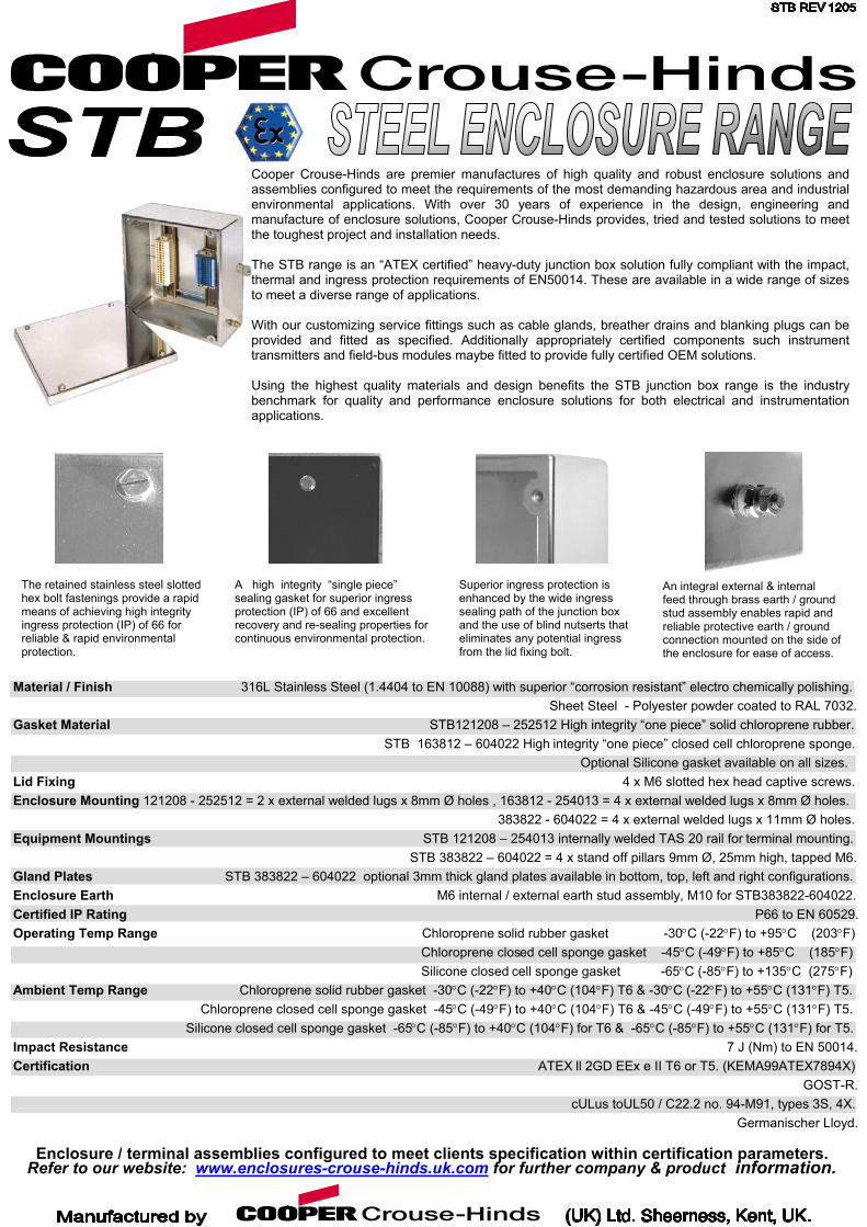
Superior ingress protection is enhanced by the wide ingress sealing path of the junction box and the use of blind nutserts that eliminates any potential ingress from the lid fixing bolt.
A high integrity “single piece” sealing gasket for superior ingress protection (IP) of 66 and excellent recovery and re-sealing properties for continuous environmental protection.
Enclosure / terminal assemblies configured to meet clients specification within certification parameters.
Material / Finish 316L Stainless Steel (1.4404 to EN 10088) with superior “corrosion resistant” electro chemically polishing. Sheet Steel - Polyester powder coated to RAL 7032. Gasket Material STB121208 – 252512 High integrity “one piece” solid chloroprene rubber. STB 163812 – 604022 High integrity “one piece” closed cell chloroprene sponge. Optional Silicone gasket available on all sizes. Lid Fixing 4 x M6 slotted hex head captive screws. Enclosure Mounting 121208 - 252512 = 2 x external welded lugs x 8mm Ø holes , 163812 - 254013 = 4 x external welded lugs x 8mm Ø holes. 383822 - 604022 = 4 x external welded lugs x 11mm Ø holes. Equipment Mountings STB 121208 – 254013 internally welded TAS 20 rail for terminal mounting. STB 383822 – 604022 = 4 x stand off pillars 9mm Ø, 25mm high, tapped M6. Gland Plates STB 383822 – 604022 optional 3mm thick gland plates available in bottom, top, left and right configurations. Enclosure Earth M6 internal / external earth stud assembly, M10 for STB383822-604022. Certified IP Rating P66 to EN 60529. Operating Temp Range Chloroprene solid rubber gasket -30°C (-22°F) to +95°C (203°F) Chloroprene closed cell sponge gasket -45°C (-49°F) to +85°C (185°F) Silicone closed cell sponge gasket -65°C (-85°F) to +135°C (275°F) Ambient Temp Range Chloroprene solid rubber gasket -30°C (-22°F) to +40°C (104°F) T6 & -30°C (-22°F) to +55°C (131°F) T5. Chloroprene closed cell sponge gasket -45°C (-49°F) to +40°C (104°F) T6 & -45°C (-49°F) to +55°C (131°F) T5. Silicone closed cell sponge gasket -65°C (-85°F) to +40°C (104°F) for T6 & -65°C (-85°F) to +55°C (131°F) for T5. Impact Resistance 7 J (Nm) to EN 50014. Certification ATEX ll 2GD EEx e II T6 or T5. (KEMA99ATEX7894X) GOST-R. cULus toUL50 / C22.2 no. 94-M91, types 3S, 4X. Germanischer Lloyd.
The retained stainless steel slotted hex bolt fastenings provide a rapid means of achieving high integrity ingress protection (IP) of 66 for reliable & rapid environmental protection.
.com for further company &
An integral external & internal feed through brass earth / ground stud assembly enables rapid and reliable protective earth / ground connection mounted on the side of the enclosure for ease of access.
Cooper Crouse-Hinds are premier manufactures of high quality and robust enclosure solutions andassemblies configured to meet the requirements of the most demanding hazardous area and industrialenvironmental applications. With over 30 years of experience in the design, engineering andmanufacture of enclosure solutions, Cooper Crouse-Hinds provides, tried and tested solutions to meetthe toughest project and installation needs. The STB range is an “ATEX certified” heavy-duty junction box solution fully compliant with the impact,thermal and ingress protection requirements of EN50014. These are available in a wide range of sizesto meet a diverse range of applications. With our customizing service fittings such as cable glands, breather drains and blanking plugs can beprovided and fitted as specified. Additionally appropriately certified components such instrumenttransmitters and field-bus modules maybe fitted to provide fully certified OEM solutions. Using the highest quality materials and design benefits the STB junction box range is the industrybenchmark for quality and performance enclosure solutions for both electrical and instrumentationapplications.
prod
uct information.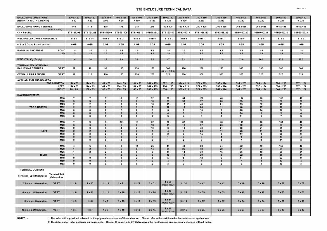
STB ENCLOSURE TECHNICAL DATA REV. 0205
ENCLOSURE DIMENTIONS 120 x 120 150 x 120 150 x 150 190 x 150 190 x 190 250 x 250 160 x 380 250 x 400 380 x 380 380 x 380 400 x 600 400 x 600 600 x 400 600 x 400(HEIGHT X WIDTH X DEPTH) x 80 x 80 x 90 x 90 x 100 x 120 x 120 x 130 x 220 x 220 x 220 x 220 x 220 x 220
ENCLOSURE FIXING CENTRES 145 175 175 175 215 275 80 x 405 150 x 425 250 x 435 250 x 435 264 x 656 264 x 656 464 x 456 464 x 456(Vert x Horiz)
CCH Part No. STB121208 STB151208 STB151509 STB191509 STB191910 STB252512 STB163812 STB254013 STB3838220 STB3838223 STB4060220 STB4060223 STB6040220 STB6040223
WEIDMULLER CROSS REFERENCE STB 1 STB 1-1 STB 2 STB 2-1 STB 3 STB 4 STB 5 STB 6 STB 7 STB 7 STB 8 STB 8 STB 9 STB 9
0, 1 or 3 Gland Plated Version 0 GP 0 GP 0 GP 0 GP 0 GP 0 GP 0 GP 0 GP 0 GP 3 GP 0 GP 3 GP 0 GP 3 GP
MATERIAL THICKNESS BODY 1.5 1.5 1.5 1.5 1.5 1.5 1.5 1.5 1.5 1.5 1.5 1.5 1.5 1.5LID 1.5 1.5 1.5 1.5 1.5 1.5 1.5 1.5 1.5 1.5 1.5 1.5 1.5 1.5
WEIGHT in Kg (Empty) 1.4 1.6 1.9 2.3 3.0 3.7 3.7 5.4 8.5 11.8 13.0 16.5 13.0 16.5
TERMINAL MOUNTING RAIL RAIL FIXING CENTRES VERT 62 90 90 130 130 180 300 180 280 280 300 300 500 500
(Horiz. CRS)OVERALL RAIL LENGTH VERT 82 110 110 150 150 200 320 200 300 300 320 320 520 520
AVAILABLE GLANDING AREA TOP & BOTTOM 114 x 63 114 x 63 144 x 73 144 x 73 184 x 83 244 x 103 372 x 103 394 x 113 374 x 203 337 x 124 594 x 203 504 x 124 394 x 203 337 x 124
LEFT 114 x 63 144 x 63 144 x 73 184 x 73 184 x 83 244 x 103 154 x 103 244 x 113 374 x 203 337 x 124 394 x 203 337 x 124 594 x 203 337 x 124RIGHT 70 x 63 100 x 63 100 x 73 130 x 73 140 x 83 200 x 103 330 x 103 350 x 113 324 x 203 261 x 124 344 x 203 304 x 124 544 x 203 337 x 124
MAXIMUM ENTRIESM16 7 7 9 9 18 32 50 54 100 46 164 70 108 46M20 3 3 6 6 8 18 29 30 57 26 93 39 60 26M25 2 2 3 3 7 10 15 16 40 21 65 32 40 21
TOP & BOTTOM M32 2 2 2 2 3 7 12 13 24 11 40 17 26 11M40 0 0 2 2 2 3 5 6 15 9 26 14 17 9M50 0 0 0 0 2 3 4 5 8 4 14 6 9 4M63 0 0 0 0 0 2 3 4 6 3 11 5 7 3
M16 7 9 9 12 18 32 20 32 100 46 108 46 164 46M20 3 3 6 8 8 18 11 18 57 26 60 26 93 26M25 2 3 3 4 7 10 6 10 40 21 40 21 65 21
LEFT M32 2 2 2 3 3 7 4 7 24 11 26 11 40 11M40 0 0 2 2 2 3 2 3 15 9 17 9 26 9M50 0 0 0 0 2 3 1 3 8 4 9 4 14 4M63 0 0 0 0 0 2 1 2 6 3 7 3 11 3
M16 4 6 6 8 14 26 44 48 88 34 92 40 152 46M20 1 2 4 6 6 14 24 26 48 20 51 23 84 26M25 1 2 2 2 5 8 14 14 33 15 35 18 60 21
RIGHT M32 1 1 1 2 2 6 10 11 20 8 22 10 38 11M40 0 0 1 1 2 3 5 5 12 6 14 8 23 9M50 0 0 0 0 1 2 4 4 7 3 7 3 13 4M63 0 0 0 0 0 2 3 3 5 2 6 3 10 3
TERMINAL CONTENT
Terminal Type (thickness) Terminal Rail Orientation
2.5mm sq. (6mm wide) VERT 1 x 8 1 x 13 1 x 13 1 x 21 1 x 21 2 x 31 1 x 55 (Horiz. Row) 3 x 31 3 x 42 3 x 42 3 x 46 3 x 46 5 x 79 5 x 79
4mm sq. (6.5mm wide) VERT 1 x 6 1 x 11 1 x 11 1 x 18 1 x 18 2 x 26 1 x 46 (Horiz. Row) 3 x 26 3 x 39 3 x 39 3 x 42 3 x 42 5 x 73 5 x 73
6mm sq. (8mm wide) VERT 1 x 5 1 x 8 1 x 8 1 x 13 1 x 13 2 x 19 1 x 34 (Horiz. Row) 3 x 19 3 x 32 3 x 32 3 x 34 3 x 34 5 x 59 5 x 59
10mm sq. (10mm wide) VERT 1 x 4 1 x 7 1 x 7 1 x 10 1 x 10 2 x 15 1 x 28 (Horiz. Row) 3 x 15 3 x 25 3 x 25 3 x 27 3 x 27 5 x 47 5 x 47
NOTES : - 1. The information provided is based on the physical constraints of the enclosure. Please refer to the certificate for hazardous area applications.2. This information is for guidance purposes only. Cooper Crouse-Hinds UK Ltd reserves the right to make any necessary changes without notice
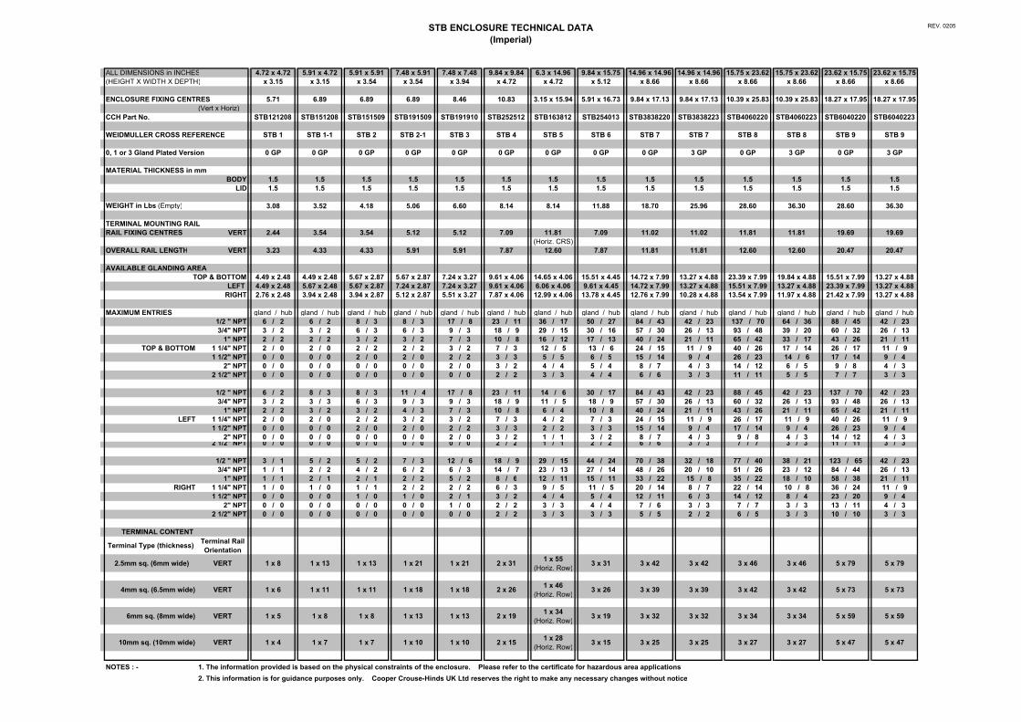
STB ENCLOSURE TECHNICAL DATA(Imperial)
REV. 0205
ALL DIMENSIONS in INCHES 4.72 x 4.72 5.91 x 4.72 5.91 x 5.91 7.48 x 5.91 7.48 x 7.48 9.84 x 9.84 6.3 x 14.96 9.84 x 15.75 14.96 x 14.96 14.96 x 14.96 15.75 x 23.62 15.75 x 23.62 23.62 x 15.75 23.62 x 15.75(HEIGHT X WIDTH X DEPTH) x 3.15 x 3.15 x 3.54 x 3.54 x 3.94 x 4.72 x 4.72 x 5.12 x 8.66 x 8.66 x 8.66 x 8.66 x 8.66 x 8.66
ENCLOSURE FIXING CENTRES 5.71 6.89 6.89 6.89 8.46 10.83 3.15 x 15.94 5.91 x 16.73 9.84 x 17.13 9.84 x 17.13 10.39 x 25.83 10.39 x 25.83 18.27 x 17.95 18.27 x 17.95(Vert x Horiz)
CCH Part No. STB121208 STB151208 STB151509 STB191509 STB191910 STB252512 STB163812 STB254013 STB3838220 STB3838223 STB4060220 STB4060223 STB6040220 STB6040223
WEIDMULLER CROSS REFERENCE STB 1 STB 1-1 STB 2 STB 2-1 STB 3 STB 4 STB 5 STB 6 STB 7 STB 7 STB 8 STB 8 STB 9 STB 9
0, 1 or 3 Gland Plated Version 0 GP 0 GP 0 GP 0 GP 0 GP 0 GP 0 GP 0 GP 0 GP 3 GP 0 GP 3 GP 0 GP 3 GP
MATERIAL THICKNESS in mmBODY 1.5 1.5 1.5 1.5 1.5 1.5 1.5 1.5 1.5 1.5 1.5 1.5 1.5 1.5
LID 1.5 1.5 1.5 1.5 1.5 1.5 1.5 1.5 1.5 1.5 1.5 1.5 1.5 1.5
WEIGHT in Lbs (Empty) 3.08 3.52 4.18 5.06 6.60 8.14 8.14 11.88 18.70 25.96 28.60 36.30 28.60 36.30
TERMINAL MOUNTING RAIL RAIL FIXING CENTRES VERT 2.44 3.54 3.54 5.12 5.12 7.09 11.81 7.09 11.02 11.02 11.81 11.81 19.69 19.69
(Horiz. CRS)OVERALL RAIL LENGTH VERT 3.23 4.33 4.33 5.91 5.91 7.87 12.60 7.87 11.81 11.81 12.60 12.60 20.47 20.47
AVAILABLE GLANDING AREA TOP & BOTTOM 4.49 x 2.48 4.49 x 2.48 5.67 x 2.87 5.67 x 2.87 7.24 x 3.27 9.61 x 4.06 14.65 x 4.06 15.51 x 4.45 14.72 x 7.99 13.27 x 4.88 23.39 x 7.99 19.84 x 4.88 15.51 x 7.99 13.27 x 4.88
LEFT 4.49 x 2.48 5.67 x 2.48 5.67 x 2.87 7.24 x 2.87 7.24 x 3.27 9.61 x 4.06 6.06 x 4.06 9.61 x 4.45 14.72 x 7.99 13.27 x 4.88 15.51 x 7.99 13.27 x 4.88 23.39 x 7.99 13.27 x 4.88RIGHT 2.76 x 2.48 3.94 x 2.48 3.94 x 2.87 5.12 x 2.87 5.51 x 3.27 7.87 x 4.06 12.99 x 4.06 13.78 x 4.45 12.76 x 7.99 10.28 x 4.88 13.54 x 7.99 11.97 x 4.88 21.42 x 7.99 13.27 x 4.88
MAXIMUM ENTRIES gland / hub gland / hub gland / hub gland / hub gland / hub gland / hub gland / hub gland / hub gland / hub gland / hub gland / hub gland / hub gland / hub gland / hub1/2 " NPT 6 / 2 6 / 2 8 / 3 8 / 3 17 / 8 23 / 11 36 / 17 50 / 27 84 / 43 42 / 23 137 / 70 64 / 36 88 / 45 42 / 233/4" NPT 3 / 2 3 / 2 6 / 3 6 / 3 9 / 3 18 / 9 29 / 15 30 / 16 57 / 30 26 / 13 93 / 48 39 / 20 60 / 32 26 / 13
1" NPT 2 / 2 2 / 2 3 / 2 3 / 2 7 / 3 10 / 8 16 / 12 17 / 13 40 / 24 21 / 11 65 / 42 33 / 17 43 / 26 21 / 11TOP & BOTTOM 1 1/4" NPT 2 / 0 2 / 0 2 / 2 2 / 2 3 / 2 7 / 3 12 / 5 13 / 6 24 / 15 11 / 9 40 / 26 17 / 14 26 / 17 11 / 9
1 1/2" NPT 0 / 0 0 / 0 2 / 0 2 / 0 2 / 2 3 / 3 5 / 5 6 / 5 15 / 14 9 / 4 26 / 23 14 / 6 17 / 14 9 / 42" NPT 0 / 0 0 / 0 0 / 0 0 / 0 2 / 0 3 / 2 4 / 4 5 / 4 8 / 7 4 / 3 14 / 12 6 / 5 9 / 8 4 / 3
2 1/2" NPT 0 / 0 0 / 0 0 / 0 0 / 0 0 / 0 2 / 2 3 / 3 4 / 4 6 / 6 3 / 3 11 / 11 5 / 5 7 / 7 3 / 3
1/2 " NPT 6 / 2 8 / 3 8 / 3 11 / 4 17 / 8 23 / 11 14 / 6 30 / 17 84 / 43 42 / 23 88 / 45 42 / 23 137 / 70 42 / 233/4" NPT 3 / 2 3 / 3 6 / 3 9 / 3 9 / 3 18 / 9 11 / 5 18 / 9 57 / 30 26 / 13 60 / 32 26 / 13 93 / 48 26 / 13
1" NPT 2 / 2 3 / 2 3 / 2 4 / 3 7 / 3 10 / 8 6 / 4 10 / 8 40 / 24 21 / 11 43 / 26 21 / 11 65 / 42 21 / 11LEFT 1 1/4" NPT 2 / 0 2 / 0 2 / 2 3 / 2 3 / 2 7 / 3 4 / 2 7 / 3 24 / 15 11 / 9 26 / 17 11 / 9 40 / 26 11 / 9
1 1/2" NPT 0 / 0 0 / 0 2 / 0 2 / 0 2 / 2 3 / 3 2 / 2 3 / 3 15 / 14 9 / 4 17 / 14 9 / 4 26 / 23 9 / 42" NPT 0 / 0 0 / 0 0 / 0 0 / 0 2 / 0 3 / 2 1 / 1 3 / 2 8 / 7 4 / 3 9 / 8 4 / 3 14 / 12 4 / 3
2 1/2" NPT 0 / 0 0 / 0 0 / 0 0 / 0 0 / 0 2 / 2 1 / 1 2 / 2 6 / 6 3 / 3 7 / 7 3 / 3 11 / 11 3 / 3
1/2 " NPT 3 / 1 5 / 2 5 / 2 7 / 3 12 / 6 18 / 9 29 / 15 44 / 24 70 / 38 32 / 18 77 / 40 38 / 21 123 / 65 42 / 233/4" NPT 1 / 1 2 / 2 4 / 2 6 / 2 6 / 3 14 / 7 23 / 13 27 / 14 48 / 26 20 / 10 51 / 26 23 / 12 84 / 44 26 / 13
1" NPT 1 / 1 2 / 1 2 / 1 2 / 2 5 / 2 8 / 6 12 / 11 15 / 11 33 / 22 15 / 8 35 / 22 18 / 10 58 / 38 21 / 11RIGHT 1 1/4" NPT 1 / 0 1 / 0 1 / 1 2 / 2 2 / 2 6 / 3 9 / 5 11 / 5 20 / 14 8 / 7 22 / 14 10 / 8 36 / 24 11 / 9
1 1/2" NPT 0 / 0 0 / 0 1 / 0 1 / 0 2 / 1 3 / 2 4 / 4 5 / 4 12 / 11 6 / 3 14 / 12 8 / 4 23 / 20 9 / 42" NPT 0 / 0 0 / 0 0 / 0 0 / 0 1 / 0 2 / 2 3 / 3 4 / 4 7 / 6 3 / 3 7 / 7 3 / 3 13 / 11 4 / 3
2 1/2" NPT 0 / 0 0 / 0 0 / 0 0 / 0 0 / 0 2 / 2 3 / 3 3 / 3 5 / 5 2 / 2 6 / 5 3 / 3 10 / 10 3 / 3
TERMINAL CONTENT
Terminal Type (thickness) Terminal Rail Orientation
2.5mm sq. (6mm wide) VERT 1 x 8 1 x 13 1 x 13 1 x 21 1 x 21 2 x 31 1 x 55 (Horiz. Row)
3 x 31 3 x 42 3 x 42 3 x 46 3 x 46 5 x 79 5 x 79
4mm sq. (6.5mm wide) VERT 1 x 6 1 x 11 1 x 11 1 x 18 1 x 18 2 x 26 1 x 46 (Horiz. Row)
3 x 26 3 x 39 3 x 39 3 x 42 3 x 42 5 x 73 5 x 73
6mm sq. (8mm wide) VERT 1 x 5 1 x 8 1 x 8 1 x 13 1 x 13 2 x 19 1 x 34 (Horiz. Row)
3 x 19 3 x 32 3 x 32 3 x 34 3 x 34 5 x 59 5 x 59
10mm sq. (10mm wide) VERT 1 x 4 1 x 7 1 x 7 1 x 10 1 x 10 2 x 15 1 x 28 (Horiz. Row)
3 x 15 3 x 25 3 x 25 3 x 27 3 x 27 5 x 47 5 x 47
NOTES : - 1. The information provided is based on the physical constraints of the enclosure. Please refer to the certificate for hazardous area applications.2. This information is for guidance purposes only. Cooper Crouse-Hinds UK Ltd reserves the right to make any necessary changes without notice
Refer to our website: www
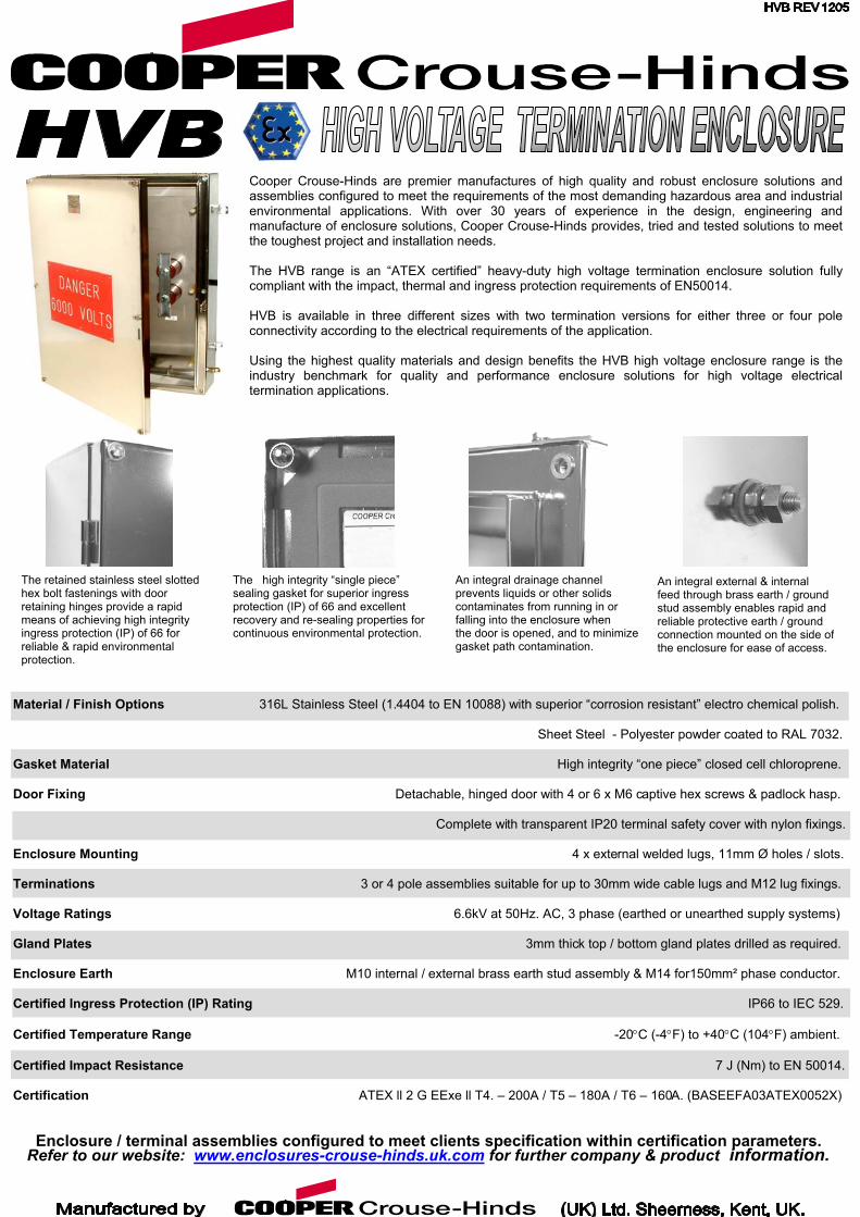
Cooper Crouse-Hinds are premier manufactures of high quality and robust enclosure solutions andassemblies configured to meet the requirements of the most demanding hazardous area and industrialenvironmental applications. With over 30 years of experience in the design, engineering andmanufacture of enclosure solutions, Cooper Crouse-Hinds provides, tried and tested solutions to meetthe toughest project and installation needs. The HVB range is an “ATEX certified” heavy-duty high voltage termination enclosure solution fullycompliant with the impact, thermal and ingress protection requirements of EN50014. HVB is available in three different sizes with two termination versions for either three or four poleconnectivity according to the electrical requirements of the application. Using the highest quality materials and design benefits the HVB high voltage enclosure range is theindustry benchmark for quality and performance enclosure solutions for high voltage electricaltermination applications.
An integral drainage channel prevents liquids or other solids contaminates from running in or falling into the enclosure when the door is opened, and to minimize
The high integrity “single piece” sealing gasket for superior ingress protection (IP) of 66 and excellent recovery and re-sealing properties for continuous environmental protection.
gasket path contamination.
Enclosure / terminal assemblies configured to meet clients specification within certification parameters.
Material / Finish Options 316L Stainless Steel (1.4404 to EN 10088) with superior “corrosion resistant” electro chemical polish.
Sheet Steel - Polyester powder coated to RAL 7032.
Gasket Material High integrity “one piece” closed cell chloroprene.
Door Fixing Detachable, hinged door with 4 or 6 x M6 captive hex screws & padlock hasp.
Complete with transparent IP20 terminal safety cover with nylon fixings.
Enclosure Mounting 4 x external welded lugs, 11mm Ø holes / slots.
Terminations 3 or 4 pole assemblies suitable for up to 30mm wide cable lugs and M12 lug fixings.
Voltage Ratings 6.6kV at 50Hz. AC, 3 phase (earthed or unearthed supply systems)
Gland Plates 3mm thick top / bottom gland plates drilled as required.
Enclosure Earth M10 internal / external brass earth stud assembly & M14 for150mm² phase conductor.
Certified Ingress Protection (IP) Rating IP66 to IEC 529.
Certified Temperature Range -20°C (-4°F) to +40°C (104°F) ambient.
Certified Impact Resistance 7 J (Nm) to EN 50014.
Certification ATEX ll 2 G EExe ll T4. – 200A / T5 – 180A / T6 – 160A. (BASEEFA03ATEX0052X)
The retained stainless steel slotted hex bolt fastenings with door retaining hinges provide a rapid means of achieving high integrity ingress protection (IP) of 66 for reliable & rapid environmental protection.
.enclosures-crouse-hinds.uk.com for further company &
An integral external & internal feed through brass earth / ground stud assembly enables rapid and reliable protective earth / ground connection mounted on the side of the enclosure for ease of access.
pr
oduct information.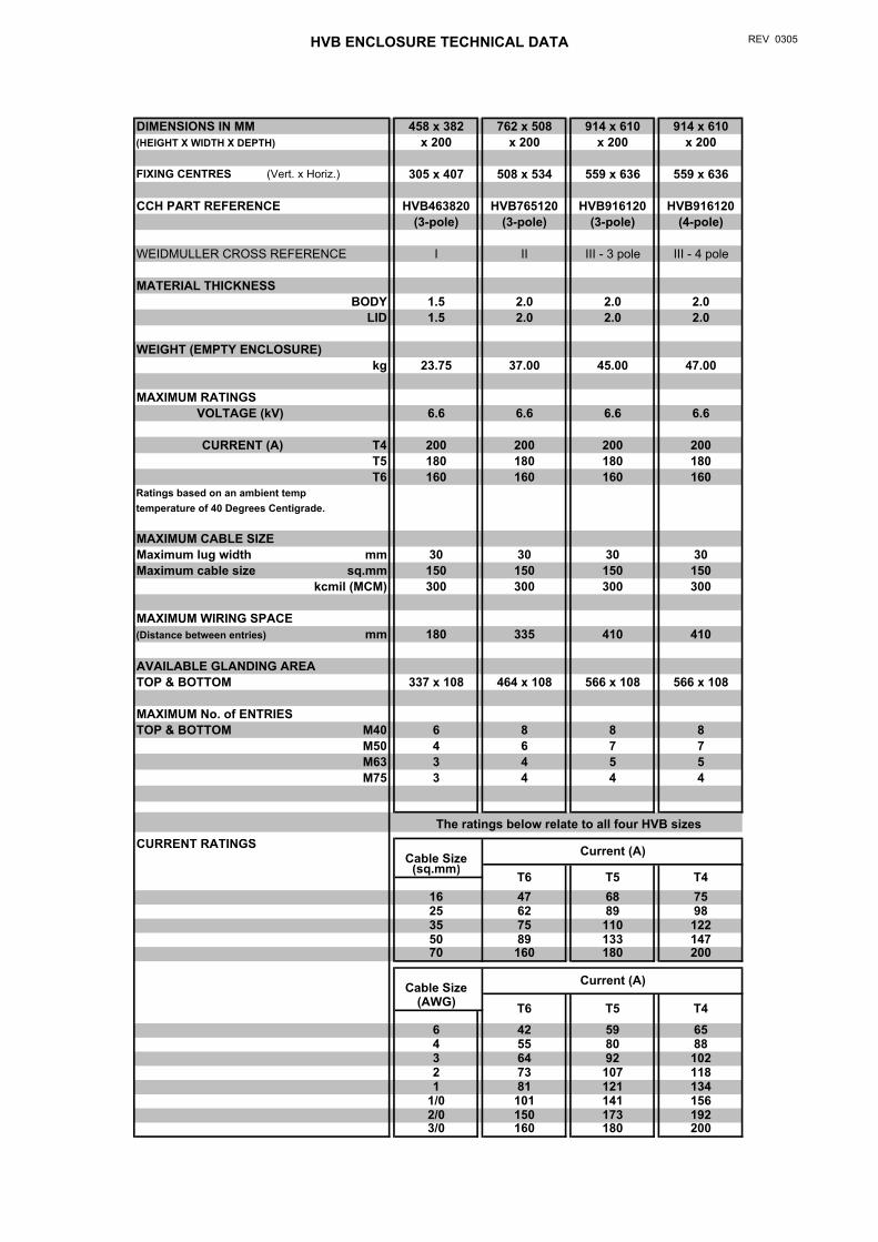
HVB ENCLOSURE TECHNICAL DATA REV 0305
DIMENSIONS IN MM 458 x 382 762 x 508 914 x 610 914 x 610(HEIGHT X WIDTH X DEPTH) x 200 x 200 x 200 x 200
FIXING CENTRES (Vert. x Horiz.) 305 x 407 508 x 534 559 x 636 559 x 636
CCH PART REFERENCE HVB463820 HVB765120 HVB916120 HVB916120(3-pole) (3-pole) (3-pole) (4-pole)
WEIDMULLER CROSS REFERENCE I II III - 3 pole III - 4 pole
MATERIAL THICKNESS BODY 1.5 2.0 2.0 2.0
LID 1.5 2.0 2.0 2.0
WEIGHT (EMPTY ENCLOSURE) kg 23.75 37.00 45.00 47.00
MAXIMUM RATINGSVOLTAGE (kV) 6.6 6.6 6.6 6.6
CURRENT (A) T4 200 200 200 200T5 180 180 180 180T6 160 160 160 160
Ratings based on an ambient temp temperature of 40 Degrees Centigrade.
MAXIMUM CABLE SIZEMaximum lug width mm 30 30 30 30Maximum cable size sq.mm 150 150 150 150
kcmil (MCM) 300 300 300 300
MAXIMUM WIRING SPACE(Distance between entries) mm 180 335 410 410
AVAILABLE GLANDING AREA TOP & BOTTOM 337 x 108 464 x 108 566 x 108 566 x 108
MAXIMUM No. of ENTRIESTOP & BOTTOM M40 6 8 8 8
M50 4 6 7 7M63 3 4 5 5M75 3 4 4 4
CURRENT RATINGSCable Size
(sq.mm)
16 47 68 7525 62 89 9835 75 110 12250 89 133 14770 160 180 200
Cable Size(AWG)
6 42 59 654 55 80 883 64 92 1022 73 107 1181 81 121 134
1/0 101 141 1562/0 150 173 1923/0 160 180 200
T6 T5 T4
Current (A)
T6 T5 T4
Current (A)
The ratings below relate to all four HVB sizes
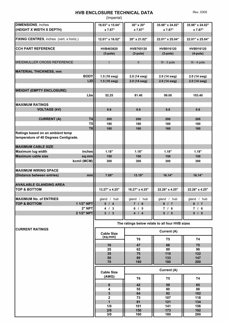
HVB ENCLOSURE TECHNICAL DATA(Imperial)
Rev. 0305
DIMENSIONS, inches 18.03" x 15.04" 30" x 20" 35.98" x 24.02" 35.98" x 24.02"(HEIGHT X WIDTH X DEPTH) x 7.87" x 7.87" x 7.87" x 7.87"
FIXING CENTRES, inches (vert. x horiz.) 12.01" x 16.02" 20" x 21.02" 22.01" x 25.04" 22.01" x 25.04"
CCH PART REFERENCE HVB463820 HVB765120 HVB916120 HVB916120(3-pole) (3-pole) (3-pole) (4-pole)
WEIDMULLER CROSS REFERENCE I II III - 3 pole III - 4 pole
MATERIAL THICKNESS, mmBODY 1.5 (16 swg) 2.0 (14 swg) 2.0 (14 swg) 2.0 (14 swg)
LID 1.5 (16 swg) 2.0 (14 swg) 2.0 (14 swg) 2.0 (14 swg)
WEIGHT (EMPTY ENCLOSURE) Lbs 52.25 81.40 99.00 103.40
MAXIMUM RATINGSVOLTAGE (kV) 6.6 6.6 6.6 6.6
CURRENT (A) T4 200 200 200 200T5 180 180 180 180T6 160 160 160 160
Ratings based on an ambient temp temperature of 40 Degrees Centigrade.
MAXIMUM CABLE SIZEMaximum lug width inches 1.18" 1.18" 1.18" 1.18"Maximum cable size sq.mm 150 150 150 150
kcmil (MCM) 300 300 300 300
MAXIMUM WIRING SPACE(Distance between entries) mm 7.09" 13.19" 16.14" 16.14"
AVAILABLE GLANDING AREA TOP & BOTTOM 13.27" x 4.25" 18.27" x 4.25" 22.28" x 4.25" 22.28" x 4.25"
MAXIMUM No. of ENTRIES gland / hub gland / hub gland / hub gland / hubTOP & BOTTOM 1 1/2" NPT 5 / 4 7 / 6 8 / 7 8 / 7
2" NPT 4 / 3 6 / 5 7 / 6 7 / 62 1/2" NPT 3 / 3 4 / 4 5 / 5 5 / 5
CURRENT RATINGSCable Size(sq.mm)
16 47 68 7525 62 89 9835 75 110 12250 89 133 14770 160 180 200
Cable Size(AWG)
6 42 59 654 55 80 883 64 92 1022 73 107 1181 81 121 134
1/0 101 141 1562/0 150 173 1923/0 160 180 200
Current (A)
T6 T5 T4
The ratings below relate to all four HVB sizes
Current (A)
T6 T5 T4
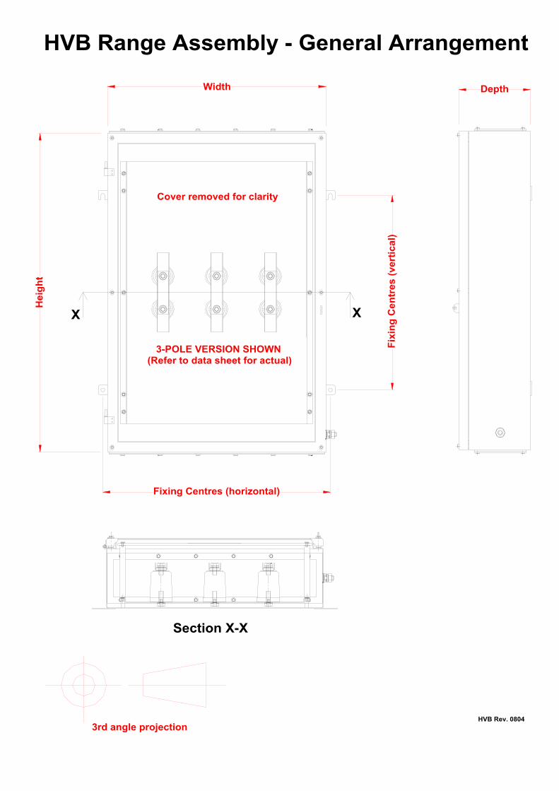
XX
Section X-X
Width
Hei
gh
t
Fixing Centres (horizontal)
Fix
ing
Cen
tres
(ve
rtic
al)
Depth
Cover removed for clarity
3-POLE VERSION SHOWN(Refer to data sheet for actual)
3rd angle projection
HVB Range Assembly - General Arrangement
HVB Rev. 0804
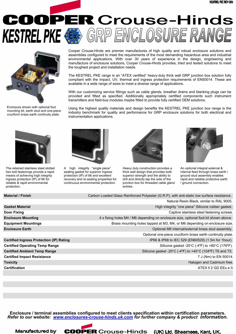
Material / Finish Gasket Material Door Fixing Enclosure Mounting Equipment Mountings Enclosure Earth Certified Ingress Protection (IP) Certified Operating Temp RangeCertified Ambient Temp Range Certified Impact Resistance Toxicity Certification
Enclosure / terminal assRefer to our website: ww
Heavy duty construction provides a thick wall design that provides both superior strength and the ability to drill and directly tap the side of the junction box for threaded cable gland entries.
An optional integral external & internal feed through brass earth / ground stud assembly enables rapid and reliable protective earth / ground connection.
The retained stainless steel slotted hex bolt fastenings provide a rapid means of achieving high integrity ingress protection (IP) of 66 for reliable & rapid environmental protection.
Ratin
emw.e
Cooper Crouse-Hinds are premier manufactures of high quality and robust enclosure solutions andassemblies configured to meet the requirements of the most demanding hazardous area and industrialenvironmental applications. With over 30 years of experience in the design, engineering andmanufacture of enclosure solutions, Cooper Crouse-Hinds provides, tried and tested solutions to meetthe toughest project and installation needs. The KESTREL PKE range is an “ATEX certified” heavy-duty thick wall GRP junction box solution fullycompliant with the impact, UV, thermal and ingress protection requirements of EN50014. These areavailable in a wide range of sizes to meet a diverse range of applications. With our customizing service fittings such as cable glands, breather drains and blanking plugs can beprovided and fitted as specified. Additionally appropriately certified components such instrumenttransmitters and field-bus modules maybe fitted to provide fully certified OEM solutions. Using the highest quality materials and design benefits the KESTREL PKE junction box range is theindustry benchmark for quality and performance for GRP enclosure solutions for both electrical andinstrumentation applications.
g
bln
Carbon Loaded G 4 x fixing h Bra
ies configured to meetclosures-crouse-hinds
Enclosure shown with optional foot mounting kit, earth stud and one-piece cruciform brass earth continuity plate.
A high integrity “single piece”
sealing gasket for superior ingress protection (IP) of 66 and excellent recovery and re-sealing properties for continuous environmental protection.
lass Reinforced Polyester (G.R.P), with anti-static low surface resistance. Natural Resin Black, similar to RAL 9005. High integrity “one piece” Silicone rubber gasket. Captive stainless steel fastening screws. oles M4 / M6 depending on enclosure size, optional foot kit shown above. ss mounting holes tapped at M3, M4, or M6 depending on enclosure size. Optional M6 internal/external brass stud assembly. Optional one-piece cruciform brass earth continuity plate. IP66 & IP68 to IEC 529 (EN60529) (1.5m for 1hour). Silicone gasket -20°C (-4ºF) to +80°C (176ºF). Silicone gasket -20°C (-4ºF) to +40°C (104ºF) T6 and T5. 7 J (Nm) to EN 50014. Halogen and Cadmium free. ATEX ll 2 GD EEx e II.
clients specification within certification parameters. .uk.com for further company & product information.
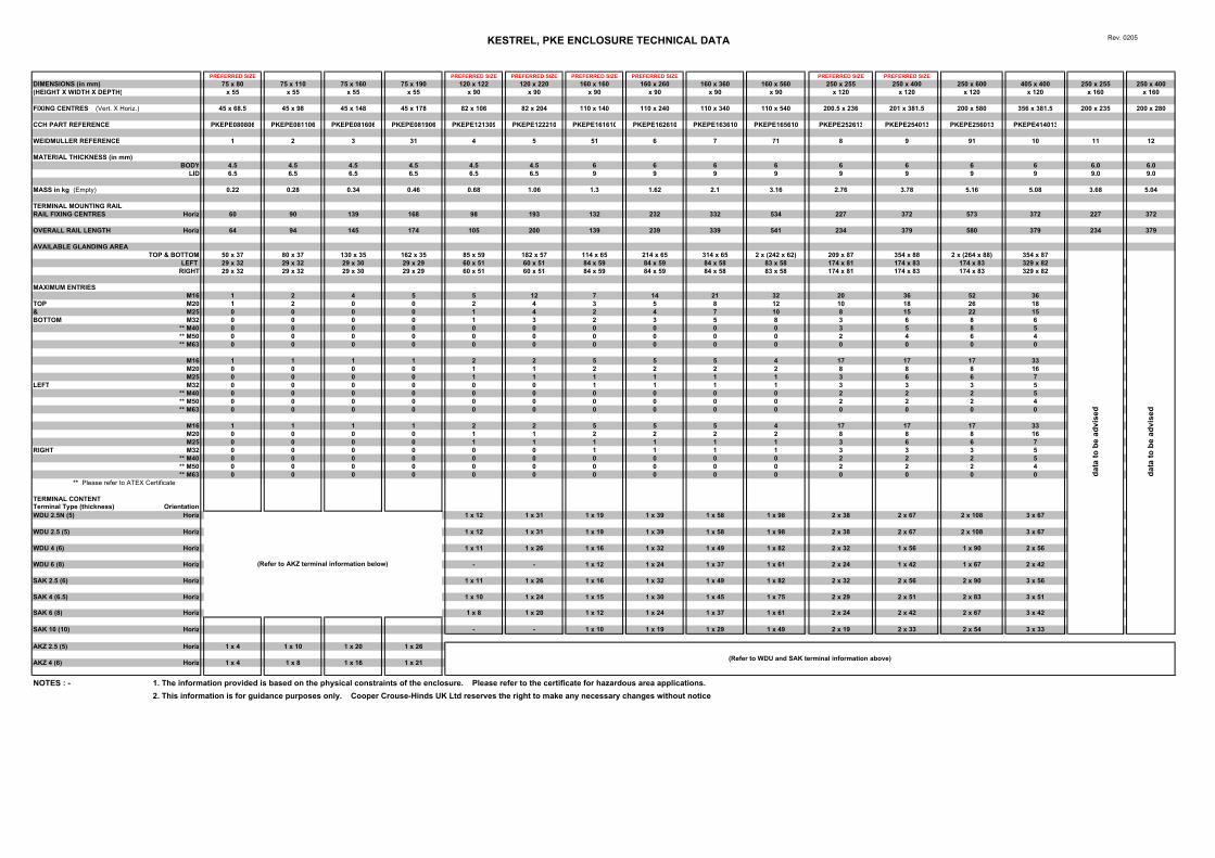
KESTREL, PKE ENCLOSURE TECHNICAL DATA Rev. 0205
PREFERRED SIZE PREFERRED SIZE PREFERRED SIZE PREFERRED SIZE PREFERRED SIZE PREFERRED SIZE PREFERRED SIZEDIMENSIONS (in mm) 75 x 80 75 x 110 75 x 160 75 x 190 120 x 122 120 x 220 160 x 160 160 x 260 160 x 360 160 x 560 250 x 255 250 x 400 250 x 600 405 x 400 250 x 255 250 x 400(HEIGHT X WIDTH X DEPTH) x 55 x 55 x 55 x 55 x 90 x 90 x 90 x 90 x 90 x 90 x 120 x 120 x 120 x 120 x 160 x 160
FIXING CENTRES (Vert. X Horiz.) 45 x 68.5 45 x 98 45 x 148 45 x 178 82 x 106 82 x 204 110 x 140 110 x 240 110 x 340 110 x 540 200.5 x 236 201 x 381.5 200 x 580 356 x 381.5 200 x 235 200 x 280
CCH PART REFERENCE PKEPE080806 PKEPE081106 PKEPE081606 PKEPE081906 PKEPE121309 PKEPE122210 PKEPE161610 PKEPE162610 PKEPE163610 PKEPE165610 PKEPE252613 PKEPE254013 PKEPE256013 PKEPE414013
WEIDMULLER REFERENCE 1 2 3 31 4 5 51 6 7 71 8 9 91 10 11 12
MATERIAL THICKNESS (in mm)BODY 4.5 4.5 4.5 4.5 4.5 4.5 6 6 6 6 6 6 6 6 6.0 6.0
LID 6.5 6.5 6.5 6.5 6.5 6.5 9 9 9 9 9 9 9 9 9.0 9.0
MASS in kg (Empty) 0.22 0.28 0.34 0.46 0.68 1.06 1.3 1.62 2.1 3.16 2.76 3.78 5.16 5.08 3.68 5.04
TERMINAL MOUNTING RAIL RAIL FIXING CENTRES Horiz 60 90 139 168 98 193 132 232 332 534 227 372 573 372 227 372
OVERALL RAIL LENGTH Horiz 64 94 145 174 105 200 139 239 339 541 234 379 580 379 234 379
AVAILABLE GLANDING AREA TOP & BOTTOM 50 x 37 80 x 37 130 x 35 162 x 35 85 x 59 182 x 57 114 x 65 214 x 65 314 x 65 2 x (242 x 62) 209 x 87 354 x 88 2 x (264 x 88) 354 x 87
LEFT 29 x 32 29 x 32 29 x 30 29 x 29 60 x 51 60 x 51 84 x 59 84 x 59 84 x 58 83 x 58 174 x 81 174 x 83 174 x 83 329 x 82RIGHT 29 x 32 29 x 32 29 x 30 29 x 29 60 x 51 60 x 51 84 x 59 84 x 59 84 x 58 83 x 58 174 x 81 174 x 83 174 x 83 329 x 82
MAXIMUM ENTRIESM16 1 2 4 5 5 12 7 14 21 32 20 36 52 36
TOP M20 1 2 0 0 2 4 3 5 8 12 10 18 26 18& M25 0 0 0 0 1 4 2 4 7 10 8 15 22 15BOTTOM M32 0 0 0 0 1 3 2 3 5 8 3 6 8 6
** M40 0 0 0 0 0 0 0 0 0 0 3 5 8 5** M50 0 0 0 0 0 0 0 0 0 0 2 4 6 4** M63 0 0 0 0 0 0 0 0 0 0 0 0 0 0
M16 1 1 1 1 2 2 5 5 5 4 17 17 17 33M20 0 0 0 0 1 1 2 2 2 2 8 8 8 16M25 0 0 0 0 1 1 1 1 1 1 3 6 6 7
LEFT M32 0 0 0 0 0 0 1 1 1 1 3 3 3 5** M40 0 0 0 0 0 0 0 0 0 0 2 2 2 5** M50 0 0 0 0 0 0 0 0 0 0 2 2 2 4** M63 0 0 0 0 0 0 0 0 0 0 0 0 0 0
M16 1 1 1 1 2 2 5 5 5 4 17 17 17 33M20 0 0 0 0 1 1 2 2 2 2 8 8 8 16M25 0 0 0 0 1 1 1 1 1 1 3 6 6 7
RIGHT M32 0 0 0 0 0 0 1 1 1 1 3 3 3 5** M40 0 0 0 0 0 0 0 0 0 0 2 2 2 5** M50 0 0 0 0 0 0 0 0 0 0 2 2 2 4** M63 0 0 0 0 0 0 0 0 0 0 0 0 0 0
** Please refer to ATEX Certificate
TERMINAL CONTENT Terminal Type (thickness) OrientationWDU 2.5N (5) Horiz 1 x 12 1 x 31 1 x 19 1 x 39 1 x 58 1 x 98 2 x 38 2 x 67 2 x 10⁸ 3 x 67
WDU 2.5 (5) Horiz 1 x 12 1 x 31 1 x 19 1 x 39 1 x 58 1 x 98 2 x 38 2 x 67 2 x 10⁸ 3 x 67
WDU 4 (6) Horiz 1 x 11 1 x 26 1 x 16 1 x 32 1 x 49 1 x 82 2 x 32 1 x 56 1 x 90 2 x 56
WDU 6 (8) Horiz - - 1 x 12 1 x 24 1 x 37 1 x 61 2 x 24 1 x 42 1 x 67 2 x 42
SAK 2.5 (6) Horiz 1 x 11 1 x 26 1 x 16 1 x 32 1 x 49 1 x 82 2 x 32 2 x 56 2 x 90 3 x 56
SAK 4 (6.5) Horiz 1 x 10 1 x 24 1 x 15 1 x 30 1 x 45 1 x 75 2 x 29 2 x 51 2 x 83 3 x 51
SAK 6 (8) Horiz 1 x 8 1 x 20 1 x 12 1 x 24 1 x 37 1 x 61 2 x 24 2 x 42 2 x 67 3 x 42
SAK 10 (10) Horiz - - 1 x 10 1 x 19 1 x 29 1 x 49 2 x 19 2 x 33 2 x 54 3 x 33
AKZ 2.5 (5) Horiz 1 x 4 1 x 10 1 x 20 1 x 26
AKZ 4 (6) Horiz 1 x 4 1 x 8 1 x 16 1 x 21
NOTES : - 1. The information provided is based on the physical constraints of the enclosure. Please refer to the certificate for hazardous area applications.2. This information is for guidance purposes only. Cooper Crouse-Hinds UK Ltd reserves the right to make any necessary changes without notice
(Refer to AKZ terminal information below)
(Refer to WDU and SAK terminal information above)
data
to b
e ad
vise
d
data
to b
e ad
vise
d
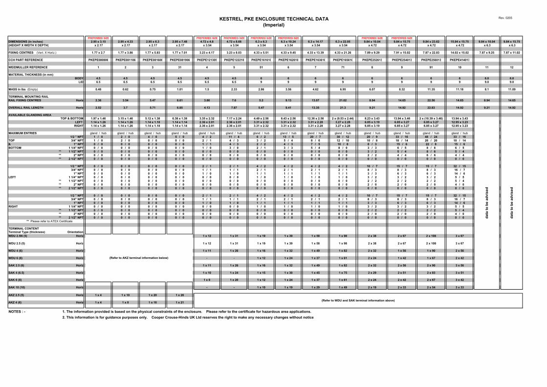
KESTREL, PKE ENCLOSURE TECHNICAL DATA(Imperial)
Rev. 0205
PREFERRED SIZE PREFERRED SIZE PREFERRED SIZE PREFERRED SIZE PREFERRED SIZE PREFERRED SIZE PREFERRED SIZEDIMENSIONS (in inches) 2.95 x 3.15 2.95 x 4.33 2.95 x 6.3 2.95 x 7.48 4.72 x 4.8 4.72 x 8.66 6.3 x 6.3 6.3 x 10.24 6.3 x 14.17 6.3 x 22.05 9.84 x 10.04 9.84 x 15.75 9.84 x 23.62 15.94 x 15.75 9.84 x 10.04 9.84 x 15.75(HEIGHT X WIDTH X DEPTH) x 2.17 x 2.17 x 2.17 x 2.17 x 3.54 x 3.54 x 3.54 x 3.54 x 3.54 x 3.54 x 4.72 x 4.72 x 4.72 x 4.72 x 6.3 x 6.3
FIXING CENTRES (Vert. X Horiz.) 1.77 x 2.7 1.77 x 3.86 1.77 x 5.83 1.77 x 7.01 3.23 x 4.17 3.23 x 8.03 4.33 x 5.51 4.33 x 9.45 4.33 x 13.39 4.33 x 21.26 7.89 x 9.29 7.91 x 15.02 7.87 x 22.83 14.02 x 15.02 7.87 x 9.25 7.87 x 11.02
CCH PART REFERENCE PKEPE080806 PKEPE081106 PKEPE081606 PKEPE081906 PKEPE121309 PKEPE122210 PKEPE161610 PKEPE162610 PKEPE163610 PKEPE165610 PKEPE252613 PKEPE254013 PKEPE256013 PKEPE414013
WEIDMULLER REFERENCE 1 2 3 31 4 5 51 6 7 71 8 9 91 10 11 12
MATERIAL THICKNESS (in mm)BODY 4.5 4.5 4.5 4.5 4.5 4.5 6 6 6 6 6 6 6 6 6.0 6.0
LID 6.5 6.5 6.5 6.5 6.5 6.5 9 9 9 9 9 9 9 9 9.0 9.0
MASS in lbs (Empty) 0.48 0.62 0.75 1.01 1.5 2.33 2.86 3.56 4.62 6.95 6.07 8.32 11.35 11.18 8.1 11.09
TERMINAL MOUNTING RAIL RAIL FIXING CENTRES Horiz 2.36 3.54 5.47 6.61 3.86 7.6 5.2 9.13 13.07 21.02 8.94 14.65 22.56 14.65 8.94 14.65
OVERALL RAIL LENGTH Horiz 2.52 3.7 5.71 6.85 4.13 7.87 5.47 9.41 13.35 21.3 9.21 14.92 22.83 14.92 9.21 14.92
AVAILABLE GLANDING AREA TOP & BOTTOM 1.97 x 1.46 3.15 x 1.46 5.12 x 1.38 6.38 x 1.38 3.35 x 2.32 7.17 x 2.24 4.49 x 2.56 8.43 x 2.56 12.36 x 2.56 2 x (9.53 x 2.44) 8.23 x 3.43 13.94 x 3.46 2 x (10.39 x 3.46) 13.94 x 3.43
LEFT 1.14 x 1.26 1.14 x 1.26 1.14 x 1.18 1.14 x 1.14 2.36 x 2.01 2.36 x 2.01 3.31 x 2.32 3.31 x 2.32 3.31 x 2.28 3.27 x 2.28 6.85 x 3.19 6.85 x 3.27 6.85 x 3.27 12.95 x 3.23RIGHT 1.14 x 1.26 1.14 x 1.26 1.14 x 1.18 1.14 x 1.14 2.36 x 2.01 2.36 x 2.01 3.31 x 2.32 3.31 x 2.32 3.31 x 2.28 3.27 x 2.28 6.85 x 3.19 6.85 x 3.27 6.85 x 3.27 12.95 x 3.23
MAXIMUM ENTRIES gland / hub gland / hub gland / hub gland / hub gland / hub gland / hub gland / hub gland / hub gland / hub gland / hub gland / hub gland / hub gland / hub gland / hub1/2 " NPT 1 / 0 2 / 0 4 / 0 5 / 0 4 / 2 11 / 4 6 / 2 13 / 5 20 / 7 30 / 12 20 / 9 33 / 16 48 / 24 33 / 16
TOP 3/4" NPT 1 / 0 2 / 0 0 / 0 0 / 0 2 / 1 4 / 3 3 / 2 5 / 4 8 / 6 12 / 10 10 / 8 18 / 14 26 / 20 18 / 14& 1" NPT 0 / 0 0 / 0 0 / 0 0 / 0 1 / 1 4 / 3 2 / 2 4 / 3 7 / 5 10 / 8 8 / 3 15 / 6 22 / 8 15 / 6BOTTOM 1 1/4" NPT 0 / 0 0 / 0 0 / 0 0 / 0 1 / 0 3 / 0 2 / 1 3 / 3 5 / 4 8 / 0 3 / 3 6 / 5 8 / 8 6 / 5
** 1 1/2" NPT 0 / 0 0 / 0 0 / 0 0 / 0 0 / 0 0 / 0 0 / 0 0 / 0 0 / 0 0 / 0 3 / 2 5 / 4 8 / 6 5 / 4** 2" NPT 0 / 0 0 / 0 0 / 0 0 / 0 0 / 0 0 / 0 0 / 0 0 / 0 0 / 0 0 / 0 2 / 2 4 / 4 6 / 6 4 / 4** 2 1/2" NPT 0 / 0 0 / 0 0 / 0 0 / 0 0 / 0 0 / 0 0 / 0 0 / 0 0 / 0 0 / 0 0 / 0 0 / 0 0 / 0 0 / 0
1/2 " NPT 0 / 0 0 / 0 0 / 0 0 / 0 2 / 1 2 / 1 4 / 2 4 / 2 4 / 2 4 / 2 10 / 7 15 / 7 15 / 7 32 / 153/4" NPT 0 / 0 0 / 0 0 / 0 0 / 0 1 / 1 1 / 1 2 / 1 2 / 1 2 / 1 2 / 1 8 / 3 8 / 3 8 / 3 16 / 7
1" NPT 0 / 0 0 / 0 0 / 0 0 / 0 1 / 0 1 / 0 1 / 1 1 / 1 1 / 1 1 / 1 3 / 3 6 / 3 6 / 3 14 / 6LEFT 1 1/4" NPT 0 / 0 0 / 0 0 / 0 0 / 0 0 / 0 0 / 0 1 / 0 1 / 0 1 / 0 1 / 0 3 / 2 3 / 2 3 / 2 5 / 5
** 1 1/2" NPT 0 / 0 0 / 0 0 / 0 0 / 0 0 / 0 0 / 0 0 / 0 0 / 0 0 / 0 0 / 0 2 / 2 2 / 2 2 / 2 5 / 4** 2" NPT 0 / 0 0 / 0 0 / 0 0 / 0 0 / 0 0 / 0 0 / 0 0 / 0 0 / 0 0 / 0 2 / 0 2 / 0 2 / 0 4 / 0** 2 1/2" NPT 0 / 0 0 / 0 0 / 0 0 / 0 0 / 0 0 / 0 0 / 0 0 / 0 0 / 0 0 / 0 0 / 0 0 / 0 0 / 0 0 / 0
1/2 " NPT 0 / 0 0 / 0 0 / 0 0 / 0 2 / 1 2 / 1 4 / 2 4 / 2 4 / 2 4 / 2 10 / 7 15 / 7 15 / 7 32 / 153/4" NPT 0 / 0 0 / 0 0 / 0 0 / 0 1 / 1 1 / 1 2 / 1 2 / 1 2 / 1 2 / 1 8 / 3 8 / 3 8 / 3 16 / 7
1" NPT 0 / 0 0 / 0 0 / 0 0 / 0 1 / 0 1 / 0 1 / 1 1 / 1 1 / 1 1 / 1 3 / 3 6 / 3 6 / 3 14 / 6RIGHT 1 1/4" NPT 0 / 0 0 / 0 0 / 0 0 / 0 0 / 0 0 / 0 1 / 0 1 / 0 1 / 0 1 / 0 3 / 2 3 / 2 3 / 2 5 / 5
** 1 1/2" NPT 0 / 0 0 / 0 0 / 0 0 / 0 0 / 0 0 / 0 0 / 0 0 / 0 0 / 0 0 / 0 2 / 2 2 / 2 2 / 2 5 / 4** 2" NPT 0 / 0 0 / 0 0 / 0 0 / 0 0 / 0 0 / 0 0 / 0 0 / 0 0 / 0 0 / 0 2 / 0 2 / 0 2 / 0 4 / 0** 2 1/2" NPT 0 / 0 0 / 0 0 / 0 0 / 0 0 / 0 0 / 0 0 / 0 0 / 0 0 / 0 0 / 0 0 / 0 0 / 0 0 / 0 0 / 0
** Please refer to ATEX Certificate
TERMINAL CONTENT Terminal Type (thickness) OrientationWDU 2.5N (5) Horiz 1 x 12 1 x 31 1 x 19 1 x 39 1 x 58 1 x 98 2 x 38 2 x 67 2 x 10⁸ 3 x 67
WDU 2.5 (5) Horiz 1 x 12 1 x 31 1 x 19 1 x 39 1 x 58 1 x 98 2 x 38 2 x 67 2 x 10⁸ 3 x 67
WDU 4 (6) Horiz 1 x 11 1 x 26 1 x 16 1 x 32 1 x 49 1 x 82 2 x 32 1 x 56 1 x 90 2 x 56
WDU 6 (8) Horiz - - 1 x 12 1 x 24 1 x 37 1 x 61 2 x 24 1 x 42 1 x 67 2 x 42
SAK 2.5 (6) Horiz 1 x 11 1 x 26 1 x 16 1 x 32 1 x 49 1 x 82 2 x 32 2 x 56 2 x 90 3 x 56
SAK 4 (6.5) Horiz 1 x 10 1 x 24 1 x 15 1 x 30 1 x 45 1 x 75 2 x 29 2 x 51 2 x 83 3 x 51
SAK 6 (8) Horiz 1 x 8 1 x 20 1 x 12 1 x 24 1 x 37 1 x 61 2 x 24 2 x 42 2 x 67 3 x 42
SAK 10 (10) Horiz - - 1 x 10 1 x 19 1 x 29 1 x 49 2 x 19 2 x 33 2 x 54 3 x 33
AKZ 2.5 (5) Horiz 1 x 4 1 x 10 1 x 20 1 x 26
AKZ 4 (6) Horiz 1 x 4 1 x 8 1 x 16 1 x 21
NOTES : - 1. The information provided is based on the physical constraints of the enclosure. Please refer to the certificate for hazardous area applications.2. This information is for guidance purposes only. Cooper Crouse-Hinds UK Ltd reserves the right to make any necessary changes without notice
(Refer to AKZ terminal information below)
data
to b
e ad
vise
d
data
to b
e ad
vise
d
(Refer to WDU and SAK terminal information above)
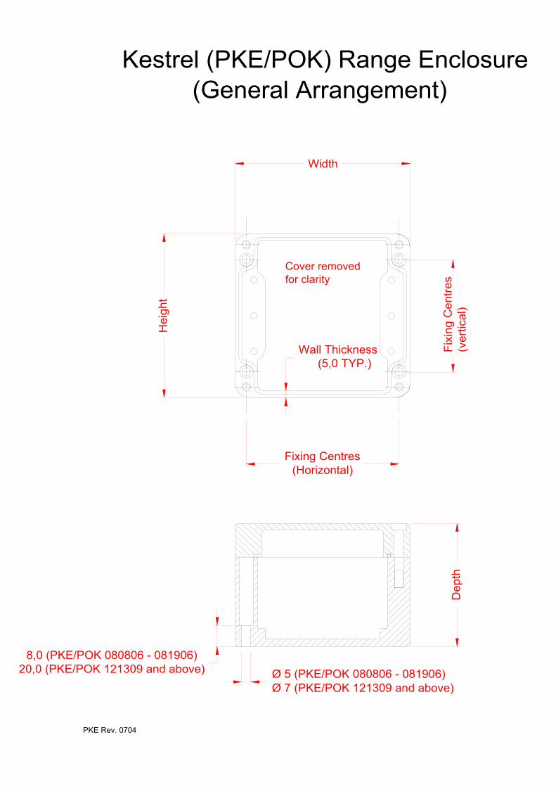
Width
Fix
ing
Cen
tres
(ver
tical
)
Ø 5 (PKE/POK 080806 - 081906)Ø 7 (PKE/POK 121309 and above)
8,0 (PKE/POK 080806 - 081906)20,0 (PKE/POK 121309 and above)
Hei
ght
Fixing Centres(Horizontal)
Wall Thickness(5,0 TYP.)
Dep
th
Cover removed for clarity
Kestrel (PKE/POK) Range Enclosure(General Arrangement)
PKE Rev. 0704
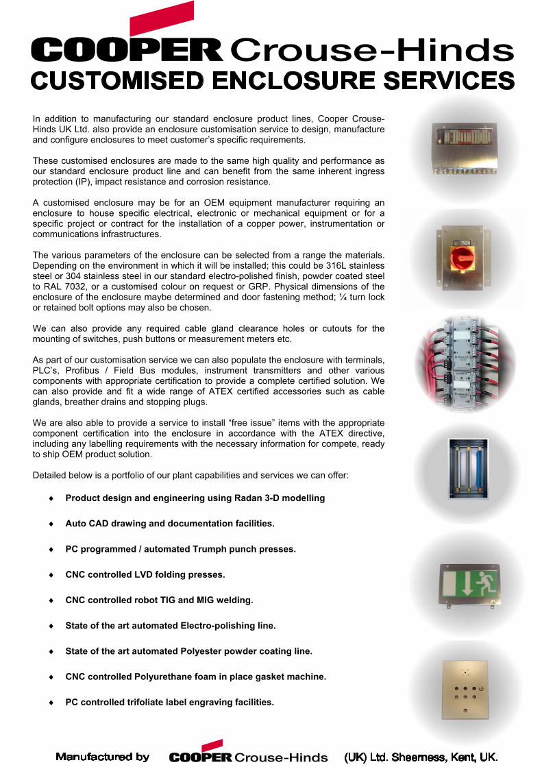
In addition to manufacturing our standard enclosure product lines, Cooper Crouse-Hinds UK Ltd. also provide an enclosure customisation service to design, manufactureand configure enclosures to meet customer’s specific requirements. These customised enclosures are made to the same high quality and performance asour standard enclosure product line and can benefit from the same inherent ingressprotection (IP), impact resistance and corrosion resistance. A customised enclosure may be for an OEM equipment manufacturer requiring anenclosure to house specific electrical, electronic or mechanical equipment or for aspecific project or contract for the installation of a copper power, instrumentation orcommunications infrastructures. The various parameters of the enclosure can be selected from a range the materials.Depending on the environment in which it will be installed; this could be 316L stainlesssteel or 304 stainless steel in our standard electro-polished finish, powder coated steelto RAL 7032, or a customised colour on request or GRP. Physical dimensions of theenclosure of the enclosure maybe determined and door fastening method; ¼ turn lockor retained bolt options may also be chosen. We can also provide any required cable gland clearance holes or cutouts for themounting of switches, push buttons or measurement meters etc. As part of our customisation service we can also populate the enclosure with terminals,PLC’s, Profibus / Field Bus modules, instrument transmitters and other variouscomponents with appropriate certification to provide a complete certified solution. Wecan also provide and fit a wide range of ATEX certified accessories such as cableglands, breather drains and stopping plugs. We are also able to provide a service to install “free issue” items with the appropriatecomponent certification into the enclosure in accordance with the ATEX directive,including any labelling requirements with the necessary information for compete, readyto ship OEM product solution. Detailed below is a portfolio of our plant capabilities and services we can offer:
♦
♦
♦
♦
♦
♦
♦
♦
♦
Product design and engineering using Radan 3-D modelling
Auto CAD drawing and documentation facilities.
PC programmed / automated Trumph punch presses.
CNC controlled LVD folding presses.
CNC controlled robot TIG and MIG welding.
State of the art automated Electro-polishing line.
State of the art automated Polyester powder coating line.
CNC controlled Polyurethane foam in place gasket machine.
PC controlled trifoliate label engraving facilities.
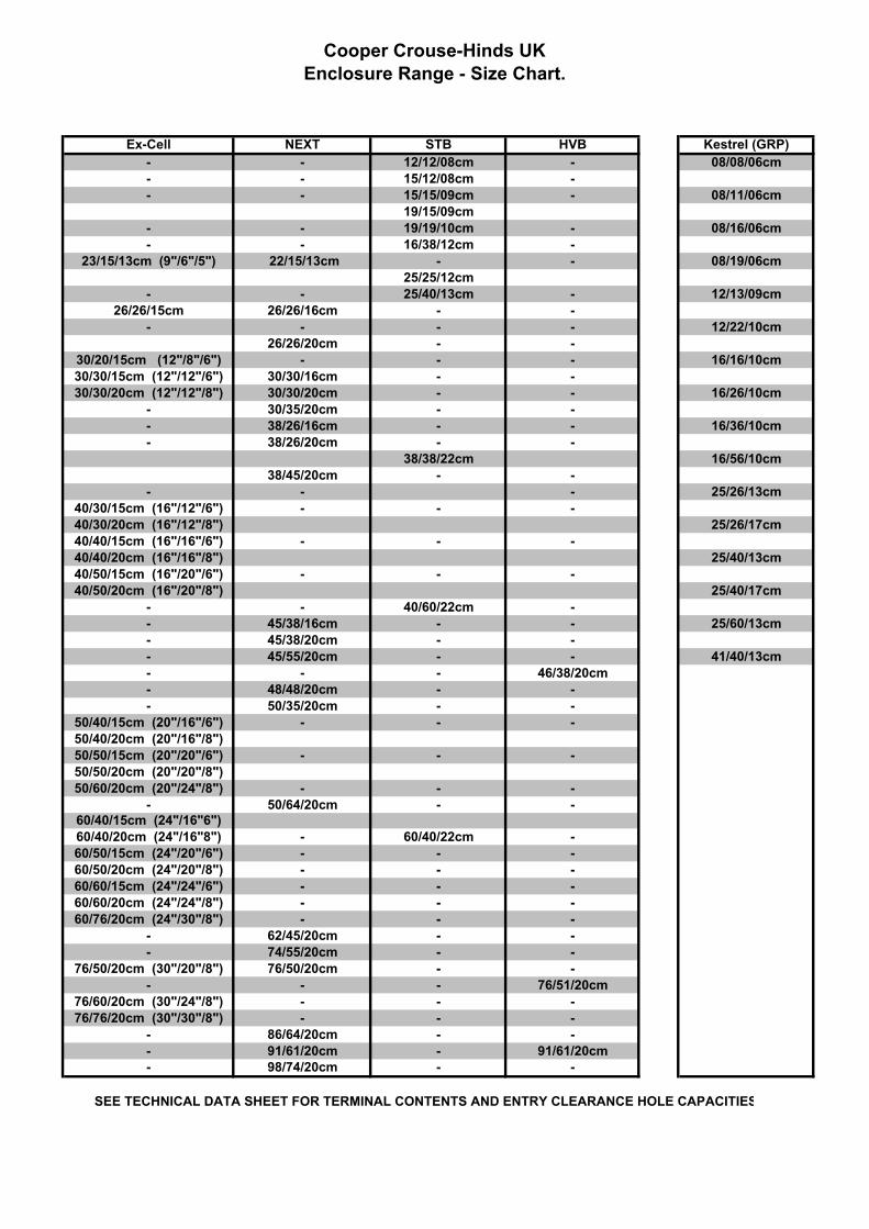
Cooper Crouse-Hinds UKEnclosure Range - Size Chart.
Ex-Cell NEXT STB HVB Kestrel (GRP)- - 12/12/08cm - 08/08/06cm- - 15/12/08cm -- - 15/15/09cm - 08/11/06cm
19/15/09cm- - 19/19/10cm - 08/16/06cm- - 16/38/12cm -
23/15/13cm (9"/6"/5") 22/15/13cm - - 08/19/06cm25/25/12cm
- - 25/40/13cm - 12/13/09cm26/26/15cm 26/26/16cm - -
- - - - 12/22/10cm26/26/20cm - -
30/20/15cm (12"/8"/6") - - - 16/16/10cm30/30/15cm (12"/12"/6") 30/30/16cm - -30/30/20cm (12"/12"/8") 30/30/20cm - - 16/26/10cm
- 30/35/20cm - -- 38/26/16cm - - 16/36/10cm- 38/26/20cm - -
38/38/22cm 16/56/10cm38/45/20cm - -
- - - 25/26/13cm40/30/15cm (16"/12"/6") - - -40/30/20cm (16"/12"/8") 25/26/17cm40/40/15cm (16"/16"/6") - - -40/40/20cm (16"/16"/8") 25/40/13cm40/50/15cm (16"/20"/6") - - -40/50/20cm (16"/20"/8") 25/40/17cm
- - 40/60/22cm -- 45/38/16cm - - 25/60/13cm- 45/38/20cm - -- 45/55/20cm - - 41/40/13cm- - - 46/38/20cm- 48/48/20cm - -- 50/35/20cm - -
50/40/15cm (20"/16"/6") - - -50/40/20cm (20"/16"/8")50/50/15cm (20"/20"/6") - - -50/50/20cm (20"/20"/8")50/60/20cm (20"/24"/8") - - -
- 50/64/20cm - -60/40/15cm (24"/16"6")60/40/20cm (24"/16"8") - 60/40/22cm -
60/50/15cm (24"/20"/6") - - -60/50/20cm (24"/20"/8") - - -60/60/15cm (24"/24"/6") - - -60/60/20cm (24"/24"/8") - - -60/76/20cm (24"/30"/8") - - -
- 62/45/20cm - -- 74/55/20cm - -
76/50/20cm (30"/20"/8") 76/50/20cm - -- - - 76/51/20cm
76/60/20cm (30"/24"/8") - - -76/76/20cm (30"/30"/8") - - -
- 86/64/20cm - -- 91/61/20cm - 91/61/20cm- 98/74/20cm - -
SEE TECHNICAL DATA SHEET FOR TERMINAL CONTENTS AND ENTRY CLEARANCE HOLE CAPACITIES