Embed Size (px)
Citation preview

Efficient ReconfigurableArchitectures for 3-D Medical
Image Compression
A thesis submitted for the degree of
Doctor of Philosophy
by
Afandi Ahmad
Supervisor
Dr Abbes Amira
Department Electronic and Computer Engineering
School of Engineering and Design
Brunel University, West London
July 2010

Abstract
Recently, the more widespread use of three-dimensional (3-D) imaging modalities,
such as magnetic resonance imaging (MRI), computed tomography (CT), positron
emission tomography (PET), and ultrasound (US) have generated a massive amount
of volumetric data. These have provided an impetus to the development of other
applications, in particular telemedicine and teleradiology. In these fields, medical
image compression is important since both efficient storage and transmission of data
through high-bandwidth digital communication lines are of crucial importance.
Despite their advantages, most 3-D medical imaging algorithms are
computationally intensive with matrix transformation as the most fundamental
operation involved in the transform-based methods. Therefore, there is a real
need for high-performance systems, whilst keeping architectures flexible to allow
for quick upgradeability with real-time applications. Moreover, in order to obtain
efficient solutions for large medical volumes data, an efficient implementation of
these operations is of significant importance. Reconfigurable hardware, in the form
of field programmable gate arrays (FPGAs) has been proposed as viable system
building block in the construction of high-performance systems at an economical price.
Consequently, FPGAs seem an ideal candidate to harness and exploit their inherent
advantages such as massive parallelism capabilities, multimillion gate counts, and
special low-power packages.
The key achievements of the work presented in this thesis are summarised
as follows. Two architectures for 3-D Haar wavelet transform (HWT) have been
proposed based on transpose-based computation and partial reconfiguration suitable
for 3-D medical imaging applications. These applications require continuous hardware
servicing, and as a result dynamic partial reconfiguration (DPR) has been introduced.
Comparative study for both non-partial and partial reconfiguration implementation
has shown that DPR offers many advantages and leads to a compelling solution
for implementing computationally intensive applications such as 3-D medical image
compression. Using DPR, several large systems are mapped to small hardware

iv
resources, and the area, power consumption as well as maximum frequency are
optimised and improved.
Moreover, an FPGA-based architecture of the finite Radon transform (FRAT)
with three design strategies has been proposed: direct implementation of pseudo-code
with a sequential or pipelined description, and block random access memory (BRAM)-
based method. An analysis with various medical imaging modalities has been carried
out. Results obtained for image de-noising implementation using FRAT exhibits
promising results in reducing Gaussian white noise in medical images. In terms of
hardware implementation, promising trade-offs on maximum frequency, throughput
and area are also achieved.
Furthermore, a novel hardware implementation of 3-D medical image
compression system with context-based adaptive variable length coding (CAVLC)
has been proposed. An evaluation of the 3-D integer transform (IT) and the discrete
wavelet transform (DWT) with lifting scheme (LS) for transform blocks reveal that
3-D IT demonstrates better computational complexity than the 3-D DWT, whilst
the 3-D DWT with LS exhibits a lossless compression that is significantly useful for
medical image compression. Additionally, an architecture of CAVLC that is capable
of compressing high-definition (HD) images in real-time without any buffer between
the quantiser and the entropy coder is proposed. Through a judicious parallelisation,
promising results have been obtained with limited resources.
In summary, this research is tackling the issues of massive 3-D medical volumes
data that requires compression as well as hardware implementation to accelerate the
slowest operations in the system. Results obtained also reveal a significant achievement
in terms of the architecture efficiency and applications performance.

List of Abbreviations
µblaze Micro blaze
1-D One-dimensional
2-D Two-dimensional
3-D Three-dimensional
AG Address generator
AGWN Additive Gaussian white noise
ASIC Application specific integrated circuit
ALU Arithmetic logic unit
BLV Brent. Luk, Van
BPV Bit per voxel
BRAM Block random access memory
CABAC Context-based adaptive binary arithmetic coding
CAVLC Context-based adaptive variable length coding
CDF Cohen-Daubechies-Favreau
CIF Common intermediate format
CORDIC Coordinate rotation digital computer
CPU Central processing units
CR Compression ratio
CSD Canonical sign digit
CT Computed tomography
CUDA Compute unified device architecture
DA Distributed arithmetic
xii

xiii
DCM Digital clock management
DCT Discrete cosine transform
DDR-2 Double data rate
DFF D flip-flop
DFT Discrete Fourier transform
DHT Discrete Hartley transform
DMA Distortion minimisation algorithm
DPR Dynamic partial reconfiguration
DSP Digital signal processor
DWT Discrete wavelet transform
EAPR Early access partial reconfiguration
EDA Electronic design automation
ESCOT Embedded sub-band coding with optimal truncation
ESM Erlangen slot machine
EVD Eigen value decomposition
FIR Finite impulse response
FFT Fast Fourier transform
FIFO First in first out
FMRI Functional magnetic resonance imaging
FPGA Field programmable gate array
fps Frames per second
FRAT Finite Radon transform
FRIT Finite ridgelet transform
FWT Fast wavelet transform
GOP Group of pictures
GPGPU General-purpose computation on graphics processing units
GPP General purpose processor
GPU Graphics processing unit
HBWD Hierarchical block wavelet decomposition
HD High-definition

xiv
HDMI High-definition medical imaging
HDTV High-definition TV
HLL High-level language
HW Hardware
HWT Haar wavelet transform
HVS Human visual system
I/O Input/output
IOB Input/output block
ICAP Internal configuration access port
ILA Integrated logic analyzer
IT Integer transform
IRT Inverse Radon transform
JPEG Joint photographic experts group
LC Logic cell
LUT Look-up tables
MAV Median absolute value
MPGA Mask programmable gate array
MRI Magnetic resonance imaging
MSE Mean square error
NCD Native circuit description
NFS Networking file system
NMC Native macro circuit
NSWD Non-standard wavelet decomposition
NTSC National television system committee
OT Objective test
PAL Programmable arrays logic
PAL Phase alternate line
PAR Place and route
PC Personal computer
PCI Peripheral component interconnect

xv
PET Positron emission tomography
PLL Phase-locked-loop
PR Partial reconfiguration
PSNR Peak signal to noise ratio
QCIF Quarter common intermediate format
RAM Random access memory
RH Reconfigurable hardware
ROM Read only memory
ROI Regions of interest
RPM Reconfigurable processing modules
RT Radon transform
RTL Register-transfer level
RTR Run-time reconfiguration
SoPC Systems on a programmable chip
SPIHT Set partitioning in hierarchical trees
SRAM Static RAM
ST Subjective test
STFT Short time Fourier transform
SVD Singular value decomposition
SW Software
SWD Standard wavelet decomposition
UCF User constraint file
UK United Kingdom
US Ultrasound
VGA Video graphic array
VHDL Very-high-speed integrated circuit hardware description language
VLC Variable length coding
VLSI Very large scale integration
XE Xilinx edition

Table of Contents
Abstract iii
Declaration v
Acknowledgements vii
Author’s Publications viii
1 Introduction 1
1.1 Overview . . . . . . . . . . . . . . . . . . . . . . . . . . . . . . . . . . 1
1.2 Three-dimensional (3-D) Medical Image Processing . . . . . . . . . . . 5
1.3 High-Performance Solutions for Medical Image Processing Applications 10
1.3.1 Digital Signal Processor (DSP) . . . . . . . . . . . . . . . . . . 11
1.3.2 Special Purpose Application Specific Integrated Circuit (ASIC)
Hardware . . . . . . . . . . . . . . . . . . . . . . . . . . . . . . 12
1.3.3 Graphical Processing Unit (GPU) . . . . . . . . . . . . . . . . 13
1.3.4 Reconfigurable Hardware (RH): A Review of Field
Programmable Gate Array (FPGA) . . . . . . . . . . . . . . . 15
1.4 Design and Implementation Strategies . . . . . . . . . . . . . . . . . . 18
1.5 Motivation and Research Objectives . . . . . . . . . . . . . . . . . . . 19
xvi

Table of Contents xvii
1.6 Overall Contribution . . . . . . . . . . . . . . . . . . . . . . . . . . . . 22
1.7 Thesis Organisation . . . . . . . . . . . . . . . . . . . . . . . . . . . . 24
2 Related Work 25
2.1 Overview . . . . . . . . . . . . . . . . . . . . . . . . . . . . . . . . . . 25
2.2 Medical Image Compression . . . . . . . . . . . . . . . . . . . . . . . . 27
2.3 Reconfigurable Architectures . . . . . . . . . . . . . . . . . . . . . . . 34
2.3.1 FPGA-based Architectures for 3-D Discrete Wavelet Transform
(DWT) . . . . . . . . . . . . . . . . . . . . . . . . . . . . . . . 34
2.3.2 FPGA-based Architectures for Finite Radon Transform (FRAT) 40
2.3.3 FPGA-based Architectures for Context-based Adaptive Variable
Length Coding (CAVLC) . . . . . . . . . . . . . . . . . . . . . 51
2.4 Dynamic Partial Reconfiguration (DPR) . . . . . . . . . . . . . . . . . 58
2.5 Limitation of Existing Work and Research Opportunities . . . . . . . 61
2.6 Summary . . . . . . . . . . . . . . . . . . . . . . . . . . . . . . . . . . 63
3 Efficient Architectures for 3-D HWT using DPR 64
3.1 Overview . . . . . . . . . . . . . . . . . . . . . . . . . . . . . . . . . . 64
3.2 Mathematical Background and Design Methodology . . . . . . . . . . 65
3.2.1 3-D Haar Wavelet Transform (HWT) and Matrix Transposition 65
3.2.2 Pipelined Direct Mapping Implementation . . . . . . . . . . . . 68
3.3 Proposed Architectures . . . . . . . . . . . . . . . . . . . . . . . . . . 69
3.3.1 Proposed System Applications . . . . . . . . . . . . . . . . . . 69
3.3.2 3-D Haar Wavelet Transform (HWT) with Transpose-based
Computation . . . . . . . . . . . . . . . . . . . . . . . . . . . . 70

Table of Contents xviii
3.3.3 3-D Haar Wavelet Transform (HWT) with Dynamic Partial
Reconfiguration (DPR) . . . . . . . . . . . . . . . . . . . . . . 73
3.4 Experimental Results and Analysis . . . . . . . . . . . . . . . . . . . . 76
3.4.1 Field Programmable Gate Array (FPGA) Implementation . . . 76
3.4.2 Discussions . . . . . . . . . . . . . . . . . . . . . . . . . . . . . 78
3.5 Summary . . . . . . . . . . . . . . . . . . . . . . . . . . . . . . . . . . 82
4 FPGA-based Architectures of FRAT for Medical Image De-noising 84
4.1 Overview . . . . . . . . . . . . . . . . . . . . . . . . . . . . . . . . . . 84
4.2 Mathematical Background and Design Methodology . . . . . . . . . . 86
4.2.1 Radon Transform (RT) . . . . . . . . . . . . . . . . . . . . . . 86
4.2.2 Finite Radon Transform (FRAT) . . . . . . . . . . . . . . . . . 88
4.2.3 Xilinx AccelDSP Design Flow . . . . . . . . . . . . . . . . . . . 89
4.3 Proposed System Implementations . . . . . . . . . . . . . . . . . . . . 91
4.3.1 Systems Applications . . . . . . . . . . . . . . . . . . . . . . . 91
4.3.2 Proposed Architecture and Design Strategies . . . . . . . . . . 93
4.4 Results and Analysis . . . . . . . . . . . . . . . . . . . . . . . . . . . . 96
4.4.1 Medical Image De-noising . . . . . . . . . . . . . . . . . . . . . 100
4.4.2 Software Simulation . . . . . . . . . . . . . . . . . . . . . . . . 101
4.4.3 Hardware Implementation . . . . . . . . . . . . . . . . . . . . . 103
4.5 Summary . . . . . . . . . . . . . . . . . . . . . . . . . . . . . . . . . . 105
5 FPGA-based Implementation of a 3-D Medical Image Compression
System using CAVLC 106
5.1 Overview . . . . . . . . . . . . . . . . . . . . . . . . . . . . . . . . . . 106
5.2 Algorithms and Methodology . . . . . . . . . . . . . . . . . . . . . . . 108

Table of Contents xix
5.2.1 3-D Integer Transform (IT) . . . . . . . . . . . . . . . . . . . . 108
5.2.2 3-D Discrete Wavelet Transform (DWT) . . . . . . . . . . . . . 111
5.2.3 Decomposition Strategies . . . . . . . . . . . . . . . . . . . . . 112
5.3 Proposed System Architectures . . . . . . . . . . . . . . . . . . . . . . 114
5.3.1 Transform Block . . . . . . . . . . . . . . . . . . . . . . . . . . 115
5.3.2 Quantisation and Reordering Block . . . . . . . . . . . . . . . . 116
5.3.3 Context-based Adaptive Variable Length Coding (CAVLC) Block117
5.4 Results and Analysis . . . . . . . . . . . . . . . . . . . . . . . . . . . . 122
5.4.1 Computational Complexity . . . . . . . . . . . . . . . . . . . . 122
5.4.2 Objective Evaluation . . . . . . . . . . . . . . . . . . . . . . . . 123
5.4.3 Field Programmable Gate Array (FPGA) Implementation . . . 127
5.5 Summary . . . . . . . . . . . . . . . . . . . . . . . . . . . . . . . . . . 131
6 Conclusions and Future Work 133
6.1 Overview . . . . . . . . . . . . . . . . . . . . . . . . . . . . . . . . . . 133
6.2 Achievements . . . . . . . . . . . . . . . . . . . . . . . . . . . . . . . . 134
6.3 Limitations . . . . . . . . . . . . . . . . . . . . . . . . . . . . . . . . . 135
6.4 Future Work . . . . . . . . . . . . . . . . . . . . . . . . . . . . . . . . 136
Appendices 139
A Rapid Prototyping Board and FPGA Devices 139
A.1 Overview . . . . . . . . . . . . . . . . . . . . . . . . . . . . . . . . . . 139
A.2 XUPV5-LX110T Prototyping Board . . . . . . . . . . . . . . . . . . . 139
A.3 Virtex-5 Field Programmable Gate Array (FPGA) . . . . . . . . . . . 140
A.3.1 Configurable Logic Block (CLB) . . . . . . . . . . . . . . . . . 142

Table of Contents xx
A.3.2 Block Random Access Memory (BRAM) . . . . . . . . . . . . . 142
A.3.3 Digital Signal Processor (DSP) Element . . . . . . . . . . . . . 143
A.4 Comparison . . . . . . . . . . . . . . . . . . . . . . . . . . . . . . . . . 144
B Xilinx ISE and FPGA Programming 146
B.1 Overview . . . . . . . . . . . . . . . . . . . . . . . . . . . . . . . . . . 146
B.2 Implementing VHDL Design . . . . . . . . . . . . . . . . . . . . . . . . 148
B.2.1 Xilinx ISE . . . . . . . . . . . . . . . . . . . . . . . . . . . . . . 148
B.2.2 Field Programmable Gate Array (FPGA) Configuration . . . . 153
C Partial Reconfiguration (PR) in Xilinx FPGA Devices 155
C.1 Overview . . . . . . . . . . . . . . . . . . . . . . . . . . . . . . . . . . 155
C.2 Design Requirements . . . . . . . . . . . . . . . . . . . . . . . . . . . . 156
C.3 Implementation Design Flow . . . . . . . . . . . . . . . . . . . . . . . 156
D Xilinx AccelDSP Synthesis Tool 160
D.1 Overview . . . . . . . . . . . . . . . . . . . . . . . . . . . . . . . . . . 160
D.2 Design Flow and Operations . . . . . . . . . . . . . . . . . . . . . . . . 160
Bibliography 163

List of Figures
1.1 Number of new cases of all malignant neoplasms in UK 2007 (Excluding
non-melanoma skin cancer) [2]. . . . . . . . . . . . . . . . . . . . . . . 2
1.2 Medical image features. . . . . . . . . . . . . . . . . . . . . . . . . . . 6
1.3 Examples of medical images (a) Sagittal MRI knee image (b) Transaxial
CT lung slice (c) PET scan for lymphoma [22]. . . . . . . . . . . . . . 6
1.4 3-D medical image features. . . . . . . . . . . . . . . . . . . . . . . . . 7
1.5 3-D medical image data processing. . . . . . . . . . . . . . . . . . . . . 7
1.6 Survey on medical image processing. . . . . . . . . . . . . . . . . . . . 8
1.7 DSPs features for performance accelerations. . . . . . . . . . . . . . . 11
1.8 Main disadvantages of ASICs. . . . . . . . . . . . . . . . . . . . . . . . 13
1.9 Architecture comparison (a) CPU (b) GPU [47]. . . . . . . . . . . . . 14
1.10 Xilinx’s FPGA structure with internal blocks. . . . . . . . . . . . . . . 17
1.11 Generic design and implementation strategies. . . . . . . . . . . . . . . 19
1.12 Overall design flow. . . . . . . . . . . . . . . . . . . . . . . . . . . . . 20
1.13 Overall research approaches and contributions. . . . . . . . . . . . . . 23
2.1 Structure of related research issues. . . . . . . . . . . . . . . . . . . . . 26
2.2 Compression system. . . . . . . . . . . . . . . . . . . . . . . . . . . . . 27
2.3 Implementation based on parallel computing [7]. . . . . . . . . . . . . 28
xxi

List of Figures xxii
2.4 The 3-D DWT process. . . . . . . . . . . . . . . . . . . . . . . . . . . 34
2.5 Block architecture for the 3-D DWT [66]. . . . . . . . . . . . . . . . . 36
2.6 3-D DWT processor architecture [9]. . . . . . . . . . . . . . . . . . . . 37
2.7 Design of 3D-V temporal decomposition system [67]. . . . . . . . . . . 38
2.8 Hardware design for the 3-D Haar wavelet transform [68]. . . . . . . . 38
2.9 Proposed architectures (a) Generic transform architecture (b) Radon
transform module [73]. . . . . . . . . . . . . . . . . . . . . . . . . . . . 41
2.10 (a) Reference FRAT architecture (b) Memoryless FRAT architecture [75]. 42
2.11 Block diagram of proposed FRAT implementation [72]. . . . . . . . . . 43
2.12 (a) Serial architecture (b) Parallel architecture [76]. . . . . . . . . . . . 44
2.13 (a) Reference architecture (b) FRIT architecture with the FRAT [71]. 45
2.14 Review of FRAT’s FPGA-based implementation. . . . . . . . . . . . . 47
2.15 FPGA implementation of the proposed wavelet-domain video denoising
algorithm [84]. . . . . . . . . . . . . . . . . . . . . . . . . . . . . . . . 47
2.16 FPGA implementation of the SVD/EVD array [85]. . . . . . . . . . . 48
2.17 Block diagram of the proposed FPGA design [88]. . . . . . . . . . . . 50
2.18 CAVLC hardware architecture [100]. . . . . . . . . . . . . . . . . . . . 53
2.19 The proposed CAVLC architecture [101]. . . . . . . . . . . . . . . . . . 54
2.20 (a) Architecture of targeted many-core system (b) Data flow diagram
of the CAVLC encoder [102]. . . . . . . . . . . . . . . . . . . . . . . . 55
2.21 Framework of CAVLC encoder [104]. . . . . . . . . . . . . . . . . . . . 57
2.22 Overview of the partitioning scheme approaches (a) 1-D (b) Multi-1-D
(c) 2-D [112]. . . . . . . . . . . . . . . . . . . . . . . . . . . . . . . . . 59
3.1 3-D HWT expression. . . . . . . . . . . . . . . . . . . . . . . . . . . . 66

List of Figures xxiii
3.2 Decomposition based on tensor product of 1-D filters (a) Original image
volume (b) Image volume partitioned into 2× 2× 2 sub-blocks (c) One
overall low-pass coefficient is obtained from each sub-block after the
first decomposition stage (d) All sub-block averaging coefficients are
clustered to form new sub-blocks, which are then decomposed further
to obtain one overall low-pass coefficient (e) Image after two stage
decomposition on a 4× 4× 4 image volume. . . . . . . . . . . . . . . . 67
3.3 Transposition of a matrix. . . . . . . . . . . . . . . . . . . . . . . . . . 68
3.4 1-D HWT flow diagram with N -inputs sample for direct mapped
architecture. . . . . . . . . . . . . . . . . . . . . . . . . . . . . . . . . . 69
3.5 Proposed system architectures (a) Compression system
overview (b) Architecture for 3-D HWT with transpose-based
computation (c) Input data for sub-images for [I]z (d) Transpose
matrix after T1 (e) Transpose matrix after T2. . . . . . . . . . . . . . . 70
3.6 Proposed reconfigurable and adaptive system architectures. . . . . . . 73
3.7 Proposed top architecture of 3-D HWT (a) Without DPR (b) With DPR. 74
3.8 Partial reconfiguration design flow (a) Steps for partial design
flow (b) Define static and reconfigurable modules. . . . . . . . . . . . . 75
3.9 Influence of transform size on area. . . . . . . . . . . . . . . . . . . . . 78
3.10 Influence of transform size on power consumption. . . . . . . . . . . . 79
3.11 Influence of transform size on maximum frequency for 1-D HWT modules. 79
3.12 Comparison on maximum frequency achievement for transpose function. 80
3.13 Comparison of chip layout for different Virtex-5 devices for N = 64. . 80
4.1 Transform flow graph (a) Ridgelet transform (b) Curvelet transform. . 85
4.2 Radon transform representation. . . . . . . . . . . . . . . . . . . . . . 87

List of Figures xxiv
4.3 Proposed system applications (a) Image de-noising (b) Compression
system. . . . . . . . . . . . . . . . . . . . . . . . . . . . . . . . . . . . 91
4.4 Proposed reference architecture for the FRAT. . . . . . . . . . . . . . 94
4.5 Implementation strategies (a) Sequential (b) Pipelined (c) BRAM-based
method. . . . . . . . . . . . . . . . . . . . . . . . . . . . . . . . . . . . 95
4.6 Script and function files for the sequential implementation. . . . . . . 97
4.7 Function operations with generated fixed point report. . . . . . . . . . 98
4.8 Project explorer with VHDL files generated. . . . . . . . . . . . . . . . 99
4.9 Gaussian noise reduction experimental results on MRI image (a) Original
(b) Noisy (c) De-noising. . . . . . . . . . . . . . . . . . . . . . . . . . . 101
4.10 Original and blockiness images. . . . . . . . . . . . . . . . . . . . . . . 101
4.11 Analysis of PSNR with different block sizes (p). . . . . . . . . . . . . . 102
4.12 Chip layout for the sequential implementation. . . . . . . . . . . . . . 104
5.1 Coefficient orderings (a) Convolution-based (b) Lifting-based. . . . . . 112
5.2 Sub-band structure obtained via a three level SWD. . . . . . . . . . . 114
5.3 Proposed system overview. . . . . . . . . . . . . . . . . . . . . . . . . 114
5.4 Butterfly architecture of 1-D IT. . . . . . . . . . . . . . . . . . . . . . 115
5.5 A simple lifting-based perfect reconstruction encoder. . . . . . . . . . 116
5.6 Block diagram of CAVLC architecture. . . . . . . . . . . . . . . . . . . 120
5.7 Encode level detail of the CAVLC architecture. . . . . . . . . . . . . 122
5.8 PSNR vs. BPV for CT. . . . . . . . . . . . . . . . . . . . . . . . . . . 125
5.9 PSNR vs. BPV for MRI. . . . . . . . . . . . . . . . . . . . . . . . . . 125
5.10 PSNR vs. BPV for PET. . . . . . . . . . . . . . . . . . . . . . . . . . 126
5.11 Comparison of original and reconstructed CT, MRI and PET images
for the first slices. . . . . . . . . . . . . . . . . . . . . . . . . . . . . . . 127

List of Figures xxv
5.12 Compression system. . . . . . . . . . . . . . . . . . . . . . . . . . . . . 128
5.13 Power consumption comparison for the CAVLC architecture. . . . . . 131
A.1 Virtex-5 FPGA and XUPV5-LX110T platform block diagram [146]. . 140
A.2 Detailed description of XUPV5-LX110T platform components (front
view). . . . . . . . . . . . . . . . . . . . . . . . . . . . . . . . . . . . . 141
A.3 Arrangement of slices within the CLB for Virtex-5 [146]. . . . . . . . . 142
A.4 Details of CLBs and slices for Virtex-5 [146]. . . . . . . . . . . . . . . 143
B.1 General design route from VHDL to prototyping board. . . . . . . . . 147
B.2 Sample window displaying ISE project navigator. . . . . . . . . . . 149
B.3 ModelSim simulator window. . . . . . . . . . . . . . . . . . . . . . . . 149
B.4 Setting the design options in ISE. . . . . . . . . . . . . . . . . . . . . . 150
B.5 Setting for UCF. . . . . . . . . . . . . . . . . . . . . . . . . . . . . . . 151
B.6 Floorplan for pin location constraints. . . . . . . . . . . . . . . . . . . 151
B.7 FPGA editor window. . . . . . . . . . . . . . . . . . . . . . . . . . . . 152
B.8 Device configuration using iMPACT. . . . . . . . . . . . . . . . . . . . 153
B.9 Program succeeded to be downloaded. . . . . . . . . . . . . . . . . . . 154
B.10 Results verification using LEDs indicator. . . . . . . . . . . . . . . . . 154
C.1 Basic concept of partial reconfiguration. . . . . . . . . . . . . . . . . . 155
C.2 Design tools requirement in PR. . . . . . . . . . . . . . . . . . . . . . 157
C.3 General PR design flow. . . . . . . . . . . . . . . . . . . . . . . . . . . 157
C.4 Overview of PR software design flow. . . . . . . . . . . . . . . . . . . . 158
D.1 Advantages of AccelDSP synthesis tool. . . . . . . . . . . . . . . . . . 161
D.2 The AccelDSP ISE synthesis work flow. . . . . . . . . . . . . . . . . . 162

List of Tables
1.1 Summary of programming technologies [17]. . . . . . . . . . . . . . . . 4
1.2 Comparison of different implementation approaches. . . . . . . . . . . 5
1.3 Survey on medical image processing. . . . . . . . . . . . . . . . . . . 9
2.1 Device utilisation [8]. . . . . . . . . . . . . . . . . . . . . . . . . . . . . 29
2.2 Summary of 3-D medical image compression systems. . . . . . . . . . 33
2.3 Comparative study of the 3-D DWT architectures and the FPGA
implementations. . . . . . . . . . . . . . . . . . . . . . . . . . . . . . 39
2.4 Summary of FPGA-based architectures of FRAT. . . . . . . . . . . . 46
2.5 Hardware implementation of medical image de-noising. . . . . . . . . 51
2.6 Equivalent gate for CAVLC items [103]. . . . . . . . . . . . . . . . . . 56
2.7 Summary of hardware implementation of CAVLC. . . . . . . . . . . . 58
3.1 Resources utilisation and overall proposed architectures performance
on XC5VLX110T-3FF113. . . . . . . . . . . . . . . . . . . . . . . . . . 77
3.2 Comparison of bitstream generated and configuration times towards
transform sizes. . . . . . . . . . . . . . . . . . . . . . . . . . . . . . . . 77
3.3 Device summary report of the proposed architecture on
XC5VLX30T-3FF323. . . . . . . . . . . . . . . . . . . . . . . . . . . . 82
xxvi

List of Tables xxvii
4.1 PSNR quantitative results of noisy image with a Gaussian white noise
and MRI image. . . . . . . . . . . . . . . . . . . . . . . . . . . . . . . 100
4.2 Comparison of performance with existing architectures for the case
p = 7. . . . . . . . . . . . . . . . . . . . . . . . . . . . . . . . . . . . 103
4.3 Comparison of PSNR values for CT images. . . . . . . . . . . . . . . . 104
5.1 Computational complexity of the main functional blocks with various
decomposition approaches. . . . . . . . . . . . . . . . . . . . . . . . . . 123
5.2 Images used for testing. . . . . . . . . . . . . . . . . . . . . . . . . . . 124
5.3 Hardware resources utilisation for each block. . . . . . . . . . . . . . 128
5.4 Resources utilisation and overall transform architectures performance
for N = 4. . . . . . . . . . . . . . . . . . . . . . . . . . . . . . . . . . 129
5.5 FPGA implementation results of CAVLC. . . . . . . . . . . . . . . . . 130
5.6 Comparison of CAVLC architectures performance on FPGA platforms. 130
A.1 Comparison of selected Xilinx FPGA devices resources. . . . . . . . . 145
C.1 Description of files format for PR process. . . . . . . . . . . . . . . . . 159

Chapter 1
Introduction
1.1 Overview
Medical imaging as an indispensable part of medical management of diseases appears
as one of the most challenges areas and its full potential seems to be boundary-less.
Doubtless, that medical imaging applications deal with massive amounts of data and
Lee et al. [1] disclose an interesting fact on this issue:
“The University of Washington Medical Centre, a medium-sized hospital with about
400 beds, performs approximately 80,000 studies per year. At 30 Mbytes per study,
the amount of digital images generated is 2.4 Tera (1012) bytes of data per year or
approximately 10 Gbytes per day”.
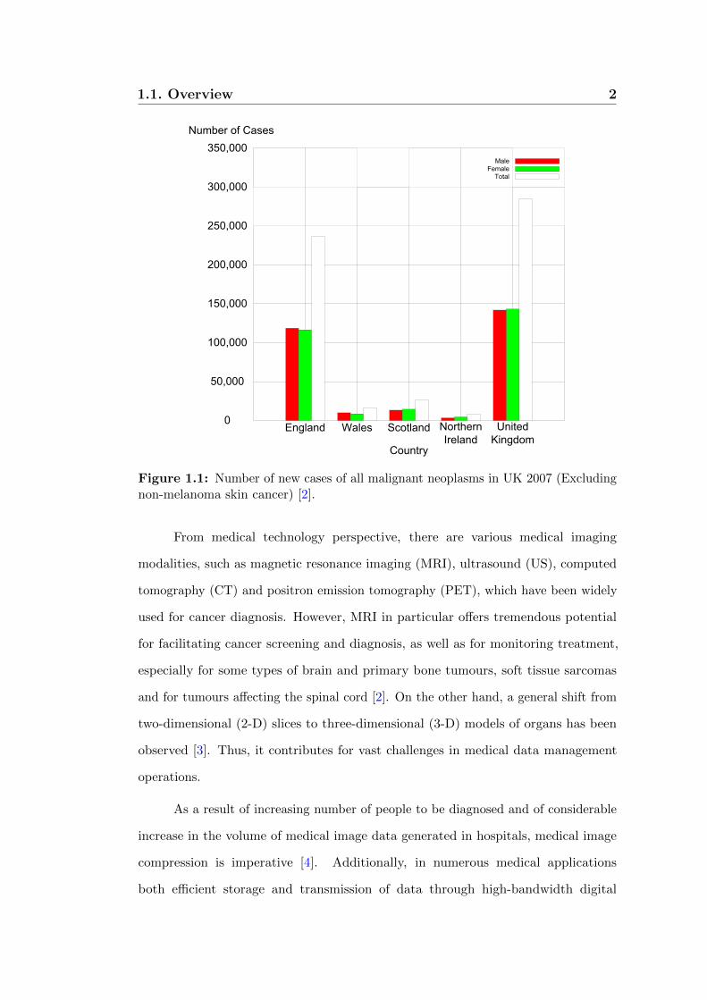
To further highlight the issues and challenges ahead in these areas, in 2007,
there were more than 155,000 cancer deaths in the United Kingdom (UK), and one in
four (27%) of all deaths in the UK were due to cancer. Moreover, with more than
200 different types of cancer, empirical data shown in Figure 1.1 exposes 289,000 new
cases of cancer diagnosed each year in the UK [2].
1
1.1. Overview 2
Figure 1.1: Number of new cases of all malignant neoplasms in UK 2007 (Excludingnon-melanoma skin cancer) [2].
From medical technology perspective, there are various medical imaging
modalities, such as magnetic resonance imaging (MRI), ultrasound (US), computed
tomography (CT) and positron emission tomography (PET), which have been widely
used for cancer diagnosis. However, MRI in particular offers tremendous potential
for facilitating cancer screening and diagnosis, as well as for monitoring treatment,
especially for some types of brain and primary bone tumours, soft tissue sarcomas
and for tumours affecting the spinal cord [2]. On the other hand, a general shift from
two-dimensional (2-D) slices to three-dimensional (3-D) models of organs has been
observed [3]. Thus, it contributes for vast challenges in medical data management
operations.
As a result of increasing number of people to be diagnosed and of considerable
increase in the volume of medical image data generated in hospitals, medical image
compression is imperative [4]. Additionally, in numerous medical applications
both efficient storage and transmission of data through high-bandwidth digital

1.1. Overview 3
communication lines are of crucial. Moreover, it is well known also that noise on
medical image resulting in low image quality, and yet limits the diagnostic effectiveness.
Therefore, the field of medical imaging introduces a complex problem [5]. In the case
of medical image compression for instance, it is mainly involves matrix transforms,
repeatedly on a large set of image data, often under real-time requirements. As a result,
there is a need for high-performance systems whilst keeping architectures flexible to
allow for quick upgradeability. A lot of effort in research and development has been
dedicated to computer and processor architectures suitable for such applications [6–10].
Spectrum of possible hardware solution has grown enormously. At one end of
the spectrum are processors such as general purpose processors (GPPs) or digital
signal processors (DSPs), which have an instruction-set architecture. They provide
the possibility of processing arbitrary computations due to their architectural concept.
Pursuant to the overhead paid for the flexibility, processors are rather inefficient
regarding performance and power consumption [11]. At the other end of the spectrum
is application specific integrated circuits (ASICs), which contain dedicated circuits
specialised to a particular set of functions. Thus, the architecture is optimally suited for
the functions at hand which is the reason of ASICs are efficient regarding performance
and power consumption, but they lack flexibility, as no programmable resources are
provided [11].
Due to the high demand of graphics processing of the video game industry,
graphics processing units (GPUs) have evolved into massively parallel computing
engines [12]. Moreover, the introduction of compute unified device architecture
(CUDA) by NVIDIA is a significant step to derive more research and development
in this area [13]. GPUs have become of choice for many computationally intensive
applications as it contains with many processing elements, high-memory bandwidth,
and programmability [6]. However, major obstacle of GPUs is concerned with less
efficient mapping parallel application in the GPU’s pixel processing data paths [12].
On the other hand, reconfigurable hardware (RH) and specifically field
programmable gate array (FPGA) is a solution that can offer high-throughput to

1.1. Overview 4
numerous data-intensive applications with critical time constraints [11], [13], [14].
There are two basic categories of FPGAs in the market today: static random access
memory (SRAM)-based FPGAs and antifuse-based FPGAs [15]. In the first category,
Xilinx customers dominate over the half of the entire market at 51%, whilst the
strongest competitor is Altera with 34% [16]. For antifuse-based product, Actel,
Quicklogic and Cypress offer another available products [15]. To illustrate the
advantages offered by SRAM over antifuse-based FPGAs, Table 1.1 briefly summarises
the key features.
Table 1.1: Summary of programming technologies [17].
Feature SRAM Antifuse
Technology node State-of-the-art One or more generation behind
Reprogrammable Yes No
Volatility Yes No
Good for prototyping Yes No
Power consumption Medium Low
In this study, Xilinx FPGA devices have been selected to prototype the developed
architectures due to the promising results that have been achieved by previous research
group members in [18–20], in which some results can be further exploited. In addition,
the nature of the implemented algorithms and applications in this research investigation
require some flexibility, parallelism and performance in which the three features are
offered by reconfigurable hardware using FPGAs.
It is worth mentioning that modern FPGA devices also offer a large number of
look-up tables (LUTs), DSP blocks and a hierarchy of different memory sizes, providing
high-level of design flexibility. Furthermore, FPGA run-time reconfigurability allows
an excellent option for the design to be scalable and adaptive to different types of
input data.
The trade-offs of different implementation approaches are shown in Table 1.2, and
it can be evaluated using various metrics such as performance, cost, programmability,

1.2. Three-dimensional (3-D) Medical Image Processing 5
power and development time.
Table 1.2: Comparison of different implementation approaches.
Platform Performance Cost Power Flexibility Design effort
ASIC High High Low Low High
DSP Medium Medium Medium Medium Medium
GPP Low Low Medium High Low
GPU High Medium High Medium Medium
RH Medium/High∗ Medium High/Low# High Medium
Note:∗Depends on technology and available embedded resources#With Xilinx Spartan’s FPGA
1.2 Three-dimensional (3-D) Medical Image
Processing
Medical image processing is a niche area concerned with the operations and processes
to generate images of a human body for clinical purposes and covering potential areas
in medical image processing analysis such as image acquisition, image formation, image
enhancement, image compression and storage, and image-based visualisation [21].
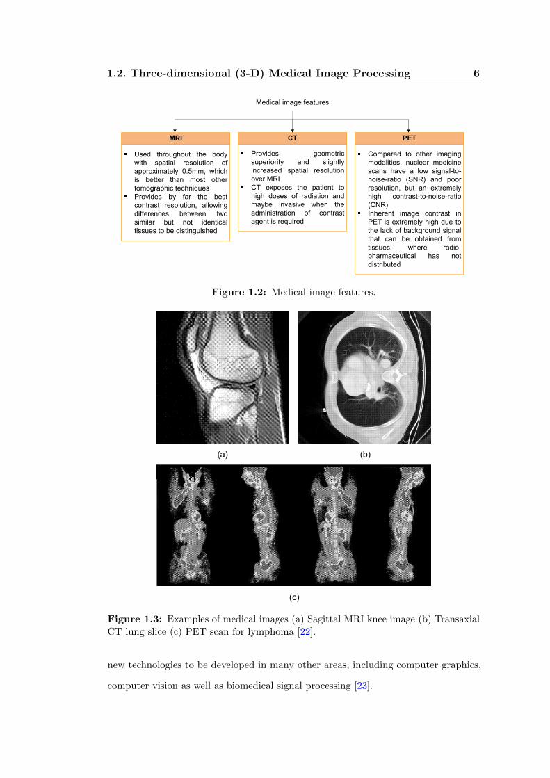
In contrast to general image processing analysis that converts an image signal
into a physical image, various medical imaging modalities have been shown to be
useful for patient diagnosis [5]. An overview of MRI, CT and PET image features is
given in Figure 1.2, whilst some examples of MRI, CT and PET images are depicted
in Figure 1.3(a) – (c).
To date, modern medical imaging technologies are capable of generating high-
resolution 3-D images, and consequently, make medical image analysis tasks at least
one-dimension more compute-intensive than standard planar 2-D images [6]. In
brief, the higher computational cost appears in medical imaging analysis, introduces
1.2. Three-dimensional (3-D) Medical Image Processing 6
Medical image features
Used throughout the body
with spatial resolution of
approximately 0.5mm, which
is better than most other
tomographic techniques
Provides by far the best
contrast resolution, allowing
differences between two
similar but not identical
tissues to be distinguished
MRI
Provides geometric
superiority and slightly
increased spatial resolution
over MRI
CT exposes the patient to
high doses of radiation and
maybe invasive when the
administration of contrast
agent is required
CT
Compared to other imaging
modalities, nuclear medicine
scans have a low signal-to-
noise-ratio (SNR) and poor
resolution, but an extremely
high contrast-to-noise-ratio
(CNR)
Inherent image contrast in
PET is extremely high due to
the lack of background signal
that can be obtained from
tissues, where radio-
pharmaceutical has not
distributed
PET
Figure 1.2: Medical image features.
(a) (b)
(c)
Figure 1.3: Examples of medical images (a) Sagittal MRI knee image (b) TransaxialCT lung slice (c) PET scan for lymphoma [22].
new technologies to be developed in many other areas, including computer graphics,
computer vision as well as biomedical signal processing [23].
1.2. Three-dimensional (3-D) Medical Image Processing 7
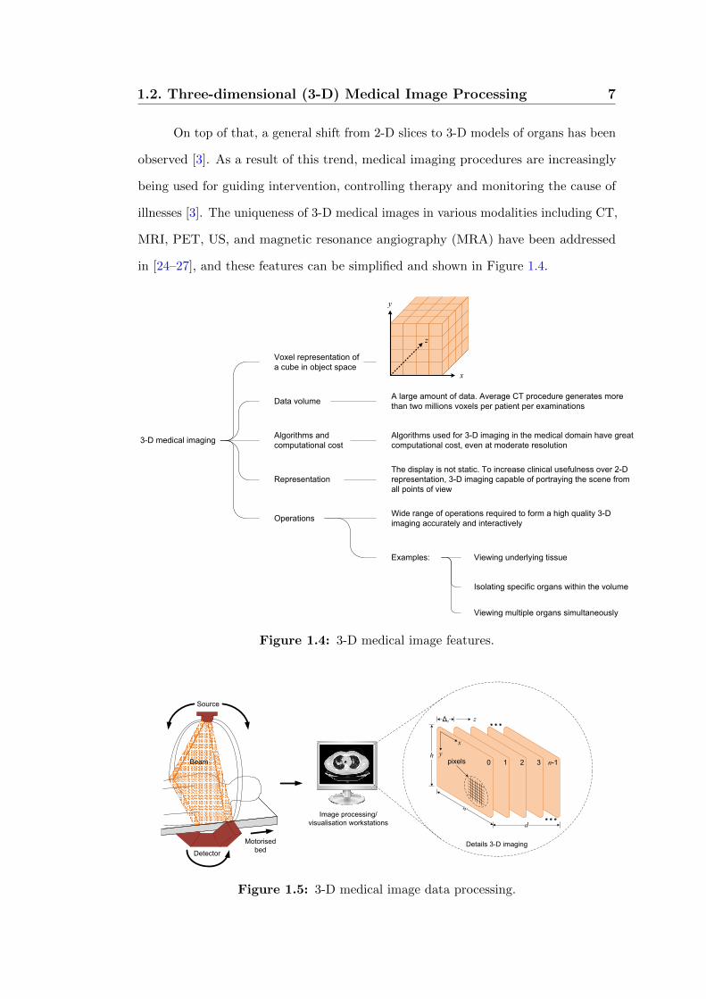
On top of that, a general shift from 2-D slices to 3-D models of organs has been
observed [3]. As a result of this trend, medical imaging procedures are increasingly
being used for guiding intervention, controlling therapy and monitoring the cause of
illnesses [3]. The uniqueness of 3-D medical images in various modalities including CT,
MRI, PET, US, and magnetic resonance angiography (MRA) have been addressed
in [24–27], and these features can be simplified and shown in Figure 1.4.
Voxel representation of
a cube in object space
y
x
z
A large amount of data. Average CT procedure generates more
than two millions voxels per patient per examinationsData volume
Algorithms and
computational cost
Algorithms used for 3-D imaging in the medical domain have great
computational cost, even at moderate resolution
Representation
The display is not static. To increase clinical usefulness over 2-D
representation, 3-D imaging capable of portraying the scene from
all points of view
OperationsWide range of operations required to form a high quality 3-D
imaging accurately and interactively
Examples: Viewing underlying tissue
Isolating specific organs within the volume
Viewing multiple organs simultaneously
3-D medical imaging
Figure 1.4: 3-D medical image features.
Source
Beam
Motorised
bedDetector
Image processing/
visualisation workstations
∆z z
x
yh
w
d
0 1 2 3 n-1pixels
Details 3-D imaging
Figure 1.5: 3-D medical image data processing.

1.2. Three-dimensional (3-D) Medical Image Processing 8
In 3-D medical imaging modalities, the data produced usually consists
of a number of parallel slices for the body. As illustrated in Figure 1.5, most
generated medical volumes acquire one slice at a time, with the patient moved
along on a motorised bed between each slice. The resulting data set comprises n-slices
and each containing w × h pixels. The slices are separated by a distance ∆z pixels,
where ∆z is usually greater than one. The data is therefore, anisotropic, with inferior
resolution perpendicular to the slices than within them. The depth d of the data set
is (n− 1)∆z.
To paint a comprehensive picture of the central issues in 3-D medical image
processing, several survey papers have been collected and analysed, then illustrated as
a time line in Figure 1.6.
1988 1991 2000 2002 2003 2006
Orphanoudakis [29]
Coatrieux et al. [30]
1990
Stytz et al. [26]
“Supercomputing in
medical computing”
“Future trends in 3-D
medical imaging”
“Three-dimensional
medical imaging:
algorithms and computer
systems”
1998
Maintz & Viergever [31]
“A survey of medical
image registration”
Duncan & Ayache [21]
“Medical image analysis:
progress over two
decades and the
challenges ahead”
2010
Sakas [3]
“Trends in medical
imaging: from 2D to 3D”
Ritman [28]
“Evolution of medical
tomographic imaging -
as seen from
a Darwinian perspective”
Shams et al. [6]
“A survey of medical
image registration on
multicore and the GPU”
Muraki & Kita [23]
“A survey of medical
applications of 3-D
image
analysis and computer
graphics”
Figure 1.6: Survey on medical image processing.
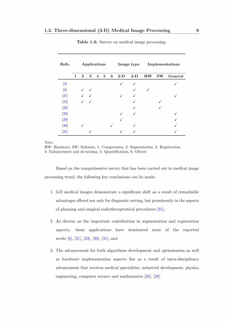
Consequently, Table 1.3 illustrates the classification of all these works based on
the following points:
1. Medical image processing applications – compression, segmentation, registration,
enhancement and de-noising, quantification;
2. System implementation – hardware design and development, software simulation
or algorithm development and optimisation; and
3. Types of images – 2-D or 3-D.
1.2. Three-dimensional (3-D) Medical Image Processing 9
Table 1.3: Survey on medical image processing.
Refs. Applications Image type Implementations
1 2 3 4 5 6 2-D 3-D HW SW General
[3] X X X
[6] X X X X
[21] X X X X X
[23] X X X X
[26] X X
[28] X X X
[29] X X
[30] X X X X
[31] X X X X
Note:HW: Hardware, SW: Software, 1: Compression, 2: Segmentation, 3: Registration4: Enhancement and de-noising, 5: Quantification, 6: Others
Based on the comprehensive survey that has been carried out in medical image
processing trend, the following key conclusions can be made:
1. 3-D medical images demonstrate a significant shift as a result of remarkable
advantages offered not only for diagnostic setting, but prominently in the aspects
of planning and surgical radiotherapeutical procedures [31];
2. As diverse as the important contribution in segmentation and registration
aspects, these applications have dominated most of the reported
works [6], [21], [23], [30], [31]; and
3. The advancement for both algorithms development and optimisation as well
as hardware implementation aspects lies as a result of intra-disciplinary
advancement that involves medical specialities, industrial development, physics,
engineering, computer science and mathematics [26], [28].

1.3. High-Performance Solutions for Medical Image ProcessingApplications 10
A close examination of the algorithms used in real-time medical image processing
applications reveals that many of the fundamental actions involve matrix or vector
operations [5]. Most of these operations are matrix transforms including fast Fourier
transform (FFT), discrete wavelet transform (DWT) and some recently developed
transforms such as finite Radon, curvelet and ridgelet transforms which are used in
2-D or 3-D medical imaging [32].
Unfortunately, computational complexity for the matrix transform algorithms
is in the order from O(N × logN) for FFT to O(N2 × J) for the curvelet transform
(where N is the transform size and J is the maximum transform resolution level)
are computationally intensive for large size problems. For that reason, efficient
implementation for these operations are of interest not only because matrix transforms
are important in their own right, but because they automatically lead to efficient
solutions to deal with massive medical volumes [19].
As diverse as the spectrum that has been explained, hardware acceleration for
medical image processing has attracted much attention in research and development. In
the following section, discussions on the potential hardware platforms for consideration
in this research study are given.
1.3 High-Performance Solutions for Medical
Image Processing Applications
One of the primary methods in conventional computing for the execution of image
and signal processing algorithms is the use of GPPs. Processors execute a set of
instructions to perform a computation. By changing the software instructions, the
functionality of the system is altered without the hardware modification.
However, this flexibility does not contribute for significant overall performance.
The processor must read each instruction from memory, decode its meaning and only
then execute it. This result in a high execution overhead for each individual operation.

1.3. High-Performance Solutions for Medical Image ProcessingApplications 11
Additionally, the set of instructions that may be used by a program is determined at
the fabrication time of the processor. Any other operations that are to be implemented
must be built out of existing instructions.
To achieve high-performance, image and signal processing applications
implementation have moved away from the traditional approach of general-purpose
computing towards systems containing specialist architectural support. A lot of
research has been carried out on architectural support including DSPs and special
purpose hardware [11]. An overview of possible platforms is given in the following
subsections.
1.3.1 Digital Signal Processor (DSP)
One method of increasing the performance of GPP is to attach a specialised processing
unit in the form of DSP. As illustrated in Figure 1.7, DSP has features that accelerate its
capability for high-performance, repetitive and numerically intensive task applications.
Various configurations
of on-chip memory
and peripherals
tailored for DSP
applications
Irregular instruction
sets
Single-cycle, multiply-
accumulate capability
Specialised execution
control
Capability Control
Configurations Instruction sets
Features that accelerate performance in DSP applications
Figure 1.7: DSPs features for performance accelerations.
High performance DSPs often have two multipliers that enable two multiply-
accumulate operations per instruction cycle. Moreover, DSPs generally feature
multiple-access memory architectures that enable DSPs to complete several accesses
to memory in a single instruction cycle. Furthermore, DSPs usually provide a loop
instruction that allows tight loops to be repeated without spending any instruction

1.3. High-Performance Solutions for Medical Image ProcessingApplications 12
cycles for updating and testing the loop counter or for jumping back to the top of the
loop.
DSPs generally allow several operations to be encoded in a single instruction.
For example, a processor that uses 32-bits instructions may encode two additions and
multiplications, and four 16-bits data moves into a single instruction. Besides, DSP
instruction sets allow a data move to be performed in parallel with an arithmetic
operation. GPPs, in contrast, usually specify a single operation per instruction.
It is worth mentioning that the DSPs are also equipped with embedded fused
multiply/add which can be used for orthogonal transforms implementations such as
discrete cosine transform (DCT), discrete Hartley transform (DHT) as well as others
computation-intensive DSP functions like convolution, interpolation and adaptive
filtering [33]. As a result, DSPs have been successfully used in a wide range of image
processing applications [34–39].
1.3.2 Special Purpose Application Specific Integrated
Circuit (ASIC) Hardware
ASICs give better performance for particular applications, and they are designed
specifically to perform a specific computation. Owing to this feature, they efficiently
perform the given task according to the application’s design specification which may
be to optimise for one or more of design flexibility, performance, power consumption
and area [40–42]. However, after fabrication the circuit is unable to be altered. This
forces a redesign and a refabrication of any part of the chip which requires modification.
This is an expensive process, especially when one considers the difficulties in replacing
ASICs in a large deployed system [11]. The main disadvantages of this approach can
be summarised as shown in Figure 1.8.
A new breed of ASIC products, called “structured ASIC”, can reduce the
expenses by more than 90% for derivative chips, and speed up time-to-market [43].
The underlying concept behind structured ASICs is fairly simple. Although there

1.3. High-Performance Solutions for Medical Image ProcessingApplications 13
Disadvantages of ASICs approach
Special purpose hardware
has a long development time,
from design through
simulation and fabrication
Development time
It can also be expensive if it
is a one-off solution or if the
volume required cannot
justify its fabrication costs
Cost
Once this special purpose
hardware is built, it is not
possible to change the
hardware to accommodate
slightly different needs
A new hardware is usually
required for each new
algorithm
Flexibility
Figure 1.8: Main disadvantages of ASICs.
are a wide variety of alternative architectures, they are all based on a fundamental
element called a “tile” by some or a “module” by others. This tile contains a small
amount of generic logic implemented either as gates and/or multiplexers and/or a LUT.
Depending on the particular architecture, the tile may contain one or more registers
and possibly a very small amount of local random access memory (RAM). An array
of these tiles is then pre-fabricated across the face of the chip [43], [44].
Structured ASICs also typically contain additional pre-fabricated elements,
which may include configurable general-purpose input/output (I/O), microprocessor
cores, gigabit transceivers and embedded block RAM. When compared with standard
cell-based ASICs, structured ASICs offer shorter turnaround time, and require less
cost for future functional changes. Structured ASIC technology is especially suitable
for platform ASIC designs that have integrated most of the intellectual property (IP)
blocks and leave some space for custom changes [45].
1.3.3 Graphical Processing Unit (GPU)
In these days, GPU computing has gained significant momentum and has evolved
into an established research area. Hardware vendors have recognised the benefits of
GPU computing and have provided high-level programming environments to express
parallelism more efficiently [46]. In comparison with central processing units (CPUs)
as shown in Figure 1.9(a) and (b), the GPUs architecture is to dedicate as much silicon

1.3. High-Performance Solutions for Medical Image ProcessingApplications 14
area as possible to arithmetic logic units (ALUs). By eliminating all the scheduling
logic and caches, GPUs can exploit instruction-level parallelism, and hence reduce
memory latency in CPUs [47].
CPU
Regs. ALU
Local cache
Out-of-order
scheduler
CPU
Shared cache
CPU
CPU
CPU
DDR memory
Regs. ALU
Regs.
Regs.
Regs.
ALU
ALU
ALU
Regs. RAM
Regs.
Regs.
Regs.
RAM
RAM
RAM
Dynamic
arbitration
Thread-aware scheduler
CPU
CPU
CPU
CPU
CPU
CPU
...
CPU
Dynamic arbitration
DDR
bank
DDR
bank
DDR
bank
DDR
bank
(a) (b)
Figure 1.9: Architecture comparison (a) CPU (b) GPU [47].
The popular association of GPUs is with accelerating graphics, but the new
architectures from manufactures such as NVIDIA corporation and ATI are capable of
performing general-purpose computing. There are two approaches [13] for general-
purpose computing using GPU: to pose the problem as a graphic problem and solve
it using a graphic language such as OpenGL or DirectX GPU programming, or to
program the GPU directly.
Even GPUs as commodity computer graphics chips are probably todays most
powerful computational hardware with cost, the main limitations and difficulties [48]
of this platform can be simplified as follows:
1. Applications:
The increasing flexibility of GPUs, coupled with some ingenious uses of
that flexibility by general-purpose computation on graphics processing units
(GPGPU) developers, has enabled many applications outside the original narrow

1.3. High-Performance Solutions for Medical Image ProcessingApplications 15
tasks for which GPUs were originally designed, but many applications still exist
for which GPUs are not well suited;
2. Computing constructs:
The lack of integers and associated operations such as bit-shifts and bit-
wise logical operations (AND, OR, XOR, NOT) makes GPUs unsuitable for many
computationally intense tasks. Moreover, the lack of double precision prevents
GPUs from being applicable to many very large-scale computational science
problems; and
3. Non-graphics tasks:
The GPU uses an unusual programming model, so effective programming is
not simply a matter of learning a new language. Indeed, the computation must
be recasting into graphics terms by a programmer familiar with the design,
limitations, and evolution of the underlying hardware.
1.3.4 Reconfigurable Hardware (RH): A Review of Field
Programmable Gate Array (FPGA)
The recent advances in RH are for the most part derived from the technologies
developed for FPGAs in the mid 1980s [13]. FPGAs were originally created to serve as
a hybrid device between programmable arrays logics (PALs) and mask programmable
gate arrays (MPGAs). Like PALs, FPGAs are fully electrically programmable,
meaning that the physical design costs are amortised over multiple application circuit
implementations, and the hardware can be customised nearly instantaneously. Like
MPGAs, they can implement very complex computations on a single chip, since it
consists of an array of pre-fabricated transistors that can be customised during chip
fabrication [15]. MPGAs allow for user’s customisation by connecting the transistors
with custom wires.

1.3. High-Performance Solutions for Medical Image ProcessingApplications 16
Because of these features, FPGAs have been viewed primarily as glue logic
replacement and a rapid prototyping vehicle. However, the flexibility, capacity
and performance of these devices have opened up completely new avenues in high-
performance computation, forming the basis of reconfigurable computing [11], [49].
The early FPGA devices from Xilinx, Altera and others provided relatively little
logic, but later generations provided enough logic for researchers to consider FPGAs
for direct implementation of computational algorithms in reconfigurable logic devices.
The densities of todays FPGAs have exceeded 150,000 6-input LUTs per device and
some have developed into devices that can be used to build complete systems on
a programmable chip (SoPC), providing such specialised features as DSP blocks, multi-
gigabit serial I/O, embedded microprocessors and embedded static RAM (SRAM)
blocks of various sizes.
Field Programmable Gate Array (FPGA) Structure
The basic architecture of FPGAs consists of three components: logic blocks, routing and
I/O blocks. Generally, FPGAs consist of an array of programmable logic blocks that
can be interconnected to each other as well as to the programmable I/O blocks through
some sort of programmable routing architecture. To be more specific, Figure 1.10
provides an overview diagram of Xilinx’s FPGA architecture.
A Basic Logic Block
As shown in Figure 1.10, a typical FPGA has a logic block with one or more 4-input
LUT, optional D flip-flop (DFF) and some form of fast carry logic. The LUTs allow
any function to be implemented, providing generic logic. The DFF can be used for
pipelining, registers, state holding functions for finite state machines, or any other
situation where clocking is required. The fast carry logic is a special resource provided
in the cell to speed up carry-based computations, such as addition, parity, wide logical
AND operations and other functions.

1.3. High-Performance Solutions for Medical Image ProcessingApplications 17
4-LUTFF
1
0
Latch
O/PI/P
Configuration bitstream
Configuration logic blocks (CLBs)
Programmable
interconnect
Memory blocksDigital clock
management (DCM)
Input/Output blocks
(IOBs)
Figure 1.10: Xilinx’s FPGA structure with internal blocks.
Routing
Most FPGA architectures organise their routing structures as a relatively smooth
sea of routing resources, allowing fast and efficient communication along the rows
and columns of logic blocks [49]. The logic blocks are embedded in a general routing
structure, with input and output signals attaching to the routing fabric through
connection blocks as shown in Figure 1.10.
Connection Blocks
The connection blocks provide programmable multiplexers, selecting which of the
signals in the given routing channel will be connected to the logic block’s terminals.
These blocks also connect shorter local wires to longer distance routing resources.
Signals flow from the logic block into the connection block and then along longer wires
within the routing channels [49].

1.4. Design and Implementation Strategies 18
Switch Boxes
At the switch boxes, there are connections between the horizontal and vertical routing
resources to allow signals to change their routing direction. Once the signal has
traversed through routing resources and intervening switch boxes, it arrives at the
destination logic block through one of its local connection blocks.
In this manner, relatively arbitrary interconnections can be achieved between
the logic blocks in the system. Whilst the routing architecture of an FPGA is typically
quite complex, the connection blocks and switch boxes surrounding a single logic block
typically have thousands of programming points. They are designed to be able to
support fairly arbitrary interconnection patterns [49]. A detailed descriptions of the
FPGA devices that have been used in this research are presented in Appendix A.
1.4 Design and Implementation Strategies
In this research study, three design and implementation strategies have been used
as illustrated in Figure 1.11. The design flows for these strategies are presented in
Figure 1.12.
In Chapter 3, very-high-speed integrated circuit hardware description language
(VHDL) and partial reconfiguration tools have been used to implement 3-D Haar
wavelet transform (HWT). Four main stages involved: design entry, synthesis,
implementation and programming. In case of partial reconfiguration, design
partitioning, floor planning and budgeting are the main processes involved.
To deal with medical image de-noising as well as to evaluate the performance of
finite Radon transform (FRAT), Xilinx AccelDSP tool has been utilised in Chapter 4.
The design and implementation begin with an examination of floating point model
followed with fixed point and register-transfer level (RTL) generation as well as
synthesise and implementation processes.

1.5. Motivation and Research Objectives 19
Finally, VHDL has been fully used again to execute the design and
implementation of 3-D compression system in Chapter 5. A detailed explanation for
each tool used in this study are presented in Appendix B, C and D.
Design description
VHDL
VHDLXilinx partial
reconfigurationXilinx AccelDSP
FPGA rapid prototyping board
(a) (b) (c)
Figure 1.11: Generic design and implementation strategies.
1.5 Motivation and Research Objectives
FPGAs is an extremely powerful tool for several reasons. First and foremost, it allows
for truly parallel computations to take place in a circuit. Many modern GPPs and
operating systems can emulate parallelism by switching tasks very rapidly. Having
operations occur in a parallel fashion results in a much faster overall processing time.
This is the case even though the clock speed of the FPGA is lower than the GPPs.
With the availability of advances embedded resources on recent FPGAs devices
such as soft cores, dedicated logic and block multipliers, FPGAs are being increasingly
deployed in computationally intensive application areas. Moreover, prototyping is
also a compelling reason to use FPGAs in the initial design phase. The description of
a system can be written and actual hardware can be created to test, instead of simply

1.5. Motivation and Research Objectives 20
Examine the MATLAB
floating point model
(m-file)
Verify
Verify
Simulation
Verify
Fixed point model
RTL model
(VHDL/Verilog)
Gate level netlist
Bitstream and
simulation files
Generate fixed point
Generate RTL
Synthesise RTL
Implementation
Partition the system into modules
Define static modules and
reconfigurable modules
Decide the number of partial
reconfiguration regions
Decide partial reconfiguration
region sizes, shapes and locations
Map modules to partial
reconfiguration regions
Define partial reconfiguration region
interfaces, instantiate slice macros
for partial reconfiguration regions
interfaces
Design partitioning Design floor planning and budgeting
Design entry
Create project
VHDL
Enter constraints
Functional
simulation
Analyse timing
CoreGen
Select target
Synthesise
Optimise
Add source
Check syntax
Implementation
Map
Place and route
Create bitstream
Analyse timing
Functional
simulation
Analyse timing
Programming
B
B
Synthesise
VHDL
Partial
reconfiguration
AccelDSP
(a)
(b)
(c)
Fig
ure
1.1
2:
Ove
rall
des
ign
flow
.

1.5. Motivation and Research Objectives 21
relying on simulators inside of design. Moreover, the design flexibility available on
FPGAs also allows a design to be thoroughly tested and debugged before an ASIC is
created, saving on production costs.
FPGAs are everywhere. Companies use them on development boards to help
refine new chip designs. Students use them in the laboratory to run experiments.
Companies and universities are using them in cutting-edge research on topics ranging
from programming technology to real-time systems. The parts themselves are getting
so inexpensive that some companies do not even fabricate an ASIC, they simply
include the FPGA in their final product.
With the emergence of such reconfigurable hardware, it is not surprising that
there has been a considerable amount of research into the use of FPGAs to increase
the performance of a wide range of computationally intensive applications. One
such application that could greatly benefit from the advantages offered by FPGAs is
medical image processing. The regular nature of the complex computations performed
repeatedly within medical image processing operations are well suited to a hardware-
based implementation using FPGAs.
The application of 3-D medical image processing such as compression and
de-noising uses several building blocks for its computationally intensive algorithms to
perform matrix transformation operations. Moreover, complexity in addressing and
accessing large medical volumes data to be processed have resulted in vast challenges
from a hardware implementation point of view.
In order to cope with these issues, FPGAs with efficient reconfigurability
techniques should be employed to meet the requirements of these applications in
terms of speed, size (area), power consumption and throughput. Dynamic partial
reconfiguration (DPR) is a promising technique for reducing the hardware required
for implementing an efficient design for 3-D medical image processing application as
well as improving the performance of the system. With this technique, the design can
be divided into sub-designs that fit into the available hardware resources and can be
1.6. Overall Contribution 22
uploaded into the reconfigurable hardware when needed [50].
The general goal of this research is concerned with the design and implementation
of efficient reconfigurable architectures for 3-D medical image processing, with more
emphasis on compression systems and image de-noising. Based on the potential
significant contributions in this area, the main objectives of the work presented in this
research can be broadly summarised as follows:
1. To design and implement efficiently 3-D HWT architecture using DPR –
efficiently can be used as a transform block in the proposed compression system;
2. To design and implement efficiently the finite Radon transform (FRAT) – to be
applied for medical image de-noising in pre-processing stage; and
3. To design and implement the 3-D medical image compression system using
context-based adaptive variable length coding (CAVLC) – to experimentally
demonstrate the whole compression system functionality.
1.6 Overall Contribution
To support the research objectives that have been listed in Section 1.5, Figure 1.13
shows the overall research strategies with potential contributions to be achieved in
this research. For the 3-D compression system, analysis of the transform block as
well as utilisation of CAVLC are expecting to generate promising outcomes. In terms
of transform block, an examination of different transform filters is anticipated to
demonstrate a significant contribution. Moreover, by implementing DPR technique,
better performance in terms of area, power consumption and maximum frequency is
predicted. Furthermore, an evaluation of the FRAT’s capability to deal with image
de-noising is presumed to exhibit another noteworthy analysis and discussion.

1.6. Overall Contribution 23F
PG
A
Sta
tic a
rea
Blo
ck R
AM
s
Da
ta f
etc
h
unit
1
3 T1
1-D
HW
T
3 T22
1-D
HW
T
2
2 4
1-D
HW
TF
PG
A
Re
config
ura
ble
are
a
Tra
nspose
Sta
tic a
rea
Blo
ck R
AM
s
Data
fetc
h
un
it
1-D
HW
T
Re
config
ura
ble
are
a
1
2
3
4
(a)
Withou
t dyna
mic
pa
rtia
l re
con
figura
tion
(b)
With
dynam
ic p
art
ial re
configu
ratio
n
Image
de
-no
isin
g
Com
pre
ssio
n
syste
ms
Input:
Med
ical
images
Outp
ut:
Bitstr
ea
m
Fin
ite R
adon
transfo
rmT
hre
shold
ing
Invers
e F
inite
Radon tra
nsfo
rm
RE
WR
EW
12
31
23
...
...
...
(c)
BR
AM
-based
RE
W RE
W RE
W ...
...
...
(a)
Seque
ntial
(b)
Pip
elin
ed
Mo
de
Mo
de
3-D
Tra
nsfo
rm
(IT
/DW
T)
Qu
antisatio
n/
se
lectio
nC
AV
LC
Input:
Medic
al
images
Outp
ut:
Bitstr
eam
Buff
ers
Buffe
rsB
uffers
(b)
Butte
rfly
arc
hitectu
re
of 1-D
IT
x
y
z
Sub-im
ages [I]z
Su
b-im
ages [1]
Sub-im
ages [I]0
Re
ad
, C
om
pu
te B
RA
M1,
Wri
te B
RA
M2
Re
ad
, C
om
pu
te B
RA
M2,
Wri
te B
RA
M1
...
Re
ad
, C
om
pu
te B
RA
M1,
Wri
te B
RA
M2
Re
ad
, C
om
pu
te B
RA
M2,
Wri
te B
RA
M1
Re
ad
, C
om
pu
te B
RA
M1,
Wri
te B
RA
M2
Re
ad
, C
om
pu
te B
RA
M2,
Wri
te B
RA
M1
Mod
e
Chapter 4: FPGA-based Implementation of FRAT for
medical image de-noising
Chapter 3: Efficient Architectures of 3-D HWT using DPR
X[0]
X[1]
X[2]
X[3]
Y[0]
Y[2]
Y[1]
Y[3]
-1
-2
2
-1
Chapter 5: FPGA Implementation of a Compression System for
3-D Medical Images using CAVLC
(c)
CA
VLC
arc
hitectu
re
TrailingOnes
TotalZeros
EncodeLevel
Encode
RunZeros
Variable
extr
action
CoeffToken B
itstr
eam
Genera
tion
& S
torin
g
16
x8 b
its m
em
ory
TotalCoeff
TrailingOnes
NB
TrailingOnes
NB
TrailingOnes
TotalCoeff
TotalZeros
TotalCoeff
TrailingOnes
NB
Non-zeros coeff
Coeff
Coeff
Sym
bols
Enco
der
16
x8
bits m
em
ory
(a)
A s
imple
lifting-b
ase
d p
erf
ect
reconstr
uctio
n e
ncode
r
Z-1
↓Ɖ
↓
P1
RU1
RƉ
X
+
+
-
+X0
X1
X’ 1
X’ 0
12
12
12
1 2 1 2 1 2
-1
Fig
ure
1.1
3:
Ove
rall
rese
arch
app
roac
hes
and
contr
ibu
tion
s.
1.7. Thesis Organisation 24
1.7 Thesis Organisation
The structure of the remaining thesis is as follows. Chapter 2 takes a closer look
at the most recent architectures and systems for 3-D medical image compression,
reconfigurable architectures for DWT, FRAT, CAVLC as well as the DPR method.
Design and implementation of an efficient pipelined 3-D HWT architecture using
DPR are presented in Chapter 3. A comparative study for the impact of transform
sizes of architectures performance is also addressed.
In Chapter 4, medical image de-noising using the FRAT is given. Three design
strategies and analysis of FRAT’s performance for noise reduction in medical images
is also discussed.
To give a complete overview of this research study, Chapter 5 describes the
implementation of 3-D medical image compression system using CAVLC. In this
chapter, an evaluation of 3-D integer transform (IT) and DWT have been carried out
and discussion on the CAVLC architecture is also reported.
In Chapter 6, concluding remarks and possible refinement of the current research
are highlighted. Finally, possible future research directions in the field of design and
implementation of 3-D medical image compression systems is presented.

Bibliography
[1] H. Lee, Y. Kim, A. H. Rowberg, and E. A. Riskin, “Statistical distributions of
DCT coefficients and their application to an interframe compression algorithm
for 3-D medical images,” Medical Imaging, IEEE Transactions on, vol. 12, no. 3,
pp. 478–485, Sept. 1993.
[2] [Online], “Accessed 20 June 2009,” http://info.cancerresearchuk.org/cancerstats/
incidence/index.htm.
[3] G. Sakas, “Trends in medical imaging: from 2D to 3D,” Computers & Graphics,
vol. 26, no. 4, pp. 577–587, 2002.
[4] M. J. Zukoski, T. Boult, and T. Iyriboz, “A novel approach to medical image
compression,” Int. J. Bioinformatics Research and Applications, vol. 2, no. 1,
pp. 89–103, 2006.
[5] D. W. G. Montgomery, “Multiscale compression and segmentation of volumetric
oncological PET imagery,” PhD Thesis, School of Computer Science, The
Queen’s University of Belfast, 2006.
[6] R. Shams, P. Sadeghi, R. Kennedy, and R. Hartley, “A survey of medical image
registration on multicore and the GPU,” Signal Processing Magazine, IEEE,
vol. 27, no. 2, pp. 50–60, Mar. 2010.
[7] J. Wang and H. K. Huang, “Three-dimensional medical image compression using
a wavelet transform with parallel computing,” Medical Imaging 1995: Image
Display, vol. 2431, no. 1, pp. 162–172, 1995.
163

BIBLIOGRAPHY 164
[8] J. Jyotheswar and S. Mahapatra, “Efficient FPGA implementation of DWT
and modified SPIHT for lossless image compression,” J. Syst. Archit., vol. 53,
no. 7, pp. 369–378, 2007.
[9] M. Jiang and D. Crookes, “Area-efficient high-speed 3D DWT processor
architecture,” IEE Electronics Letter, vol. 43, pp. 502–503, 2007.
[10] ——, “FPGA implementation of 3D discrete wavelet transform for real-time
medical imaging,” in Circuit Theory and Design (ECCTD 2007), Proc. 18th
European Conf. on, Seville, Spain, 2007, pp. 519–522.
[11] P. Dang, “VLSI architecture for real-time image and video processing systems,”
Journal of Real-Time Image Processing, vol. 1, pp. 57–62, Oct. 2006.
[12] M. Papadonikolakis, C. S. Bouganis, and G. Constantinides, “Performance
comparison of GPU and FPGA architectures for the SVM training problem,” in
Field-Programmable Technology, 2009 (FPT 2009), Proceedings of International
Conference on, Dec. 2009, pp. 388–391.
[13] M. L. Stokes, “A brief look at FPGAs, GPUs and cell processors,” Journal of
The International Test and Evaluation Association (ITEA), pp. 9–11, June/July
2007.
[14] T. Todman, G. Constantinides, S. Wilton, O. Mencer, W. Luk, and P. Cheung,
“Reconfigurable computing: architectures and design methods,” Computers and
Digital Techniques, IEE Proceedings, vol. 152, no. 2, pp. 193–207, Mar. 2005.
[15] S. Brown and J. Rose, “Architecture of FPGAs and CPLDs: A tutorial,” IEEE
Design and Test of Computers, vol. 13, no. 2, pp. 42–57, 1996.
[16] [Online], “Accessed 20 Jan 2008,” http://www.xilinx.com/publications/archives/
xcell/Xcell-customer-innovation-2010.pdf.
[17] C. Maxfield, The Design Warrior’s Guide to FPGAs: Devices, Tools and Flows.
Elsevier, 2004.

BIBLIOGRAPHY 165
[18] F. Bensaali, “Accelerating matrix product on reconfigurable hardware for image
processing applications,” PhD Thesis, School of Computer Science, The Queen’s
University of Belfast, 2005.
[19] I. S. Uzun, “Design and FPGA implementation of matrix transforms for image
and video processing,” PhD Thesis, School of Computer Science, The Queen’s
University of Belfast, 2006.
[20] S. Chandrasekaran, “Efficient FPGA implementation and power modelling of
image and signal processing IP cores,” PhD Thesis, School of Engineering and
Design, Brunel University, West London, 2007.
[21] J. S. Duncan and N. Ayache, “Medical image analysis: progress over two decades
and the challenges ahead,” Pattern Analysis and Machine Intelligence, IEEE
Transactions on, vol. 22, no. 1, pp. 85–106, Jan. 2000.
[22] [Online], “Accessed 10 Feb. 2009,” http://www.rsna.org.
[23] S. Muraki and Y. Kita, “A survey of medical applications of 3D image analysis
and computer graphics,” Syst. Comput. Japan, vol. 37, no. 1, pp. 13–46, 2006.
[24] R. S. Lazebnik and T. S. Desser, “Clinical 3D ultrasound imaging: beyond
obstetrical applications,” Diagnostic Imaging: Continuing Medical Education,
pp. 1–6, 2009.
[25] A. Kurjak, B. Miskovic, W. Andonotopo, M. Stanojevic, G. Azumendi, and
H. Vrcic, “How useful is 3D and 4D ultrasound in perinatal medicine?”
J. Perinat. Med., vol. 35, pp. 10–27, 2007.
[26] M. R. Stytz, G. Frieder, and O. Frieder, “Three-dimensional medical imaging:
algorithms and computer systems,” ACM Comput. Surv., vol. 23, no. 4, pp.
421–499, 1991.

BIBLIOGRAPHY 166
[27] G. D. Michailidis, P. Papageorgiou, and D. L. Economides, “Assessment of fetal
anatomy in the first trimester using two- and three-dimensional ultrasound,”
The British Journal of Radiology, vol. 75, no. 891, pp. 215–219, 2002.
[28] E. L. Ritman, “Evolution of medical tomographic imaging - as seen from
a Darwinian perspective,” Proceedings of the IEEE, vol. 91, no. 10, pp. 1483–
1491, Oct. 2003.
[29] S. C. Orphanoudakis, “Supercomputing in medical imaging,” Engineering in
Medicine and Biology Magazine, IEEE, vol. 7, no. 4, pp. 16–20, Dec. 1988.
[30] J. Coatrieux, C. Toumoulin, C. Hamon, and L. Luo, “Future trends in 3D
medical imaging,” Engineering in Medicine and Biology Magazine, IEEE, vol. 9,
no. 4, pp. 33–39, Dec. 1990.
[31] J. Maintz and M. A. Viergever, “A survey of medical image registration,” Medical
Image Analysis, vol. 2, no. 1, pp. 1–36, 1998.
[32] D. Z. Tian and M. H. Ha, “Applications of wavelet transform in medical image
processing,” in Machine Learning and Cybernetics, Proceedings of International
Conference on, Baoding, China, 2004, pp. 1816–1821.
[33] A. K. Rath and P. K. Meher, “Design of a merged DSP microcontroller for
embedded systems using discrete orthogonal transform,” Journal of Computer
Science, vol. 2, no. 5, pp. 388–394, 2006.
[34] A. Bensrhair, N. Chafiqui, and P. Miche, “Implementation of a 3D vision system
on DSPs TMS320C31,” Journal of Real Time Image Processing, vol. 6, no. 3,
pp. 213–221, June 2000.
[35] C. Basoglu, W. Lee, and J. O’Donnell, “The equator MAP-CA(TM)DSP: An
end-to-end broadband signal processor (TM) VLIW,” Circuits and Systems
for Video Technology, IEEE Transactions on, vol. 12, no. 8, pp. 646–659, Aug.
2002.

BIBLIOGRAPHY 167
[36] J. Furtler, K. J. Mayer, W. Krattenthaler, and I. Bajla, “SPOT: Development
tool for software pipeline optimization for VLIW-DSPs used in real-time image
processing,” Journal of Real Time Image Processing, vol. 9, no. 6, pp. 387–399,
Dec. 2003.
[37] D. Jinghong, D. Yaling, and L. Kun, “Development of image processing system
based on DSP and FPGA,” in Electronic Measurement and Instruments, 2007.
ICEMI ’07. 8th International Conference on, Aug. 2007, pp. 791–794.
[38] Y. Zou, G. Shi, Y. Jin, and Y. Zheng, “Extraocular image processing for retinal
prosthesis based on DSP,” in Nano/Micro Engineered and Molecular Systems,
2009. NEMS 2009. 4th IEEE International Conference on, 2009, pp. 563–566.
[39] K. Hang, “Real-time image acquisition and processing system design based
on DSP,” in Computer and Automation Engineering (ICCAE), 2010 The 2nd
International Conference on, vol. 4, 2010, pp. 492–496.
[40] R. Kordasiewicz and S. Shirani, “ASIC and FPGA implementations of H.264
DCT and quantization blocks,” in Image Processing, 2005. ICIP 2005. IEEE
International Conference on, vol. 3, 2005, pp. III–1020–3.
[41] L. Liu, H. Meng, and M. Zhang, “An ASIC implementation of lifting-based
2-D discrete wavelet transform,” in Circuits and Systems, 2006. APCCAS 2006.
IEEE Asia Pacific Conference on, 2006, pp. 271–274.
[42] S. Mittal, Z. Khan, and M. Srinivas, “Area efficient high speed architecture
of Bruun’s FFT for software defined radio,” in Global Telecommunications
Conference, 2007. GLOBECOM ’07. IEEE, 2007, pp. 3118–3122.
[43] Y. W. Tsai, K. C. Wu, H. H. Tung, and R. B. Lin, “Using structured ASIC to
improve design productivity,” in Integrated Circuits, ISIC ’09. Proceedings of
the 2009 12th International Symposium on, 2009, pp. 25–28.

BIBLIOGRAPHY 168
[44] H. K. Phoon, M. Yap, and C. K. Chai, “A highly compatible architecture
design for optimum FPGA to structured-ASIC migration,” in Semiconductor
Electronics, 2006. ICSE ’06. IEEE International Conference on, Oct. 2006, pp.
506–510.
[45] B. Zahiri, “Structured ASICs: Opportunities and challenges,” in Computer
Design, Proceedings of the International Conference on, Oct. 2003, pp. 404–409.
[46] D. Gddeke, “Fast and accurate finite-element multigrid solvers for PDE
simulations on GPU clusters,” PhD Thesis, Institute of Applied Mathematics,
Technical University Dortmund, 2010.
[47] D. B. Thomas, L. Howes, and W. Luk, “A comparison of CPUs, GPUs,
FPGAs, and massively parallel processor arrays for random number generation,”
in Field programmable gate arrays FPGA ’09, Proceeding of the ACM/SIGDA
international symposium on, 2009, pp. 63–72.
[48] J. D. Owens, D. Luebke, N. Govindaraju, M. Harris, J. Krger, A. E. Lefohn, and
T. J. Purcell, “A survey of general-purpose computation on graphics hardware,”
Computer Graphics Forum, vol. 26, no. 1, pp. 80–113, 2007.
[49] K. Compton and S. Hauck, “Reconfigurable computing: A survey of systems
and software,” ACM Comput. Surv., vol. 34, no. 2, pp. 171–210, June 2002.
[50] A. Ahmad, B. Krill, A. Amira, and H. Rabah, “Efficient architectures for 3D
HWT using dynamic partial reconfiguration,” Journal of Systems Architecture,
vol. 56, no. 8, pp. 305–316, Aug. 2010.
[51] P. C. Cosman, R. M. Gray, and R. A. Olshen, “Evaluating quality of compressed
medical images: SNR, subjective rating, and diagnostic accuracy,” Proceedings
of the IEEE, vol. 82, no. 6, pp. 919–932, Jun. 1994.
[52] S. Ghrare, M. Ali, M. Ismail, and K. Jumari, “Diagnostic quality of compressed
medical images: Objective and subjective evaluation,” in Modeling Simulation,

BIBLIOGRAPHY 169
2008. AICMS 08. Second Asia International Conference on, May 2008, pp.
923–927.
[53] J. Wang and H. K. Huang, “Medical image compression by using three-
dimensional wavelet transformation,” Medical Imaging, IEEE Transactions
on, vol. 15, no. 4, pp. 547–554, Aug. 1996.
[54] H. B. Cattin, A. Baskurt, F. Turjman, and R. Prost, “3D medical image coding
using separable 3D wavelet decomposition and lattice vector quantization,”
Signal Processing, vol. 59, no. 2, pp. 139–153, 1997.
[55] X. Qi and J. M. Tyler, “A progressive transmission capable diagnostically lossless
compression scheme for 3D medical image sets,” Information Sciences, vol. 175,
no. 3, pp. 217–243, 2005.
[56] R. S. Sunder, C. Eswaran, and N. Sriraam, “Medical image compression using
3-D Hartley transform,” Computers in Biology and Medicine, vol. 36, no. 9, pp.
958–973, 2006.
[57] N. P. Raj and T. Venkateswarlu, “A novel approach to medical image compression
using sequential 3D DCT,” in Computational Intelligence and Multimedia
Applications, 2007. International Conference on, vol. 3, Dec. 2007, pp. 146–152.
[58] G. Bernabe, J. M. Garcia, and J. Gonzalez, “A loosy 3D wavelet transform
for high-quality compression of medical video,” The Journal of Systems and
Software, vol. 82, pp. 526–534, 2009.
[59] Y. Gaudeau and J. M. Moureaux, “Lossy compression of volumetric
medical images with 3D dead zone lattice vector quantization,” Annals of
Telecommunications, vol. 64, no. 5-6, May 2009.
[60] Z. Xiong, X. Wu, S. Cheng, and J. Hua, “Lossy-to-lossless compression of
medical volumetric data using three-dimensional integer wavelet transforms,”
Medical Imaging, IEEE Transactions on, vol. 22, no. 3, pp. 459–470, Mar. 2003.
BIBLIOGRAPHY 170
[61] M. C. Weeks, “Architectures for 3-D discrete wavelet transform,” PhD Thesis,
Department of Computer Engineering, University of Southwestern Louisiana,
Spring 1998.
[62] S. Saha, “Image compression—from DCT to wavelets: a review,” Crossroads,
vol. 6, no. 3, pp. 12–21, 2000.
[63] M. Weeks and M. Bayoumi, “3D discrete wavelet transform architectures,”
in Circuits and Systems (ISCAS ’98), Proceedings of the IEEE International
Symposium on, 1998, pp. 57–60.
[64] ——, “3-D discrete wavelet transform architectures,” Signal Process. IEEE
Trans. on, vol. 50, pp. 2050–2063, Aug. 2002.
[65] ——, “Discrete wavelet transform: Architectures, design and performance issues,”
The Journal of VLSI Sig. Process., vol. 35, pp. 155–178, 2003.
[66] B. Das and S. Banerjee, “A memory efficient 3-D DWT architecture,” in
Acoustics, Speech, and Signal Processing, Proc. Conference IEEE International
Conference on, Florida, USA, May 2002, pp. 3224–3227.
[67] S. Ismail, A. Salama, and M. Abu-ElYazee, “FPGA implementation of an
efficient 3D-WT temporal decomposition algorithm for video compression,”
in Signal Processing and Information Technology, Proc. Conference IEEE
International Symposium on, Cairo, Egypt, Dec. 2007, pp. 154–159.
[68] M. A. M. Salem, M. Appel, F. Winkler, and B. Meffert, “FPGA-based smart
camera for 3D wavelet-based image segmentation,” in Distributed Smart Cameras
(ICDSC 2008), Proc. Second ACM/IEEE Int. Conf. on, California, USA, 2008,
pp. 1–8.
[69] G. Zhang, M. Talley, W. Badawy, M. Weeks, and M. Bayoumi, “A low power
prototype for a 3-D discrete wavelet transform processor,” in Circuits and

BIBLIOGRAPHY 171
Systems (ISCAS ’99), Proc. Conference IEEE International Symposium on,
Florida, USA, May 1999, pp. 145–148.
[70] S. Chandrasekaran and A. Amira, “Novel sparse OBC based distributed
arithmetic architecture for matrix transforms,” in Circuits and Systems, 2007.
ISCAS 2007. IEEE International Symposium on, 2007, pp. 3207–3210.
[71] S. Chandrasekaran, A. Amira, S. Minghua, and A. Bermak, “An efficient VLSI
architecture and FPGA implementation of the finite ridgelet transform,” Journal
of Real-Time Image Processing, vol. 3, no. 3, pp. 183–193, Sept. 2008.
[72] I. S. Uzun and A. Amira, “Design and FPGA implementation of finite ridgelet
transform,” in Circuits and Systems (ISCAS), 2005. Proceedings of the IEEE
International Symposium on, vol. 6, May 2005, pp. 5826–5829.
[73] J. Wisinger and R. Mahapatra, “FPGA based image processing with the curvelet
transform,” Texas A & M University, TX, Technical Report TR-CS-2003-01-0,
2003.
[74] F. Matus and J. Flusser, “Image representation via a finite Radon transform,”
Pattern Analysis and Machine Intelligence, IEEE Trans. on, vol. 15, pp. 996–
1006, Oct. 1993.
[75] C. A. Rahman and W. Badawy, “Architectures the finite Radon transform,”
IEE Electronic Letters, vol. 40, no. 15, pp. 931–932, July 2004.
[76] S. Chandrasekaran and A. Amira, “High speed/low power architectures for the
finite Radon transform,” in Field Programmable Logic and Applications, 2005.
Proceedings of International Conference on, Aug. 2005, pp. 450–455.
[77] D. Zha and T. Qiu, “A new algorithm for shot noise removal in medical
ultrasound images based on alpha-stable model,” Int. J. Adapt. Control Signal
Process., vol. 20, pp. 251–263, 2006.

BIBLIOGRAPHY 172
[78] Y. X. Liu, Y. H. Peng, and W. C. Siu, “Energy-based adaptive transform scheme
in the DPRT domain and its application to image denoising,” Signal Process.,
vol. 89, no. 1, pp. 31–44, 2009.
[79] L. Guo, O. C. Au, M. Ma, and Z. Liang, “Fast multi-hypothesis motion
compensated filter for video denoising,” Journal of Signal Processing Systems,
vol. 60, no. 3, pp. 273–290, 2010.
[80] G. Y. Chen and B. Kgl, “Image denoising with complex ridgelets,” Pattern
Recognition, vol. 40, no. 2, pp. 578–585, 2007.
[81] J. Sanches, J. Nascimento, and J. Marques, “Medical image noise reduction
using the Sylvester Lyapunov equation,” Image Processing, IEEE Transactions
on, vol. 17, no. 9, pp. 1522–1539, Sept. 2008.
[82] D. Zhang and T. Nishimura, “Medical image noise reduction using Radon
transform and Walsh list in Laplacian pyramid domain,” in Consumer
Electronics, 2009. ISCE ’09. IEEE 13th International Symposium on, 2009,
pp. 756–760.
[83] P. Bao and L. Zhang, “Noise reduction for magnetic resonance images via
adaptive multiscale products thresholding,” Medical Imaging, IEEE Transactions
on, vol. 22, no. 9, pp. 1089–1099, Sept. 2003.
[84] M. Katona, A. Pizurica, N. Teslic, V. Kovacevic, and W. Philips, “A real-
time wavelet-domain video denoising implementation in FPGA,” EURASIP J.
Embedded Syst., vol. 2006, no. 1, pp. 1–12, 2006.
[85] A. Ahmedsaid and A. Amira, “Accelerating SVD on reconfigurable hardware
for image denoising,” in Image Processing, 2004. ICIP ’04. 2004 International
Conference on, vol. 1, 2004, pp. 259–262.

BIBLIOGRAPHY 173
[86] J. A. Lee and T. Lang, “Constant-factor redundant CORDIC for angle
calculation and rotation,” Computers, IEEE Transactions on, vol. 41, no. 8, pp.
1016–1025, Aug. 1992.
[87] A. E. Savakis and R. Carbone, “Discrete wavelet transform core for image
processing applications,” Real-Time Imaging IX, vol. 5671, no. 1, pp. 142–151,
2005.
[88] F. X. Lapalme, A. Amer, and C. Wang, “FPGA architecture for real-time video
noise estimation,” in Image Processing, 2006 IEEE International Conference
on, 2006, pp. 3257–3260.
[89] M. Alle, J. Biswas, and S. K. Nandy, “High performance VLSI
architecture design for H.264 CAVLC decoder,” in Application-specific Systems,
Architectures and Processors, 2006. ASAP ’06. International Conference on,
Sept. 2006, pp. 317–322.
[90] Y. Qu, Y. He, and S. Mei, “A novel cost-effective and programmable VLSI
architecture of CAVLC decoder for H.264/AVC,” Journal of Signal Processing
Systems, vol. 50, pp. 183–193, Jan. 2008.
[91] P. Y. Chen and Y. M. Lin, “A Low-Cost CAVLC Encoder,” IEICE Trans.
Electron., vol. E89-C, no. 12, pp. 1950–1953, 2006.
[92] H. Hu, J. Sun, and J. Xu, “High performance architecture design of CAVLC
encoder in H.264/AVC,” in Image and Signal Processing, 2008. CISP ’08.
Congress on, vol. 1, May 2008, pp. 613–616.
[93] H. Wei, B. Zhao, and P. He, “Hyperspectral image compression using SPIHT
based on DCT and DWT,” in Society of Photo-Optical Instrumentation
Engineers (SPIE) Conference Series, vol. 6787, 2007, pp. 67 870H–1–67 870H–7.

BIBLIOGRAPHY 174
[94] X. L. Wen and Y. Xiao, “The 2-D directional DCT-DWT hybrid transform
and its application in denoising ultrasound image,” in Signal Processing, 2008.
ICSP 2008. 9th International Conference on, Oct. 2008, pp. 946–949.
[95] Y. Xiao, T. Xiao, S. H. Hu, and M. H. Lee, “Two-dimensional hybrid transform
(DCT-DWT) for 2-D signal processing,” in Signal Processing, 2006 8th
International Conference on, vol. 1, 2006, pp. 16–20.
[96] Z. Xiong, X. Wu, S. Cheng, and J. Hua, “Lossy-to-lossless compression of
medical volumetric data using three-dimensional integer wavelet transforms,”
Medical Imaging, IEEE Transactions on, vol. 22, no. 3, pp. 459–470, Mar. 2003.
[97] J. Xu, Z. Xiong, S. Li, and Y. Q. Zhang, “Three-dimensional embedded subband
coding with optimized truncation 3-D ESCOT,” Applied and Computational
Harmonic Analysis, vol. 10, no. 3, pp. 290–315, 2001.
[98] B. J. Kim and W. A. Pearlman, “An embedded wavelet video coder using
three-dimensional set partitioning in hierarchical trees SPIHT,” in In Proc.
Data Compression Conference. IEEE Computer Society, 1997, pp. 251–260.
[99] A. Said and W. A. Pearlman, “A new fast and efficient image codec based on set
partitioning in hierarchical trees,” Circuits and Systems for Video Technology,
IEEE Transactions on, vol. 6, pp. 243–250, 1996.
[100] E. Sahin and I. Hamzaoglu, “A high performance and low power hardware
architecture for H.264 CAVLC algorithm,” in Signal Processing, 2005.
EUSIPCO 2005. European Conference on, Sept. 2005.
[101] C. Rahman and W. Badawy, “CAVLC encoder design for real-time mobile
video applications,” Circuits and Systems II: Express Briefs, IEEE Transactions
on, vol. 54, no. 10, pp. 873–877, Oct. 2007.

BIBLIOGRAPHY 175
[102] Z. Xiao and B. Baas, “A high-performance parallel CAVLC encoder on a fine-
grained many-core system,” in Computer Design, 2008. ICCD 2008. IEEE
International Conference on, 2008, pp. 248–254.
[103] D. Kim, E. Jung, H. Park, H. Shin, and D. Har, “Implementation of high
performance CAVLC for H.264/AVC video codec,” in System-on-Chip for
Real-Time Applications, The 6th International Workshop on, Dec. 2006, pp.
20–23.
[104] X. Meihua, L. Ke, X. Xiangguang, and F. Yule, “Optimization of CAVLC
algorithm and its FPGA implementation,” in Electronic Packaging Technology
High Density Packaging, 2008. ICEPT-HDP 2008. International Conference on,
2008, pp. 1–4.
[105] M. G. Parris, “Optimizing dynamic location realizations of partial reconfiguration
of field programmable gate arrays,” Master Thesis, School of Electrical
Engineering and Computer Science, University of Central Florida Orlando,
2009.
[106] J. Huang, M. Parris, J. Lee, and R. F. Demara, “Scalable FPGA-based
architecture for DCT computation using dynamic partial reconfiguration,” ACM
Trans. Embed. Comput. Syst., vol. 9, no. 1, pp. 9–18, 2009.
[107] B. Krill, A. Ahmad, A. Amira, and H. Rabah, “An efficient FPGA-based
dynamic partial reconfiguration design flow and environment for image and
signal processing IP cores,” Signal Processing: Image Communication, vol. 25,
no. 5, pp. 377–387, May 2010.
[108] B. Rousseau, P. Manet, D. Galerin, D. Merkenbreack, J.-D. Legat, F. Dedeken,
and Y. Gabriel, “Enabling certification for dynamic partial reconfiguration using
a minimal flow,” in Design, Automation Test in Europe Conference Exhibition,
2007. DATE ’07, 2007, pp. 1–6.

BIBLIOGRAPHY 176
[109] M. Majer, J. Teich, A. Ahmadinia, and C. Bobda, “The Erlangen slot machine:
A dynamically reconfigurable FPGA-based computer,” The Journal of VLSI
Signal Processing., vol. 47, pp. 15–31, Apr. 2007.
[110] C. Claus, J. Zeppenfeld, F. Muller, and W. Stechele, “Using partial-run-time
reconfigurable hardware to accelerate video processing in driver assistance
system,” in Proc. Conference Design, Automation, Test and Exhibition in
Europe (DATE ’07), Nice, France, 2007, pp. 1–6.
[111] L. Braun, K. Paulsson, H. Kromer, M. Hubner, and J. Becker, “Data path
driven waveform-like reconfiguration,” in Proc. International Conference on
Field Programmable Logic and Applications (FPL 2008), Heidelberg, Germany,
2008, pp. 607–610.
[112] J. Hagemeyer, B. Kettelhoit, M. Koester, and M. Porrmann, “Design
of homogeneous communication infrastructures for partially reconfigurable
FPGAs,” in Engineering of Reconfigurable Systems and Algorithms. ERSA07.
The 2007 International Conference on, June 2007, pp. 1–10.
[113] C. Kao, “Benefits of partial reconfiguration,” in Xcell Journal Fourth Quarter,
2005, pp. 66–67.
[114] R. Fong, S. Harper, and P. Athanas, “A versatile framework for FPGA field
updates: An application of partial self-reconfiguration,” in Rapid Systems
Prototyping, 2003. Proceedings. 14th IEEE International Workshop on, June
2003, pp. 117–123.
[115] X. Zhang, H. Rabah, and S. Weber, “Dynamic slowdown and partial
reconfiguration to optimize energy in FPGA based auto-adaptive SoPC,”
in Electronic Design, Test and Applications, 2008. DELTA 2008. 4th IEEE
International Symposium on, Jan. 2008, pp. 153–157.
[116] [Online], “Accessed 10 Jan. 2008,” http://www.xilinx.com.

BIBLIOGRAPHY 177
[117] A. Shoa and S. Shirani, “Run-time reconfigurable systems for digital signal
processing applications: A survey,” The Journal of VLSI Signal Processing.,
vol. 39, pp. 213–235, 2005.
[118] P. Manet, D. Maufroid, L. Tosi, G. Gailliard, O. Mulertt, M. Di Ciano, J.-
D. Legat, D. Aulagnier, C. Gamrat, R. Liberati, V. La Barba, P. Cuvelier,
B. Rousseau, and P. Gelineau, “An evaluation of dynamic partial reconfiguration
for signal and image processing in professional electronics applications,”
EURASIP J. Embedded Syst., vol. 2008, pp. 1–11, 2008.
[119] C. Bajaj, I. Ihm, and S. Park, “3D RGB image compression for interactive
applications,” ACM Transactions on Graphics, vol. 20, no. 1, pp. 10–38, Jan.
2001.
[120] D. Montgomery, F. Murtagh, and A. Amira, “A wavelet based 3D image
compression system,” in Signal Process. and Its Applications, Proc. Seventh Int.
Symp. on, vol. 1, July 2003, pp. 65–68.
[121] P. Lysaght, B. Blodget, J. Mason, J. Young, and B. Bridgford, “Invited
paper: Enhanced architectures, design methodologies and CAD tools for
dynamic reconfiguration of Xilinx FPGAs,” in Field Programmable Logic and
Applications, 2006. FPL ’06. International Conference on, Aug. 2006, pp. 1–6.
[122] M. Ghazel, “Adaptive fractal and wavelet image denoising,” PhD Thesis, School
of Electrical and Computer Engineering, University of Waterloo, 2004.
[123] [Online], “Accessed 1 Dec. 2009,” http://www.mathworks.com.
[124] “AccelDSP Synthesis Tool User Guide,” Xilinx Inc., Tech. Rep. UG634 (v11.4),
Dec. 2009.
[125] G. Yu, T. Vladimirova, X. Wu, and M. Sweeting, “A new high-level reconfigurable
lossless image compression system for space applications,” in Adaptive Hardware

BIBLIOGRAPHY 178
and Systems, 2008. AHS ’08. NASA/ESA Conference on, June 2008, pp. 183–
190.
[126] S. K. Mohideen, A. Perumal, and M. M. Sathik, “Image de-noising using discrete
wavelet transform,” International Journal of Computer Science and Network
Security, vol. 8, no. 1, pp. 213–216, Jan. 2008.
[127] D. L. Donoho and I. M. Johnstone, “Adapting to unknown smoothness via
wavelet shrinkage,” Journal of the American Statistical Association, vol. 90, no.
432, pp. 1200–1224, 1995.
[128] Y. F. Low and R. Besar, “Optimal wavelet filters for medical image compression,”
Int. Journal of Wavelets, Multiresoultion and Info. Process., vol. 1, pp. 179–197,
June 2003.
[129] J. Zheng, D. Wu, D. Xie, and W. Gao, “A novel pipeline design for H.264
CABAC decoding,” Lecture Notes in Computer Science – Advances in
Multimedia Information Processing, vol. 4810, pp. 559–568, 2007.
[130] V. Sanchez, P. Nasiopoulos, and R. Abugharbieh, “Efficient 4D motion
compensated lossless compression of dynamic volumetric medical image data,”
in Acoustics, Speech and Signal Processing, 2008. ICASSP 2008. IEEE
International Conference on, Mar. 2008, pp. 549–552.
[131] M. D. Adams and F. Kossentni, “Reversible integer-to-integer wavelet transforms
for image compression: performance evaluation and analysis,” Image Processing,
IEEE Transactions on, vol. 9, no. 6, pp. 1010–1024, June 2000.
[132] G. Beylkin, R. Coifman, and V. Rokhlin, “Fast wavelet transforms and numerical
algorithms I,” Communications on Pure and Applied Mathematics, vol. 44, no. 2,
pp. 141–183, 1991.
[133] E. J. Stollnitz, T. D. DeRose, and D. H. Salesin, “Wavelets for computer graphics:
A primer, part 1,” IEEE Comput. Graph. Appl., vol. 15, no. 3, pp. 76–84, 1995.

BIBLIOGRAPHY 179
[134] X. Lan, N. Zheng, and Y. Liu, “Low-power and high-speed VLSI architecture
for lifting-based forward and inverse wavelet transform,” Consumer Electronics,
IEEE Transactions on, vol. 51, no. 2, pp. 379–385, May 2005.
[135] N. V. Boulgouris, A. Leontaris, and M. G. Strintzis, “Wavelet compression
of 3D medical images using conditional arithmetic coding,” in Circuits and
Systems, 2000. Proceedings. ISCAS 2000 Geneva. The 2000 IEEE International
Symposium on, vol. 4, 2000, pp. 557–560.
[136] D. Montgomery, A. Amira, and F. Murtagh, “A non-separable lifting approach
for 3D image compression,” in Acoustics, Speech, and Signal Processing, 2004.
Proceedings. (ICASSP ’04). IEEE International Conference on, vol. 3, May
2004, pp. 137–140.
[137] W. Sweldens, “Lifting scheme: a new philosophy in biorthogonal wavelet
constructions,” in Society of Photo-Optical Instrumentation Engineers (SPIE)
Conference Series, ser. Society of Photo-Optical Instrumentation Engineers
(SPIE) Conference Series, vol. 2569, Sept. 1995, pp. 68–79.
[138] A. R. Calderbank, I. Daubechies, W. Sweldens, and Y. Boon-Lock, “Lossless
image compression using integer to integer wavelet transforms,” in Image
Processing, 1997. Proceedings., International Conference on, vol. 1, Oct. 1997,
pp. 596–599.
[139] H. S. Malvar, A. Hallapuro, M. Karczewicz, and L. Kerofsky, “Low-complexity
transform and quantization in H.264/AVC,” Circuits and Systems for Video
Technology, IEEE Transactions on, vol. 13, no. 7, pp. 598–603, July 2003.
[140] T. C. Chen, Y. W. Huang, C. Y. Tsai, B. Y. Hsieh, and L. G. Chen, “Architecture
design of context-based adaptive variable-length coding for H.264/AVC,”
Circuits and Systems II: Express Briefs, IEEE Transactions on, vol. 53, no. 9,
pp. 832–836, Sept. 2006.

BIBLIOGRAPHY 180
[141] A. D. Booth, “A signed binary multiplicaton technique,” Quart. Journ. Mech.
and Applied Math., vol. 4, no. 2, pp. 236–240, 1951.
[142] C. D. Chien, K. P. Lu, Y. H. Shih, and J. I. Guo, “A high performance
CAVLC encoder design for MPEG-4 AVC/H.264 video coding applications,” in
Circuits and Systems, 2006. ISCAS 2006. Proceedings. 2006 IEEE International
Symposium on, May 2006, pp. 3838–3841.
[143] A. Ahmad, B. Krill, A. Amira, and H. Rabah, “3D Haar wavelet transform
with dynamic partial reconfiguration for 3D medical image compression,” in
Biomedical Circuits and Systems Conference, 2009. BioCAS 2009. IEEE, 2009,
pp. 137–140.
[144] A. Ahmad and A. Amira, “Efficient reconfigurable architectures for 3D medical
image compression,” in Field-Programmable Technology, 2009. FPT 2009.
International Conference on, 2009, pp. 472–474.
[145] “Starbridge HC-36 and HC-62 hypercomputers system hardware manual,”
Starbridge Systems., Technical Report 00001D-000A, 2006.
[146] “Virtex-5 FPGA User Guide,” Xilinx Inc., Tech. Rep. UG190 (v4.3), Sept.
2008.
[147] “Virtex-5 FPGA XtremeDSP Design Considerations,” Xilinx Inc., Tech. Rep.
UG193 (v3.2), Sept. 2008.
[148] “Partial Reconfiguration User Guide,” Xilinx Inc., Tech. Rep. UG702 (v 12.1),
May 2010.