Embed Size (px)
Citation preview

Support Manual
8839SM0703Retain for future use.
E-Flex™ Enclosed Drive ControllerSubmittal Resource BinderClass 8839


Bulletin No. 8839SM0701 February 2007
1 Preparing Submittals for Class 8839 E-Flex™ AC Drives 8839SM0702
2 Drawing Transmittal Cover Sheet 8839SM0601
3 E-Flex™ Product Data Bulletin Specification Data
8839DB0701
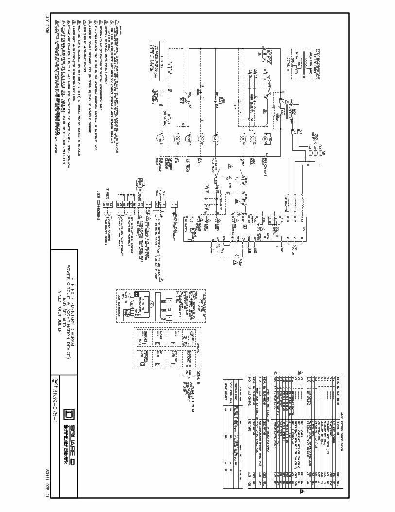
4 Approval Elementary Wiring Diagrams 8839-071-1
through8839-079-1
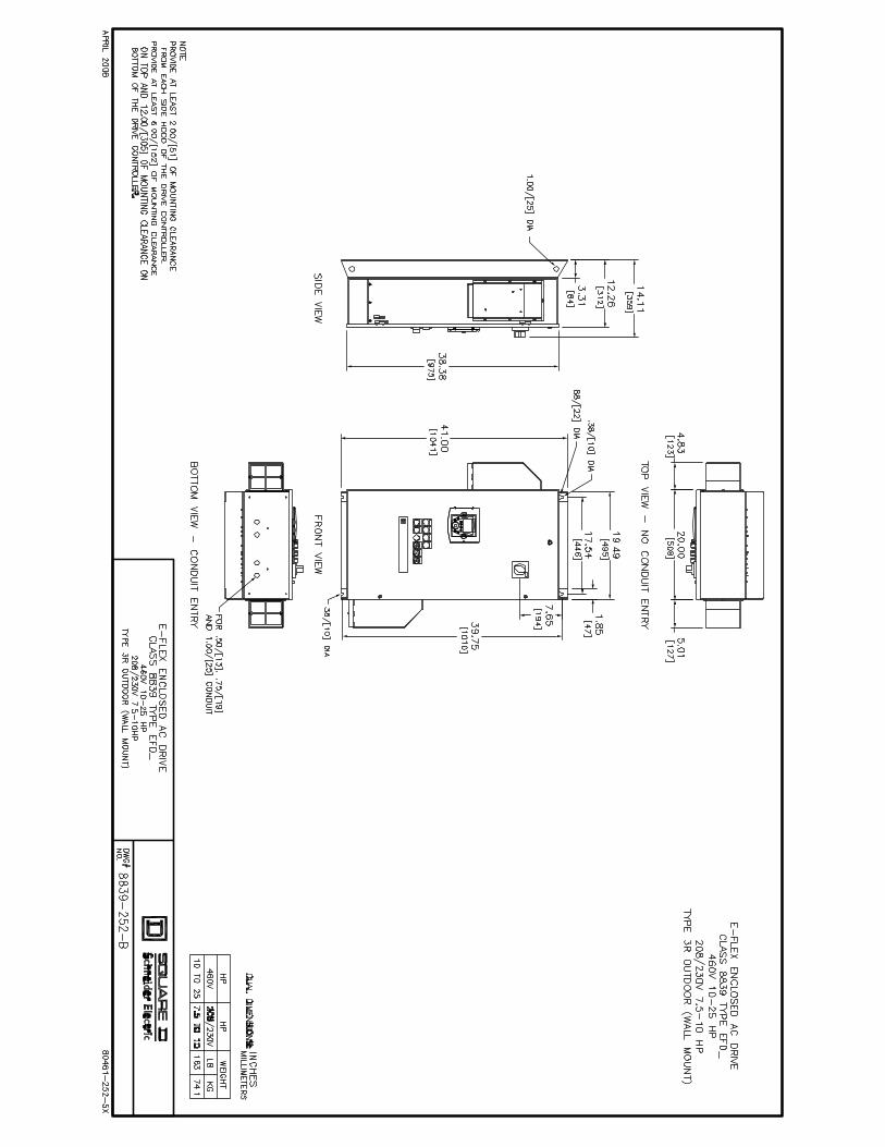
5 Enclosure Outline Diagrams 8839-250-A
through8839-253-B
6 E-Flex™ Enclosed Drive Controllers Brochure 8800BR0501
7 Specifications for Centrifugal Pump and Fan Applications 16420-4.2
8 E-Flex™ Adjustable Speed Drive Controllers Instruction Bulletin
30072-451-51
TA
BLE
OF
CO
NTE
NTS
— S
UB
MIT
TAL
RES
OU
RC
E B
IND
ER F
OR
CLA
SS 8
839
E-FL
EXTM
AC
DR
IVES

Bulletin No. 8839SM0701 February 2007

Bulletin No. 8839SM0702 February 2007
Preparing Submittals for Class 8839 E-Flex™ AC Drives
The submittal package should consist of a Drawing Transmittal Cover Sheet and drawing documentation as listed below. The documentation supplied to the customer is based on the horsepower, voltage, power circuit, and option requirements. 1. Drawing Transmittal Cover, 8839SM0601 (see Tab 2). 2. E-Flex™ Product Data Bulletin, Specification Data, 8839DB0701 (see Tab 3). 3. Approval Elementary Wiring Diagrams, 8839-071-1 through 8839-079-1 (see Tab 4, Quote
to Cash, or www.SquareD.com). Elementary Wiring Diagram No.
Power Circuit Control Circuit
8839-071-1 Y: Circuit Breaker with Bypass HAND-OFF-AUTO, Start-Stop, and Speed Potentiometer
8839-072-1 Y: Circuit Breaker with Bypass HAND-OFF-AUTO and Speed Potentiometer
8839-073-1 W: Circuit Breaker without Bypass HAND-OFF-AUTO, Start-Stop, and Speed Potentiometer
8839-074-1 W: Circuit Breaker without Bypass Start-Stop and Speed Potentiometer
8839-075-1 W: Circuit Breaker without Bypass HAND-OFF-AUTO and Speed Potentiometer
8839-078-1 Y: Circuit Breaker with Bypass HAND-OFF-COMM, Start-Stop and Speed Potentiometer
8839-079-1 W: Circuit Breaker without Bypass HAND-OFF-COMM, Start-Stop and Speed Potentiometer
4. Enclosure Outline Diagrams, 8839-250-A through 8839-252-B (see Tab 5, Quote to Cash, or www.SquareD.com).
Outline and Elevation Drawing No. Horsepower Rating and Voltage Class Type 1 and Type 12 Enclosures
Type 3R Enclosure 460 V 208/230 V
8839-250-A 8839-252-A 1–7.5 hp VT 1–5 hp VT
8839-250-B 8839-252-B 10–25 hp VT 7.5–10 hp VT
8839-251-A 8839-253-A 30–50 hp VT 15–25 hp VT
8839-251-B 8839-253-B 60–100 hp VT 30–50 hp VT
In some cases, a sales brochure, specifications, or a copy of the instruction bulletin may be required. 5. E-Flex™ Enclosed Drive Controllers Brochure, 8800BR0501 (see Tab 6). 6. Specifications for Centrifugal Pump and Fan Applications, Specification Number 16420-4.2
(see Tab 7). 7. E-Flex™ Adjustable Speed Drive Controllers Instruction Bulletin, 30072-451-51A
(see Tab 8).
Note: The Class 8839 E-Flex™ AC Drive is pre-engineered and marketed specifically for HVAC pump and fan applications. This binder contains all of the documentation for this product. All documents are available electronically. To download the files or order additional binders, use the Online Literature Fulfillment system, accessible from the Business Tools pull-down on the home page of the Square D Intranet.
Page 1 of 2

Bulletin No. 8839SM0702 February 2007
Page 2 of 2

Bulletin No. 8839SM0601 December 2006
DRAWING TRANSMITTAL
Submittal Date: Set(s) of drawings with copies for: Approval Record
Distributor: Distributor Order #: Account #: Quote to Cash Order #: Type of Equipment: Job Name: Location: Architect: Consulting Engineer: Field Representative: Field Office: Factory Contact: Technical Assistance: 888 SQUARED (888 778-2733)
NOTICE:
To avoid price escalation, approved drawings must be returned to Schneider Electric and the order must be released for normal shipment within sixty (60) days or by _________.
This order is on "HOLD STATUS" and will not be scheduled for production until approved drawings are returned to Schneider Electric. Please call the factory for a shipping schedule upon release of approved drawings.
If "APPROVED AS NOTED" drawings require additional equipment that was not included in the original quotation, the cost of any additional equipment will be reflected in the total invoice price.

Bulletin No. 8839SM0601 December 2006
Page 2 of 6
MOTOR CONTROL SCHEDULE Distributor:
Account #:
Purchase Order #:
Quote to Cash Order #:
Job Name:
Volts Amperes Diagrams Item # Qty Designation and Description Class, Type and Mod
hp
Line Control Input Output Wiring/Dimension
Notes:

Bulletin No. 8839SM0601 December 2006
Page 3 of 6
MOD DESCRIPTIONS
Mod # Modification Description

Bulletin No. 8839SM0601 (sample) December 2006
DRAWING TRANSMITTAL
Submittal Date: 8/16/2006
3 Set(s) of drawings with 1 copies for: X Approval Record
Distributor: ABC Distributor Order #: 123 Account #: 654321 Quote to Cash Order #: QC0001 Type of Equipment: AC DRIVES Job Name: STATE TOWERS Location: SOMEWHERE, USA Architect: Consulting Engineer: CDM Field Representative: JOE SMITH Field Office: SOMEWHERE, USA 555-123-4567 Factory Contact: Technical Assistance: 888 SQUARED (888 778-2733)
NOTICE:
To avoid price escalation, approved drawings must be returned to Schneider Electric and the order must be released for normal shipment within sixty (60) days or by 10/15/2006.
This order is on "HOLD STATUS" and will not be scheduled for production until approved drawings are returned to Schneider Electric. Please call the factory for a shipping schedule upon release of approved drawings.
If "APPROVED AS NOTED" drawings require additional equipment that was not included in the original quotation, the cost of any additional equipment will be reflected in the total invoice price.
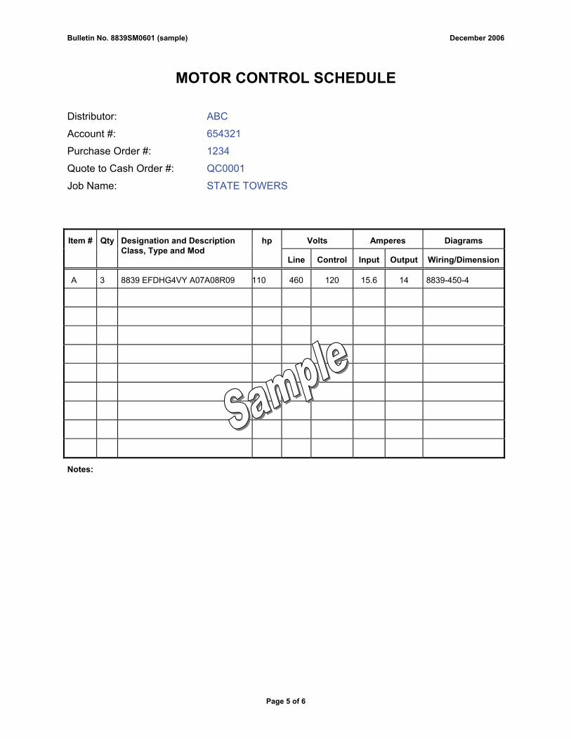
Bulletin No. 8839SM0601 (sample) December 2006
Page 5 of 6
MOTOR CONTROL SCHEDULE Distributor: ABC
Account #: 654321
Purchase Order #: 1234
Quote to Cash Order #: QC0001
Job Name: STATE TOWERS
Volts Amperes Diagrams Item # Qty Designation and Description Class, Type and Mod
hp
Line Control Input Output Wiring/Dimension
A 3 8839 EFDHG4VY A07A08R09 110 460 120 15.6 14 8839-450-4
Notes:

Bulletin No. 8839SM0601 (sample) December 2006
Page 6 of 6
MOD DESCRIPTIONS
Mod # Modification Description
A07 HAND-OFF-AUTO Selector Switch and Speed Pot
A08 Light Cluster – red Power On, green AFC Run, yellow AFC Fault, yellow Auto
R09 BACnet Communications Card

1
Data Bulletin8839DB0701
02/2007Raleigh, NC, USA
E-Flex™ Enclosed Drive ControllerSpecification DataClass 8839Retain for future use.
Features
The E-Flex™ Enclosed Drive Controller is available in:
• 1 to 50 hp at 208 Vac and 230 Vac
• 1 to 100 hp at 460 Vac
Built to provide an efficient and economical application solution, the E-Flex™ Enclosed Drive Controller offers:
❏ Performance under pressure
• UL 508C Listed to exceed minimum UL short-circuit requirements
• 100,000 AIC short circuit protection without current limiting fuses
• Advanced technology platform increases reliability and uptime; reducing the number of components needed on hand.
• Industrial-rated control operators and pilot devices
❏ Easy to Control
• Large backlit LCD graphic screen with customizable display
• Clear text in six languages
• Navigation wheel for easy scrolling through menus
• Pre-programmed for HVAC variable torque operation
• Light indicators for Power, Fault, Run, and Bypass
• Test-Normal selector switch permits testing of the drive controller
❏ Fully Protected
• Circuit breaker disconnect provides short circuit protection
• 3% line reactor provides transient protection from surge and overvoltage conditions, and minimizes line harmonics
• Enclosure designed to reduce radio frequency interference
• Meets International Building Code and ASCE1 standards for seismic specifications
• Thermal management system for operation in extreme temperatures 14 °F to 122 °F (-10 °C to 50 °C) for Type 3R enclosures
❏ Expandable Capabilities
• LonWorks®, BACnet, Modbus® Unitelway, Ethernet TCP/IP, Apogee® P1, Profibus, and Metasys® N2 communications capability
• HVAC controls provide end damper, smoke purge relays, and fire/freeze stat for full speed fire safety override
Applications
Well suited for commercial buildings, hospitals, airports, schools, and water/wastewater facilities HVAC pump and fan applications, the Square D brand E-Flex™ enclosed drive controller provides an efficient and economical AC drive solution.
Designed to withstand harsh environments in demanding commercial buildings, the E-Flex™ Enclosed Drive Controller meets building code seismic specifications for ground level and roof mounted applications.
AC drives help increase the energy efficiency of HVAC equipment by reducing motor speeds, thereby reducing electricity usage in:
• Air handling units
• Supply and return fans
• Ventilation fans
• Cooling tower pumps and fans
• Hot water pumps
• Chilled water pumps
1American Society of Civil Engineers
E-Flex™ Enclosed Drive Controller 8839DB0701Specifications 02/2007
© 2007 Schneider Electric All Rights Reserved2
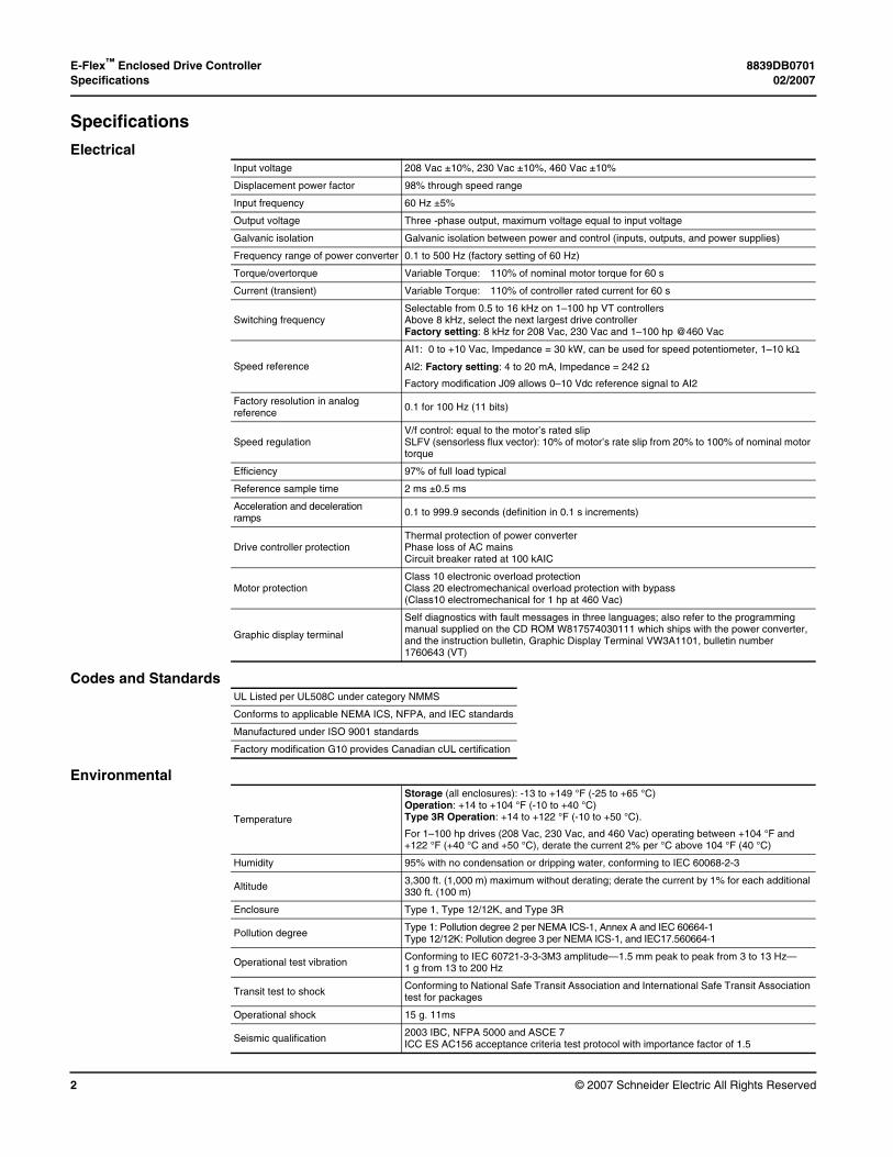
Specifications
Electrical
Codes and Standards
Environmental
Input voltage 208 Vac ±10%, 230 Vac ±10%, 460 Vac ±10%
Displacement power factor 98% through speed range
Input frequency 60 Hz ±5%
Output voltage Three -phase output, maximum voltage equal to input voltage
Galvanic isolation Galvanic isolation between power and control (inputs, outputs, and power supplies)
Frequency range of power converter 0.1 to 500 Hz (factory setting of 60 Hz)
Torque/overtorque Variable Torque: 110% of nominal motor torque for 60 s
Current (transient) Variable Torque: 110% of controller rated current for 60 s
Switching frequencySelectable from 0.5 to 16 kHz on 1–100 hp VT controllers Above 8 kHz, select the next largest drive controllerFactory setting: 8 kHz for 208 Vac, 230 Vac and 1–100 hp @460 Vac
Speed reference
AI1: 0 to +10 Vac, Impedance = 30 kW, can be used for speed potentiometer, 1–10 kΩ.
AI2: Factory setting: 4 to 20 mA, Impedance = 242 Ω
Factory modification J09 allows 0–10 Vdc reference signal to AI2
Factory resolution in analog reference 0.1 for 100 Hz (11 bits)
Speed regulationV/f control: equal to the motor’s rated slip SLFV (sensorless flux vector): 10% of motor’s rate slip from 20% to 100% of nominal motor torque
Efficiency 97% of full load typical
Reference sample time 2 ms ±0.5 ms
Acceleration and decelerationramps 0.1 to 999.9 seconds (definition in 0.1 s increments)
Drive controller protectionThermal protection of power converterPhase loss of AC mainsCircuit breaker rated at 100 kAIC
Motor protectionClass 10 electronic overload protectionClass 20 electromechanical overload protection with bypass (Class10 electromechanical for 1 hp at 460 Vac)
Graphic display terminal
Self diagnostics with fault messages in three languages; also refer to the programming manual supplied on the CD ROM W817574030111 which ships with the power converter, and the instruction bulletin, Graphic Display Terminal VW3A1101, bulletin number 1760643 (VT)
UL Listed per UL508C under category NMMS
Conforms to applicable NEMA ICS, NFPA, and IEC standards
Manufactured under ISO 9001 standards
Factory modification G10 provides Canadian cUL certification
Temperature
Storage (all enclosures): -13 to +149 °F (-25 to +65 °C)Operation: +14 to +104 °F (-10 to +40 °C) Type 3R Operation: +14 to +122 °F (-10 to +50 °C).
For 1–100 hp drives (208 Vac, 230 Vac, and 460 Vac) operating between +104 °F and +122 °F (+40 °C and +50 °C), derate the current 2% per °C above 104 °F (40 °C)
Humidity 95% with no condensation or dripping water, conforming to IEC 60068-2-3
Altitude 3,300 ft. (1,000 m) maximum without derating; derate the current by 1% for each additional 330 ft. (100 m)
Enclosure Type 1, Type 12/12K, and Type 3R
Pollution degree Type 1: Pollution degree 2 per NEMA ICS-1, Annex A and IEC 60664-1Type 12/12K: Pollution degree 3 per NEMA ICS-1, and IEC17.560664-1
Operational test vibration Conforming to IEC 60721-3-3-3M3 amplitude—1.5 mm peak to peak from 3 to 13 Hz—1 g from 13 to 200 Hz
Transit test to shock Conforming to National Safe Transit Association and International Safe Transit Association test for packages
Operational shock 15 g. 11ms
Seismic qualification 2003 IBC, NFPA 5000 and ASCE 7ICC ES AC156 acceptance criteria test protocol with importance factor of 1.5

8839DB0701 E-Flex™ Enclosed Drive Controller02/2007 Dimensions and Weights
© 2007 Schneider Electric All Rights Reserved 3
Dimensions and Weights Figure 1: Type 1 or Type 12/12K EnclosureDimensions (mm and inches) and Weights (kg and lbs)
NOTE: Provide at least 3 inches (76.2 mm) of mounting clearance on each side of the drive controller and at least 6 inches (152.4 mm) of mounting clearance at the top and bottom of the drive controller.
Height
1.85 (46.89 mm)
Width
6.11 (155.09 mm
∅ 0.38 (9.53 MM)
∅ 0.88 (22.35 mm)
∅ 0.37 (9.40 mm)
Depth
3.01 (76.45 mm)
∅ 1.00 (25.40 mm)
Lifting Hole
Vents in Type 1 Only
hp Height Width Depth Weight
208/230 Vac 460 Vac mm in. mm in. mm in. kg lbs
1–5 1–7.5 889 35 374.9 14.76 353.91 13.93 37.7 83
7.5–10 1–25 1041.4 41 521.21 20.52 353.91 13.93 57.2 126
15–25 30–50 1244.6 49 524.51 20.65 427.49 16.83 80.5 177
30–50 60–100 1600.2 63 651.51 25.65 427.49 16.83 95.9 211

E-Flex™ Enclosed Drive Controller 8839DB0701Dimensions and Weights 02/2007
© 2007 Schneider Electric All Rights Reserved4
Figure 2: Type 3R EnclosureDimensions (mm and inches) and Weights (kg and lbs)
NOTE: Provide at least 2 inches (50.8 mm) of mounting clearance from each side hood, at least 6 inches (152.4 mm) of mounting clearance at the top and at least 12 inches (304.8mm) of mounting clearance at the bottom of the drive controller.
Top View
Top hood on 30 - 100 hp 460V,15 - 50 hp 208/230V only
4.81 (122.18 mm)
4.88 (123.98 mm)
4.87 (123.75 mm)
Height
Depth
Width
hp Height Width Depth Weight
208/230 Vac 460 Vac mm in. mm in. mm in. kg lbs
1–5 1–7.5 889 35 620.52 24.43 347.73 13.69 52.3 115
7.5–10 10–25 1041.4 41 766.83 30.19 347.73 13.69 74.1 163
15–25 30–50 1326.39 52.22 770.13 30.32 415.04 16.34 96.8 213
30–50 60–100 1681.99 66.22 897.13 35.32 415.04 16.34 112.3 247

8839DB0701 E-Flex™ Enclosed Drive Controller02/2007 Power Circuit Configuration
© 2007 Schneider Electric All Rights Reserved 5
Power Circuit Configuration
NON-BYPASS: Power Circuit W The Power Circuit W assembly includes:
• 120 Vac fused control transformer
• Circuit breaker disconnect with means for locking in the open position
• Hand-Off-Auto switch provided as the standard control interface unless other options are selected
BYPASS: Power Circuit Y The Power Circuit Y assembly includes:
• IEC-rated isolation and bypass contactors with mechanical and electrical interlocking and a Class 20 overload relay
• 120 Vac fused control transformer and circuit breaker disconnect with lockout/tag out capability
• AFC-Off-Bypass switch and Hand-Off-Auto switch provided as standard control interface unless other options are selected
• Test-Normal selector switch provides drive controller testing capability without running the motor, and allows drive controller testing if bypass mode is selected. The isolation contactor is sequenced open to provide drive isolation during the test mode.
M
CB
AFCControl Circuit
120 Vac
120 Vac
M
CB
IC BC
OL
AFCControl Circuit
MechanicalInterlock
OptionalLine Contactor

E-Flex™ Enclosed Drive Controller 8839DB0701Power Circuit Configuration 02/2007
© 2007 Schneider Electric All Rights Reserved6
Catalog Identification Numbers The controller catalog number, located on the nameplate on the inside of the door, is coded to describe the configuration and options present. Use the following grid to translate the catalog number into a description of the drive controller.
Class Type Modification ➆ Control Option
Control Light Misc. Code AFC Controls
8839 EFD • • • V • • • • A071 Hand/Off/Auto, Speed Potentiometer
➀ ➁ ➂ ➃ ➄ ➅ ➆ ➇ ➈ B071 Hand/Off/Auto, Start/Stop, Speed Potentiometer
➀ Product C072 Start/Stop, Speed Potentiometer
Code Drive D07 Hand-Off-Comm, Speed Potentiometer
EFD E-Flex Controller E07 Hand-Off-Comm, Start/Stop, Speed Potentiometer
➁ Horsepower Code N07 None
Code hp Rating Code hp Rating ➇ Light Option
C 1 L 25 Code Light Cluster
D 2 M 30
A083, 4
Red Power On
E 3 N 40 Green AFC Run
F 5 P 50 Yellow AFC Fault
G 7.5 Q 60 (460 Vac only) Yellow Auto
H 10 R 75 (460 Vac only)
B083, 5
Red Power On
J 15 S 100 (460 Vac only) Green AFC Run
K 20 Yellow AFC Fault
➂ Enclosure Type Yellow Bypass
Code Environmental Rating
C083, 6Red Power On
A7 Type 12K Green AFC Run
G Type 1 Yellow AFC Fault
H Type 3R (outdoor) ➈ Miscellaneous Options
➃ Voltage Rating Code Feature
Code Voltage A09 Line Reactor 5%
28 208 B099, 10 Line Contactor
38 230 C0911 3–15 PSI Transducer
4 460 D0912 Omit Keypad
➄ Application Type E0913 Smoke Purge (Fireman’s Override)
Code Applied Rating F0914, 19 Profibus
V Variable Torque H0915 I/O Extension Analog Card, 0–20 mA output, 4 logic inputs, 2 logic outputs, 2 analog inputs, 1 differential analog output
➅ Device Type J0916 0–10 Vdc Auto Speed Reference
Code Power Circuit K0917 cUL Listing Certification
W18 Without Bypass L0914, 19, 20 LonWorks Card
Y21 Bypass M0914, 19 ModBus/Unitelway Card
O0914, 19 Apogee P1 Card
P0914, 19 Metasys N2 Card
Q0914, 19 Ethernet TCP/IP Card
R0914, 19 BACnet Card
S0922 End Damper Control
U09 Seismic Qualification

8839DB0701 E-Flex™ Enclosed Drive Controller02/2007 Modifications
© 2007 Schneider Electric All Rights Reserved 7
1 Hand-Off-Auto switch must be placed in the Off position for AFC fault reset.2 Control option C07 (Start/Stop, Speed Potentiometer) is not compatible with Power Circuit Y (Bypass) or light options A08 or B08.3 Light Options A08, B08 and C08 cannot be selected together. Select only one option.4 Light Option A08 is compatible with Control Options A07, B07, D07 and E07.5 Light option B08 is not compatible with Power Circuit W (Without Bypass).6 Light option C08 is not compatible with A07 (Hand/Off/Auto, Speed Potentiometer), B07 (Hand/Off/Auto, Start/Stop, Speed Potentiometer),
D07 (Hand-Off-Comm, Speed Potentiometer), or E07 (Hand-Off-Comm, Start-Stop, Speed Potentiometer).7 Type 12 Enclosure with knock-outs.8 208 Vac and 230 Vac ratings are not available in 60 hp, 75 hp, and 100 hp horsepower ratings.9 Line contactor B09 is not compatible with Power Circuit W (Without Bypass).10 Miscellaneous Option B09 (Line Contactor) is not compatible with H03 (Type 3R Enclosure).11 Miscellaneous Option C09, 3–15 PSI Transducer, is not compatible with Control option C07, D07 or E07, J09 0–10 Vdc Auto Speed Reference Option, H09 I/O
Extension Card, F09, L09, M09, O09, P09, Q09 and R09 Serial Communication Cards.12 Omit the keypad option D09 from enclosure door, the user must buy a separate device to program the controller inside.13 Smoke purge (Fireman's Override) Miscellaneous Option E09 permits the motor to run at full speed.14 Control Option D07 or E07 must be selected.15 I/O Extension Analog Card H09 is not compatible with C09 3–15 PSI Transducer or serial communication F09, L09, M09, O09, P09, Q09 or R09.16 Miscellaneous Option J09, 0–10 Vac Auto Speed Reference, is not compatible with Control Options C07, D07 or E07 or Miscellaneous Option C09, 3–15 PSI
Transducer.17 K09 requires Hypot of Controller.18 W06 (Without Bypass Option) includes Form C AFC Run Contact, Form C AFC Fault Contact and Fire/Freeze Stat interlock.19 Serial communication F09, L09, M09, O09, P09, Q09 and R09 cannot be selected together. Select only one. Serial communication and Miscellaneous Option H09
are not compatible.20 Communication Option L09 with Control Option D07 or E07 is for monitoring and control.21 When Y06 Bypass is selected, AFC/Off/Bypass switch and Test/Normal switch are supplied.22 Miscellaneous Option S09 (End Damper Control) is not compatible with Control Options D07 (Hand-Off-Comm, Speed Potentiometer) or E07 (Hand-Off-Comm,
Start-Stop, Speed Potentiometer).

E-Flex™ Enclosed Drive Controller 8839DB0701Modifications 02/2007
© 2007 Schneider Electric All Rights Reserved8
Modifications
Enclosure Modifications Type 12K Enclosure (if used)
Replaces the Type 1 enclosure with a Type 12 enclosure with bottom-only conduit knockouts, to provide an additional degree of protection in dusty and dripping-liquid environments.
Type 3R Enclosure (if used)
Replaces the Type 1 enclosure with a Type 3R enclosure with bottom-only conduit knockouts, to provide an additional degree of protection in outdoor environments. The controller's ambient operating temperature is -10 to 50 °C (14 to 122 °F).
Modification Options MOD A07 Hand-Off-Auto and Speed Potentiometer (factory supplied)
Provides a two-wire control strategy and allows auto restart capability. Moving the Hand-Off-Auto switch to the Off position resets a drive fault condition.
MOD B07 Hand-Off-Auto, Start/Stop, and Speed Potentiometer (if used)
Provides a three-wire hand mode control strategy, momentary Start and Stop pushbuttons, and a manual speed potentiometer to the factory-supplied Hand-Off-Auto selector switch. In the Hand mode only, this option will not allow auto restart capability. Moving the Hand-Off-Auto switch to the Off position resets a drive fault condition.
MOD C07 Start/Stop and Speed Potentiometer Only (if used)
Replaces the factory-supplied Hand-Off-Auto selector switch with momentary Start and Stop pushbuttons. Speed control is accomplished via the door-mounted LCD display and navigation wheel. Automatic (remote) mode selection is not provided.
MOD N07 Delete Hand-Off-Auto Switch and Manual Speed Potentiometer (if used)
Removes the factory-supplied Hand-Off-Auto switch. Under certain conditions, the user may prefer to control the power converter by means of a remote or external source only. The user provides the control sequence logic. Refer to instruction bulletin 30072-451-51A for details on the recommended sequence of operation.
MOD A08 Pilot Light Cluster (if used)
Provides visual indication of protective functions and circuit status. The pilot devices are rated 120 Vac. Included within this configuration are:
• Power On (Red): Illuminates whenever mains power is applied to the controller.
• AFC Run (Green): Illuminates whenever drive output relay R2 (programmed for running state) is high, to annunciate a drive run condition.
• Auto Mode (Yellow): Illuminates whenever the Hand-Off-Auto switch is in the Auto position, controlled by a contact block on the switch.
• AFC Fault (Yellow): Illuminates (via relay ADFR) whenever drive output relay R1 (programmed for fault state) is low, to annunciate a fault condition. This light is normally off until a drive protective circuit has caused a shutdown.

8839DB0701 E-Flex™ Enclosed Drive Controller02/2007 Modifications
© 2007 Schneider Electric All Rights Reserved 9
MOD B08 Pilot Light Cluster (if used)
Provides visual indication of protective functions and circuit status. Only available on power circuit Y. The pilot light devices are rated 120 Vac. Included within this configuration are:
• Power On (Red): Illuminates whenever mains power is applied to the controller.
• AFC Run (Green): Illuminates whenever drive output relay R2 (programmed for running state) is high, to annunciate a drive run condition.
• Bypass Run (Yellow): Illuminates whenever the bypass contactor coil is energized.
• AFC Fault (Yellow): Illuminates (via relay ADFR) whenever drive output relay R1 (programmed for fault state) is low, to annunciate a fault condition. This light is normally off until a drive protective circuit causes a shutdown.
MOD C08 Pilot Light Cluster (if used)
Provides visual indication of protective functions and circuit status. The pilot devices are rated 120 Vac. Included within this configuration are:
• Power On (Red): Illuminates whenever mains power is applied to the controller.
• AFC Run (Green): Illuminates whenever drive output relay R2 (programmed for running state) is high, to annunciate a drive run condition.
• AFC Fault (Yellow): Illuminates (via relay ADFR) whenever drive output relay R1 (programmed for fault state) is low, to annunciate a fault condition. This light is normally off until a drive protective circuit causes a shutdown.
MOD A09 Line Reactor (if used)
Provides a 5% AC line reactor factory-wired between the circuit breaker and the power converter terminals L1, L2, and L3. 3% line reactors are included in the drive controller as standard on all horsepower ratings.
MOD B09 Line Isolation Contactor (if used)
Provides a line isolation contactor factory-wired between the circuit breaker and the power converter terminals L1, L2, and L3. This Mod is only available with bypass configurations (power circuit Y), as well as Type 1 and Type 12K enclosures.
MOD C09 3–15 PSI Module (if used)
Provides a pneumatic transducer to allow the controller to follow a user-supplied 3–15 PSI speed reference signal.
MOD D09 Omit Keypad (if used)
Omits the keypad interface from the enclosure door. The end user must buy a separate device to program the controller.
MOD E09 Smoke Purge Option (Fireman’s Override) (if used)
A smoke purge relay (SPR) permits the motor to operate at full speed. When a bypass is supplied, the controller will operate in the bypass mode. This circuit requires a user-supplied 120 Vac signal to energize the SPR relay to run the motor at full speed.
MOD F09 Profibus Serial Communication (if used)
Provides a factory installed plug-in Profibus card, VW3A3307.

E-Flex™ Enclosed Drive Controller 8839DB0701Modifications 02/2007
© 2007 Schneider Electric All Rights Reserved10
MOD H09 I/O Extension 0-20 mA Analog Output (if used)
Provides an analog I/O extension card, VW3A3202, factory-installed on the drive controller to provide a 4–20 mA selectable analog output for customer use. The analog output is factory programmed for motor frequency. Reassignable X-Y range with keypad display. Also includes logic inputs, logic outputs, analog inputs, analog outputs, configurable relay outputs, PTC probe input, and frequency control input.
MOD J09 Automatic Speed Reference 0–10 Vdc Input (if used)
Provides a factory programming change to allow AI2 to be a 0–10 Vac analog input rather than 4– 20 mA input for the automatic mode of operation.
MOD K09 cUL Listing (if used)
Provides Canadian cUL certification when required by local code requirements.
MOD L09 LonWorks® Serial Communication (if used)
Provides factory-installed LonWorks communications card, VW3A3312.
MOD M09 ModBus® Serial Communication (if used)
Provides factory-installed plug-in ModBus card, VW3A3303.
MOD O09 Apogee® P1 Serial Communication (if used)
Provides factory-installed Apogee P1 communications card, VW3A3314.
MOD P09 Metasys® N2 Serial Communication (if used)
Provides factory-installed Metasys N2 communications card, VW3A3313.
MOD Q09 Ethernet TCP/IP Serial Communications (if used)
Provides factory installed Ethernet TCP/IP communications card, VW3A3310.
MOD R09 BACnet Serial Communication (if used)
Provides factory installed BACnet communications card, VW3A3315.
MOD S09 End Damper Control (if used)
Provides a circuit to delay drive operation until the damper is fully open.
MOD U09 Seismic Qualified
Provides a certification label and hardware qualified to seismic rating ICC ES AC156 acceptance criteria test protocol with an importance factor of 1.5.


E-Flex™ Enclosed Drive Controller 8839DB0701Data Bulletin 02/2007
Electrical equipment should be installed, operated, serviced, and maintained only by qualified personnel. No responsibility is assumed by Schneider Electric for any consequences arising out of the use of this material.
© 2007 Schneider Electric All Rights Reserved
Schneider Electric USA8001 Knightdale Blvd.Knightdale, NC 27525-9023 USA1-888-SquareD (1-888-778-2733)www.us.SquareD.com


E-Flex™ Enclosed Drive ControllersAdjustable speed solutions forHVAC and pump applications

�
Seismic Qualification for Ground and Roof Level ApplicationsSquare D E-Flex enclosed drive controllers are designed to withstand harsh environments and meet the 2003 IBC and ASCE 7 standards for seismic qualification in accordance with ICC ES AC156 testing protocol.
E-Flex enclosed drive controllers were subjected to actual shaker table tests for seismic ratings, not just theoretical anchorage and bolt-hole calculations. When mounted in accordance with published guidelines, the E-Flex drive enclosure is designed and constructed to withstand violent transfer of both vertical and transverse axial vibration loads. This means that these controllers have structural integrity and can be specified with the assurance that it can continue to keep a facility running smoothly after a seismic event.
Enclosure StylesSquare D E-Flex enclosed drive controllers can meet both indoor and outdoor application requirements with Type 1, Type 12/12K and Type 3R enclosures.
n Type 1 enclosures are designed specifically for indoor, non-dusty environments
n Type 12/12K enclosures are designed for protection from dust and dripping liquid
n Type 3R enclosures permit installation on rooftops or other outdoor locations to free up space in mechanical equipment rooms. Plus, Type 3R enclosures allow operations in temperature ranges from +14˚ to +122˚F (-10˚C to +50˚C)
Industrial-grade reliability designed for HVAC
Square D®E-Flex™ AC drives provide the optimum combination of efficiency and economy for HVAC, pump and fan applications in both commercial and industrial environments. They are the ideal choice in adjustable speed drive solutions for applications such as:
n Air Handling Units
n Supply and Return Fans
n Exhaust Fans
n Chilled Water Pumps
n Hot Water Pumps
n Cooling Tower Fans and Pumps

�
Motor Speed
PercentFlow, HP, Pressure
Percent Speed
100
8090
70605040302010
10 20 30 40 50 60 70 80 90 1000
A
B
C
A = Flow as a function of motor speed
B = Pressure as a function of motor speed
C = Horsepower as a function of motor speed
A
B
C
An Example of an Energy Saving Calculation*A fan with a 20 horsepower motor supplies air 10 hours a day for 260 days a year and the energy cost is of $0.10 cents per kilowatt-hour.
Cost of running full speed:
20 hp x 0.746 kW/hp x 2600 hours x $0.10/kWhr = $3879.20
Assuming the fan does not need to run at full speed all of the time, let’s use an example of:
n Running full speed (100%) for 25% of the time n 80% speed for 50% of the timen 60% speed for the remaining 25% of the time
Cost of running with an AC drive controlling the motor:
20 hp x (1)3 x 0.746 kW/hp x 650 hours x $0.10/kWhr = $969.8020 hp x (0.8)3 x 0.746 kW/hp x 1300 hours x $0.10/kWhr = $993.0820 hp x (0.6)3 x 0.746 kW/hp x 650 hours x $0.10/kWhr = $209.48
Total = $2172.36
Annual savings: $�879.�0 - $�17�.�6 = $1706.84
n In many instances, the payback period for using an adjustable frequency drive in place of other flow control methods is less than 18 months.
Actual results may vary for closed loop pumping and variable air volume systems.
Energy EfficiencySquare D E-Flex enclosed drive controllers can increase system energy efficiency by providing a means to reduce the motor speed of HVAC equipment based on the needs of the building environment (Lower motor speed = Lower energy costs).
Energy Savings can be realized because of the Affinity laws of physics:
n Flow = f (motor speed)
n Pressure = f (motor speed)2
n Horsepower = f (motor speed)3
A motor running at 50% of full speed capacity has a motor torque of 25% of full speed and the electricity required to operate the motor at 50% of full speed is at 12.5%. Thus, reducing motor speed can significantly reduce the electrical energy consumption.

4
Industrial rated control operators and pilot devices accommodate the most demanding environments
Red Power Light
Yellow AFC Fault Light
Green AFC Run Light
Yellow Bypass Light
Graphic screen with custom-izable display in plain text
Navigation wheel for easy surfing through the menus
Manual speed potentiometer
Test normal selector switch allows drive testing
Pre-punched top and bottom conduit entry knock-outs simplifies electrical installation and prevents metal filings from getting inside the enclosure (Type 3R have bottom conduit entry only)
The Square D® E-Flex™ family of enclosed drive controllers are well suited for commercial building, hospital and school HVAC applications requiring a disconnect and bypass. These controllers offer a compact metal enclosure design to reduce Radio Frequency Interference (RFI). In addition, HVAC specific control interface is pre-programmed for HVAC variable torque operation to permit easy set-up and installation. HVAC controls provide end damper control, smoke purge relays and fire freeze stats for full speed fire safety override and lock out terminations.
Disconnect means with lock out/tag out provisions
Hand Off auto selector switch
Start push button
Stop push button
AFC Off bypass switch
Side Air Vents (Type 1 only)

�
A 3% line reactor is included as standard and provides transient protection from surge, overvoltage and mini-mizes line harmonic currents.5% line reactor is optional.
Type 2B wiring simplifies wiring identification and termination to industrial rated terminals
Motor isolation and bypass contactors for emergency full speed operation
3-15 PSI pressure transducer input for retrofit applications
Circuit breaker disconnect (L1, L2, L3) provides short circuit protection without current limiting fuses
Control transformer
Altivar 61 drive power convertor with 6 pulse bridge rectifier input and IGBT invertor with pulse Width modulated output
Customer interface terminal blocks
Integrated Modbus and CANopen port
Serial communication card options include: LonWorks®, BACnet®, Ethernet, Profibus, Modbus® Unitelway, Apogee P1 and Metasys® N2
Front removable heat sink fan assembly eliminates rear access requirements, improving maintenance and minimizing downtime
Motor terminal connection bypass Circuit (T1, T2, T3)
UL 508C listed and coordinated with NEMA ICS 7.1 standards to exceed minimum UL short circuit requirements (this structural integrity will provide enhanced personnel safety under short circuit conditions for the drive and by-pass operation)
Fully-rated, AC3 duty-rated motor isolation and bypass contactors with mechanical and electrical interlocks prevent accidental voltage back feed. The adjustable carrier frequency is optimized at 8 kHz to reduce motor noise levels and is programmable from 0.5 kHz to 16 kHz. Advanced ASIC technology platform increases reliability and uptime and lowers the component count. The inherent motor soft start with the drive reduces mechanical stress and reduces routine maintenance.

6
Selection GuideThe controller catalog number, located on the inside of the door, is coded to describe the configuration and options present. Use the following grid to translate the catalog number into a description of the controller.
Class Type Modifications Control Light Misc.8839 EFD . . . V .
1 2 3 4 5 6
. . .7 8 9
1 Product
Code Drive TypeEFD E-Flex Controller
� Horsepower CodeCode HP RatingC 1 hpD 2 hpE 3 hpF 5 hpG 7.5 hpH 10 hpJ 15 hpK 20 hp
Code HP RatingL 25 hpM 30 hpN 40 hpP 50 hpQ 60 (460V only)R 75 (460V only)S 100 (460V only)
� Enclosure TypeCode Environmental RatingA Type 12KG Type 1H [5] Type 3R
4 Voltage RatingCode Voltage2 208 V3 230 V4 460 V
� Application TypeCode Applied RatingV Variable Torque
6 Device TypeCode Power CircuitW [5] Without BypassY [8] Bypass
7 Control OptionCode AFC ControlsA07 [7] Hand-Off-Auto, Speed PotentiometerB07 [7] Hand-Off-Auto, Start-Stop, Speed PotentiometerC07 [1] Start-Stop, Speed PotentiometerD07 Hand-Off-Comm, Speed PotentiometerE07 Hand-Off-Comm, Start-Stop, Speed PotentiometerN07 None
8 Light OptionCode Light ClusterA08 [2] Red Power On
Green AFC RunYellow AFC FaultYellow Auto
B08 [2], [3] Red Power OnGreen AFC RunYellow AFC FaultYellow Bypass
C08 [2], [4] Red Power OnGreen AFC RunYellow AFC Fault
9 Miscellaneous OptionCode FeatureA09 Line Reactor, 5%B09 Line ContactorC09 [10] 3-15 PSI TransducerD09 [13] Omit KeyboardE09 [6] Smoke Purge (Fireman’s Override)F09 [9], [14] PROFIBUSH09 [11] I/O Extension Analog Card, 0-20 mAJ09 [12] 0-10 VDC Auto Speed ReferenceK09 cUL Listing CertificationL09 [14], [9] LonWorksM09 [14], [9] Modbus UnitelwayO09 [14], [9] Apogee P1P09 [14], [9] Metasys N2Q09 [14], [9] Ethernet TCP/IPR09 [14], [9] BACnetS09 End Damper ControlU09 Seismic Qualification
[1] Control option C07 (Start/Stop, Speed Potentiometer) is not compatible with Power Circuit Y Bypass or Light Option A08 or B08.
[2] Light Option A08, B08 and C08 cannot be selected together. Select only one.
[3] Light Option B08 is not compatible with Power Circuit W (Without Bypass).
[4] Light Option C08 is not compatible with Control Options A07 (Hand-Off-Auto, Speed Potentiometer), B07 (Hand-Off-Auto, Start-Stop, Speed Potentiometer), D07 (Hand-Off-Comm, Speed Pot.) or E07 (Hand-Off-Comm, Start-Stop, Speed Pot.)
[5] Line Contactor B09 is not compatible with Power Circuit W (Without Bypass).
[6] Smoke purge E09 permits the motor to run at full speed.[7] Hand-Off-Auto switch must be placed in Off position for AFC
fault reset.[8] Includes AFC-Off-Bypass switch and Test-Normal switch.[9] D07 or E07 must be selected.
[10] C09 3-15 PSI Transducer is not compatible with C07 Start-Stop, Speed Potentiometer, J09 0-10V Auto Speed Reference or H09 Analog Card.
[11] H09 Analog Card is not compatible with C09 3-15 PSI Transducer or Serial Communication F09, L09, M09, O09, P09, Q09, R09.
[12] J09 0-10V Auto Speed Reference is not compatible with C07 Start-Stop Potentiometer or C09 3-15 PSI Transducer.
[13] Omit the keypad D09. User must buy a separate device to program the controller.[14] Serial communication F09, L09, M09, O09, P09, Q09 and R09 can not be selected together.
Select only one. Serial communication cannot be selected with H09.

7
Electrical SpecificationsInput Voltage 208 V +/- 10%, 230 V +/- 10%, 460 V +/- 10%
Displacement Power Factor 98% through speed range
Input Frequency 60 Hz +/- 5%
Output Voltage Three Phase Output Maximum voltage equal to input voltage
Galvanic Isolation Galvanic isolation between power and control (inputs, outputs and power supplies)
Frequency Range of Power Converter 0.1 to 500 Hz (factory setting of 60 Hz)
Torque/overtorque 110% of nominal motor torque for 60 s
Current (transient) 110% of controller rated current for 60 s
Switching Frequency Selectable from 0.5 to 16 kHz [1]
Factory setting: 8 kHz for 208 V, 230 V and 1-100 hp @460 V
Speed Reference AI: 0 to +10 V, Impedance = 30 kOhms Can be used for Speed potentiometer, 1-10 kOhms
AI2: FACTORY SETTING: 4 to 20 mA, Impedance = 2
Factory Resolution in Analog Reference 0.1 for 100 Hz (11 bits)
Speed Regulation V/f control: equal to the motor’s rated slip SLFV (sensorless flux vector): 10% of motor’s rate slip from 20% to 100% of nominal motor torque.
Efficiency 97% at full load typical
Reference Sample Time 2 ms +/- 0.5 ms
Acceleration and Deceleration Ramps 0.1 to 999.9 seconds (definition in 0.1 s increments)
Drive controller protection Thermal protection of power converter Phase loss of AC mains Circuit breaker rated to
Motor Protection Class 10 electronic overload protection Class 20 electromechnical overload protection with Bypass [2]
Graphic Display Terminal Self diagnostics with fault messages in three languages; also refer to the instruction bulletin, Graphic Display Terminal VW3A1101 [3]
Codes and Standards UL Listed per UL 508C under category NMMS.Conforms to applicable NEMA ICS, NFPA and IEC standards. Manufactured under ISO 9001 standards.
[1] On 1-100 hp VT controllers, above 8 kHz, select the next largest drive controller.[2] Class 10 electromechanical for 1 hp at 460 V.[3] Refer to Table 1 for the Instruction bulletin number.
Environmental SpecificationsTemperature Storage for all enclosures: -13 to +149oF (-25 to +65oC)
Operation: +14 to + 104oF (-10 to +40oC).
Humidity 95% with no condensation or dripping water, conforming to IEC 600068-2-3.
Altitude 3,300 ft. (1,000 m) maximum without derating; derating of current by 1% for each additional 330 ft. (100 m)
Enclosure Type 1, Type 12/12K and Type 3R
Polution Degree Type 1: Polution degree 2 per NEMA ICS-1 Annex A and IEC 60664-1 Type 12/12K: Pollution degree 3 per NEMA ICS-1 and IEC17.560664-1
Operational Test Vibration Conforming to IEC 60721-3-3-3M3 amplitude1.5 peak to peak from 3 Hz to 13 Hz1g from 13 Hz to 200 Hz
Transit Test to Shock Conforming to National Safe Transit Association and International Safe Transit Association test for packages
Operational Shock 15 g, 11 ms
Seismic Qualification 2003 IBC, NFPA 5000 and ASCE 7 ICC ES AC156 acceptance criteria test protocol with importance factor of 1.5

Schneider Electric - North American Operating Division
Document Number 8800BR0501R5/06 05-06
1415 S. Roselle Road Palatine, IL 60067Tel: 847-397-2600Fax: 847-925-7500 ©
2006
Sch
neid
er E
lect
ric. A
ll rig
hts
rese
rved
. tk
Schneider Electric is a global supplier of electrical distribution, automation and control equipment products under the brand names of Square D®, Telemecanique® and Merlin Gerin®. For over 100 years, Schneider Electric has been an innovator in manufacturing products that are tailored to the demanding specifications of our customers. Backed by a global organization of 80,000 employees in 130 countries, Schneider Electric is a global electrical industry leader. With one of the strongest distribution networks in the US and around the world, you can count on Schneider Electric to keep your business running smoothly and efficiently.
Schneider Electric has been providing adjustable frequency drive solutions for HVAC and pumping applications for over 30 years. Schneider Electric has made a significant investment in research and development to design in a new generation of products to serve the HVAC and pumping marketplace.
Dimensions and WeightsType 1 or Type 1�K Enclosures
HP Height Width Depth Weight
208/230 V 460 V mm In. mm In. mm In. kg. lbs.
1-5 1-7.5 889 35" 374.9 14.76" 353.91 13.93" 37.7 83
7.5-10 10-25 1041.4 41" 521.21 20.52" 353.91 13.93" 57.2 126
15-25 30-50 1244.6 49" 524.51 20.65" 427.49 16.83" 80.5 177
30-50 60-100 1600.2 63" 651.51 25.65" 427.49 16.83" 95.9 211
Type �R Enclosures
HP Height Width Depth Weight
208/230 V 460 V mm In. mm In. mm In. kg. lbs.
1-5 1-7.5 889 35" 620.52 24.43" 347.73 13.69" 52.3 115
7.5-10 10-25 1041.4 41" 766.83 30.19" 347.73 13.69" 74.1 163
15-25 30-50 1326.39 52.22" 770.13 30.32" 415.04 16.34" 96.8 213
30-50 60-100 1681.99 66.22" 897.13 35.32" 415.04 16.34" 112.3 247
For additional information on Square D® E-Flex™ adjustable frequency AC drives, visit our website at www.us.squared.com.

Product Name: Adjustable Frequency AC Drive for Variable Torque HVAC and Pumping Applications (1-50 hp at 208/230 V and 1-100 hp at 460 V) SECTION 16420-4.2 (26 29 23.11) Adjustable Frequency Drives for HVAC and Pumping Applications PART 1: GENERAL 1.01 SUMMARY
A. This section provides specification requirements for solid-state, pulse-width modulated (PWM) Adjustable Frequency Drives, herein referred to as AC Drives, for use with NEMA® design AC motors.
B. The AC Drive supplier shall furnish, field test, adjust and certify all installed AC Drives for satisfactory operation.
C. Any exceptions/deviations to this specification shall be indicated in writing and submitted no less than one week prior to bid date.
1.02 REFERENCES A. ANSI®/NFPA® 70 - National Electrical Code® (NEC®). B. UL 508 - UL Standard for Safety Industrial Control Equipment. C. UL 508C - UL Standard for Safety Power Conversion Equipment. D. NEMA ICS 7.1
1.03 SUBMITTALS A. A submittal package, including drawings shall be furnished for the Engineers’ approval
prior to factory assembly of the AC Drives. These packages shall consist of elementary power and control wiring diagrams on one drawing and enclosure outline drawings. The enclosure drawings shall include front and side views of the enclosures with overall dimensions and weights shown, and conduit entrance locations. Standard catalog specification sheets showing voltage, horsepower and maximum current ratings shall be furnished as part of the submittal package.
1.04 WARRANTY A. An 18-month warranty shall be provided on materials and workmanship from the date of
shipment. 1.05 QUALITY ASSURANCE
A. The manufacturer of the AC Drive shall be a certified ISO 9001 facility. B. The AC Drive and all associated optional equipment shall be UL Listed according to
UL 508 C - Power Conversion Equipment. As verification, a UL label shall be attached on the inside of the combination enclosure. A UL508A panel builders label does not meet specification.
C. The AC Drive shall be designed, constructed and tested in accordance with UL, CSA, NEMA, and NEC standards.
D. Every power converter shall be tested with an AC induction motor while loaded and temperature cycled within an environment chamber at 40 ˚C (104 ˚F).
PART 2: PRODUCT 2.01 MANUFACTURERS
Page 1 of 5

A. The AC Drive shall be manufactured by Square D Schneider Electric or prior approved equal. Substitutions must be submitted in writing three weeks prior to original bid date with supporting documentation demonstrating that the alternative manufacturer meets all aspects of the specifications herein. Supporting documentation should include a line by line review of this specification indicating if the substitution meets or does not meet each item in this specification.
2.02 GENERAL DESCRIPTION
A. The AC Drive shall convert the input AC mains power to an adjustable frequency and voltage.
B. The input power section shall utilize a full wave bridge design incorporating diode rectifiers. The diode rectifiers shall convert fixed voltage and frequency, AC line power to fixed DC voltage.
C. The output power section shall change fixed DC voltage to adjustable frequency AC voltage.
D. The adjustable frequency NEMA 1 drive package shall consist of a circuit breaker disconnect, line reactor, EMI/RFI filter (if drive design requires RFI interference protection), 2 contactor bypass, 120V control transformer, control circuit terminal board for digital and analog field wiring. AC line fuses do not meet specification.
E. The drive door shall have mounted and wired, Hand-Off-Auto switch, Manual Speed Potentiometer and AFC-Off-Bypass switch.
F. The entire drive package, including the bypass starter circuit shall be UL508C listed and coordinated with NEMA ICS 7.1. A UL508A panel builders label does not meet specification.
2.03 CONSTRUCTION A. The AC Drive power converter shall be enclosed in a NEMA Type 1 enclosure with a
circuit breaker disconnect, user terminal strip connections and bypass controls. The enclosure shall provide dedicated user terminals for power and control device connection.
B. Provisions shall be included for locking the disconnect in the OFF position with a padlock. D. All enclosure and heat sink fans shall be accessible from the front and shall not require the
removal of the AC drive power converter for fan replacement. 2.04 APPLICATION DATA
A. The AC Drive shall be sized to operate a variable torque load. B. The speed range shall be from a minimum speed of 1.0 Hz to a maximum speed of 72 Hz.
2.05 ENVIRONMENTAL RATINGS A. The AC Drive shall meet IEC 60664-1 Annex A and NEMA ICS 1, UL, and CSA
standards. B. The AC Drive shall be designed to operate in an ambient temperature from -10 to 40 ˚C (14
to 104 ˚F). C. AC Drives in Type 3R enclosures shall be designed to operate in an ambient temperature
from -10 to 50 ˚C (14 to 122 ˚F) and in full sunlight. C. The storage temperature range shall be -25 to 65 ˚C (-13 to 149 ˚F). D. The maximum relative humidity shall be 95%, non-condensing. E. The AC Drive shall be rated to operate at altitudes less than or equal to 3300 ft (1000 m).
For altitudes above 3300 ft (1000 m), the AC Drive should be de-rated per drive specifications.
F. The AC Drive shall meet the IEC 60721-3-3-3M3 operational vibration specification.
Page 2 of 5

G. The AC Drive shall be Seismic Qualified to 2000 IBC Level 3 “Extreme” rating with an Importance Factor 1p=1.5
2.06 RATINGS A. The AC Drive shall be designed to operate at the input line voltage indicated on the
equipment schedule. B. The AC Drive shall operate from an input frequency range of 60 Hz (±) 5%. C. The displacement power factor shall not be less than .98 lagging under any speed or load
condition. D. The efficiency of the AC Drive at 100% speed and load shall not be less than 97%. E. The variable torque rated AC Drive over current capacity shall be not less than 110% for 1
minute. F. The output carrier frequency of the AC Drive shall be programmable at 0.5, 1, 2, 4 or
8 kHz. In addition, the output carrier frequency shall be randomly modulated about the selected frequency.
2.07 PROTECTION A. Upon power-up, the AC Drive shall automatically test for valid operation of memory, loss
of analog reference input, loss of communication, DC-to-DC power supply, control power and pre-charge circuit.
B. The enclosure shall provide a fully coordinated 100,000 AIC current rating marked on the enclosure nameplate. Short circuit coordination to UL 508C Power Conversion Equipment and NEMA ICS 7.1.
C. The AC Drive shall be protected against short circuits, between output phases and to ground.
D. The AC Drive shall have a minimum AC undervoltage power loss ride-through of 200 milliseconds (12 cycles).
E. The AC drive shall have a programmable ride-through function, which will allow the logic to maintain control for a minimum of one-second (60 cycles) without faulting.
F. For a fault condition other than a ground fault, short circuit or internal fault, an auto restart function will provide up to 6 programmable restart attempts. The time delay before restart attempts will be 30 seconds.
G. Upon loss of the analog process follower reference signal, the AC Drive shall be programmable to display a fault.
H. The AC Drive shall have a solid-state UL 508C listed overload protective device and meet IEC 60947.
I. The output frequency shall be software enabled to fold back when the motor is overloaded. J. There shall be three skip frequency ranges that can be programmed to a bandwidth of
2.5 Hz. 2.08 ADJUSTMENTS & CONFIGURATIONS
A. The AC Drive will be factory programmed to operate all specified optional devices. B. The acceleration and deceleration ramp times shall be adjustable from 0.05 to
999.9 seconds. C. The memory shall retain and record run status and fault type of the past eight faults. D. The software shall have an energy economy function that, when selected, will reduce the
voltage to the motor when selected for variable torque loads. A constant volts/Hz ratio will be maintained during acceleration. The output voltage will then automatically adjust to
Page 3 of 5

meet the torque requirement of the load. Selectable volts/Hz ratio patterns does not meet specification, the function must be automatically optimized.
2.09 KEYPAD DISPLAY INTERFACE A. A keypad display interface shall offer the modification of AC Drive adjustments through a
touch keypad. All electrical values, configuration parameters, I/O assignments, application and activity function access, faults, local control, and adjustment storage, and diagnostics shall be accessible.
B. The AC Drive model number, torque type, software revision number, horsepower, output current, motor frequency and motor voltage shall be listed on the drive identification portion of the LCD display.
C. The keypad display shall have a hardware selector switch that allows the keypad to be locked out from unauthorized personnel.
2.10 OPERATOR CONTROLS A. The control power for the digital inputs and outputs shall be 24 Vdc. B. The internal power supply shall incorporate automatic current fold-back that protects the
internal power supply if incorrectly connected or shorted. The transistor logic outputs will be current limited and will not be damaged if shorted.
C. Pull-apart terminal strips shall be used on all logic and analog signal connections in the power converter
D. Two voltage-free relay output contacts will be provided. One of the contacts will indicate AC Drive fault status. The other contact shall indicate a drive run status.
E. The combination enclosure shall have the following dedicated operator controls: 1. Hand-Off-Auto switch 2. Manual Speed Potentiometer 3. AFC-Off-Bypass switch
F. The combination enclosure shall include terminal point connection for fire /freeze state interlock, to prevent drive [or bypass] operation. The interlock must shut down the motor in the drive and bypass modes.
2.11 SERIAL COMMUNICATION A. The AC Drive shall have serial communications capability.
2.12 DRIVE ISOLATION AND BYPASS CONTACTORS A. The AC Drive shall include mechanically and electrically interlocked isolation and bypass
contactors complete with a Class 20 thermal overload relay, circuit breaker disconnect, control circuit transformer and AFC/OFF/BYPASS switch.
B. The operator shall have full control of the bypass starter by operation of the AFC/OFF/BYPASS selector switch.
C. In the AUTOMATIC mode of operation the bypass contactors shall be sequenced by the 120-volt rated auto start contact provided by the user.
D. The isolation contactor for the bypass shall be sequenced to provide motor isolation during a drive ready state of operation.
2.13 HARMONIC MITIGATION A. Each drive shall include a line reactor mounted inside the drive enclosure to reduce
power system harmonics and provide power quality protection for the drive. DC bus chokes do not meet specification and shall not be substituted.
Page 4 of 5

PART 3: INSTALLATION
3.01 INSPECTION A. Verify that the location is ready to receive work and the dimensions are as indicated.
3.02 PROTECTION A. Before and during the installation, the AC Drive equipment shall be protected from water
and site contaminants. 3.03 INSTALLATION
A. Installation shall be in compliance with manufacturer's instructions, drawings and recommendations.
B. The AC Drive supplier shall provide a representative to inspect the contractor's installation, test and start-up the AC Drive(s) furnished under this specification.
3.04 TRAINING A. On-site training shall be provided as part of the start-up service.
3.05 DOCUMENTATION A. The AC Drive supplier shall supply a comprehensive 8-1/2 x 11-inch bound instruction
and installation manual that includes wiring diagrams, layout diagrams, and outline dimensions. This manual must be 3-hole punched for insertion in a shop manual supplied by the installing contractor.
Copies of this specification are available from the Square D/Schneider Electric website: www.us.SquareD.com.
Page 5 of 5