Embed Size (px)
Citation preview

750WP & 751 Series
Your comprehensive guideto installing Clipsal Infrascans
Inst
alla
tion
Gu
ide
Products of Gerard Industries Pty LtdABN 27 007 873 529
Head Office12 Park Terrace, BowdenSouth Australia 5007Telephone (08) 8269 0511Facsimile (08) 8340 1724Internet clipsal.comE-Mail [email protected]
Offices in all StatesNSW Sydney (02) 9794 9200
Albury (02) 6041 2377
VIC Melbourne (03) 9207 3200Country Areas 1800 653 893
QLD Brisbane (07) 3244 7444Townsville (07) 4729 3333
SA Adelaide (08) 8269 0555
WA Perth (08) 9442 4444
TAS Hobart (03) 6272 3177Launceston (03) 6343 5900
NT Darwin (08) 8947 0278
Area RepresentativesNSW Albury (02) 6041 2377
Central Coast 0418 430 361Coffs Harbour 0418 653 183Dubbo 0418 822 564Newcastle 0407 298 792
0418 434 1690418 686 040
South West Sydney 0419 868 353Tamworth 0417 714 339Wagga Wagga 0418 578 903Wollongong 0418 423 581
ACT Canberra 0419 238 824Canberra/Goulburn 0418 164 070Canberra/Yass 0419 847 732
VIC Bendigo 0418 570 213Geelong 0418 527 233Gippsland 0418 512 680Western Victoria 0419 380 444
QLD Cairns 0418 773 254Gold Coast 0418 765 459Mackay 0418 752 134Maryborough 0418 664 338Northern Rivers 0418 768 902Rockhampton 0418 794 711Sunshine Coast 0418 711 786Toowoomba 0418 746 311Townsville 0418 180 372
WA Bunbury 0418 931 684Kalgoorlie & 0417 928 981Eastern Gold FieldsKarratha 0418 937 249
SA Riverland/Mildura/ 0418 596 145Broken Hill
Gerard Industries Pty Ltd reserves the right to changespecifications, modify designs and discontinue itemswithout incurring obligation and whilst every effort ismade to ensure that descriptions, specifications andother information in this catalogue are correct, nowarranty is given in respect thereof and the companyshall not be liable for any error therein.
O/N 850-462 OCT 01/02
©Copyright Gerard Industries Pty LtdPrinted by Custom Press Pty Ltd (08) 8346 7999
You can find this brochure and manyothers online in PDF format at:clipsal.comFollow the links off the home page oraccess the following page directly:clipsal.com/wat_lib_pdf.cfm
clipsal.com
International EnquiriesHead Office Export DepartmentTelephone + 61 8 8269 0587Facsimile + 61 8 8340 7350E-Mail [email protected]
New ZealandClipsal Industries (NZ) Ltd (Auckland)
Telephone (09) 576 3403Facsimile (09) 576 1015E-Mail [email protected]
Customer ServiceFree Fax (0508) 250 305Auckland/Mobile Phone (09) 572 0014Free Phone (0508) CLIPSAL
2547725
clipsal.com

Contents
2 Introduction
3 Product selection
4 Optical system
5 Sensor features
6 Detection circuitry
7 Light level threshold
8 Load control
10 Detector mounting
11 Step by step instructions to
installing a Clipsal Infrascan
14 Typical installations
19 Multiple Infrascans
20 Possible problems
24 Load recommendations
28 Technical data
Your CompleteInstallation Guide

2
Clipsal Infrascans are motion sensors that provide automatic light swit-
ching for convenience and security.
Another important benefit of Infrascans is the significant energy savings
they offer by automatically switching the load off when no one is occupying
the detection area.
Clipsal Infrascans use passive infrared (PIR) detectors to pick up body
movement to turn on lighting for a preset period. They do this by sensing
the infrared (IR) energy that is naturally radiated by any object.
Clipsal Infrascans detect the band of IR light that is produced by objects
that are about skin temperature (approx. 30oC) passing through the
detection zones.
Infrascans can be adjusted to turn a load on at preset light levels, from
complete darkness to full sunlight. Therefore lights are only turned on
when needed.
The name “Infrascan” was coined
by Clipsal and is now synonymous
with infrared motion detectors.
Clipsal Infrascans are totally
Australian designed and manufa-
ctured under the strict guidelines of
a Quality System, accredited to
AS3902.
The quality and reliability of the
Clipsal product have made the
Infrascan, number one in Australia.
This guide concisely explains the
technology behind Infrascans and
the best position to install these
devices to achieve optimum detection
and reliability.
It also answers the questions most
commonly asked by the Electrical
Contractor.
QualityEndorsedCompany
Qual
ity S
yste
m
Introduction

Insta
llati
on
Gu
ide
3
750WP Series Outdoor Infrascans
Product Selection
751 Series Indoor Infrascans
The 750WP Series Infrascans are
weatherprotected devices that carry
an IP66 International Protection
Rating.
Their environmental ruggedness,
superior detection capability and
adjustable light sensitivity and delay
periods make them ideal for outdoor
use.
The 751 Series Infrascans provide
an efficient and attractive means of
controlling indoor lighting.
They provide optimum detection
performance when mounted at the
normal ceiling height of 2.4 metres.
Cat. No. Description
750WP 5A, two wire connection
750WPR 10A, three wire connection
5750WP C-Bus connection
Cat. No. Description
751 2A, two wire connection
751R 10A, three wire connection
5751 C-Bus connection
Insta
llati
on
Gu
ide

4
Optical System
750WP Series
Clipsal 750WP Series Infrascans
feature a multi-segmented Fresnel
lens with 48 detection zones.
The lens provides optical gain for
achieving excellent long range
performance.
Sensor Features
Clipsal Infrascans incorporate the
following features as standard.
An electrostatic and electro-
magnetic shield around the
sensor elements that reduces
false tripping from radio
frequency interference (RFI).
High performance pyroelectric
ceramic sensors with excellent
signal to noise ratio (751 Series
only).
An optical bandpass filter that
minimises unwanted light and
heat sources triggering the
circuitry.
Dual element detectors that
minimise false tripping due to
rapid environmental tempera-
ture changes.
1
2
3
4
Detection zones are located on four
levels. These provide superior close
range detection coverage and a relati-
vely high level of sensitivity to move-
ment directly towards or away from
the Infrascan.
2.4m
5°TILT
OPTIMUM "APPROACH PATH"
OPTIMUM "APPROACH PATH"
1.2m 4m 8m 18m
110°@ 15m
Multi-Segmented Fresnel Lens
751 Series
Clipsal 751 Series Infrascans feature
a lensless design with 12 overlapping
zones forming a continuous detection
field.
This means that uniform sensitivity
is achieved across the whole of the
detection field, with no dead zones
(areas that the Infrascan is insensitive
to movement). This feature allows
wall or ceiling mounting of the 751
series.
Lensless Design
Detection Profile 751 Series
2.4mSCANNED AREA VERTICAL PLANE
90 VIEWING ANGLEO
90O
FLOOR
8.5mAPPROX.
SCANNED AREA - HORIZONTAL PLANE
DETECTIONAREA 6 x 6 METRE
Detection Profile 750WP Series

Insta
llati
on
Gu
ide
5
750WP SeriesExploded view
Dual Element Detector
Fresnel Lens
Front Cover Main Body Mounting Base GasketKnuckleAssembly
Flexible Cable20mm ScrewEntry Plugs (3)
750WPR
751 SeriesExploded view
Cover Assemby Sensor Electronics Mounting Flange
Base
751R

6
Features
Detection Circuitry
The printed circuit board (PCB) of
Clipsal Infrascans features extensive
electrostatic shielding around the
extremely sensitive low level detector
signals.
In addition, the interconnections
between components have been
kept to an absolute minimum to
minimise the amount of RFI pick-up.
Extensive use of surface mount
components also helps to reduce
RFI pick-up.
The detector circuitry will only
respond to relatively long duration
signals, thus ignoring short term
(even large amplitude) influences,
such as large transients on the
mains supply that could be picked
up by the detector circuitry.
These features make the unit very
reliable in operation and minimise
false triggering.
The 750WP Series also features a
sensitivity adjustment that effectively
enables the radius of the field of
detection to be reduced from the
maximum range of 18 metres down
to only several metres, depending
on conditions.
This adjustment can be used to
limit the detection range of the
Infrascan or reduce the sensitivity
to nuisance tripping caused by small
pets, tree branches moving in the
wind, etc. Detection Pattern 750WP Devices
Detection Pattern 751 Devices
8.5m
2.4m
18m
18m
Sensitivity Adjustment750WP Devices
5o
2.4m
5o
90o
6m
8.5m

Insta
llati
on
Gu
ide
7
100%
100%
θθθθθ
NON-LINEAR LINEAR ADJUSTMENT
Timer Period
The Infrascan timer is variable from
several seconds to several hours
(C-Bus Infrascans only).
The timer is restarted with subse-
quent movement. i.e. The load will
remain on for as long as there is
movement in the detection field.
The load is turned off when move-
ment has stopped and the time delay
has expired.
The timer adjustment is slightly non-
linear, for ease of adjustment of low
to intermediate timeout periods (not
applicable to C-Bus Infrascans).
Timer Adjustment 751 Series
Timer Adjustment 750WP Series
TIMEOUTPERIOD
0%
Light Level Threshold
The light level circuit in Clipsal
Infrascans provides an adjustable
light level threshold, below which
the load will be activated by body
movement. This feature prevents
lights turning on during daylight
hours.
The range of adjustment is from
below 1 Lux (extremely dark) to full
sunlight. The light level adjustment
is proportional to the perceived light
level. The light level circuit is deacti-
vated when the load is turned on so
that the Infrascan will continue to
detect body movement even if the
light level is above the light level
threshold.
The fully anticlockwise position of
the adjustment provides operation
Light Level Adjustment 750WP Series Light Level Adjustment 751 Series
at any ambient light level. A normal
‘evening operation only’ setting, of
the adjustment, is about mid position.
ANGLE OF ROTATION OFTIMER ADJUSTMENT

8
Load Control
There are three methods of load
control available in the Clipsal
Infrascan range.
Load control is provided by our
patented circuit that utilises a triac
device. No neutral connection is
required as the electronics are
powered by a small leakage current
that passes through the load in the
'off' state or by the small voltage drop
across the control circuit in the 'on'
state.
This circuit also features silent
switching operation, very low RFI
transmissions and operation with
almost any load type (gas discharge
lamps must have power factor corre-
ction capacitors fitted).
The circuitry is rated to withstand
most fault current conditions such
as lamps blowing, etc., when prote-
cted by a 10A HRC type fuse or
10A circuit breaker.
The load current capabilities are 2A
for the 751 and 5A for the 750WP.
Operation of two wire devices in
parallel controlling a common load
is not directly possible.
1 2Two Wire Control Three Wire ControlLoad control is provided by a special
dual contact relay designed for extre-
mely long life with lighting loads, even
10A of power factor corrected fluo-
rescent lamps.
One of the contacts is a tungsten
pre-run contact (contacts before
the main silver alloy contact). This
extremely hard wearing contact
carries the high inrush currents of
incandescent lamps and power factor
corrected loads by a capacitor and
resists wear and welding.
They also carry the arc when opening
with an inductive load and are highly
resistant to burning.
Several relay Infrascans can be
simply connected to a common load
for covering larger areas or for increa-
sed sensitivity over a common area.
ELECTRONICS
TRIAC
LOAD
N
(10A PROTECTED)A
IR ENERGY

Insta
llati
on
Gu
ide
9
Load control is via the normal C-Bus
communication for use with any of
the output or load control devices
such as the Four Channel Relay unit.
C-Bus Infrascans (5751, 5750WP)
are intended for use exclusively
with the C-Bus system. They comp-
rise a micro-processor, embedded
software and static memory to hold
operating variables and parameters
and are programmed by the C-Bus
Installation Software.
These units are mechanically and
optically equivalent to the units in
their series. The optical performance
of the units is also the same. The
load switching is via C-Bus output
units. C-Bus Infrascans do not need
connection to the mains supply.
The delay period and sensitivity are
programmed from the software, while
the light level threshold is set from
the unit, as with other Infrascans.
The installation of these units follow
similar procedures and guidelines as
standard mains operated Infrascans.
3 C-Bus Control
RELAY
ELECTRONICS LOADIR ENERGY
(10A PROTECTED)A
N
Multiple Infrascans (three wire type)
controlling a common load.
NE
UTR
AL
NE
UTR
AL
LOA
DLI
NE
LIN
ELO
AD
LOAD
A
N
5751
5104R
C-BUS
A
N

10
120OVIEW
LIGHT LEVELADJUSTMENT
"TIME ON"ADJUSTMENT
120 HEAD ROTATIONo
Detector Mounting
751 Series
This series is suitable for ceiling or
wall mounting. Because of the form
of the detection field, only a simple
rotation about the vertical axis is
required to aim the Infrascan in the
desired direction.
A mounting base, (Cat No. 751MB)
can be used when mounting 751
Series Infrascans onto solid surfaces
- using mini trunking to rearticulate
wiring.
751MB Mounting Base
When 751 Series Infrascans need to be mounted
on concrete structures such as ceilings or pillars,
the 751MB mounting base may be used.
The 751MB accommodates mini trunking up to
16 x 10mm, providing neat, convenient mounting.
Step 1
Fix mounting flange to ceilingor wall.
Step 2
Pull fixed wiring throughmounting flange and attachto mounting flange.
Step 3
Attach sensor head with asingle screw and fit number9 cap.
Insta
llati
on
Gu
ide
11
750WP Series
These Infrascans are suitable for
ceiling or wall mount applications.
They also have limited use on
surfaces that are neither vertical
nor horizontal depending on the
slope angle of the surface and the
direction of the slope with respect
to the desired detection area.
The adjustment on the 750WP
Series is made by the dual ball
joints on the arm between the
sensor head and the mounting
base.
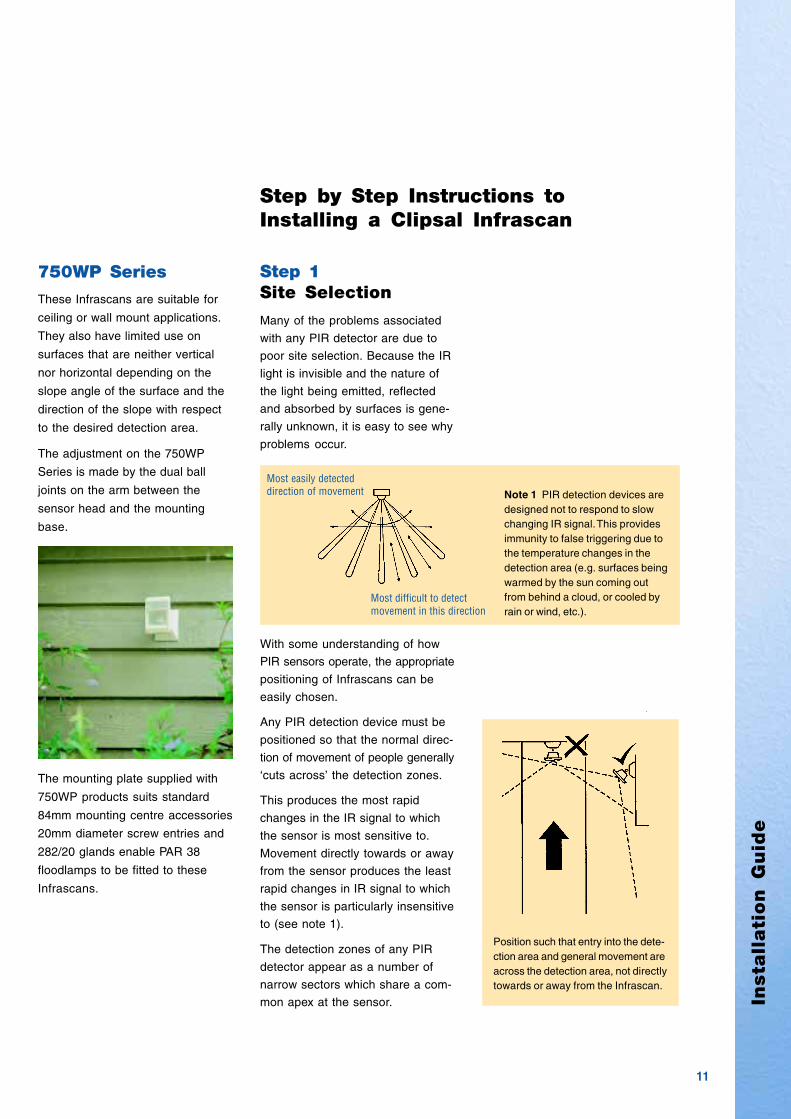
Step 1Site Selection
Many of the problems associated
with any PIR detector are due to
poor site selection. Because the IR
light is invisible and the nature of
the light being emitted, reflected
and absorbed by surfaces is gene-
rally unknown, it is easy to see why
problems occur.
With some understanding of how
PIR sensors operate, the appropriate
positioning of Infrascans can be
easily chosen.
Any PIR detection device must be
positioned so that the normal direc-
tion of movement of people generally
‘cuts across’ the detection zones.
This produces the most rapid
changes in the IR signal to which
the sensor is most sensitive to.
Movement directly towards or away
from the sensor produces the least
rapid changes in IR signal to which
the sensor is particularly insensitive
to (see note 1).
The detection zones of any PIR
detector appear as a number of
narrow sectors which share a com-
mon apex at the sensor.
Most easily detecteddirection of movement
Most difficult to detectmovement in this direction
Note 1 PIR detection devices aredesigned not to respond to slowchanging IR signal. This providesimmunity to false triggering due tothe temperature changes in thedetection area (e.g. surfaces beingwarmed by the sun coming outfrom behind a cloud, or cooled byrain or wind, etc.).
Step by Step Instructions toInstalling a Clipsal Infrascan
Position such that entry into the dete-ction area and general movement areacross the detection area, not directlytowards or away from the Infrascan.
The mounting plate supplied with
750WP products suits standard
84mm mounting centre accessories
20mm diameter screw entries and
282/20 glands enable PAR 38
floodlamps to be fitted to these
Infrascans.

12
Step 2General Assembly
Pass the flexible lead of the Infra-
scan through the cable gland and
assemble onto the mounting base.
Allow enough length of cable between
the mounting base and the detector
head for adjustment, then tighten
the gland. Fit the two threaded plugs
into the remaining apertures in the
mounting base. Fit the gasket to the
mounting base.
Gasket
Fit mounting base to surface to ensure adequate waterproofing
Waterproofing of the cableconnections is mandatory andis the responsibility of theinstaller. The entire electronicsenclosure is fully sealed at thetime of manufacture. A smallamount of silastic may also beused for weatherproofing.
Step 4Fitting the Infrascsan
Fit the Infrascan mounting base to
the chosen site with suitable
fasteners.
For the 750WP Series Infrascans,
fit the caps into the screw recesses,
ensuring that there is adequate
weather protection of the termina-
tions inside the mounting base.
Next, tighten both ball joint clamps
sufficiently to hold the detector
head in the appropriate position.
Step 3Wiring
Pass the wiring through a hole in
the wall or eave, (where the moun-
ting base is fitted) and terminate to
the end of the flexible lead of the
750WP Series Infrascan.
Step by Step Instructions toInstalling a Clipsal Infrascan
Pass lead through glandand fit to mounting base
Allow enough length
Fit 20mm diameterplugs to spare entries
General Assembly 751 Series
Insta
llati
on
Gu
ide
13
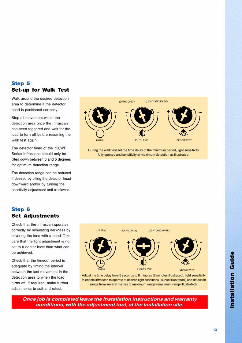
Step 5Set-up for Walk Test
Walk around the desired detection
area to determine if the detector
head is positioned correctly.
Stop all movement within the
detection area once the Infrascan
has been triggered and wait for the
load to turn off before resuming the
walk test again.
The detector head of the 750WP
Series Infrascans should only be
tilted down between 0 and 5 degrees
for optimum detection range.
The detection range can be reduced
if desired by tilting the detector head
downward and/or by turning the
sensitivity adjustment anti-clockwise.
LIGHT LEVEL SENSITIVITYTIMER
Step 6Set Adjustments
Check that the Infrascan operates
correctly by simulating darkness by
covering the lens with a hand. Take
care that the light adjustment is not
set to a darker level than what can
be achieved.
Check that the timeout period is
adequate by timing the interval
between the last movement in the
detection area to when the load
turns off. If required, make further
adjustments to suit and retest.
Once job is completed leave the installation instructions and warrantyconditions, with the adjustment tool, at the installation site.
LIGHT LEVEL SENSITIVITYTIMER
~
(~2 MIN)
Adjust the time delay from 5 seconds to 8 minutes (2 minutes illustrated), light sensitivityto enable Infrascan to operate at desired light conditions ( sunset illustrated ) and detection
range from several metres to maximum range (maximum range illustrated).
During the walk test set the time delay to the minimum period, light sensitivityfully opened and sensitivity at maximum detection as illustrated.
(LIGHT AND DARK)(DARK ONLY)
(LIGHT AND DARK)(DARK ONLY)

14
TypicalInstallations
751 Series
A typical installation for a single
indoor Infrascan is in a square or
rectangular room up to 6m by 6m.
The Infrascan should be fitted near
the wall that contains the main
entrance doorway, at the corner
away from the doorway.
VIEW
For square and near square rooms,
the Infrascan can simply be angled
at 45o from each of the walls at the
corner of the room. If there are two
entrance doorways on adjacent
walls, the Infrascan can be fitted at
the corner of those two walls.
If the entrance doorways are on
opposite sides of the room, install
the Infrascan opposite the wall
containing the doorway that can
tolerate detection past the doorway.
The Infrascan must be fitted rigidly
and tightly against a fixed mounting
surface. This is to prevent false trig-
gering from draughts and movement
of the Infrascan due to changes in air
pressure.
VIEW
VIEW
Light Traffic Area
Heavy Traffic Area
Position Infrascan on same wallas entrance doorway.
Fit Infrascan in corner betweenadjacent entrance doorways
Position Infrascan to minimisedetection from heavy traffic incorridor

Insta
llati
on
Gu
ide
15
ab
c
750WP SeriesFixing Location
A typical installation for a single
750WP Series Infrascan is outdoors,
covering a verandah, porch, pathway,
patio, driveway, etc. up to about
15m by 15m. If possible, choose a
position that is partially protected
from the sun and rain.
Even though the Infrascan is desig-
ned for long life with outdoor use,
the finish on the plastic components
will last even longer if protected
from the sun’s UV rays.
Providing partial cover from the rain
will ensure maximum sensitivity by
minimising the amount of rain droplets
that adhere to the detector window
(water will block out IR light).
If full coverage is required over the
rectangular or square area, the
Infrascan must be installed near
the corner of that area. The Infra-
scan position must be such that
most movement is across the front
of the Infrascan (tangential direction),
with minimal movement towards or
away from the Infrascan.
The detector head of the Infrascan
must be tilted down only slightly (5o
from vertical) for optimum range.
The detector head can be tilted
down further as a method of reducing
the detection range eg. to avoid
detection of distant pedestrians or
moving vehicles. The aspect of the
detector head (when viewed from
directly in front) must be kept vertical.
Position Infrascan at A or B but do not position at C
ac b
5O
Usual direction of movementthrough detection field
Tilt Infrascanfrom 0o to 5o
degrees foroptimum range.

16
Common Problems
One of the most common problems
is lack of sensitivity due to poor
positioning of the Infrascan.
The most common examples are
positioning an Infrascan outside,
above a main entrance door and
indoors at the end of a corridor.
The outdoor Infrascan solution is
relatively easy. The Infrascan would
be more appropriately positioned
on either side of the usual direction
of movement, as suggested by
positions A or B (as per previous
page)
The solution to adequate detection
for the indoor Infrascan is made
with consideration to the direction
of movement and entry points into
the corridor.
The Infrascan will always perform
better if it is positioned to one side
of the corridor as movement along
the length of the corridor will cross
the detection zones. If positioned
next to an end door, site the Infra-
scan on the door hinge side of the
corridor.
Consideration must be made (as
usual) that the Infrascan can not
view into adjacent rooms as move-
ment could be detected.
If the corridor is longer than 6 metres,
an additional Infrascan may be re-
quired at the other end or possibly
midway depending on the situation.
Obstructions
Choose a site that has no visual
obstructions between the Infrascan
and the desired detection area.
This includes gutters, facia boards,
down pipes, light fittings, trusses,
arches, doorways, cupboards,
plants, creepers, overhead cables,
glass windows, etc.
Mounting Height
Clipsal Infrascans have been desi-
gned for mounting onto a horizontal
or vertical surface at a height of
2.4m above the ground. If the ground
level is sloping, the 750WP Series
can be tilted to suit the slope of the
ground.
Mounting the Infrascan lower than
the recommended height will result
in reduced detection performance
with a noticeable reduction in the
sensitivity to movement directly
towards, or away from, the Infrascan.
Mounting the Infrascan higher than
the recommended height may result
in some improvements to aspects
of the detection capabilities, such
as increased range and sensitivity
to movement directly towards, or
away from, the Infrascan.
However, a reduction in sensitivity
in the detection area within several
metres of the Infrascan can result.
If mounting a 751 Series Infrascan
to a cathedral style (sloped) ceiling,
a spacer block may have to be
fabricated to achieve a horizontal
mounting surface. However, depen-
ding on the application, the range
detection performance of the 751
Series can actually be improved by
tilting it up to about 15o as shown
below (this will slightly compromise
close range performance).
Note that the bars in the detector
window, when viewed from directly
in front, must be vertical in all
installations.
Reduced closerange detection
Spacer block
751 Series installationon sloped ceiling
TypicalInstallations
Avoid mounting the detector nearobstructions such as downpipes

Insta
llati
on
Gu
ide
17
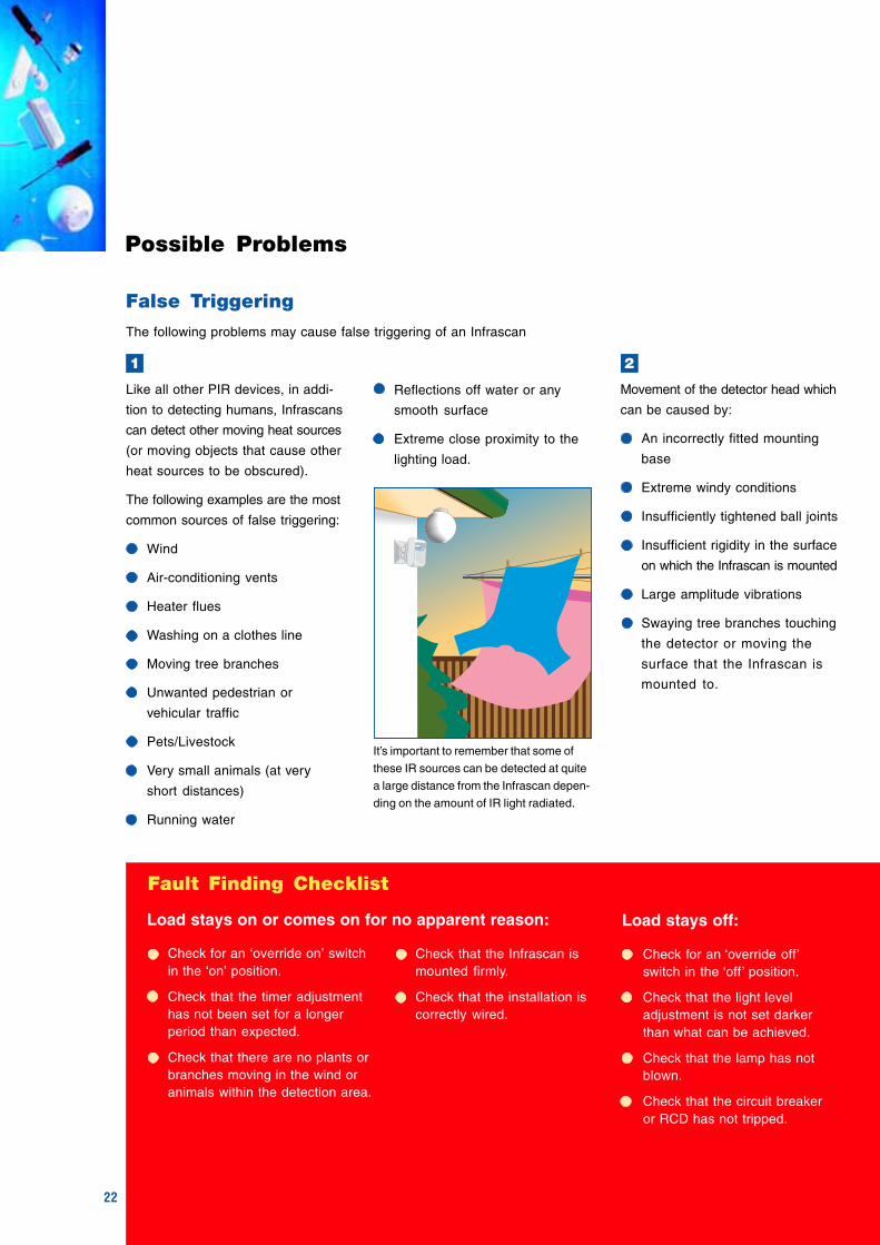
Reflectionand Transmission
IR light will reflect off all smooth
surfaces such as metal, paint,
varnish, glass, plastic, ceramic,
water and enamel finishes,
especially at acute angles.
These reflections may cause a
problem where the movement in
another room could cause the Infra-
scan to trigger. Even if there is no
direct line between the body move-
ment and the Infrascan, sufficient
IR energy can be reflected.
Note: There are very few materials
that IR light can actually pass
through. Even these materials have
to be quite thin to allow most of the
light through.
Power Up Sequence
When powering up an Infrascan for
the first time, it is normal for the
circuit to trigger the timer as the
detector circuitry stabilises.
Depending on the sensitivity setting
(750WP Series only) the settling
time may be several seconds to
around one minute (depending on
the model of Infrascan) plus the set
timeout period.
After this settling period, the Infrascan
is ready for operation. The load
usually comes on during this settling
period.
Glass and clear plastic, such as
PVC or polycarbonate, appear
totally opaque at these frequencies
and therefore do not allow this light
through at all.
It is also important to remember that
any netting or mesh will appear
partially transparent.
Consideration must be made to posi-
tioning an Infrascan when windows
and doors with mesh or wire screens
are used. These will be transparent
and could lead to false triggering of
the Infrascan, from the movement
on the other side of the mesh.
Power offTurn
power on
Settling period Normal operation
Light goes offfollowing settling
period
Approx. 1 minutueplus time delay
set on unit
Movement can be detectedthrough a wire mesh door.
Mirrors reflect IR light.

18
ElectricalWhen fitting a Clipsal Infrascan or
any other electronic accessory,
some precautions must be made
with the physical layout of the wiring
of the installation.
Because of the nature of the control
circuit, the current consumed by
the electronic circuitry is not a pure
sinusoidal current but consists of a
small amount of discontinuity (or
distortion).
This produces some very low level
harmonic (higher frequency) currents
that can extend up to about the AM
broadcast band. These harmonic cur-
rents do not produce any problems at
all with conventional wiring and when
all the connections are available.
However, problems may arise with
interference on weak AM band
radio station reception if a loop ante-
nna is formed by the mains wiring.
This can occur, for example, if there
is no neutral available at the point
of installation (ie. at, or near a switch)
when fitting a three wire product,
and a conductor run is made from
another location for the neutral.
If this wire is not run next to the
other current carrying conductors,
the loop that the current flows around
consists of a much larger area when
compared to using existing cable
with all the necessary conductors.
This forms a loop antenna which
improves the coupling of the un-
wanted harmonic components to
the radio receiver.
TypicalInstallations
HOUSE
FUSEBOX
A N
SMALL LOOP AREAINCOMINGMAINS
A N
N
L
A
N
A
HOUSE
FUSEBOX
A N
LARGE LOOP AREAINCOMINGMAINS
A N
N
L
A
N
A
TO OTHERDEVICES
Optimum Cable Layout Infrascan (R Version)
Non-Optimum Cable Layout Infrascan (R Version)

Insta
llati
on
Gu
ide
19
MultipleInfrascans
Implementation
The easiest way to connect more
than one Infrascan to a common
load is by using the 3 wire, relay
version (751R indoor/750WPR out-
door) and simply connecting all the
load terminals together to the load
circuit.
The C-Bus Infrascans can naturally
be configured to control a common
load circuit or almost any combina-
tion of circuits for each Infrascan if
desired.
It is possible for a two-wire Infrascan
to be connected to a common load
with other Infrascans but only with
the use of a contactor for each of
the two wire circuit Infrascans used.
When the 2 wire Infrascan switches
the solenoid of the contactor is ener-
gised closing the contact and enabling
power to the lighting circuit.
The use of more than one Infrascan
on the one lighting load circuit can
be for any of the following reasons
For covering a much larger area
than a single Infrascan can cover.
For covering adjacent areas
that are divided (eg. separated
by a corner of a building, trees,
trellis or different levels).
For increased detection capability
of the one area (eg. where excel-
lent sensitivity is required to all
directions of movement).LAMP
N
A
TWO WIREINFRASCAN
CONTACTOR
In this case it is preferable to create
additional load circuits (particularly
for applications in point 2 ). This will
result in easier setup and fault finding
of the installation and minimises any
nuisance with false triggering.
Recommendation
The recommendation is to use one
Infrascan wherever possible.
However, where more than one
Infrascan must control a common
load circuit, the recommendation is
to keep the number of Infrascans to
an absolute minimum, particularly if
the light level adjustment feature is
used (see possible problems overleaf).
Using 2 wire devices and contactors to control a common load
REPEAT FORADDITIONALTWO-WIREINFRASCANS
10A FUSE or MCB
1
2
3
20
Possible Problems
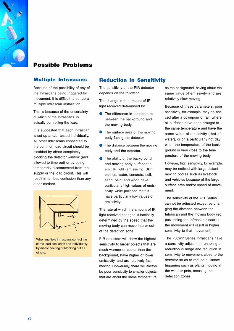
Multiple Infrascans
Because of the possibility of any of
the Infrascans being triggered by
movement, it is difficult to set up a
multiple Infrascan installation.
This is because of the uncertainty
of which of the Infrascans is
actually controlling the load.
It is suggested that each Infrascan
is set up and/or tested individually.
All other Infrascans connected to
the common load circuit should be
disabled by either completely
blocking the detector window (and
allowed to time out) or by being
temporarily disconnected from the
supply or the load circuit. This will
result in far less confusion than any
other method.
The sensitivity of the PIR detector
depends on the following:
The change in the amount of IR
light received determined by
The difference in temperature
between the background and
the moving body.
The surface area of the moving
body facing the detector.
The distance between the moving
body and the detector.
The ability of the background
and moving body surfaces to
emit IR light (emissivity). Skin,
clothes, water, concrete, soil,
sand, paint and wood have
particularly high values of emis-
sivity, while polished metals
have particularly low values of
emissivity.
The rate at which the amount of IR
light received changes is basically
determined by the speed that the
moving body can move into or out
of the detection zone.
PIR detectors will show the highest
sensitivity to larger objects that are
much warmer or cooler than the
background, have higher or lower
emissivity, and are relatively fast
moving. Conversely, there will always
be poor sensitivity to smaller objects
that are about the same temperature
as the background, having about the
same value of emissivity and are
relatively slow moving.
Because of these parameters, poor
sensitivity, for example, may be noti-
ced after a downpour of rain where
all surfaces have been brought to
the same temperature and have the
same value of emissivity (that of
water), or on a particularly hot day
when the temperature of the back-
ground is very close to the tem-
perature of the moving body.
However, high sensitivity, for example,
may be noticed with large distant
moving bodies such as livestock
and vehicles because of the large
surface area and/or speed of move-
ment.
The sensitivity of the 751 Series
cannot be adjusted except by chan-
ging the distance between the
Infrascan and the moving body (eg.
positioning the Infrascan closer to
the movement will result in higher
sensitivity to that movement).
The 750WP Series Infrascans have
a sensitivity adjustment enabling a
reduction in range and reduction in
sensitivity to movement close to the
detector so as to reduce nuisance
triggering such as plants moving in
the wind or pets, crossing the
detection zones.
When multiple Infrascans control thesame load, test each one individuallyby disconnecting or blocking out allothers.
Reduction In Sensitivity

Insta
llati
on
Gu
ide
21
As the lamp load is turned on by
the second Infrascan, the resulting
increase in the ambient light levels
can then cause the first Infrascan
to be disabled.
The remedy is difficult as the Infra-
scan must be positioned so that it
receives none or little of the light
from the lamp load that it controls.
This is in direct conflict with the
purpose of the Infrascan (ie. auto-
matic illumination of the detection
area).
To help overcome this problem, set
the light level threshold on all
Infrascans to quite a high light level
(above which the lamp load could
achieve at night).
This problem will then only occur
near that threshold (as the lighting
load will have little influence over
high natural light levels) and will
then only occur for a relatively short
period of the day. Additionally, the
Infrascans should be positioned so
that direct light from the lamp load
does not fall on the sensor window.
A complete solution to the problem
is to set all Infrascans to operate
at all light levels and then use a
separate sunset switch to control
a contactor. This contactor can be
used to isolate the lamp load from
the Infrascans when the natural
light levels are sufficient.
The sunset switch can then be
positioned well away from the areas
that are illuminated by the lamp load,
monitoring the natural light levels
only.
N
A
Infrascans(R Versions)
Light Level Threshold
Peculiar behaviour can be observed
with a common lighting load conne-
cted to several Infrascans.
Illumination from the lamp load can
disable the Infrascans that are not
triggered because of the artificial
increase in the ambient light levels
(above the preset light level of each
Infrascan).
For example, if a person moves out
of the detection area of one Infrascan
to the detection area of a second
Infrascan where both areas are
illuminated by the one common
lighting load, the second Infrascan
may be disabled because of the
increase in the ambient light level.
This will allow the timer of the first
Infrascan to timeout, therefore
turning the lamps off, even if there
is movement in front of the second
Infrascan. Because the lamp load
had been turned off, this then lowers
the ambient light level below the
threshold set by the second unit,
thus now enabling it to respond to
any possible movement.
If there is movement in the second
area at the time the first Infrascan
times out, the lamp load will only
stay off for less than one second as
the second Infrascan is enabled to
detect the movement. It is important
to note that the lamp load will remain
off if there is no movement at that
moment, even if there was move-
ment in the second detection area
just moments prior to the lamp load
turning off.
Light Level Threshold With Multiple Infrascans
Load
Contactor
SunsetSwitch
22
False Triggering
The following problems may cause false triggering of an Infrascan
Possible Problems
Like all other PIR devices, in addi-
tion to detecting humans, Infrascans
can detect other moving heat sources
(or moving objects that cause other
heat sources to be obscured).
The following examples are the most
common sources of false triggering:
Wind
Air-conditioning vents
Heater flues
Washing on a clothes line
Moving tree branches
Unwanted pedestrian or
vehicular traffic
Pets/Livestock
Very small animals (at very
short distances)
Running water
1 2
Movement of the detector head which
can be caused by:
An incorrectly fitted mounting
base
Extreme windy conditions
Insufficiently tightened ball joints
Insufficient rigidity in the surface
on which the Infrascan is mounted
Large amplitude vibrations
Swaying tree branches touching
the detector or moving the
surface that the Infrascan is
mounted to.
Reflections off water or any
smooth surface
Extreme close proximity to the
lighting load.
Fault Finding Checklist
Check for an ‘override on’ switchin the ‘on’ position.
Check that the timer adjustmenthas not been set for a longerperiod than expected.
Check that there are no plants orbranches moving in the wind oranimals within the detection area.
Check that the Infrascan ismounted firmly.
Check that the installation iscorrectly wired.
Check for an ‘override off’switch in the ‘off’ position.
Check that the light leveladjustment is not set darkerthan what can be achieved.
Check that the lamp has notblown.
Check that the circuit breakeror RCD has not tripped.
Load stays on or comes on for no apparent reason: Load stays off:
It’s important to remember that some of
these IR sources can be detected at quite
a large distance from the Infrascan depen-
ding on the amount of IR light radiated.

Insta
llati
on
Gu
ide
23
the capacitor and the Infrascan
terminals to a minimum.
Y class capacitors should only be
used in this application:
3
The least likely cause is extreme
electrical interference (RFI) that
can be conducted down the mains
supply cable. This can be caused
by fluorescent lamps or motors
starting, faulty insulation or RF
transmitters.
Clipsal Infrascans have been desi-
gned to suppress most RFI induced
signals and incorporate a special
circuit that rejects unwanted signals.
In the rare event that the false trig-
gers are due to RFI, suppression
capacitors can be connected to
improve this problem.
This is done by connecting one Y
class 250V a.c. min. rated capacitor
(from 100pF to 10nF) directly across
the active and neutral connections
at each Infrascan, keeping the
length of the conductor between
ACTIVE
LOAD
Check that there is poweravailable at the Infrascan.
Check that the sensitivityadjustment is not set too low.
Check that the installation iscorrectly wired (broken conne-ction or wire).
Check that the detector windowis not obscured.
Check that the lamp load is nottoo close to the detection window.
Check that the power factorcorrection capacitors are fittedto gas discharge lamps (eg.fluorescent lamps).
Check that there are no plantsor branches moving in the windor animals within the detectionarea.
Check that the installation iscorrectly wired and that theinsulation hasn’t broken down.
Check that the load has notbeen connected directly to atwo wire circuit in a multipleInfrascan installation.
Load turns on, off, on and off, etc:
NEUTRAL(Three Wire)LOOP(Two Wire)
The Infrascan must be mounted to a rigid
surface with all the mechanical adjustments
tightened to minimise movement.
LOAD
A
N
Y-CLASSCAPACITOR INFRASCAN

24
LoadRecommendations
Two Wire CircuitLoads
The two wire circuit will control a
large variety of loads including highly
inductive or capacitive loads up to
the maximum current rating of the
product. The electronic switching
device used (triac), is an extremely
rugged type that can withstand the
high inrush currents of capacitive
loads.
For some loads, special considera-
tions must be made for the correct
operation of the two wire circuit.
The two wire circuit operates with
the small leakage current that is
passed through the load in the off
state. In the on state, it operates
from the low level voltage that is
dropped across the switching devices.
For these reasons, very small loads
may have a significant voltage drop
across them, in the off state, because
of the leakage current. This may
cause a lamp load to partially illu-
minate (particularly if a gas discharge
type, eg. neon or mercury vapour)
or the armature of a small relay
load to vibrate.
The minimum load current has
been set at about ten times the
maximum two wire circuit leakage
current to minimise these effects.
Fluorescent lamps will require
power factor correction capacitors
to be fitted to provide a current
path for the two wire circuit in the
off state. Some difficulty may be
experienced with correct operation
of a two wire circuit when using
small PL type lamp loads,
particularly the very low power and
electronic variety.
These types of lamps do not normally
have a provision for power factor
correction capacitors, so a capa-
citor may have to be fitted to the
lamp fitting, or alternatively, a resis-
tive load (eg. tungsten lamp) can
be connected in parallel with the PL
lamp(s).
750WP / 751
A
N
MULTIPLE 750WPR/751R INFRASCAN POSSIBLE ON ONE LOAD CIRCUIT
Brown10A Fuse or MCB
750WPR / 751R
A
N
Brown
White
10A Fuse or MCB
ONE 750WP/751 INFRASCAN PER LOAD CIRCUIT
White
Blue
Three Wire Circuit
The relay fitted to the Clipsal
Infrascans and C-Bus relay units
can be used with any type of load
up to the maximum continuous
current rating of the product.
It is especially suited for long life
use with loads that have high inrush
currents (power factor correction
capacitors fitted or tungsten fila-
ments). It is also suitable for use
with highly inductive loads where
there is a large amount of back
EMF produced when turning off.
Insta
llati
on
Gu
ide
25
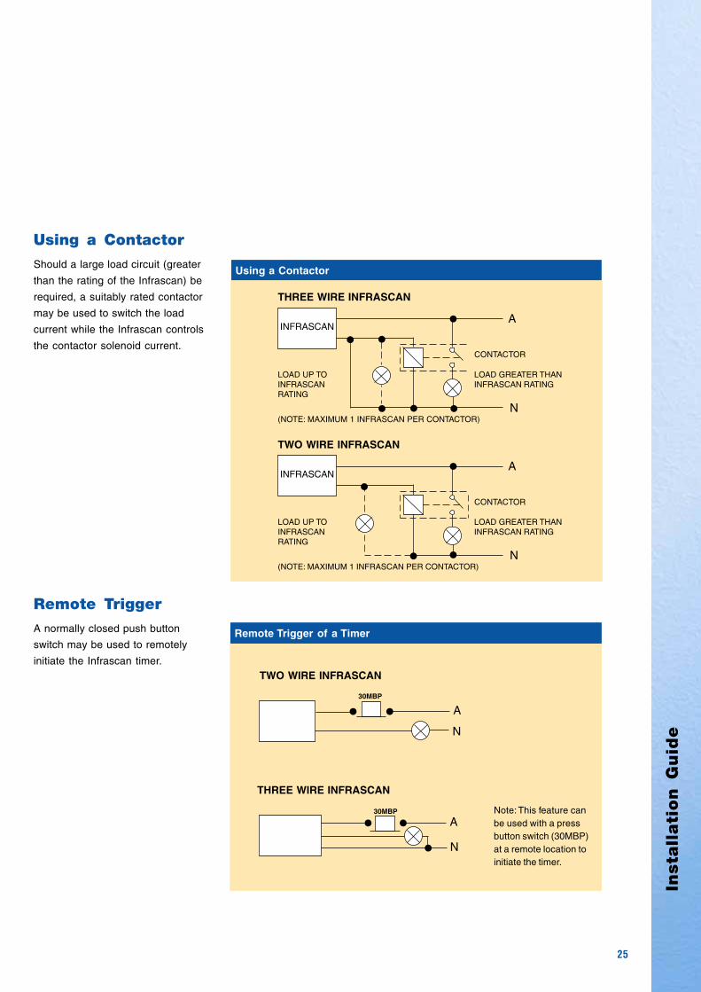
Using a Contactor
Should a large load circuit (greater
than the rating of the Infrascan) be
required, a suitably rated contactor
may be used to switch the load
current while the Infrascan controls
the contactor solenoid current.
Remote Trigger of a Timer
•30MBP• A
N•
• • A
N
30MBP
Note: This feature canbe used with a pressbutton switch (30MBP)at a remote location toinitiate the timer.
THREE WIRE INFRASCAN
TWO WIRE INFRASCAN
Using a Contactor
•
• A
N
INFRASCAN
CONTACTOR
LOAD GREATER THANINFRASCAN RATING
LOAD UP TOINFRASCANRATING
(NOTE: MAXIMUM 1 INFRASCAN PER CONTACTOR)
TWO WIRE INFRASCAN
• A
N
INFRASCAN
CONTACTOR
LOAD GREATER THANINFRASCAN RATING
LOAD UP TOINFRASCANRATING
THREE WIRE INFRASCAN
•
•
••
•
Remote Trigger
A normally closed push button
switch may be used to remotely
initiate the Infrascan timer.
•
•
(NOTE: MAXIMUM 1 INFRASCAN PER CONTACTOR)

26
LoadRecommendations
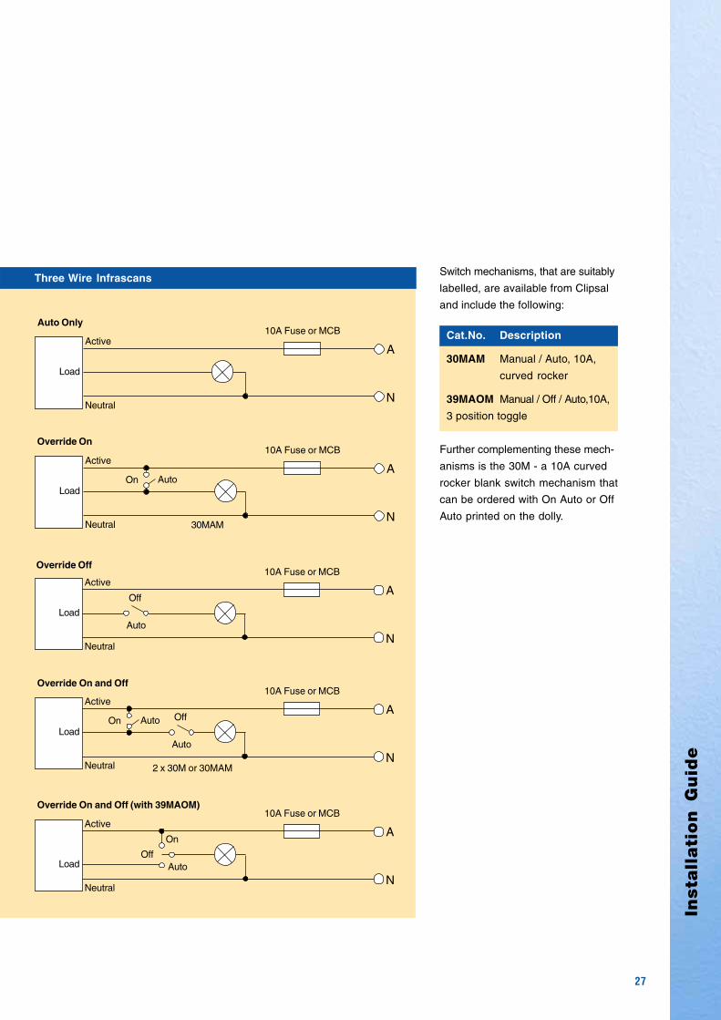
Override Facilities
Some installations may require an
override on and/or an override off
facility. These facilities allow the user
to select an appropriate mode of
operation to enable the load to be
turned on or off.
It is essential that any override
switch or switches are appropriately
labelled, as it is otherwise difficult to
determine the setting of the switches
(eg. for an override switch, the load
can be in the same state in both
positions). Also, because of the un-
certainty of the state of the override
switch, two way (or multiway) over-
ride switching is not recommended.
Note: The use of an override on or
override off switch with a two wire
Infrascan (or, incorrectly, on the
active line of a relay Infrascan) will
result in the normal power up
sequence whenever operation is
returned to the automatic mode (ie.
the load will turn on for the settling
time plus the set timeout period).
Two Wire Infrascans
N
A10A Fuse or MCB
Active
Load
Auto Only
N
A10A Fuse or MCB
Active
Load
On Auto
30MAM
N
A10A Fuse or MCB
Load
Off
Auto
Active
Override Off
Override On
N
A10A Fuse or MCB
Active
Load
Override On and Off Off
AutoOn Auto
2 x 30M or 30MAM
N
Active
Load
Override On and Off (with 39MAOM)
39MAOM
A
10A Fuse or MCB
OffAuto
On
Insta
llati
on
Gu
ide
27
Three Wire Infrascans
N
Active
Neutral
Auto Only
Override Off
Override On
Override On and Off
Override On and Off (with 39MAOM)
A
10A Fuse or MCB
Load
N
Active
Neutral
A
10A Fuse or MCB
LoadAutoOn
30MAM
N
Active
Neutral
A
10A Fuse or MCB
LoadAuto
Off
N
Active
Neutral
A
10A Fuse or MCB
LoadAuto
OffAutoOn
2 x 30M or 30MAM
NNeutral
A
10A Fuse or MCB
Load
Active
On
AutoOff
Switch mechanisms, that are suitably
labelled, are available from Clipsal
and include the following:
Cat.No. Description
30MAM Manual / Auto, 10A,
curved rocker
39MAOM Manual / Off / Auto,10A,
3 position toggle
Further complementing these mech-
anisms is the 30M - a 10A curved
rocker blank switch mechanism that
can be ordered with On Auto or Off
Auto printed on the dolly.

28
Technical Data
751 Series (non C-Bus)
Catalogue Numbers 750WP, 750WPR
Input Voltage 200 - 265V a.c., 50Hz
Maximum Load Current 750WP 5A750WPR 10A
Minimum Load 20mA (750WP only)
Detection Method Passive infrared detection of thermal radiation
Compatible Lighting Incandescent or fluorescent
Time Delay 5 secs to 8 mins, (nominal), infinitely variable within this range
Ambient Light Level Adjustment From full daylight to below 1 Lux (darken room)
Detection Area 18m x 110o
Number of Detection Zones 18 long range
16 intermediate range
10 short range
4 ultra short range
Installation Height 2.4m optimum mounting height.Sensor head vertical.
Leakage Current in the OFF state 2.0mA (max) @ 25oC (750WP only) Note 1
Operating Temperature Range 0oC to 50oC
Standard Colour GY - Grey
750WP Series (non C-Bus)
Note 1.
The two wire devices derive their
power through the load, therefore
the load is never completely
unenergised when off, as with
switch contacts.
Note 2.
These are typical specifications.
there may be noticeable differences
in the range due to differing conditions
such as background temperature,
speed of movement, types of
clothing worn etc.
Catalogue Numbers 751, 751R
Input Voltage 192 - 264V a.c., 50Hz
Maximum Load Current 751 2A751R 10A
Minimum Load 20mA (751 only)
Detection Method Passive infrared detection of thermal radiation
Compatible Lighting Incandescent or fluorescent
Time Delay 5 secs to 20 mins (nominal), infinitely variable within this range
Ambient Light Level Adjustment From full daylight to below 1 Lux (darken room)
Detection Area 6 x 6 metres, 90 degrees from sensor head. Sensor head rotatable 120 degrees when installed.
Installation Height 2.4m optimum mounting height. Unit may be wall mounted. Other installation heights mayresult in decreased scanning areas.
Leakage Current in the OFF state 2.0mA (max) @ 25oC (751 only) Note 1
Operating Temperature Range 0oC to 40oC
Overall Dimensions 100mm diameter by 57mm high
Mounting Centres 60.3, 84 and 50mm
Standard Colour WE - White Electric
Terminals 751 Line, load, 2 x loop accepts 3 x 2.5mm2 cable
751R Line, load, neutral, loop Accepts 3 x 2.5mm2 cable

750WP & 751 Series
Your comprehensive guideto installing Clipsal Infrascans
Inst
alla
tion
Gu
ide
Products of Gerard Industries Pty LtdABN 27 007 873 529
Head Office12 Park Terrace, BowdenSouth Australia 5007Telephone (08) 8269 0511Facsimile (08) 8340 1724Internet clipsal.comE-Mail [email protected]
Offices in all StatesNSW Sydney (02) 9794 9200
Albury (02) 6041 2377
VIC Melbourne (03) 9207 3200Country Areas 1800 653 893
QLD Brisbane (07) 3244 7444Townsville (07) 4729 3333
SA Adelaide (08) 8269 0555
WA Perth (08) 9442 4444
TAS Hobart (03) 6272 3177Launceston (03) 6343 5900
NT Darwin (08) 8947 0278
Area RepresentativesNSW Albury (02) 6041 2377
Central Coast 0418 430 361Coffs Harbour 0418 653 183Dubbo 0418 822 564Newcastle 0407 298 792
0418 434 1690418 686 040
South West Sydney 0419 868 353Tamworth 0417 714 339Wagga Wagga 0418 578 903Wollongong 0418 423 581
ACT Canberra 0419 238 824Canberra/Goulburn 0418 164 070Canberra/Yass 0419 847 732
VIC Bendigo 0418 570 213Geelong 0418 527 233Gippsland 0418 512 680Western Victoria 0419 380 444
QLD Cairns 0418 773 254Gold Coast 0418 765 459Mackay 0418 752 134Maryborough 0418 664 338Northern Rivers 0418 768 902Rockhampton 0418 794 711Sunshine Coast 0418 711 786Toowoomba 0418 746 311Townsville 0418 180 372
WA Bunbury 0418 931 684Kalgoorlie & 0417 928 981Eastern Gold FieldsKarratha 0418 937 249
SA Riverland/Mildura/ 0418 596 145Broken Hill
Gerard Industries Pty Ltd reserves the right to changespecifications, modify designs and discontinue itemswithout incurring obligation and whilst every effort ismade to ensure that descriptions, specifications andother information in this catalogue are correct, nowarranty is given in respect thereof and the companyshall not be liable for any error therein.
O/N 850-462 OCT 01/02
©Copyright Gerard Industries Pty LtdPrinted by Custom Press Pty Ltd (08) 8346 7999
You can find this brochure and manyothers online in PDF format at:clipsal.comFollow the links off the home page oraccess the following page directly:clipsal.com/wat_lib_pdf.cfm
clipsal.com
International EnquiriesHead Office Export DepartmentTelephone + 61 8 8269 0587Facsimile + 61 8 8340 7350E-Mail [email protected]
New ZealandClipsal Industries (NZ) Ltd (Auckland)
Telephone (09) 576 3403Facsimile (09) 576 1015E-Mail [email protected]
Customer ServiceFree Fax (0508) 250 305Auckland/Mobile Phone (09) 572 0014Free Phone (0508) CLIPSAL
2547725
clipsal.com


![2012 Race 1 V8 Supercars Clipsal 500 Adelaide [Adelaide Clipsal]](https://img.pdfslide.net/doc/110x75/55c65bb9bb61eb884d8b482a/2012-race-1-v8-supercars-clipsal-500-adelaide-adelaide-clipsal.jpg)


![2005 V8 Supercars - Adelaide Clipsal 500 - Race 2 - Full Race [Adelaide Clipsal]](https://img.pdfslide.net/doc/110x75/55d25b8ebb61eb74478b46c1/2005-v8-supercars-adelaide-clipsal-500-race-2-full-race-adelaide-clipsal.jpg)
![Cold Chisel To Rock The 2015 Clipsal 500 Adelaide [2015 Clipsal 500]](https://img.pdfslide.net/doc/110x75/58edabcf1a28aba4088b4607/cold-chisel-to-rock-the-2015-clipsal-500-adelaide-2015-clipsal-500.jpg)

![Cold Chisel To Rock The 2015 Clipsal 500 Adelaide [2015 Clipsal]](https://img.pdfslide.net/doc/110x75/55c37b9ebb61eb6b5e8b469a/cold-chisel-to-rock-the-2015-clipsal-500-adelaide-2015-clipsal.jpg)


