Embed Size (px)
Citation preview

Climate solutions
VE
NT
ILC
ON
VE
TT
OR
E S
TA
ND
AR
D
CO
N M
OT
OR
E A
D IN
DU
ZIO
NE
SV
S
TA
ND
AR
D F
AN
CO
IL U
NIT
EQ
UIP
PE
D W
ITH
IND
UC
TIO
N T
YP
E M
OT
OR

I dati contenuti nel presente catalogo possono essere cambiati senza obbligo di preavviso. All specifications are subject to change without notice.
0 INTRODUZIONE
SV
INTRODUCTIONS SV
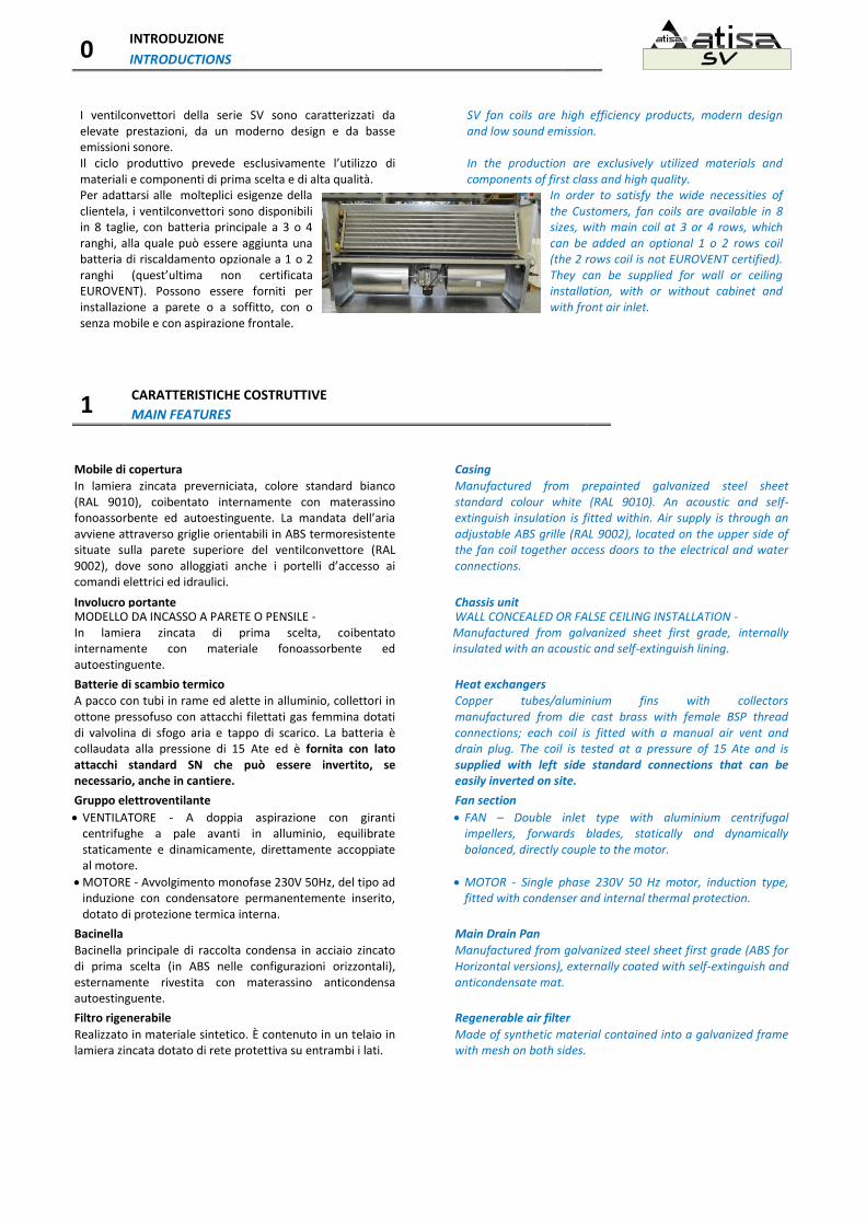
I ventilconvettori della serie SV sono caratterizzati da elevate prestazioni, da un moderno design e da basse emissioni sonore. Il ciclo produttivo prevede esclusivamente l’utilizzo di materiali e componenti di prima scelta e di alta qualità.
SV fan coils are high efficiency products, modern design and low sound emission. In the production are exclusively utilized materials and components of first class and high quality.
Per adattarsi alle molteplici esigenze della clientela, i ventilconvettori sono disponibili in 8 taglie, con batteria principale a 3 o 4 ranghi, alla quale può essere aggiunta una batteria di riscaldamento opzionale a 1 o 2 ranghi (quest’ultima non certificata EUROVENT). Possono essere forniti per installazione a parete o a soffitto, con o senza mobile e con aspirazione frontale.
In order to satisfy the wide necessities of the Customers, fan coils are available in 8 sizes, with main coil at 3 or 4 rows, which can be added an optional 1 o 2 rows coil (the 2 rows coil is not EUROVENT certified). They can be supplied for wall or ceiling installation, with or without cabinet and with front air inlet.
1 CARATTERISTICHE COSTRUTTIVE
MAIN FEATURES
Mobile di copertura Casing
In lamiera zincata preverniciata, colore standard bianco (RAL 9010), coibentato internamente con materassino fonoassorbente ed autoestinguente. La mandata dell’aria avviene attraverso griglie orientabili in ABS termoresistente situate sulla parete superiore del ventilconvettore (RAL 9002), dove sono alloggiati anche i portelli d’accesso ai comandi elettrici ed idraulici.
Manufactured from prepainted galvanized steel sheet standard colour white (RAL 9010). An acoustic and self-extinguish insulation is fitted within. Air supply is through an adjustable ABS grille (RAL 9002), located on the upper side of the fan coil together access doors to the electrical and water connections.
Involucro portante Chassis unit MODELLO DA INCASSO A PARETE O PENSILE - In lamiera zincata di prima scelta, coibentato internamente con materiale fonoassorbente ed autoestinguente.
WALL CONCEALED OR FALSE CEILING INSTALLATION - Manufactured from galvanized sheet first grade, internally insulated with an acoustic and self-extinguish lining.
Batterie di scambio termico Heat exchangers
A pacco con tubi in rame ed alette in alluminio, collettori in ottone pressofuso con attacchi filettati gas femmina dotati di valvolina di sfogo aria e tappo di scarico. La batteria è collaudata alla pressione di 15 Ate ed è fornita con lato attacchi standard SN che può essere invertito, se necessario, anche in cantiere.
Copper tubes/aluminium fins with collectors manufactured from die cast brass with female BSP thread connections; each coil is fitted with a manual air vent and drain plug. The coil is tested at a pressure of 15 Ate and is supplied with left side standard connections that can be easily inverted on site.
Gruppo elettroventilante Fan section
VENTILATORE - A doppia aspirazione con giranti centrifughe a pale avanti in alluminio, equilibrate staticamente e dinamicamente, direttamente accoppiate al motore.
FAN – Double inlet type with aluminium centrifugal impellers, forwards blades, statically and dynamically balanced, directly couple to the motor.
MOTORE - Avvolgimento monofase 230V 50Hz, del tipo ad induzione con condensatore permanentemente inserito, dotato di protezione termica interna.
MOTOR - Single phase 230V 50 Hz motor, induction type, fitted with condenser and internal thermal protection.
Bacinella Main Drain Pan
Bacinella principale di raccolta condensa in acciaio zincato di prima scelta (in ABS nelle configurazioni orizzontali), esternamente rivestita con materassino anticondensa autoestinguente.
Manufactured from galvanized steel sheet first grade (ABS for Horizontal versions), externally coated with self-extinguish and anticondensate mat.
Filtro rigenerabile Regenerable air filter
Realizzato in materiale sintetico. È contenuto in un telaio in lamiera zincata dotato di rete protettiva su entrambi i lati.
Made of synthetic material contained into a galvanized frame with mesh on both sides.
2 IDENTIFICAZIONE, VERSIONI E LATO ATTACCHI IDRAULICI
IDENTIFICATION CODE, VERSIONS AND HYDRAULIC CONNECTIONS SIDE SV
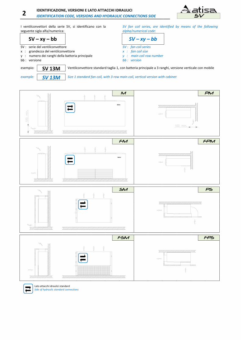
I ventilconvettori della serie SV, si identificano con la seguente sigla alfa/numerica:
SV fan coil series, are identified by means of the following alpha/numerical code:
SV – xy – bb
SV – xy – bb
SV : serie del ventilconvettore x : grandezza del ventilconvettore y : numero dei ranghi della batteria principale bb : versione
SV : fan coil series x : fan coil size y : main coil row number bb : version
esempio: SV 13M Ventilconvettore standard taglia 1, con batteria principale a 3 ranghi, versione verticale con mobile example: SV 13M Size 1 standard fan coil, with 3 row main coil, vertical version with cabinet
M PM
FM FPM
SM PS
FSM
FPS
Lato attacchi idraulici standard Side of hydraulic standard connections

3 PRESTAZIONI
PERFORMANCES SV
Prestazioni con batteria PRINCIPALE - Performances with MAIN coil
MODELLI - MODELS 13 14 23 24 33 34 43 44 53 54 63 64 73 74 83 84
Portata aria
m³/h
MIN 190 190 230 230 330 330 450 450 660 660 750 750 880 880 1010 1010
Air flow MED 240 240 290 290 440 440 610 610 750 750 990 990 980 980 1440 1440
MAX 280 280 400 400 660 660 720 720 990 990 1170 1170 1280 1280 1690 1690
Assorbimento elett.
W
MIN 29 27 34 23 35 37 41 45 124 123 139 137 132 119 159 134
Absorbed power MED 35 35 45 29 45 48 64 70 139 137 175 174 135 133 212 207
MAX 43 43 61 41 73 76 87 84 175 174 204 201 185 182 260 256
Livello di potenza
dB(A)
MIN 40 40 38 38 37 37 45 46 48 49 51 53 51 53 54 55
sonora (ISO 3741) MED 45 46 43 44 43 43 52 53 51 53 58 59 54 55 63 63
Sound power level MAX 49 50 51 51 51 51 56 57 58 59 61 63 61 62 67 67
Rese termiche in RAFFREDDAMENTO - COOLING capacities
Temperatura aria: 27°C d.b. - 19°C w.b.
Temperatura acqua: entrata 7°C
uscita 12°C
Air temperature: Water temperature: inlet outlet
Potenza totale*
kW
MIN 1.01 1.13 1.28 1.41 2.03 2.09 2.88 3.23 3.96 4.10 4.26 4.32 5.15 5.28 5.67 5.73
Total cooling capac. MED 1.24 1.39 1.62 1.78 2.55 2.65 3.58 4.13 4.52 4.56 5.19 5.53 5.43 5.85 7.39 7.75
MAX 1.36 1.52 2.11 2.31 3.23 3.53 3.98 4.62 5.51 5.84 5.77 6.30 6.77 7.35 8.59 9.22
Potenza sensibile**
kW
MIN 0.75 0.83 1.02 1.05 1.48 1.52 2.10 2.27 2.84 3.16 3.27 3.29 3.79 4.00 4.20 4.33
Sensible capacity MED 0.93 1.03 1.28 1.35 1.89 1.95 2.65 2.93 3.27 3.52 4.06 4.26 4.32 4.46 5.61 5.98
MAX 1.03 1.13 1.69 1.88 2.45 2.62 2.98 3.31 4.06 4.56 4.56 4.90 5.50 5.68 6.60 7.19
p acqua
kPa
MIN 6.3 1.7 5.7 3.8 6.1 8.5 10.0 14.7 20.7 10.6 23.3 12.9 11.8 11.9 14.1 14.1
p water MED 9.0 2.3 8.6 6.1 9.6 13.6 16.8 23.0 26.2 12.9 33.5 20.4 14.8 14.5 23.2 25.0
MAX 10.8 2.7 13.9 11.5 14.6 22.8 20.1 28.2 37.7 20.4 41.7 26.0 22.3 22.5 30.7 34.6
*Potenza totale = Potenza totale reale – Assorbimento elettrico Total cooling capacity = Real total cooling capacity – Absorbed power **Potenza sensibile = Potenza sensibile reale – Assorbimento elettrico Sensible capacity = Real sensible capacity - Absorbed power
Rese termiche in RISCALDAMENTO batteria principale – Main coil HEATING capacities
Temperatura aria: 20°C
Temperatura acqua: entrata 45°C
uscita 40°C
Air temperature: Water temperature: inlet outlet
Potenza termica
kW
MIN 1.22 1.36 1.64 1.74 2.31 2.50 2.95 3.27 4.37 4.81 4.84 5.37 5.55 6.21 6.18 6.97
Heating capacity MED 1.48 1.66 1.97 2.13 2.90 3.21 3.73 4.22 4.84 5.37 6.00 6.76 6.09 6.80 8.13 9.29
MAX 1.67 1.89 2.52 2.79 3.96 4.50 4.23 4.83 6.00 6.76 6.90 7.75 7.75 8.46 9.22 10.54
p acqua
kPa
MIN 7.6 2.0 6.0 3.1 5.7 7.9 9.0 13.0 13.8 10.1 16.6 12.4 11.3 12.1 13.9 15.4
p water MED 11.8 2.7 8.6 4.6 9.0 12.6 15.5 20.5 16.6 12.4 24.6 19.0 13.6 14.4 23.1 26.6
MAX 13.2 3.3 13.7 8.0 15.2 22.7 19.1 26.1 24.6 19.0 32.4 24.5 21.2 21.9 29.1 33.6
Rese termiche in RISCALDAMENTO batteria ausiliaria ad un rango (PX) - One row additional coil (PX) HEATING capacities
Temperatura aria: 20°C
Temperatura acqua: entrata 65°C
uscita 55°C
Air temperature: Water temperature: inlet outlet
Potenza termica
kW
MIN 0.96 1.37 1.96 2.40 3.66 3.98 4.59 5.01
Heating capacity MED 1.03 1.59 2.37 2.91 3.98 4.75 4.91 6.24
MAX 1.13 1.96 3.06 3.23 4.75 5.27 5.81 6.88
p acqua
kPa
MIN 1.5 3.8 8.8 12.4 13.0 16.6 9.7 27.5
p water MED 2.0 4.9 12.1 17.4 15.2 22.5 11.0 40.6
MAX 2.4 6.9 18.9 20.7 20.6 27.2 15.6 48.2
4 DIMENSIONI D’INGOMBRO E PESI
DIMENSIONS AND WEIGHTS SV
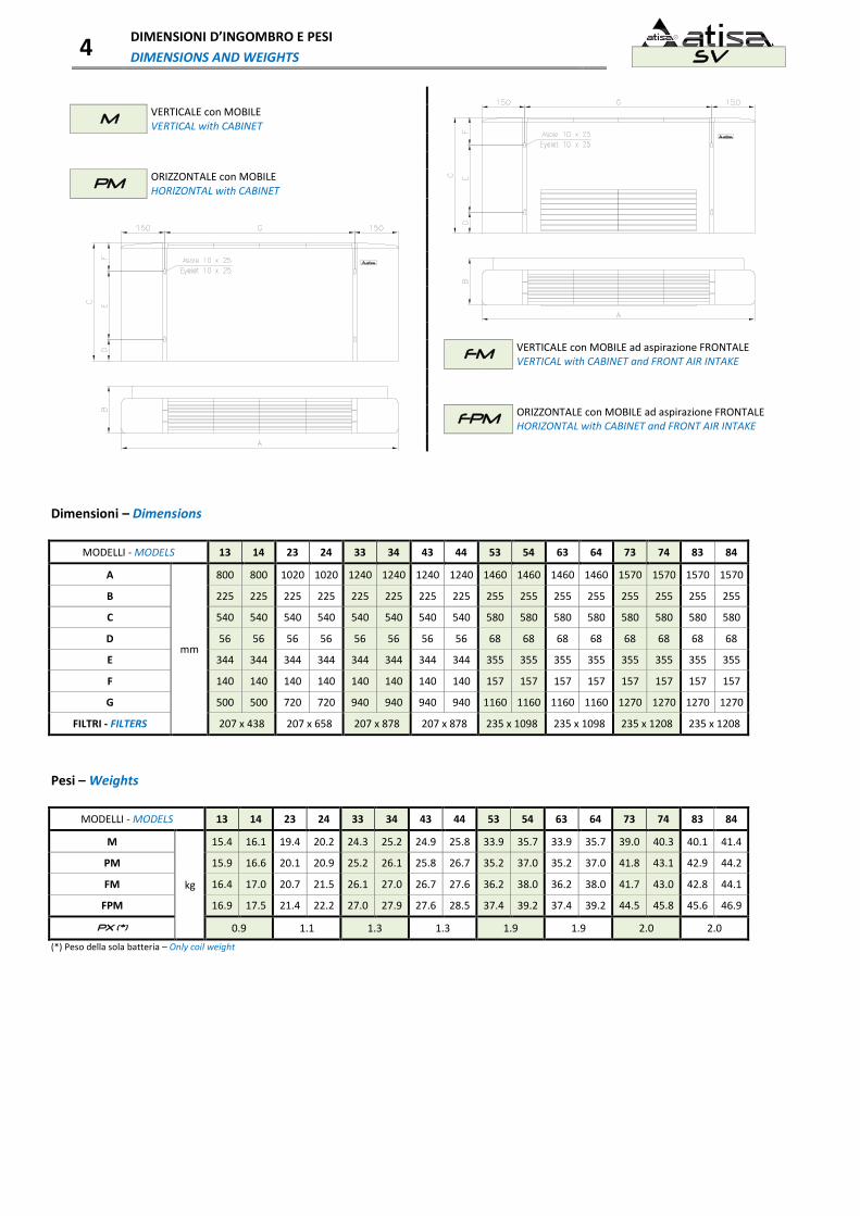
M VERTICALE con MOBILE VERTICAL with CABINET
PM ORIZZONTALE con MOBILE HORIZONTAL with CABINET
FM VERTICALE con MOBILE ad aspirazione FRONTALE VERTICAL with CABINET and FRONT AIR INTAKE
FPM ORIZZONTALE con MOBILE ad aspirazione FRONTALE HORIZONTAL with CABINET and FRONT AIR INTAKE
Dimensioni – Dimensions
MODELLI - MODELS 13 14 23 24 33 34 43 44 53 54 63 64 73 74 83 84
A
mm
800 800 1020 1020 1240 1240 1240 1240 1460 1460 1460 1460 1570 1570 1570 1570
B 225 225 225 225 225 225 225 225 255 255 255 255 255 255 255 255
C 540 540 540 540 540 540 540 540 580 580 580 580 580 580 580 580
D 56 56 56 56 56 56 56 56 68 68 68 68 68 68 68 68
E 344 344 344 344 344 344 344 344 355 355 355 355 355 355 355 355
F 140 140 140 140 140 140 140 140 157 157 157 157 157 157 157 157
G 500 500 720 720 940 940 940 940 1160 1160 1160 1160 1270 1270 1270 1270
FILTRI - FILTERS 207 x 438 207 x 658 207 x 878 207 x 878 235 x 1098 235 x 1098 235 x 1208 235 x 1208
Pesi – Weights
MODELLI - MODELS 13 14 23 24 33 34 43 44 53 54 63 64 73 74 83 84
M
kg
15.4 16.1 19.4 20.2 24.3 25.2 24.9 25.8 33.9 35.7 33.9 35.7 39.0 40.3 40.1 41.4
PM 15.9 16.6 20.1 20.9 25.2 26.1 25.8 26.7 35.2 37.0 35.2 37.0 41.8 43.1 42.9 44.2
FM 16.4 17.0 20.7 21.5 26.1 27.0 26.7 27.6 36.2 38.0 36.2 38.0 41.7 43.0 42.8 44.1
FPM 16.9 17.5 21.4 22.2 27.0 27.9 27.6 28.5 37.4 39.2 37.4 39.2 44.5 45.8 45.6 46.9
PX (*) 0.9 1.1 1.3 1.3 1.9 1.9 2.0 2.0
(*) Peso della sola batteria – Only coil weight

4 DIMENSIONI D’INGOMBRO E PESI
DIMENSIONS AND WEIGHTS SV
SM VERTICALE senza MOBILE VERTICAL without CABINET
PS ORIZZONTALE senza MOBILE HORIZONTAL without CABINET
FSM VERTICALE senza MOBILE ad aspirazione FRONTALE VERTICAL without CABINET and FRONT AIR INTAKE
FPS ORIZZONTALE senza MOBILE ad aspirazione FRONTALE HORIZONTAL without CABINET and FRONT AIR INTAKE
Dimensioni – Dimensions
MODELLI - MODELS 13 14 23 24 33 34 43 44 53 54 63 64 73 74 83 84
A
mm
480 480 700 700 920 920 920 920 1140 1140 1140 1140 1250 1250 1250 1250
B 225 225 225 225 225 225 225 225 255 255 255 255 255 255 255 255
C 505 505 505 505 505 505 505 505 535 535 535 535 535 535 535 535
D 56 56 56 56 56 56 56 56 68 68 68 68 68 68 68 68
E 344 344 344 344 344 344 344 344 355 355 355 355 355 355 355 355
F 105 105 105 105 105 105 105 105 112 112 112 112 112 112 112 112
G 500 500 720 720 940 940 940 940 1160 1160 1160 1160 1270 1270 1270 1270
H 450 450 670 670 890 890 890 890 1110 1110 1110 1110 1220 1220 1220 1220
SM / FSM I 155 155 155 155 155 155 155 155 160 160 160 160 160 160 160 160
PS / FPS I 135 135 135 135 135 135 135 135 140 140 140 140 140 140 140 140
J 55 55 55 55 55 55 55 55 80 80 80 80 80 80 80 80
FILTRI - FILTERS 207 x 438 207 x 658 207 x 878 207 x 878 235 x 1098 235 x 1098 235 x 1208 235 x 1208
Pesi – Weights
MODELLI - MODELS 13 14 23 24 33 34 43 44 53 54 63 64 73 74 83 84
SM
kg
11.5 12.2 15.2 16.0 19.9 20.8 20,5 21,4 28,4 30,2 28,4 30,2 33,1 34,4 34,2 35,5
PS 11.1 11.8 14.6 15.4 19.1 20.0 19,7 20,6 27,6 29,4 27,6 29,4 33,6 34,9 34,7 36,0
FSM 11.8 12.5 15.5 16.3 20.4 21.3 21,0 21,9 29,0 30,8 29,0 30,8 33,9 35,2 35,0 36,3
FPS 11.3 12.0 14.7 15.5 19.3 20.2 19,9 20,8 27,8 29,6 27,8 29,6 34,1 35,4 35,2 36,5
PX (*) 0.9 1.1 1.3 1.3 1.9 1.9 2.0 2.0
(*) Peso della sola batteria – Only coil weight

5 INTERFACCE IDRAULICHE
HYDRAULIC CONNECTIONS SV
M SM
FM FSM
PM PS
FPM FPS
Quote – Quotas
MODELLI - MODELS 13 14 23 24 33 34 43 44 53 54 63 64 73 74 83 84
A
mm
38 44 38 44 47 44 47 44 39 44 39 44 48 54 48 54
B 433 436 433 436 438 436 438 436 475 478 475 478 480 484 480 484
C 124 130 124 130 134 130 134 130 153 158 153 158 162 168 162 168
D 281 284 281 284 286 284 286 284 281 284 281 284 286 290 286 290
M / FM E 170 170 170 170 170 170 170 170 205 205 205 205 205 205 205 205
SM / FSM F 180 180 180 180 180 180 180 180 205 205 205 205 205 205 205 205
Scarico cond. int - Drain pain int 25 25 25 25 25 25 25 25 25 25 25 25 25 25 25 25
PM / FPM E 215 215 215 215 215 215 215 215 245 245 245 245 245 245 245 245
PS / FPS F 270 270 270 270 270 270 270 270 275 275 275 275 275 275 275 275
Scarico cond. est - Drain pain ext 15 15 15 15 15 15 15 15 15 15 15 15 20 20 20 20
Ø
1/2” 1/2” 1/2” 1/2” 1/2” 1/2” 1/2” 1/2” 1/2” 1/2” 1/2” 1/2” 1/2” 3/4” 1/2” 3/4”
1/2” 1/2” 1/2” 1/2” 1/2” 1/2” 1/2” 1/2” 1/2” 1/2” 1/2” 1/2” 1/2” 3/4” 1/2” 3/4”
PX
G
mm
90 101 90 101 90 101 90 101 90 101 90 101 90 101 90 101
H 462 469 462 469 462 469 462 469 505 511 505 511 505 511 505 511
I 151 163 151 163 151 163 151 163 179 190 179 190 179 190 179 190
J 353 360 353 360 353 360 353 360 354 361 354 361 354 361 354 361
Ø
1/2” 1/2” 1/2” 1/2” 1/2” 1/2” 1/2” 1/2” 1/2” 1/2” 1/2” 1/2” 1/2” 1/2” 1/2” 1/2”
1/2” 1/2” 1/2” 1/2” 1/2” 1/2” 1/2” 1/2” 1/2” 1/2” 1/2” 1/2” 1/2” 1/2” 1/2” 1/2”

6 ACCESSORI
ACCESSORIES SV
Sistema di comando a raggi infrarossi costituito da: Infrared system control costituited of: TLC TLC Telecomando a raggi infrarossi
Infrared remote control.
TLC / R TLC / R Ricevitore (installato sull’unità).
Receiver (fitted on the unit)
TLC / S TLC / S Scheda base + sonda (installata sull’unità).
Electronic card + sensor (fitted on the unit).
Scatola comandi FS FS control box Adatta per installazione a bordo macchina o remota e completa dei seguenti comandi:
Selettore ON/OFF;
Selettore manuale a 3 velocità. La scatola comandi, a seconda dei collegamenti, può funzionare con o senza termostato di minima (SM).
Suitable for board or remote installation and including the following controls:
ON/OFF selector;
3 speed manual selector. According to the wiring connections, control box can work with or without minimum temperature sensor (SM).
Scatola comandi RM RM control box Adatta per installazione a bordo macchina o remota e completa dei seguenti comandi:
Selettore ON/OFF - ESTATE/INVERNO;
Selettore manuale 3 velocità;
Selettore impostazione temperatura. La scatola comandi, a seconda dei collegamenti, può funzionare con o senza termostato di minima (SM). E' inoltre possibile collegare una sonda aria remota (RS). Il dispositivo è in grado di controllare una valvola ON/OFF (imp. a 2 tubi), o 2 valvole ON/OFF indipendenti (imp. a 4 tubi).
Suitable for board or remote installation and including the following controls:
ON/OFF - SUMMER/WINTER selector;
3 speed manual selector;
Setting temperature selector. According to the wiring connections, control box can work with or without minimum temperature sensor (SM). It is also possible to connect a remote air temperature sensor (RS). The control box is able to manage one ON/OFF valve (2 pipes plants), or to manage 2 independent ON/OFF valves (4 pipes plants).
Scatola comandi RA RA control box Adatta per installazione a bordo macchina o remota e completa dei seguenti comandi:
Selettore ON/OFF - ESTATE/INVERNO;
Selettore a 3 velocità fisse + controllo velocità in automatico;
Selettore impostazione temperatura. La scatola comandi, a seconda dei collegamenti, può funzionare con o senza termostato di minima (SM) e/o sonda acqua (SH) per change over solo per impianti a 2 tubi. E' inoltre possibile collegare una sonda aria remota (RS). Il dispositivo è in grado di controllare una valvola ON/OFF (imp. a 2 tubi), o 2 valvole ON/OFF indipendenti (imp. a 4 tubi). Oltre ad includere la funzione di destratificazione, la scatola comandi è prevista per il collegamento ad un contatto finestra.
Suitable for board or remote installation and including the following controls:
ON/OFF - SUMMER/WINTER selector;
3 fixed + automatic speed control selector;
Setting temperature selector.
According to the wiring connections, control box can work with or without minimum temperature sensor (SM) and/or a water temperature sensor (SH) for change over for 2 pipe plants only. It is also possible to connect a remote air temperature sensor (RS). The control box is able to manage one ON/OFF valve (2 pipes plants), or to manage 2 independent ON/OFF valves (4 pipes plants). The control box is complete of destratification function and includes a window contact.
Scatola comandi RD RD control box Scatola comandi digitale con display, adatta per installazione a bordo macchina o remota e completa dei seguenti comandi:
Pulsante ON/OFF;
Pulsante comando velocità;
Pulsante Menu;
Selettore impostazione della temperatura. La scatola comandi, a seconda dei collegamenti, può funzionare con o senza termostato di minima (SM) e/o una sonda acqua (SH) per change over solo per impianti a 2 tubi. E' inoltre possibile collegare una sonda aria remota (RS). Il dispositivo è in grado di controllare una valvola ON/OFF (imp. a 2 tubi), o 2 valvole ON/OFF indipendenti (imp. a 4 tubi). In alternativa è in grado di controllare una valvola modulante caldo/freddo a 3 punti (imp. a 2 tubi), o 2 valvole modulanti a 3 punti (imp. a 4 tubi). Oltre ad includere la funzione di destratificazione, la scatola comandi è prevista per il collegamento ad un contatto finestra.
Digital control box with display, suitable for board or remote installation and including the following controls:
ON/OFF switch;
Fan speed control switch;
Menu switch;
Setting temperature selector.
According to the wiring connections, control box can work with or without minimum temperature sensor (SM) and/or a water temperature sensor (SH) for change over for 2 pipe plants only. It is also possible to connect a remote air temperature sensor (RS).The control box is able to manage one ON/OFF valve (2 pipes plants), or to manage 2 independent ON/OFF valves (4 pipes plants). As alternative, it is able to manage one cold/warm modulating 3 step valves (2 pipe plants), or 2 cold/warm 3 step modulating valves (4 pipe plants). The control box is complete of destratification function and includes a window contact.
6 ACCESSORI
ACCESSORIES SV
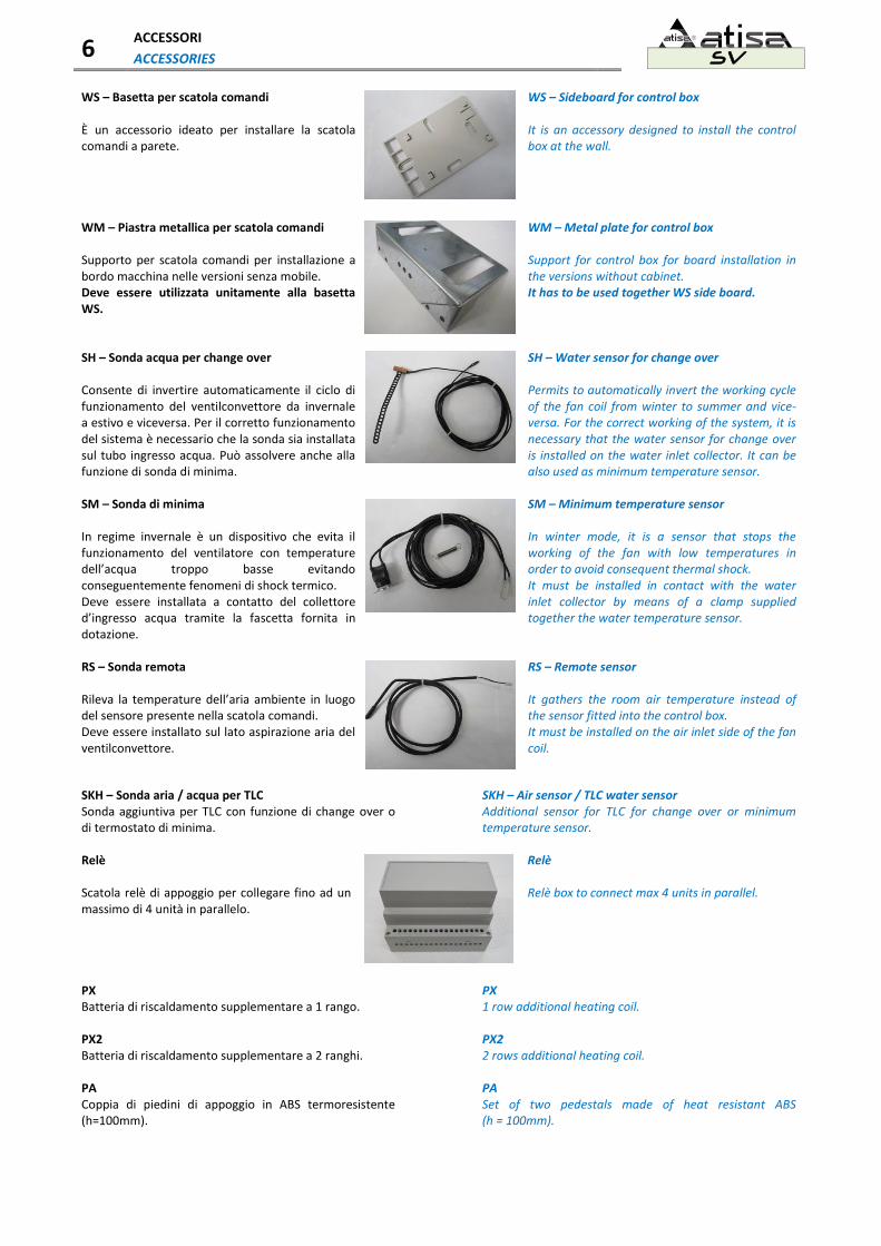
WS – Basetta per scatola comandi WS – Sideboard for control box È un accessorio ideato per installare la scatola comandi a parete.
It is an accessory designed to install the control box at the wall.
WM – Piastra metallica per scatola comandi WM – Metal plate for control box Supporto per scatola comandi per installazione a bordo macchina nelle versioni senza mobile. Deve essere utilizzata unitamente alla basetta WS.
Support for control box for board installation in the versions without cabinet. It has to be used together WS side board.
SH – Sonda acqua per change over SH – Water sensor for change over Consente di invertire automaticamente il ciclo di funzionamento del ventilconvettore da invernale a estivo e viceversa. Per il corretto funzionamento del sistema è necessario che la sonda sia installata sul tubo ingresso acqua. Può assolvere anche alla funzione di sonda di minima.
Permits to automatically invert the working cycle of the fan coil from winter to summer and vice-versa. For the correct working of the system, it is necessary that the water sensor for change over is installed on the water inlet collector. It can be also used as minimum temperature sensor.
SM – Sonda di minima SM – Minimum temperature sensor In regime invernale è un dispositivo che evita il funzionamento del ventilatore con temperature dell’acqua troppo basse evitando conseguentemente fenomeni di shock termico. Deve essere installata a contatto del collettore d’ingresso acqua tramite la fascetta fornita in dotazione.
In winter mode, it is a sensor that stops the working of the fan with low temperatures in order to avoid consequent thermal shock. It must be installed in contact with the water inlet collector by means of a clamp supplied together the water temperature sensor.
RS – Sonda remota RS – Remote sensor Rileva la temperature dell’aria ambiente in luogo del sensore presente nella scatola comandi. Deve essere installato sul lato aspirazione aria del ventilconvettore.
It gathers the room air temperature instead of the sensor fitted into the control box. It must be installed on the air inlet side of the fan coil.
SKH – Sonda aria / acqua per TLC SKH – Air sensor / TLC water sensor Sonda aggiuntiva per TLC con funzione di change over o di termostato di minima.
Additional sensor for TLC for change over or minimum temperature sensor.
Relè Relè Scatola relè di appoggio per collegare fino ad un massimo di 4 unità in parallelo.
Relè box to connect max 4 units in parallel.
PX PX Batteria di riscaldamento supplementare a 1 rango.
1 row additional heating coil.
PX2 PX2 Batteria di riscaldamento supplementare a 2 ranghi. 2 rows additional heating coil.
PA PA Coppia di piedini di appoggio in ABS termoresistente (h=100mm).
Set of two pedestals made of heat resistant ABS (h = 100mm).
6 ACCESSORI
ACCESSORIES SV
BS – BSP (solo per modelli orizzontali) BS – BSP (horizontal models only) Bacinella secondaria in materiale plastico termoresistente, per raccolta condensa sul lato collettori (per modelli verticali).
Secondary drain pan made of plastic material for condensate discharge on collector’s side (vertical models only).
RE RE Resistenza elettrica ad elementi in alluminio alettati protetti da contatti accidentali tramite griglia metallica. Scatola di protezione IP54 contenente un relè di potenza da 16A e morsetti di appoggio per alimentazione e comando. La resistenza è equipaggiata con due termostati di sicurezza a taratura differenziata, uno a riarmo automatico ed uno a riarmo manuale, fissati a diretto contatto con la parte elettrica. Per rese termiche vedere “Listino Prezzi”.
Electric heater having aluminium elements protected from casual contacts by means of metallic grille. Protection box IP54 containing 16A power relay and terminals for electrical supply and control. The electric heater is equipped by two different set points safety thermostats, one for automatic reset and the other one for manual reset, fixed at direct contact with the finned area. For capacities see “Price List”.
PC PC Pannello in lamiera preverniciata, per chiusura posteriore.
Rear prepainted covering panel.
CA CA Flangia in lamiera zincata, per canalizzazione di mandata. Galvanized sheet flange for duct connection.
SC SC Pompa di scarico condensa con controllo di livello a 3 posizioni.
Condensate discharge pump with 3 position level control.
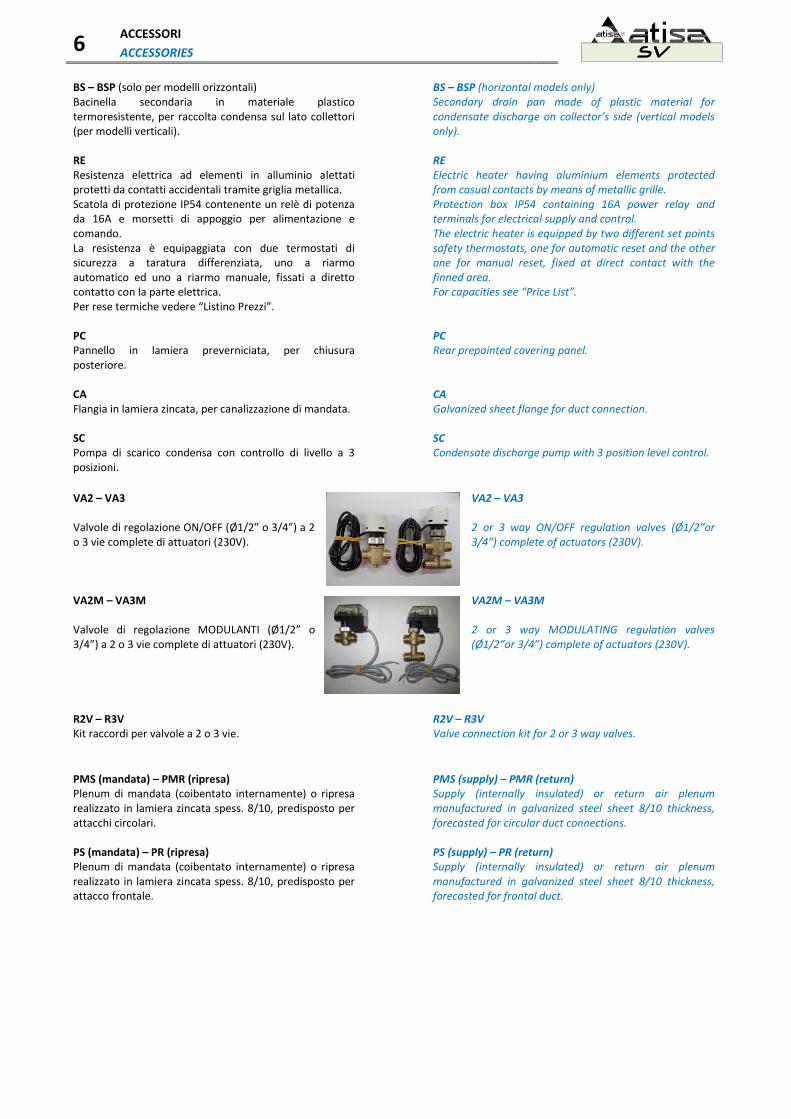
VA2 – VA3 VA2 – VA3 Valvole di regolazione ON/OFF (Ø1/2” o 3/4”) a 2 o 3 vie complete di attuatori (230V).
2 or 3 way ON/OFF regulation valves (Ø1/2”or 3/4”) complete of actuators (230V).
VA2M – VA3M VA2M – VA3M Valvole di regolazione MODULANTI (Ø1/2” o 3/4”) a 2 o 3 vie complete di attuatori (230V).
2 or 3 way MODULATING regulation valves (Ø1/2”or 3/4”) complete of actuators (230V).
R2V – R3V R2V – R3V Kit raccordi per valvole a 2 o 3 vie.
Valve connection kit for 2 or 3 way valves.
PMS (mandata) – PMR (ripresa) PMS (supply) – PMR (return) Plenum di mandata (coibentato internamente) o ripresa realizzato in lamiera zincata spess. 8/10, predisposto per attacchi circolari.
Supply (internally insulated) or return air plenum manufactured in galvanized steel sheet 8/10 thickness, forecasted for circular duct connections.
PS (mandata) – PR (ripresa) PS (supply) – PR (return) Plenum di mandata (coibentato internamente) o ripresa realizzato in lamiera zincata spess. 8/10, predisposto per attacco frontale.
Supply (internally insulated) or return air plenum manufactured in galvanized steel sheet 8/10 thickness, forecasted for frontal duct.