Embed Size (px)
Citation preview

E-PAC AmplifierHardware manual (1.2 EN)

Symbols on the equipment
Please refer to the information in the operatingmanual.
WARNING! Dangerous voltage!
General Information
E-PAC AmplifierHardware manual
Version 1.2 EN, 02/2013, D2014.E.01
Copyright © 2013 by d&b audiotechnik GmbH; all rights reserved.
Keep this manual with the product or in a safe place sothat it is available for future reference.
In the case of reselling this product handout this manual to the newcustomer.
If you supply d&b products, please draw the attention of yourcustomers to this manual. Enclose the relevant manuals with the systems.If you require additional manuals for this purpose, you can order themfrom d&b.
d&b audiotechnik GmbHEugen-Adolff-Strasse 134, D-71522 Backnang, GermanyTelephone +49-7191-9669-0, Fax +49-7191-95 00 00E-mail: [email protected], Internet: www.dbaudio.com

Contents
1. Safety precautions...........................................................4
1.1. Information regarding use of the E-PAC Amplifier.........................4
1.2. Service/Maintenance...............................................................................4
2. Introduction......................................................................5
2.1. Intended use...............................................................................................5
2.2. Scope of supply.........................................................................................5
3. E-PAC Amplifier................................................................6
3.1. E-PAC based systems...............................................................................6
3.2. Block diagram............................................................................................6
3.3. Power supply..............................................................................................7
3.4. Protective circuits.......................................................................................7
3.5. Cooling.........................................................................................................8
3.6. E-PAC power amplifiers..........................................................................8
3.7. Digital signal processing..........................................................................8
3.8. Remote control...........................................................................................8
4. Controls and indicators....................................................9
4.1. Controls........................................................................................................94.1.1. Power switch [1].............................................................................94.1.2. MUTE switch (green LED) [2]......................................................94.1.3. LEVEL/PUSH MENU (Digital rotary encoder) [3]...............10
4.2. Indicators...................................................................................................114.2.1. LC Display [4]...............................................................................114.2.2. ISP LED - Input Signal Present (green) [5]............................114.2.3. GR LED - Gain Reduction (yellow) [6]...................................114.2.4. OVL LED - Overload (red) [7].................................................11
5. Connections....................................................................12
5.1. Mains Connector [8]..............................................................................12
5.2. Fuse protection [9]..................................................................................12
5.3. Signal inputs and link outputs.............................................................135.3.1. INPUT [12] and LINK [13].........................................................135.3.2. MIX IN [14]...................................................................................13
5.4. Loudspeaker output connectors - [15]..............................................13
5.5. REMOTE interface [14].........................................................................145.5.1. REMOTE [10]...............................................................................14
5.6. SERVICE [11]............................................................................................14
6. Installation and operation............................................15
6.1. Installation.................................................................................................156.1.1. E-PAC Rack mount kits..............................................................16
6.2. Dimensions................................................................................................17
6.3. Operation.................................................................................................186.3.1. Electromagnetic compliance....................................................186.3.2. Power consumption and power loss......................................18
7. Technical specifications..................................................20
8. Manufacturers declarations..........................................22
8.1. EU declaration of conformity (CE symbol).......................................22
8.2. WEEE declaration (Disposal)...............................................................22
E-PAC Amplifier, Hardware manual (1.2 EN) Contents - 1

1. Safety precautions
1.1. Information regarding use of the E-PAC Amplifier
The E-PAC is a protective class 1 unit. Make sure that the earth (ground)contact is attached when the unit is in operation. A missing earth(ground) contact may lead to dangerous voltages in the housing andcontrols and my lead to electric shock.
Before connecting the device to mains voltage, check that the mainsvoltage and frequency corresponds to the specifications on theconfiguration sticker on the rear of the unit.
The amplifier's output pins can carry dangerous voltages. Only useisolated loudspeaker cables with correctly mounted connectors.Otherwise there is a potential risk of electric shock.
Never connect an amplifier output pin to any other in or outputconnector pin or earth (ground). This might lead to electric shock ordamage the unit.
Lay all cables connected to the unit in a way that they cannot becrushed by vehicles or other equipment.
Do not not put any kind of objects filled with liquids (e.g. Drinks) onto theunit.
Avoid ambient conditions with:
• excessive humidity or steam.
• excessive dust or other small particles.
• oil steam or splashes.
• excessive heat or direct sunlight.
Do not block vents at the front or air intake at the rear and providesufficient cooling.
1.2. Service/Maintenance
Do not open the unit. No user serviceable parts inside.
In the case of any damage to the unit under no circumstances connectand operate the unit.
For any damage to the power cord, the power cord must not be usedand must be disposed of from any further use.
Refer servicing only to qualified service personnel authorized byd&b audiotechnik. In particular in the case of:
• mains power cord, socket or plug has been damaged.
• objects or liquids have entered the unit.
• the unit is not operating normally.
• the unit was dropped or the housing is damaged.
E-PAC Amplifier, Hardware manual (1.2 EN) Page 4 of 24

2. Introduction
This manual describes the facilities and functions of the hardware of thed&b E-PAC Power amplifier controller.
2.1. Intended use
The E-PAC amplifier is a one channel power amplifier and controllerunit. It is designed for use with the d&b fullrange loudspeakers (passivesystems) and subwoofer systems.
A linear mode is available allowing the E-PAC to be used as a linearpower amplifier.
2.2. Scope of supply
Initial inspection
Before starting up please verify the shipment for completeness:
Qty. d&b Code Description
1 Z2510 E-PAC Amplifier
1 K0025.030 Power cord
1 D2014.E.01 E-PAC Amplifier, Hardware manual
1 D2015.E.01 E-PAC Amplifier, Software manual
For any sign of obvious damage to the unit duringshipment under no circumstance connect and operatethe unit!
E-PAC Amplifier, Hardware manual (1.2 EN) Page 5 of 24
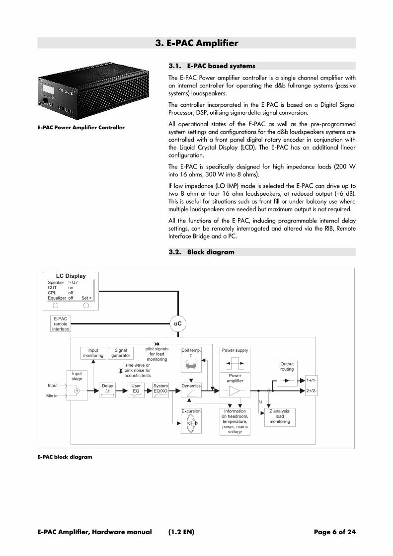
3. E-PAC Amplifier
E-PAC Power Amplifier Controller
3.1. E-PAC based systems
The E-PAC Power amplifier controller is a single channel amplifier withan internal controller for operating the d&b fullrange systems (passivesystems) loudspeakers.
The controller incorporated in the E-PAC is based on a Digital SignalProcessor, DSP, utilising sigma-delta signal conversion.
All operational states of the E-PAC as well as the pre-programmedsystem settings and configurations for the d&b loudspeakers systems arecontrolled with a front panel digital rotary encoder in conjunction withthe Liquid Crystal Display (LCD). The E-PAC has an additional linearconfiguration.
The E-PAC is specifically designed for high impedance loads (200 Winto 16 ohms, 300 W into 8 ohms).
If low impedance (LO IMP) mode is selected the E-PAC can drive up totwo 8 ohm or four 16 ohm loudspeakers, at reduced output (–6 dB).This is useful for situations such as front fill or under balcony use wheremultiple loudspeakers are needed but maximum output is not required.
All the functions of the E-PAC, including programmable internal delaysettings, can be remotely interrogated and altered via the RIB, RemoteInterface Bridge and a PC.
3.2. Block diagram
Power
amplifier
Input
stage
Input
Mix in
Signal
generator
sine wave or
pink noise for
acoustic tests
Input
monitoring
User
EQ
Delay
t
Dynamics
Coil temp.
t°
Power supply
Information
on headroom,
temperature,
power, mains
voltage
Excursion Z analysis:
load
monitoring
1+/1-
2+/2-
U I
System
EQ/XO
pilot signals
for load
monitoring
LC DisplaySpeaker
CUT
CPL
Equalizer
> Q7
on
off
off Set >
E-PAC
remote
interface
Output
routing
+
uC
E-PAC block diagram
E-PAC Amplifier, Hardware manual (1.2 EN) Page 6 of 24

3.3. Power supply
The switched mode mains power supply permits worldwide applicationwithout the need for mains voltage switching or conversion. Specialregulation of the power supply unit additionally guarantees constantoutput power with fluctuating mains voltage, leading to a substantiallyhigher dynamic stability than a conventional power supply unit of thesame performance. This benefits the reproduction of music or speechwith a wide dynamic range.
Active Power Factor Correction (PFC) is characterised by the currentdrawn being represented by an almost sinusoidal waveform, resulting inlower loss, in contrast to the pulse shaped current characteristic ofpower supplies without PFC. This is an advantage where long mainspower supply cables are used.
The mains voltage and power consumption are recorded by the powersupply and can be viewed on the LCD display.
3.4. Protective circuits
The E-PAC contains many integrated protective functions:
If over temperature occurs, the device switches to mute. After it hascooled down, the output stage resets automatically.
The output current limiter (SOA watchdog) prevents damage to theoutput stage that could occur from a short-circuit or incorrect cabling,while passing the short current peaks drawn by a complex load like aloudspeaker.
The mains power connection is protected by a fuse.
A mains inrush current limiter provides a 'soft start' and enables severalE-PACs to be powered up at the same time without over-loading themains power supply.
The maximum current draw during the power up phase is dependant onthe mains voltage, however nominal values are 2 A (peak) at 230 Vand 4 A (peak) at 115 V.
The nominal operating range of the E-PAC is between 85 V and 265 V(100 V –15% /230 V +15 %). Where voltages outside of this rangeare present, a self-resetting protective circuit responds quickly to isolatethe internal amplifier power supply leaving only a supervisory circuit tomonitor the mains voltage. The display will clearly indicate the fault andvoltage value, the display illumination switching off after 10 seconds.
The supervision circuit will operate up to 400 V; this allows the E-PAC to survive connection across two phases of a three phase supply.
To prevent the E-PAC from cycling on and off with fluctuating mainspower supply voltages, the switching thresholds are delayed dependanton the condition breached. These voltage thresholds and correspondingtransition delay times are listed in the table below.
Mains voltageVRMS
Condition
from ⇒⇒⇒⇒ to
Delay
276 V ON OFF 1 msec.
267 V OFF ON 2 sec.
83 V OFF ON 2 sec.
77 V ON OFF 20 msec.
E-PAC Amplifier, Hardware manual (1.2 EN) Page 7 of 24

To ensure a fast response to irregular mains conditions, the mainsvoltage is registered in the E-PAC as an instantaneous peak value, theswitching thresholds correlated to that peak value. Peak values areconverted to rms values for display purposes. However a real-world ACmains power supply is not typically represented by a perfect sinewave,therefore, the peak-to-rms conversion is based on a typical sinewavewith a flat top at 96% of the amplitude of an ideal sinewave. As aconsequence, the displayed voltage and the actual switching thresholdswill depend on the shape of the mains voltage or the quality of themains power supply, respectively.
3.5. Cooling
The aluminium enclosure acts as a heat sink for the E-PAC poweramplifier; it is therefore convection-cooled. To prolong the life ofcomponents inside the E-PAC, a small fan located at the front of the E-PAC intakes cooling air through an opening in the rear panel. The quietrunning fan is activated at two temperature thresholds. One at 30°C(86°F) and a second, whereby the fan will draw air at a faster flow rate,at above 45°C (113°F).
WARNING! Do not touch the heat sink. During operation the cooling fins of the heatsink on the enclosure of the E-PAC can reach temperatures of 80°C(176°F). The front and rear panels do not form part of the heat sink andcan be touched at any time.
3.6. E-PAC power amplifiers
The single channel power amplifier of the E-PAC maintains high linearitythroughout it’s operational range even into adverse loads. With fastresponse to, and recovery from overload conditions, stability andaccurate performance is guaranteed. A two stage power supply keepsthe losses through heat emission low. To maintain sound quality, a limitercircuit prevents the amplifier from continuously reaching its maximumoutput voltage, known as clipping.
The E-PAC can deliver 200 W continuous sine wave output power intoa 16 ohm load or 300 W into an 8 ohm load. Selecting low impedancemode enables the E-PAC to deliver an output power of 150 W into4 ohms. These values apply to continuous operation for a minimum of30 minutes at a maximum ambient temperature of 24°C (75°F).
An E-PAC will normally be operated with speech or music programme,complex signals where the average power requirement is below peakpower. The E-PAC will continue to operate indefinitely even where thesignal has a very low peak to RMS ratio, provided the device is installedto enable the heat generated to be adequately dissipated.
3.7. Digital signal processing
The digital signal processing provides loudspeaker specific set ups thatare selected using the front panel controls. These set ups include allloudspeaker equalization and protection functions. The basic latency ofthe E-PAC is 1 msec. including conversion (AD/DA conversion).
3.8. Remote control
The REMOTE sockets can be used with either the dbCAN (CAN-Bus)interface or with a serial interface to the d&b Remote Interface Bridge(RIB) to integrate the E-PAC into a control and monitoring system.
E-PAC Amplifier, Hardware manual (1.2 EN) Page 8 of 24

4. Controls and indicators
OVLGRISP
LEVEL
PUSH MENU
MUTE
POWER 2
3
4
5
[4] [3] [2] [5][6][7] [1]
E-PAC Controls and indicators
4.1. Controls
4.1.1. Power switch [1]
[1]
Mains power switch
The on/off switch is located on the rear panel and isolates the mainspower supply to the E-PAC. The MUTE/POWER switch [2] on the frontpanel has the functions ON/MUTE/STANDBY and does not isolate theE-PAC from the mains power supply.
off: the E-PAC is isolated from the mains power supply except theovervoltage protection circuit. The power consumption is very low (2 Wtypical).
on: the E-PAC is switched on. Via remote or the MUTE control the E-PAC can be switched to standby mode. To indicate standby mode thedisplay remains active.
4.1.2. MUTE switch (green LED) [2]
OVLGRISP
LEVEL
PUSH MENU
MUTE
POWER 2
3
4
5
[3] [2]
Controls
When the rear panel mains power switch is set to the on position, thecombined MUTE/POWER switch can be used to place the E-PAC eitherin mute or standby mode. The switch incorporates a green LED indicatorwhich indicates three different states - ON, MUTE and STANDBY.
- LED on » ON (unmuted): the E-PAC is powered on and readyfor use. A brief press of the MUTE/POWER switch will mute the E-PAC, a longer press places the E-PAC in standby mode.
- LED regular flashing (1:1 duty cycle): » MUTE: the E-PAC ismuted. In the mute state, the input signal is muted but the power ampis still powered and connected to the speaker output. The E-PAC isunmuted by briefly pressing the MUTE/POWER switch. A longerpress of the MUTE/POWER switch will place the E-PAC in standbymode.
- Regular short flashes (1:8 duty cycle): » STANDBY: in standby mode the loudspeaker output is electronically isolated andthe E-PAC idles, drawing minimal mains power. Only the mostessential functions are provided. Display and network remainfunctional, the display illumination is switched off after 10 seconds.Pressing the MUTE/POWER switch powers on the E-PAC ready foruse. The E-PAC may also be powered back on by remote controlfrom standby mode.
E-PAC Amplifier, Hardware manual (1.2 EN) Page 9 of 24
IMPORTANT! When the E-PAC is set to STANDBY (or the mains power is turned off)the movement of the loudspeaker cones in the cabinets connected is nolonger damped by the power amplifier output. This removal of thedamping makes them susceptible to excitation by other loudspeakers inthe surroundings. Audible resonances may occur, and even absorptionof low frequency sound energy as the undamped loudspeakers act likea 'bass trap'. To permanently mute single subwoofer cabinets it istherefore preferable to use the MUTE function instead of STANDBY.The STANDBY mode, however, can be of advantage with mid-highsystems, because it will remove any residual noise from the system.
The MUTE/POWER switch is a 'soft' switch which doesn’t electricallyisolate the E-PAC from the mains supply. The E-PAC circuitry can beelectrically isolated from the mains supply by switching the rear panelmains power switch to its off position.
The setting of the MUTE/POWER switch is stored in the E-PAC when themains power is turned off or disconnected. After reconnecting the E-PAC it will revert to the same status as before disconnection.
4.1.3. LEVEL/PUSH MENU (Digital rotary encoder) [3]
Operation, configuration and status viewing of the E-PAC are allaccessed via the front panel digital rotary encoder; LEVEL/PUSHMENU. In the main menu the encoder acts as a level control. Pushing orturning the encoder gives access to different menu levels or enablesconfigurations or values to be entered.
Brief press: access to the menu level.
A detailed description of the menu structure and access is given in theE-PAC Software manual, which is also provided with the E-PAC.
E-PAC Amplifier, Hardware manual (1.2 EN) Page 10 of 24

4.2. Indicators
4.2.1. LC Display [4]
OVLGRISP
[4] [5][6][7]
E-PAC Indicators in detail
Serves as a user interface and display for all configuration settings andstatus information.
The display is illuminated and can be set to "on/off/timeout 10s."
A detailed description of the menu structure and access is given in theE-PAC Software manual, which is also provided with the E-PAC.
4.2.2. ISP LED - Input Signal Present (green) [5]
Illuminates when the E-PAC input signal exceeds –30 dBu. The ISPindication is unaffected by the setting of the level control and the MUTEfunction but will not operate in STANDBY mode.
4.2.3. GR LED - Gain Reduction (yellow) [6]
Illuminates depending on the input signal: the E-PAC limitercircuit reduces gain by more than 3 dB. This state is not critical butshows that the system has reached its limits.
4.2.4. OVL LED - Overload (red) [7]
Illuminates depending on the input signal:
- While the green ISP-LED is lit » Overload: either the inputsignal level is too high or the E-PAC is trying to deliver too high anoutput current. If in doubt of the reason reduce the input gain at theE-PAC level control. If the error message disappears, the outputcurrent has been too high (load impedance too low caused by tomany loudspeakers connected to the E-PAC output, or a defectivecable or connector). If the condition does not change, the input signalto the E-PAC is too high (greater than +23.5 dBu).An overload could also be caused by accumulate the source inputINPUT+MIX IN or by high gain settings (boosts) in the single EQbands, while the input signal is lower than +23.5 dBu.
- Flashes (1:1 mark space) » Error: an error message will bedisplayed.
E-PAC Amplifier, Hardware manual (1.2 EN) Page 11 of 24

5. Connections
[8][9] [15][14][11][12][10][13]
5.1. Mains Connector [8]
IMPORTANT! Before connecting the device to mains voltage, check that the mainsvoltage and frequency corresponds to the specifications on theconfiguration sticker on the rear of the E-PAC.
[8][9]
E-PAC Mains power
A 3-pin IEC socket with an integrated fuse holder is provided forconnecting the E-PAC to the mains power supply.
A suitable power cable is supplied.
5.2. Fuse protection [9]
A replaceable 20 mm fuse located above the 3-pin IEC socket isintegrated in the socket (5 A Time Lag (T)). This is connected in series tothe power supply and fails if the current drain is exceeded. There is aspare fuse in the fuse holder.
WARNING! If the fuse has failed disconnect the E-PAC from the mainssupply before replacement.
Only use a fuse of the correct type and nominal currentvalue.
Before restoring power to the E-PAC all cabling should be checked forfaults. If in any doubt disconnect all signal and loudspeaker connections.
E-PAC Amplifier, Hardware manual (1.2 EN) Page 12 of 24

5.3. Signal inputs and link outputs
[15] [14] [12] [13]
E-PAC I/O Connectors
All signal input and output connections are located on the rear panel.These include analogue signal inputs (INPUT/MIX IN), link output (LINK)and a NL4 loudspeaker output (SPEAKER OUT).
5.3.1. INPUT [12] and LINK [13]
Pin assignment E-PAC signal inputs
The E-PAC signal input connector is a 3 pin female XLR.
Below and wired in parallel is a 3 pin male XLR input link connector usedto feed the input signal on to the next device in the system signal chain.
5.3.2. MIX IN [14]
A 3 pin female XLR connector provides a MIX IN input. A second signalfed to this input is summed to the main INPUT. If Left and Rightcomponents of a stereo source are fed to the main INPUT and MIX INconnections then a mono sum signal is derived from the speaker output.Please note that the resultant output is 3 dB higher.
The output on the INPUT LINK connector is derived from the signal fedto the INPUT connector. An additional signal fed to the MIX INconnector will not appear at the INPUT LINK output.
5.4. Loudspeaker output connectors - [15]
The E-PAC is fitted with a single Speakon-NL4 speaker outputconnector. With configuration settings which transmit full-range signal(e.g. E3 or LINEAR) all four pins on the Speakon connector are driven,pins 1+ and 2+ carry positive signal, 1– and 2– carry negative signal.With SUB configurations selected pin 1+ is disconnected automatically.This prevents mid-high cabinets from accidental damage by subwoofersignal.
E-PAC Amplifier, Hardware manual (1.2 EN) Page 13 of 24

5.5. REMOTE interface [14]
[11] [10]
E-PAC Remote interfaces
5.5.1. REMOTE [10]
1......8 1......8 Pin 1 n.c.Pin 2 n.c.Pin 3 n.c.Pin 4 CAN_HPin 5 CAN_LPin 6 n.c.Pin 7 RIB Data +Pin 8 RIB Data -Shield CAN Ground1 8. . . . . .
Pin assignment for remote control (RJ45)
The E-PAC is fitted with a two-wire serial remote control interface, (2 xRJ 45) carrying both the RIB and CAN-Bus signals. All pins of bothconnectors are wired in parallel allowing either to be used as the inputor output. Where remote control networking conforms to a 'Bus or Ringtopology' one connector is used for the incoming signal and the secondconnector allows for direct connection to another device or forterminating in case of a CAN-Bus network. The interface connections forthe RIB (pin 7/8) are opto-coupled, while the connections for the CAN-Bus (pin 4/5) are hard wired to common ground (protective earth).
Pin Signal Remark
1 -
2 -
3 -
4 CAN_H "CAN high bus" signal (active high)
5 CAN_L "CAN low bus" signal (active low)
6 -
7 RIB Data
8 RIB Data
Enclosure GND CAN Ground
RJ45 pin assignment on d&b devices
The "CAN Ground" is routed via the cable shielding. Within the CAN-Bus network, shielded cables and shielded RJ 45 connectors must beused while the cable shielding must be connected to both sides of theRJ 45 connector.
A detailed description of remote control via dbCAN (CAN-Bus) is givenin the technical information TI 312 (d&b code D5312.E.).
5.6. SERVICE [11]
The D-SUB-9 SERVICE interface (RS 232 female) allows operatingsoftware and loudspeaker configuration updates to be loaded into theunit.
IMPORTANT! To connect the computer to the SERVICE connector a standard RS-232connection cable (D-SUB-9 serial cable female/male - 1:1) must beused (serial extension cable).
Pin Signal Remark
2 RxD
3 TxD
4 DTR
5 GND Signal
7 RTS
E-PAC Amplifier, Hardware manual (1.2 EN) Page 14 of 24

6. Installation and operation
6.1. Installation
A single E-PAC may be installed in a 9.5" equipment rack or a standard19“ equipment rack or flightcase. A single E-PAC or a pair side-by-sidemay be installed in a standard 19" equipment rack or flightcase. E-PACsrequire two rack units and, including connectors, a minimum rack depthof 40 cm (16"), mounting ear to rack rear panel.
E-PAC with solo rack mount kit(Z2501)
E-PACs with dual rack mount kit (Z2502) E-PACs with 9.5” rack mount kit(Z2503)
IMPORTANT! It is recommended that additional support be provided within the rackby using the rear mounted rack ears [3]. This is particularly important ifE-PACs are being racked for road use.
The E-PAC enclosure can get hot during operation, therefore allow agap of at least 2 cm (3/4") between an E-PAC and the rack top/bottompanels, or other equipment above or below (see figure on the left). Thisis not necessary between adjacent E-PACs.
When installing E-PACs always allow sufficient free air flow around theenclosure and never block or cover the rear panel air intake vent or thefront panel air outlet vent. If E-PACs are to be installed in sealedequipment racks, then additional fan modules will be needed. The E-PAC air intake is on the rear panel; therefore external fans shouldsupply air to the rear side of the rack.
2 cm / 0.8" Vent
2 cm / 0.8" Vent
OVLGRISP
E-PAC
LEVEL
PUSH MENU
MUTE
POWER
OVLGRISP
E-PAC
LEVEL
PUSH MENU
MUTE
POWER
OVLGRISP
E-PAC
LEVEL
PUSH MENU
MUTE
POWER
OVLGRISP
E-PAC
LEVEL
PUSH MENU
MUTE
POWER
cooling air100 mm [4"]free space338 mm
[13.3"]
supporton bothsides
20 mm [3/4"] vent below
20 mm [3/4"] vent above
Convection type cooling.Enclosure can get
hot during operation.
CAUTION !
E-PAC Rack mounting / Installation
E-PAC Amplifier, Hardware manual (1.2 EN) Page 15 of 24

6.1.1. E-PAC Rack mount kits
[1]
[2][3] [4]
[5]
[K]
E-PAC Rack mounting kit items
The solo rack mount kit Z2501 allows one E-PAC to be mounted eitherto the left or the right hand side in a standard 19" equipment rack orflightcase.
The solo rack mount kit (Z2501) includes the following parts:
- 4 x mounting rails [1]
- 1 x front rack mounting bracket [2]
- 1 x rear mounted rack ear [3]
- 1 x front blanking panel [5]
- 6 x Allen screws [S]
- 1 x Allen key [K]
The dual rack mount kit Z2502 allows two EPACs side-by-side to bemounted in a standard 19" rack or flightcase.
The dual rack mount kit (Z2502) includes the following parts:
- 8 x mounting rails [1]
- 2 x front rack mounting brackets [2]
- 2 x rear mounted rack ears [3]
- 2 x connector brackets [4]
- 16 x Allen screws [S],
- 1 x Allen key [K]
The solo rack mount kit Z2503 allows one E-PAC to be mounted in a9.5“ equipment rack or flightcase.
The solo rack mount kit (Z2503) includes the following parts:
4 x mounting rails [1]
2 x front rack mounting brackets [2]
2 x rear mounted rack ears [3]
8 x Allen screws [S]
1 x Allen key [K]
Assembly
[1]
[2]
[S]
The mounting rails [1] are inserted into channels located in the sidewalls of the E-PAC aluminum enclosure. The different fittings[2,3,4 and 5] are attached using countersunk Allen (Hex) screws [S]using the supplied Allen key [K].
E-PAC Amplifier, Hardware manual (1.2 EN) Page 16 of 24

6.2. Dimensions
OVLGRISP
E-PAC
LEVEL
PUSH MENU
MUTE
POWER
REMOTE
Made in Germany
MIX IN INPUTSPEAKER OUT INPUT LINK
SERVICE
www.dbaudio.com
CAUTION
R ISK O F ELECT RIC SHOCK DO NOT OPEN
E-PAC
Z2500000101236
E-PAC front view E-PAC rear view
483 [19.00"]
465 [18.30"]
76 [3.0
0"]
OVLGRISP
E-PAC
LEVEL
PUSH MENU
MUTE
POWER
OVLGRISP
E-PAC
LEVEL
PUSH MENU
MUTE
POWER
190 [7.48"] 336 [13.23"]
88 [3.4
6"]
OVLGRISP
E-PAC
LEVEL
PUSH MENU
MUTE
POWER
88 [3.4
6"]
338 [13.31"]
357 [14.06"]240 [9.45"]
222 [8.74"]
76 [3.0
0"]
OVLGRISP
E-PAC
LEVEL
PUSH MENU
MUTE
POWER
E-PAC enclosure dimensions in mm [inch]
E-PAC Amplifier, Hardware manual (1.2 EN) Page 17 of 24

6.3. Operation
6.3.1. Electromagnetic compliance
The device complies with the electromagnetic compatibility requirementsof EN 55103 (product family standard for audio, video, audio-visualand entertainment lighting control apparatus for professional use) forthe environments E1 (residential), E2 (business and commercial), E3(outdoor use in urban areas) and E4 (outdoor use in rural areas).
Acoustic interference and malfunctions may occur if the unit is operatedin the immediate vicinity of high-frequency transmitters (e.g. wirelessmicrophones, mobile phones, etc.). Damage to the mainframe is unlikely,but cannot be excluded.
6.3.2. Power consumption and power loss
The power required from the mains supply and the waste heatproduced by the amplifiers power loss are variable figures dependingon the load impedance and the signal levels and characteristics (e.g.speech, music).
In practice, the theoretical peak power consumption of a system willonly be sustained for a short period of time. Basing mains current andair conditioning plant requirements on the peak power consumption ofthe sound system would result in a generously over-specifiedinstallation. The key factor in power consumption calculations is the crestfactor of the signal - the ratio of peak to sustainable RMS voltage of thesignal.
Power input and electrical (⇒ thermal) power loss for different signaland load conditions can be derived from the graphs shown below.
196
80
50
300
120
78
--
159
60
34
102
86
47
156
125
85
123
118
79
1.4 2.8 3.5 1.4 2.8 3.5 1.4 2.8 3.50
100
200
300
400
500
Crestfactor
4 ohms (LO IMP)8 ohms16 ohms
pow
er
[W]
loss
output
Maximum output power and power loss of E-PAC for different signalcharacteristics (Crest factors) at full level.
E-PAC Amplifier, Hardware manual (1.2 EN) Page 18 of 24

5 10 100 20030
100
400
consumption
loss
pow
er
[W]
average output power [W]5 10 100 200
30
100
400
consumption
loss
pow
er
[W]
average output power [W]
Power consumption and loss of E-PAC as a factor of outputpower (WRMS into 8 ohms) with pink noise signal
Average power consumption and loss of E-PAC as a factor ofoutput power (WRMS into 16 ohms) with pink noise signal
E-PAC Amplifier, Hardware manual (1.2 EN) Page 19 of 24

7. Technical specifications
Displays
ISP...........................................................................Input Signal Present indicator (green)GR..................................................................................Gain Reduction indicator (yellow)OVL...................................................................................Overload/Error indicator (red)MUTE/POWER.....................................................On/Mute/Standby indicator (green)Liquid Crystal Display (LCD)......................................................................120 x 32 Pixel
Controls
I/O...........................................................................................................Main power switchMUTE/POWER.........................................................................On/Mute/Standby switchLEVEL/PUSH MENU......................................................................Digital rotary encoder
Access to all functions including:
Level control.....................................................–57.5 dB ... +6 dB with 0.5 dB detentsConfigurations............................................................................................Filter_1/Filter_24 band equalizer.............................................................................Optional Peak/NotchDelay setting...................................................1.0 ... 220 msec. with 0.1 msec. detentsSystem configurations................................passive Fullrange systems and Subwoofe...............................................................................................................................linear modeImpedance measurement (Z)................................................................... 0 to 255 ohmsProtection..................................................Operator input inhibit/password protectionRemote control............................................................................................. RIB(TI212)/RIBDevice name..................................................................................15 alphanumeric digitsDisplay illumination..........................................................................Off/On/Timeout 10sFrequency generator....alternative sine wave, 10 Hz ... 20 kHz with 1 Hz detents.................................................................................................................................Pink Noise.............................................................................–57.5 dB ... +6 dB with 0.5 dB detentsBuzzer.....................................................................Acoustical signal for Error Messages
Impedance Monitoring according to EN 60849/IEC 60849'Sound Systems for Emergency Purposes'
Input monitoring...............................................................Detecting external Pilot Signal
Load monitoring.............................................................................Impedance monitoring
........................................................program and/or Pilot Signal at 10 Hz and 20 kHz
System check..............................................................Manual impedance measurement
...........................................................................to calibrate before, and verify after use
Connectors
INPUT....................................................................................3 pin XLR (female), balancedINPUT LINK................................................................3 pin XLR (male) parallel to INPUTMIX IN .................................................................................3 pin XLR (female) balancedSPEAKER OUT..................................................................................................................NL4Pin assignments full range speakers........................................................1+/1–, 2+/2–Pin assignments active subwoofers......................................................................2+ / 2–REMOTE..................................................................................................................2 x RJ 45SERVICE...........................................................................................................SUB-D9 (PS2)
Protection circuits
Mains inrush current limiter....................................2 A peak at 230 V, 4 A at 115 VOvervoltage protection..................................................................................up to 400 VSelf resetting overtemperature protection...............................................75°C /167°FOutput short and open circuit protection.............................................................±20 ASpeaker switch on delay..............................................................................approx 2 sec.
E-PAC Amplifier, Hardware manual (1.2 EN) Page 20 of 24

Data (linear-setting with subsonic filter)
Rated output power (THD + N < 0.1%)............................1 x 200 W into 16 ohms.........................................................................................................1 x 300 W into 8 ohmsLO IMP mode...............................................................................1 x 150 W into 4 ohmsFrequency response (–1 dB)...................................................................35 Hz – 22 kHzTHD+N (20 – 20k Hz)........................................................................................< 0.05 %IM (SMPTE)................................................................................................................< 0.1 %Slew rate...........................................................................................................50 V / msec.Damping factor (20 – 1k Hz into 16 ohms).........................................................> 160S/N ratio (unweighted, RMS, 0 dB)...................................................................> 94 dBrS/N ratio with MUTE (unweighted).................................................................> 104 dBrInput impedance....................................................................................................22 kohmsInput-CMR (100 Hz).............................................................................................< –60 dBInput-CMR (10 k Hz)............................................................................................< –40 dBMaximum input level..............................................................................................+21 dBu
(sum of INPUT and MIX IN)
Digital Signal Processing
Sampling rate..............................................................................................48 kHz / 24 bitBasic delay analog input incl. conversion (AD/DA)..........................................1 msec.Maximum delay setting..................................................220 msec. (75.68 m/246.1 ft)
Power consumption (typical values)
Standby ...........................................................................................................................2 W
ON, without signal.......................................................................................................27 W
ON, Standard signal* at 16 Ohms.........................................................................79 W
ON, Standard signal* at 8 Ohms.........................................................................114 W
............................................................Standard signal: Pink noise, 1/8 nominal power
Dimensions, weight and power supply
Height x width x depth .........................................................2 RU x 190 mm x 331mm...................................................................................................................2 RU x 7.5" x 13"Weight.........................................................................................................4.7 kg / 10.4 lbUniversal voltage range switched mode power supply with active power factorcorrection (PFC)Mains voltage rating..............................................................85 – 265 V / 50 – 60 HzMains fuse.....................................................................................................5A Time lag (T)
E-PAC Amplifier, Hardware manual (1.2 EN) Page 21 of 24

8. Manufacturers declarations
8.1. EU declaration of conformity (CE symbol)
This declaration applies to the E-PAC power amplifier controllermanufactured by d&b audiotechnik AG consisting of the amplifier unit.
- E-PAC Z2510 all versions
All production versions of type E-PAC starting from versionZ2510.000.01 are included, provided they correspond to the originaltechnical version and have not been subject to any later design orelectromechanical modifications.
We herewith declare that said products are in conformity with theprovisions of the following EC directives including all applicableamendments:
- 2006/95 Low Voltage
- 89/336 Electromagnetic Compatibility
The following standards have been applied:
DIN EN 60065:1998
DIN EN 55103-1:1996, classes E1 to E4
DIN EN 55103-2:1996, classes E1 to E4
8.2. WEEE declaration (Disposal)
Electrical and electronic equipment must be disposed of separately fromnormal waste at the end of its operational lifetime.
Please dispose of this product according to the respective nationalregulations or contractual agreements. If there are any further questionsconcerning the disposal of this product please contact d&b audiotechnik.
E-PAC Amplifier, Hardware manual (1.2 EN) Page 22 of 24


D2014.E
.01, 0
2/2
013 ©
d&
b a
udio
tech
nik
Gm
bH
d&b audiotechnik GmbH, Eugen-Adolff-Str. 134, D-71522 Backnang, Germany, Phone +49-7191-9669-0, Fax +49-7191-95 00 00_______