Embed Size (px)
Citation preview

E-R Model (II)
1

Roadmap of This Lecture
■ Weak Entity Sets ■ Extended E-R Features■ Reduction to Relation Schemas■ Database Design■ UML*
2
Weak Entity Sets
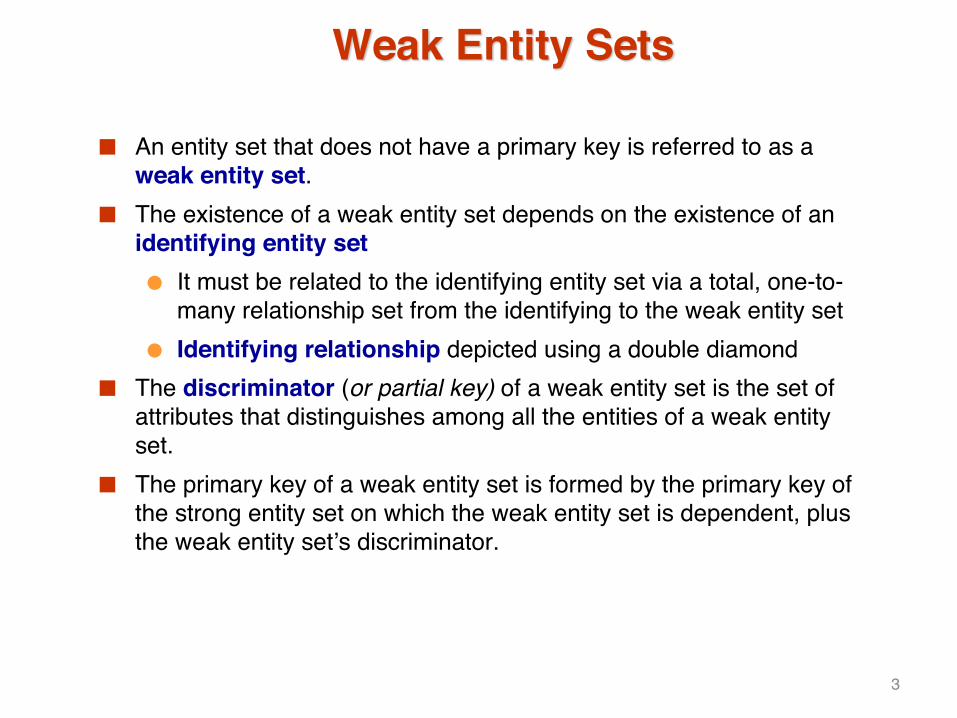
■ An entity set that does not have a primary key is referred to as a weak entity set.
■ The existence of a weak entity set depends on the existence of an identifying entity set● It must be related to the identifying entity set via a total, one-to-
many relationship set from the identifying to the weak entity set● Identifying relationship depicted using a double diamond
■ The discriminator (or partial key) of a weak entity set is the set of attributes that distinguishes among all the entities of a weak entity set.
■ The primary key of a weak entity set is formed by the primary key of the strong entity set on which the weak entity set is dependent, plus the weak entity set’s discriminator.
3
Weak Entity Sets (Cont.)
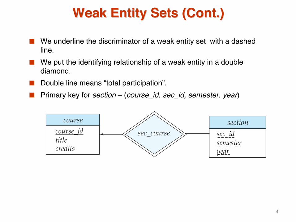
■ We underline the discriminator of a weak entity set with a dashed line.
■ We put the identifying relationship of a weak entity in a double diamond.
■ Double line means “total participation”.■ Primary key for section – (course_id, sec_id, semester, year)
coursecourse_idtitlecredits
sectionsec_idsemesteryear
sec_course
4

Weak Entity Sets (Cont.)
■ Note: the primary key of the strong entity set is not explicitly stored with the weak entity set, since it is implicit in the identifying relationship.
■ If course_id were explicitly stored, section could be made a strong entity, but then the relationship between section and course would be duplicated by an implicit relationship defined by the attribute course_id common to course and section
5

E-R Diagram for a University Enterprise
time_slotcourse
studentIDnamesalary
IDnametot_cred
course_idtitlecredits
time_slot_id{ daystart_timeend_time
}course_id prereq_id
advisor
teaches takes
sec_course sec_time_slot
grade
prereq
inst_dept stud_dept
instructor
departmentdept_namebuildingbudget
sectionsec_idsemesteryear
course_dept
sec_class
classroombuildingroom_numbercapacity 6

Reduction to Relational Schemas
7

Reduction to Relation Schemas
■ Entity sets and relationship sets can be expressed uniformly as relation schemas that represent the contents of the database.
■ A database which conforms to an E-R diagram can be represented by a collection of schemas.
■ For each entity set and relationship set there is a unique schema that is assigned the name of the corresponding entity set or relationship set.
■ Each schema has a number of columns (generally corresponding to attributes), which have unique names.
8

Representing Entity Sets With Simple Attributes
■ A strong entity set reduces to a schema with the same attributesstudent(ID, name, tot_cred)
■ A weak entity set becomes a table that includes a column for the primary key of the identifying strong entity set section ( course_id, sec_id, sem, year )
coursecourse_idtitlecredits
sectionsec_idsemesteryear
sec_course
9

Representing Relationship Sets
■ A many-to-many relationship set is represented as a schema with attributes for the primary keys of the two participating entity sets, and any descriptive attributes of the relationship set.
■ Example: schema for relationship set advisoradvisor = (s_id, i_id)
instructorIDnamesalary
student
IDnametot_cred
advisor
10

Redundancy of Schemas
■ Many-to-one and one-to-many relationship sets that are total on the many-side can be represented by adding an extra attribute to the �many� side, containing the primary key of the �one� side
■ Example: Instead of creating a schema for relationship set inst_dept, add an attribute dept_name to the schema arising from entity set instructor
studentIDnamesalary
IDnametot_cred
advisor
inst_dept stud_dept
instructor
departmentdept_namebuildingbudget
course_dept
11

Redundancy of Schemas (Cont.)
■ For one-to-one relationship sets, either side can be chosen to act as the �many� side● That is, extra attribute can be added to either of the tables
corresponding to the two entity sets ■ If participation is partial on the �many� side, replacing a schema by an
extra attribute in the schema corresponding to the �many� side could result in null values
■ The schema corresponding to a relationship set linking a weak entity set to its identifying strong entity set is redundant.● Example: The section schema already contains the attributes that
would appear in the sec_course schema
12

Composite and Multivalued Attributes
■ Composite attributes are flattened out by creating a separate attribute for each component attribute● Example: given entity set instructor with
composite attribute name with component attributes first_name and last_name the schema corresponding to the entity set has two attributes name_first_name and name_last_name4 Prefix omitted if there is no ambiguity
■ Ignoring multivalued and derived attributes, extended instructor schema is● instructor(ID,
first_name, middle_initial, last_name,street_number, street_name,
apt_number, city, state, zip_code, date_of_birth)
instructorIDname
first_namemiddle_initiallast_name
addressstreet
street_numberstreet_nameapt_number
citystatezip
{ phone_number }date_of_birthage ( )
13

Composite and Multivalued Attributes
■ A multivalued attribute M of an entity E is represented by a separate schema EM● Schema EM has attributes corresponding to the primary key of E
and an attribute corresponding to multivalued attribute M● Example: Multivalued attribute phone_number of instructor is
represented by a schema:inst_phone= ( ID, phone_number)
● Each value of the multivalued attribute maps to a separate tuple of the relation on schema EM4 For example, an instructor entity with primary key 22222 and
phone numbers 456-7890 and 123-4567 maps to two tuples: (22222, 456-7890) and (22222, 123-4567)
14

Multivalued Attributes (Cont.)
■ Special case:entity time_slot has only one attribute other than the primary-key attribute, and that attribute is multivalued● Optimization: Don�t create the relation corresponding to the entity,
just create the one corresponding to the multivalued attribute● time_slot(time_slot_id, day, start_time, end_time)● Caveat: time_slot_id attribute of section (from sec_time_slot)
cannot be a foreign key due to this optimization
time_slottime_slot_id{ daystart_timeend_time
}
sec_time_slot
sectionsec_idsemesteryear
sec_class 15

Design Issues
■ Use of entity sets vs. attributes
■ Use of phone as an entity allows extra information about phone numbers (plus multiple phone numbers)
instructor
IDnamesalary
phonephone_numberlocation
instructor
IDnamesalaryphone_number
inst_phone
16

Design Issues
■ Use of entity sets vs. relationship setsPossible guideline is to designate a relationship set to describe an action that occurs between entities
registration.........
sectionsec_idsemesteryear
studentIDnametot_cred
section_reg student_reg
17

Design Issues
■ Binary versus n-ary relationship setsAlthough it is possible to replace any nonbinary (n-ary, for n > 2) relationship set by a number of distinct binary relationship sets, a n-ary relationship set shows more clearly that several entities participate in a single relationship.
■ Placement of relationship attributese.g., attribute date as attribute of advisor or as attribute of student
18

Binary Vs. Non-Binary Relationships
■ Some relationships that appear to be non-binary may be better represented using binary relationships● E.g., A ternary relationship parents, relating a child to his/her
father and mother, is best replaced by two binary relationships, father and mother4 Using two binary relationships allows partial information (e.g.,
only mother being know)● But there are some relationships that are naturally non-binary
4 Example: proj_guide
19

Converting Non-Binary Relationships to Binary Form
■ In general, any non-binary relationship can be represented using binary relationships by creating an artificial entity set.● Replace R between entity sets A, B and C by an entity set E, and
three relationship sets: 1. RA, relating E and A 2. RB, relating E and B 3. RC, relating E and C
● Create a special identifying attribute for E● Add any attributes of R to E ● For each relationship (ai , bi , ci) in R, create
1. a new entity ei in the entity set E 2. add (ei , ai ) to RA
3. add (ei , bi ) to RB 4. add (ei , ci ) to RC
B R C
A
CB E
A
RA
RB RC
(a) (b) 20

Converting Non-Binary Relationships (Cont.)
■ Also need to translate constraints● Translating all constraints may not be possible● There may be instances in the translated schema that
cannot correspond to any instance of R4 Exercise: add constraints to the relationships RA, RB and RC to
ensure that a newly created entity corresponds to exactly one entity in each of entity sets A, B and C
● We can avoid creating an identifying attribute by making E a weak entity set (described earlier) identified by the three relationship sets
21

Extended ER Features
22

Extended E-R Features: Specialization
■ Top-down design process; we designate subgroupings within an entity set that are distinct from other entities in the set.
■ These subgroupings become lower-level entity sets that have attributes or participate in relationships that do not apply to the higher-level entity set.
■ Depicted by a triangle component labeled ISA (E.g., instructor �is a�person).
■ Attribute inheritance – a lower-level entity set inherits all the attributes and relationship participation of the higher-level entity set to which it is linked.
23

Specialization Example
personIDnameaddress
student
instructorrank
secretaryhours_per_week
employeesalary tot_credits
24

Extended ER Features: Generalization
■ A bottom-up design process – combine a number of entity sets that share the same features into a higher-level entity set.
■ Specialization and generalization are simple inversions of each other; they are represented in an E-R diagram in the same way.
■ The terms specialization and generalization are used interchangeably.
25

Specialization and Generalization (Cont.)
■ Can have multiple specializations of an entity set based on different features.
■ E.g., permanent_employee vs. temporary_employee, in addition to instructor vs. secretary
■ Each particular employee would be ● a member of one of permanent_employee or
temporary_employee, ● and also a member of one of instructor or secretary
■ The ISA relationship also referred to as superclass - subclassrelationship
26

Design Constraints on a Specialization/Generalization
■ Constraint on which entities can be members of a given lower-level entity set.● condition-defined
4 Example: all customers over 65 years are members of senior-citizen entity set; senior-citizen ISA person.
● user-defined■ Constraint on whether or not entities may belong to more than one
lower-level entity set within a single generalization.● Disjoint
4 an entity can belong to only one lower-level entity set4 Noted in E-R diagram by having multiple lower-level entity sets
link to the same triangle● Overlapping
4 an entity can belong to more than one lower-level entity set
27

Design Constraints on a Specialization/Generalization (Cont.)
■ Completeness constraint -- specifies whether or not an entity in the higher-level entity set must belong to at least one of the lower-level entity sets within a generalization.● total: an entity must belong to one of the lower-level entity sets● partial: an entity need not belong to one of the lower-level entity
sets
28

Aggregation
■ Consider the ternary relationship proj_guide, which we saw earlier
■ Suppose we want to record evaluations of a student by a guide on a project
project
evaluation
instructor student
eval_ for
proj_ guide
29

Aggregation (Cont.)
■ Relationship sets eval_for and proj_guide represent overlapping information● Every eval_for relationship corresponds to a proj_guide
relationship● However, some proj_guide relationships may not correspond to
any eval_for relationships 4 So we can�t discard the proj_guide relationship
■ Eliminate this redundancy via aggregation● Treat relationship as an abstract entity● Allows relationships between relationships ● Abstraction of relationship into new entity
30

Aggregation (Cont.)
■ Without introducing redundancy, the following diagram represents:● A student is guided by a particular instructor on a particular project ● A student, instructor, project combination may have an associated
evaluation
evaluation
proj_ guideinstructor student
eval_ for
project
31

Representing Specialization via Schemas
■ Method 1: ● Form a schema for the higher-level entity set● Form a schema for each lower-level entity set, include primary key
of higher-level entity set and local attributes
schema attributesperson ID, name, street, city student ID, tot_credemployee ID, salary
● Drawback: getting information about an employee requires accessing two relations, the one corresponding to the low-level schema and the one corresponding to the high-level schema
32

Representing Specialization as Schemas (Cont.)
■ Method 2: ● Form a schema for each entity set with all local and inherited
attributesschema attributesperson ID, name, street, citystudent ID, name, street, city, tot_credemployee ID, name, street, city, salary
● If specialization is total, the schema for the generalized entity set (person) not required to store information4 Can be defined as a �view� relation containing union of
specialization relations4 But explicit schema may still be needed for foreign key
constraints● Drawback: name, street and city may be stored redundantly for
people who are both students and employees
33

Schemas Corresponding to Aggregation
■ To represent aggregation, create a schema containing● primary key of the aggregated relationship,● the primary key of the associated entity set● any descriptive attributes
34

Schemas Corresponding to Aggregation (Cont.)
■ For example, to represent aggregation eval_for between relationship proj_guide and entity set evaluation, create a schemaeval_for (s_ID, project_id, i_ID, evaluation_id)
■ Schema proj_guide is redundant provided we are willing to store null values for attribute evaluation_id in relation on schema eval_for
evaluation
proj_ guideinstructor student
eval_ for
project
35

E-R Design Decisions
■ The use of an attribute or entity set to represent an object.■ Whether a real-world concept is best expressed by an entity set or a
relationship set.■ The use of a ternary relationship versus a pair of binary relationships.■ The use of a strong or weak entity set.■ The use of specialization/generalization – contributes to modularity in
the design.■ The use of aggregation – can treat the aggregate entity set as a single
unit without concern for the details of its internal structure.
36

Summary of Symbols Used in E-R Notation
E
R
R
A1A2
A2.1A2.2
{A3}A4
Eentity set
relationship set
identifyingrelationship setfor weak entity set primary key
discriminatinga!ribute ofweak entity set
total participationof entity set inrelationship
a!ributes:simple (A1),composite (A2) andmultivalued (A3)derived (A4)
A1
E
A1
ER E
()
37
Symbols Used in E-R Notation (Cont.)
R
R
R
role-name
R
E
Rl..h E
E1
E2 E3
E1
E2 E3
E1
E2 E3
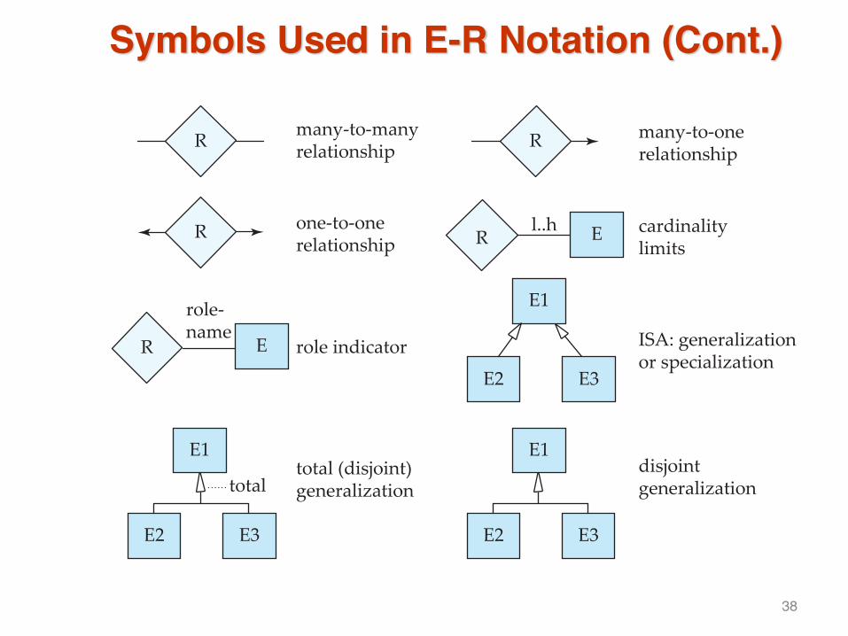
many-to-manyrelationship
many-to-onerelationship
one-to-onerelationship
cardinalitylimits
ISA: generalizationor specialization
disjointgeneralization
total (disjoint)generalization
role indicator
total
38

Alternative ER Notations
■ Chen, IDE1FX, …
entity set E withsimple a!ribute A1,composite a!ribute A2,multivalued a!ribute A3,derived a!ribute A4,and primary key A1
A1A2
A3
A2.1 A2.2
A4E
generalization ISA ISAtotalgeneralizationweak entity set
39

Alternative ER Notations
Chen IDE1FX (Crows feet notation)
participationin R: total (E1)and partial (E2)
E1 E2 E2E1RR
Rmany-to-manyrelationship
one-to-onerelationship
many-to-onerelationship
R
R
*
*
*
1
1
1
R
E1
E1
E1
E2
E2
E2 E1 E2
RE1 E2
RE1 E2
40

UML
■ UML: Unified Modeling Language■ UML has many components to graphically model different aspects of
an entire software system■ UML Class Diagrams correspond to E-R Diagram, but several
differences.
41
ER vs. UML Class Diagrams
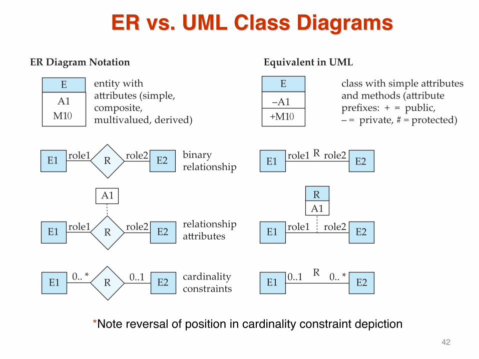
*Note reversal of position in cardinality constraint depiction
–A1+M1
E
binaryrelationship
class with simple a!ributesand methods (a!ributeprefixes: + = public,– = private, # = protected)
A1M1
E entity witha!ributes (simple,composite,multivalued, derived)
RE2E1 role1 role2
relationshipa!ributes E2E1 role1 role2
A1R
R cardinalityconstraintsE2E1
RE2E10.. * 0..1 0..1 0.. *
ER Diagram Notation Equivalent in UML
R E2E1 role1 role2
R E2E1 role1 role2
A1
() ()
42

ER vs. UML Class Diagrams
ER Diagram Notation Equivalent in UML
*In UML, generalization can use merged or separate arrows independentof disjoint/overlapping
E2 E3
E1
E2 E3
E1
E2 E3
overlappinggeneralization
disjointgeneralization
RE3
E1E2
RE3
E1E2n-ary
relationships
E1
E2 E3
overlapping
disjointE1
43

UML Class Diagrams (summary)
■ Binary relationship sets are represented in UML by just drawing a line connecting the entity sets. The relationship set name is written adjacent to the line.
■ The role played by an entity set in a relationship set may also be specified by writing the role name on the line, adjacent to the entity set.
■ The relationship set name may alternatively be written in a box, along with attributes of the relationship set, and the box is connected, using a dotted line, to the line depicting the relationship set.
44

End
45


![id= 3791459 1&course_id= 1039195 1]. To view the movie associated with a page in the notes, click on the play icon in the upper right hand corner of the page. Required Text Book: A](https://img.pdfslide.net/doc/110x75/5add095d7f8b9a595f8c5b36/id-3791459-1courseid-1039195-1-to-view-the-movie-associated-with-a-page-in.jpg)