Embed Size (px)
Citation preview

ASAP Canopies’ E-Series Powered Parachute Canopy Ow ner’s Manual April 10, 2014 Page 1 of 38
Thunderbolt E-Series
Powered Parachute Canopy Owners Manual
ASAP Canopies P.O. Box 106, Yale, MI 48097
Phone: 888-254-2982 Fax: 810-266-0373
Email: [email protected] www.ppccanopies.com

ASAP Canopies’ E-Series Powered Parachute Canopy Ow ner’s Manual April 10, 2014 Page 2 of 38
Edited by: Martin D. Ignazito (Revised 06/23/2005)
Table of Contents:
TABLE OF CONTENTS ………………………………………………..………….………….2 DISCLAIMER...……………………………………….......................…………....……………3 WARNING ………………………………………………………………………………………4 OBLIGATION OF THE OWNER ………………………………………………….…...…5 - 6 INTRODUCTION ……………………………………………………………....……………….7 PARACHUTE COMPONENT DESCRIPTION AND TERMINOLOGY ... ..…......……8 - 9 TECHNICAL AND MATERIALS DATA....................... ...................................................10 SPREAD AND RISER CHART ……………….…………………………………………..…11 LINE LAYOUT DRAWINGS .............................. ........................................................12-23 LAYOUT AREA DRAWINGS .............................. ...........................................................24 PROJECTED AREA DRAWINGS............................ .......................................................25 ASSEMBLY INSTRUCTIONS ……………………………………………….......…….. ..26-28 ASSEMBLY PRE-FLIGHT ……………………………………………...…...………...… 29-30 .. MAINTENENCE & INSPECTION ………………………………...………...………......31-32 REPAIRS AND LINE REPLACEMENT....................... ....................................................33 PRE-FLIGHT INSPECTION…..……………………………….....……………………..........34 FLIGHT OPERATIONS.................................. ............................................................35-37 CLOSING COMMENTS...................................................................................................37 OWNERS REGISTRATION FORM.................................................................................38
TABLE OF CONTENTS

ASAP Canopies’ E-Series Powered Parachute Canopy Ow ner’s Manual April 10, 2014 Page 3 of 38
Because of the unavoidable danger associated with the use of the herein referenced ASAP Canopies-E Series powered parachute canopy, the manufacturer makes NO WARRANTY, either expressed or implied. The ASAP Canopies-E Series powered parachute canopy is sold with all faults and without any warranty of merchantability and fitness for any purpose. Manufacturer also disclaims any liability in tort of damages, direct or consequential, including personal injuries resulting from a defect in design, material, workmanship or manufacturing whether caused by negligence on the part of the manufacturer or otherwise. By using this product, or allowing it to be used by others, the buyer WAIVES any liability of the manufacturer for personal injuries or other damages arising from such use.
DISCLAIMER - NO WARRANTY

ASAP Canopies’ E-Series Powered Parachute Canopy Ow ner’s Manual April 10, 2014 Page 4 of 38
THE SPORT OF POWERED PARACHUTE (PPC) FLYING IS A
POTENTIALLY DANGEROUS ACTIVITY!! Participation as a pilot or occupant could result in injury and/or death to the participant. Each individual, regardless of experience, has the final responsibility for his or her own actions and safety while engaged in any aspect of PPC flying activities. All flying activities involve traveling through airspace with some amount of horizontal and vertical motion governed by the laws of physics and subject to unpredictable forces of nature. Flying is also highly dependent upon the skills of the pilot or instructor and the behavior of any students. Regardless of the quality of the equipment, materials used knowledge or experience of the pilot in command, THE RISK OF SERIOUS BODILY INJURY AND/OR DEATH IS ALWAYS PRE SENT DURING THIS ACTIVITY. There are inherent risks in the participation in recreational aviation aircraft. Operators and passengers of recreational aviation aircraft, by participation, accept the risks inherent in such participation of which the ordinary prudent person is or should be aware. Pilots and passengers have a duty to exercise good judgments and act in a responsible manner while using the aircraft and to obey all oral or written warnings, or both, prior to or during use of the aircraft, or both. PPC vehicles using the ASAP Canopies-E Series canop y are constructed of numerous components, supplied by man y different manufacturers. Each and every component must be ins pected to ensure that it is in good working order. ASAP Canop ies cannot guarantee the workmanship, suitability or airworthi ness of any component of the PPC vehicle.
! IMPORTANT WARNINGS !

ASAP Canopies’ E-Series Powered Parachute Canopy Ow ner’s Manual April 10, 2014 Page 5 of 38
OBLIGATIONS OF THE OWNER It is mandatory that you read this manual before assembly and use of the referenced powered parachute and its canopy. It is beyond the scope of this manual to teach you how to fly a powered parachute ultralight or develop the judgment required to determine safe or unsafe conditions prior to and during each flight. In addition, this manual is not a complete text on the care and maintenance of your powered parachute, its canopy, airframe and power plant. As such it is important that you seek out all information relevant to flying and maintaining powered parachute ultralights. The following is a guide on procedures that should help lower, but not necessarily eliminate the risk of injury or death to yourself and others. TRAINING: The training, experience and competence of the pilot of an ultralight vehicle are extremely important to flight safety. NEVER use this equipment unless you have: 1. Read this manual, all owners/flight manuals, operating manuals and completed a “controlled program of instruction” for the powered parachute ultralight aircraft you will be flying. - OR - Read this manual and all owners/flight manuals, operating manuals, have 100 flight hours in a similar aircraft and have at least a current instructors or pilot's certificate from an FAA recognized authority. 2. Read and understand all applicable federal, state and local regulation pertaining to the operation of Ultralight aircraft. Reference Federal Aviation Administration Part 103 regulations governing ultralight vehicle operation and any applicable exemptions. 3. Read and understand the maintenance manual and the requirements of your particular powered parachute ultralight. Read and understand the pilot operating handbook and the requirements of your particular powered parachute ultralight. 4. Obtain instruction on weather and meteorology and their effect on flight conditions. This manual does not attempt to provide instruction on micro meteorology or the physics of flight. It is the responsibility of the pilot to obtain instruction in these topics and to study the conditions of any areas that will be traversed during a flight. PREFLIGHT: Prior to every flight, the “Pilot in Command” is responsible for performing a complete preflight inspection of the vehicle and canopy to ensure that it is airworthy. The Pilot in Command/ Basic Flight Instructor is also responsible for providing proper training to any and all students.

ASAP Canopies’ E-Series Powered Parachute Canopy Ow ner’s Manual April 10, 2014 Page 6 of 38
FLIGHT: This canopy must always be FULLY INFLATED and free of any irregularities before take-off. All take-offs and landings must be made directly into the prevailing wind. All normal control inputs should be smooth yet deliberate. This canopy was designed specifically as the main canopy of a powered aircraft. No other use of this canopy is authorized. POST FLIGHT: You should perform a post flight inspection on all components to check for wear and needed maintenance before packing and storage of your canopy. MAINTENANCE: Maintenance of any aircraft or ultralight vehicle is extremely important to the safety of the pilot, instructor and students. It is the owner and pilot’s responsibility that all scheduled inspections and maintenance be performed in strict compliance with the instructions of the airframe, engine and canopy manufacturers.
THE RESPONSIBILITIES OF THE PILOT ARE NOT LIMITED TO THOSE STATED ABOVE, AS SUCH, THE PILOT SHOULD MAKE EVERY EFFORT TO CONSULT THE PROPER AUTHORITY AND ORGANIZATION IN THE SAFE USE OF POWERED PARACHUTE ULTRALIGHTS.
DEVIATION FROM THE MANUFACTURER’S MAINTENANCE INSTRUCTIONS OR ALTERATION TO ANY COMPONENT OF THE CANOPY IS NOT AUTHORIZED.
Canopies must be inspected every 100 hours and annually to insure airworthiness. ASAP Canopies recommends replacement at 5 years or 500 hours. This may be extended with an airworthiness inspection which includes a fabric pull test.

ASAP Canopies’ E-Series Powered Parachute Canopy Ow ner’s Manual April 10, 2014 Page 7 of 38
INTRODUCTION Congratulations on the purchase of your new E Series Canopy. You have chosen what we believe to be the highest quality and best performing product of its type. Your product satisfaction and safety are important to us. As such, this manual provides information on the assembly, maintenance and use of the ASAP Canopies -E Series canopy. IT IS CRITICAL TO FLIGHT SAFETY THAT THIS CANOPY IS ONLY USED ON APPROVED VEHICLES. NEVER MAKE ANY MODIFICAT ION OR REPAIR TO THE CANOPY, SUSPENSION LINES, OR STEER ING SYSTEM UNLESS SPECIFICALLY DIRECTED BY INSTRUCTION IN THIS MANUAL OR THROUGH WRITTEN APPROVAL DIRECTLY FR OM ASAP Canopies. If you have any questions or comments relative to your E Series canopy please address them to:
ASAP Canopies P.O. Box 106, Yale, MI 48097
Phone: 810-679-9638 Fax: 810-679-9639
Email: [email protected]

ASAP Canopies’ E-Series Powered Parachute Canopy Ow ner’s Manual April 10, 2014 Page 8 of 38
Description
The E Series powered parachute canopy is constructed from a top and bottom surface which are connected by profiled ribs. One top and bottom panel, between two connecting ribs are called a cell. Each of these cells has an opening on the lower side of the leading edge. The cells fill with air under pressure forcing the panels to take the shape dictated by the airfoil section of the ribs. The ribs are reinforced with tape above the line hook-up points. On both wingtips there are stabilizers that increase the span wise tension and also improve the Yaw stability.
IMPORTANT!
Terminology Span : The planform distance from canopy tip to canopy tip measured at the quarter chord. Chord : The straight line distance from the forward most portion of the airfoil leading edge, to the trailing edge. Upper Surface : The entire top surface of your canopy. Lower Surface : The entire bottom surface of your canopy. Airfoil Ribs : There are two types of airfoil ribs incorporated in your ASAP Canopies -E Series Powered Parachute Canopy: Load Ribs and Non-load Ribs. Both are designed to maintain the desired airfoil shape of your canopy. All internal airfoil ribs are also cross ported to allow the transmission of air pressure between cells during inflation and to provide pressure equalization during flight.
PARACHUTE DESCRIPTION AND TERMINOLOGY
ALL REFERENCES TO THE RIGHT (STARBOARD) OR LEFT (PORT) SIDES OF THE CANOPY ARE TAKEN FROM THE PILOT’S POINT-OF-VIEW WHEN FLYING THE AIRCRAFT.

ASAP Canopies’ E-Series Powered Parachute Canopy Ow ner’s Manual April 10, 2014 Page 9 of 38
Load Ribs : Ribs with line attachment loops and reinforcements designed to transfer load into the rib. Non Load Ribs : Ribs positioned between Load Ribs to maintain the desired airfoil shape.
Cell : Bounded by the upper and lower surfaces, the length of the chord and the distance between adjacent Ribs. Stabilizer: Fabric panels extending down from each canopy tip to enhance directional stability. Suspension Lines : Your E Series Powered Parachute Canopy has four primary suspension lines attached chordwise to each Load Rib: See the line layout drawings for details. Connector (Quick) Links : Your E Series Powered Parachute Canopy is assembled and delivered with all suspension lines already attached to four Stainless Steel Maillon Rapide, connector links, often referred to as “Quick Links”. Connector Link Sleeves : These 2 ½” polyvinyl or surgical tubing sleeves position the lines on the connector links and minimize suspension line wear.
IMPORTANT! THIS IS A CRITICAL FLIGHT SAFETY ITEM! USE CONNECTO R LINKS SUPPLIED BY ASAP CANOPIES OR YOUR POWERED PARACHUTE MANUFACTURER ONLY! NEVER USE SIMILAR HARDWARE STORE QUICK LINKS.

ASAP Canopies’ E-Series Powered Parachute Canopy Ow ner’s Manual April 10, 2014 Page 10 of 38
Technical & Materials Data
1/Fabric Type: Nylon Ripstop cloth made of Nylon 6.6 High Tenacity Yarn with Polyurethane coating. Weight: 42+/- 1.5 gr/m2 Breaking Strength (Kg/5 cm): Warp 42+/-4, Weft 36+/-4 Tearing Strength (Kg) : Warp 3.0 , Weft 3.0 Air Permeability (CC/CM2/SEC) : Less than 0.03 2/Reinforcement Tape / Line attachment Tape: Made of Nylon 6.6 High Tenacity Yarn Weight : 8.6 gr/m Breaking Strength : 200 Kgs (Min.) Width : 15mm +/- 1.5mm 3/Sewing Thread: Made of High Tenacity Polyester Yarn Denier : 250 Denier 2 Ply Breaking Strength : 3.0 Kgs 4/Suspension Lines: Made of Superaramid core with Polyester cover (#)(Diameter/Breaking Strength): (1) 2.3mm/300 Kgs (2) 2.0mm/220 kgs (3) 1.7mm/180 kgs (4) 1.5mm/140 Kgs (5) 1.2mm/80 Kgs, 5/Lower control lines (Steering): Made of High Tenacity Nylon Yarn Diameter: 5mm Breaking Strength : 700 Kgs (Min.) 6/The canopy consists of 35 Cells and 34 Chambers, 28 Loaded Ribs, 6 Non-Loaded Ribs 7/Maillion Rapid Links: Stainless steel Diameter: 8.0 mm Working Load: 1,100 Kgs

ASAP Canopies’ E-Series Powered Parachute Canopy Ow ner’s Manual April 10, 2014 Page 11 of 38
The following chart gives the required riser lower attachment Spread and associated Riser length combinations for correct in-flight geometry. These dimensions expressed in “inches must be strictly adhered to for the proper operation and safety of the Thunderbolt canopies. It is possible to have a variance of 2-3 inches on either dimension and still be within the safety limits of this canopy. If the riser lower attachment spread cannot be modified to suit the chart then the riser length MUST BE modified to suit for proper in-flight geometry!! i.e. The combination of the two (riser lower attachment spread and riser length) MUST match the riser chart below in order to be correct. For example: a 60” attach distance spread for a model E340 must use a 47” canopy riser.
Model E -310 and E-340 Model E -280 Spread Riser Riser
40 84 74
41 82 72
42 80 70
43 79 68
44 77 67
45 75 65
46 73 63
47 71 61
48 69 59
49 68 57
50 66 56
51 64 54
52 62 52
53 60 50
54 58 48
55 57 46
56 55 44
57 53 43
58 51 41
59 49 39
60 47 37
61 46 35
62 44 33
63 42 31
64 40 30
65 38
66 37
67 35
68 33
69 31
70 29

ASAP Canopies’ E-Series Powered Parachute Canopy Ow ner’s Manual April 10, 2014 Page 12 of 38
Line Layout Drawings:

ASAP Canopies’ E-Series Powered Parachute Canopy Ow ner’s Manual April 10, 2014 Page 13 of 38

ASAP Canopies’ E-Series Powered Parachute Canopy Ow ner’s Manual April 10, 2014 Page 14 of 38

ASAP Canopies’ E-Series Powered Parachute Canopy Ow ner’s Manual April 10, 2014 Page 15 of 38

ASAP Canopies’ E-Series Powered Parachute Canopy Ow ner’s Manual April 10, 2014 Page 16 of 38

ASAP Canopies’ E-Series Powered Parachute Canopy Ow ner’s Manual April 10, 2014 Page 17 of 38

ASAP Canopies’ E-Series Powered Parachute Canopy Ow ner’s Manual April 10, 2014 Page 18 of 38

ASAP Canopies’ E-Series Powered Parachute Canopy Ow ner’s Manual April 10, 2014 Page 19 of 38

ASAP Canopies’ E-Series Powered Parachute Canopy Ow ner’s Manual April 10, 2014 Page 20 of 38

ASAP Canopies’ E-Series Powered Parachute Canopy Ow ner’s Manual April 10, 2014 Page 21 of 38
CM MM
REF. LGTH DIA
L3 131.7 2.0
L2 115.1 2.0
L1 109.5 2.0
R1 122.2 2.0
R2 116.1 2.0
R3 122.7 2.0
R4 114.3 2.0
R5 116.7 2.0
R6 123.1 1.7
R7 120.1 1.7
R8 125.5 1.7
R9 131.7 1.5
R10 126.3 1.5
R11 129.2 1.5
R12 122.4 1.5
R13 123.2 1.5
R14 132.4 1.5
R15
R16
R17 400.0 2.3
R18 372.2 2.3
R19 365.0 2.3
R20 358.5 2.3
R21 188.0 2.3
R22 170.9 1.7
R23 180.0 1.7
REV:12/16/13
E340S
CM MM
REF. LGTH DIA
L3 141.1 2.0
L2 127.2 2.0
L1 120.0 2.0
R1 502.4 2.3
R2 124.4 2.0
R3 120.1 2.0
R4 124.5 2.0
R5 123.0 2.0
R6 133.1 1.7
R7 128.5 1.7
R8 134.8 1.7
R9 137.7 1.5
R10 134.3 1.5
R11 133.5 1.5
R12 128.2 1.5
R13 126.7 1.5
R14 135.7 1.5
R15
R16
R17 400.0 2.3
R18 502.4 2.3
R19 372.7 2.3
R20 365.0 2.3
R21 358.5 2.3
R22 188.0 2.3
R23 170.9 1.7
R24 180.0 1.7
REV:12/16/13
E340S
E340S
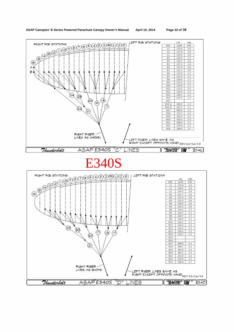
ASAP Canopies’ E-Series Powered Parachute Canopy Ow ner’s Manual April 10, 2014 Page 22 of 38
E340S
CM MM
REF. LGTH DIA
L3 135.8 2.0
L2 117.0 2.0
L1 114.0 2.0
R1 126.6 2.3
R2 118.7 2.0
R3 127.2 2.0
R4 117.0 2.0
R5 121.3 2.0
R6 127.0 1.7
R7 125.4 1.7
R8 128.6 1.7
R9 135.1 1.5
R10 129.8 1.5
R11 133.1 1.5
R12 126.0 1.5
R13 128.1 1.5
R14 135.5 1.5
R15
R16-A 186.8 1.5
R16-B 187.7 1.5
R17 400.0 2.3
R18 372.7 2.3
R19 365.0 2.3
R20 358.5 2.3
R21 188.0 2.3
R23 170.9 1.7
R24 180.0 1.7
E340S
REV.12/16/13
CM MM
REF. LGTH DIA
L3 155.8 2.0
L2 136.6 2.0
L1 134.5 2.0
R1 121.7 2.0
R2 111.6 2.0
R3 121.9 2.0
R4 109.9 2.0
R5 116.3 2.0
R6 119.5 1.7
R7 118.7 1.7
R8 120.7 1.7
R9 128.4 1.5
R10 119.1 1.5
R11 124.2 1.5
R12 114.4 1.5
R13 116.5 1.5
R14 122.2 1.5
R15
R16
R17 400.0 2.3
R18 399.7 2.3
R19 392.0 2.3
R20 385.5 2.3
R21 215.0 2.3
R22 170.9 1.7
R23 180.0 1.7
E340S
REV.12/16/13

ASAP Canopies’ E-Series Powered Parachute Canopy Ow ner’s Manual April 10, 2014 Page 23 of 38
E340S
CM MM
REF. LGTH DIA
L3
L2
L1
R1 209.8 1.2
R2
R3 182.0 1.2
R4
R5 204.9 1.2
R6
R7 188.2 1.2
R8
R9 190.5 1.2
R10
R11 252.8 1.2
R12
R13 204.1 1.2
R14
R15 199.3 1.2
R16
R17 254.1 1.5
R18 223.3 1.5
R19 188.5 1.5
SAFETY 121.0 1.5
STEERING 10.0
E340S
REV.12/16/13

ASAP Canopies’ E-Series Powered Parachute Canopy Ow ner’s Manual April 10, 2014 Page 24 of 38

ASAP Canopies’ E-Series Powered Parachute Canopy Ow ner’s Manual April 10, 2014 Page 25 of 38

ASAP Canopies’ E-Series Powered Parachute Canopy Ow ner’s Manual April 10, 2014 Page 26 of 38
Assembly Instructions: Assembly of your E series Powered Parachute Canopy will require the following tools: 1 each open end wrench 1 screwdriver The correct attachment of your E Series Powered Parachute Canopy to your completed airframe is a critical part of your Powered Parachute construction. Aircraft Sales and Parts has made every effort to make this assembly as easy and trouble free as possible. Time spent reading the following instructions, reviewing the description and terminology provided above and examining the referenced figures will give you the understanding and confidence to complete this assembly. Your ASAP Canopies-E Series Powered Parachute Canopy is packaged in a manner that will assist in assembly to your aircraft.
IMPORTANT! DO NOT TAKE YOUR E-SERIES POWERED PARACHUTE CANOPY OUT OF THE CHUTEBAG UNTIL YOU ARE DIRECTED TO DO SO IN THIS MANUAL. ASSEMBLY TO THE VEHICLE 1. Set the completely assembled airframe in an area large enough to accommodate the airframe and parachute. The parachute needs 35 to 40 by about 15 ft feet of working space. Block the wheels so your airframe cannot move. 2. Place your bagged E Series canopy at the rear of your vehicle about 5 feet behind the propeller. 3a. If you have webbing risers: Take the risers on the right side of your vehicle and properly align the connector links to accept the canopy without twists in the webbing. Make sure the steering line pulley is located toward the outside of the rear riser. Maintaining this orientation secure the risers to the hooks located on your fan guard or at another appropriate location depending on your vehicle. Repeat this operation for the left side. 3b. If you are using cable risers: Take the main and safety cables on the right side of your vehicle and align the cable connector links to accept the canopy without twists in the cables. Maintaining this orientation place the eye of the cables onto the hooks located on the fan (propeller) guard or at another appropriate location depending on your vehicle. Ensure that the steering guide ring or pulley is through both connector links and is hanging toward the bottom. Repeat this operation for the left side main and safety cables.

ASAP Canopies’ E-Series Powered Parachute Canopy Ow ner’s Manual April 10, 2014 Page 27 of 38
4. Open the chute bag and remove the chute. Lay the chute out behind the aircraft with the top surface down, the leading edge to the rear and spread out from left to right so that all lines can be clearly seen from end to end. 5. Remove the line socks and arrange the chute and all it's lines so that they can be clearly seen from one end to the other of each line set. 6. Take the Rapide link with the A & B lines (leading edge and next set rearward) of one side of the chute, pull it towards the airframe and arrange it so that all the lines run from link to chute with no twists or tangles. Open the Rapide link either by hand or with the wrench and screwdriver. Attach it to the front or inner riser cable or strap from your airframe. Check with your airframe manufacturer to determine the correct attachment arrangement. Tighten the Rapide finger tight and then tighten it with the wrench and screwdriver another 1/4 turn maximum. Safety mark the barrel nut on each link using a drop of nail polish, a permanent marker, or similar. Take the C & D lines (next set of suspension lines lower) on the same side and attach these to the rear or outside riser cable or strap from your airframe as indicated above for the A & B lines. Check with your airframe manufacturer to determine the correct attachment arrangement. Repeat the above process on the opposite side of the airframe.
WARNING! OVERTIGHTENING A CONNECTOR LINK CAN CAUSE THE BARRE L TO CRACK AND SEPARATE. INSPECT REGULARLY FOR CRACKS. DO NOT FLY WITH CRACKED BARRELS 7. Your E Series Powered Parachute canopy is now attached to your airframe and ready for line inspection. While an assistant is holding the vehicle to prevent it from rolling or the airframe is chocked in place, walk behind the canopy. Starting at one end pull or gather the canopy back towards you till all the lines are drawn up with as little slack as possible. If you have prop cage hooks, it helps to hang the risers on these. If you do not have prop cage hooks, tying the risers to the cage for this process will make it easier to do. Pull the chute back all along its span so that the suspension lines are hanging in an arc without touching the ground from cage hooks to chute or as close to this as possible. 8. Walk back to the aircraft and loosely grab only the A/B suspension line group on one side of the airframe (these are the lines attached to the top quick link on the Left Webbing Riser or if you are using cables, on the Left Main and Safety cables. Separate these lines from the others by shaking them free. You should now be able to see the A, B and A/B lines distinctly running from the Rapide link to each attach point on the canopy with no tangles, crossovers, twists etc. If there are any problems, call your canopy dealer or ASAP Canopies for instructions.

ASAP Canopies’ E-Series Powered Parachute Canopy Ow ner’s Manual April 10, 2014 Page 28 of 38
9. Hold the A/B suspension line group up out of the way with one hand. With the other hand loosely grab only the Left C/D suspension line group (these are the lines attached to the lower quick link on the Left Webbing Riser or if you are using cables, on the Left Main and Safety cables). Separate these lines from the others by shaking them free. You should now be able to see the C, D and C/D lines distinctly running from the rapide link to each attach point on the canopy with no tangles, crossovers, twists etc. If there are any problems, call your canopy dealer or ASAP Canopies for instructions. Repeat steps 8 & 9 on the opposite side of the airframe. 10. Go towards one canopy tip and moving to the trailing edge, find the safety/rigging line and steering line. Verify that the safety line goes directly to the rear connector link and does not cross over any other lines. Run the steering line thru the pulley on the webbing riser or, if you are using cables, through the steering guide ring and to the inside of the Main and Safety cables. Route this forward thru any pulleys required on your airframe and attach it to your steering system as required by your airframe manufacturer. Route the Steering Line through all pulleys/guides with the foot bars in the full back (aft) position. Repeat this process on the opposite side of the airframe. 11. Set each Steering Line in turn by having your assistant hold the upper end of the steering line at the steering line safety/rigging line cascade junction and pull tension until the safety line is tight. The safety line is your reference for the Steering line length. A piece of tape on the steering line is also a check reference in relation to the guide ring where such rings are used. If your steering lines run thru pulleys, remove this tape being careful not to cut or otherwise damage the steering lines. 12. Make sure that each Steering Line is under tension while your assistant is pulling on the safety/rigging and steering lines. When you are satisfied that the tension in the Steering line is slightly greater than that in the Safety/rigging Line, tie off the Steering Line at its airframe manufacturer recommended home end location. Your steering is at “Factory” setting when the Safety Line has a bow of approximately 1 to 2 inches in flight. Each Lower Steering line is tied to the appropriate link or connection attached to a terminal on the vehicle frame. Tie the Lower Steering line to the link or connection using an anchor knot or bowline and at least two overhand knots. Secure the bitter ends of the Steering Line with three tie wraps, trim flush and melt seal the ends

ASAP Canopies’ E-Series Powered Parachute Canopy Ow ner’s Manual April 10, 2014 Page 29 of 38
WARNING! YOU MUST PERFORM THE FOLLOWING GROUND TAXI CHECK OU T BEFORE ATTEMPTING YOUR FIRST TAKE OFF. IF YOU ARE N OT QUALIFIED TO PERFORM THIS TASK, HAVE YOUR DEALER OR A COMPETENT PILOT PERFORM IT FOR YOU. Assembly of the E Series Powered Parachute Canopy to your airframe is now complete. However, before you fly your new Powered Parachute, you need to perform a thorough pre-flight inspection to ensure that your canopy is correctly attached to your airframe and there are no twists in the suspension or steering lines. Continue with Assembly Pre-Flight as follows:
ASSEMBLY CONTINUED…ROLLING PRE-FLIGHT WARNING: THE FOLLOWING SHOULD ONLY BE PERFORMED BY AN EXPERIENCED ELLIPTICAL CANOPY PILOT OR UNDER THE DI RECT SUPERVISION OF AN ELLIPTICAL CANOPY QUALIFIED INSTR UCTOR. 13. Choose a day when the wind is light, not more than 5 knots and is a DIRECT HEAD WIND. Make sure there is sufficient runway length and width to safely conduct this operation. Elliptical chutes require more runway length and width than "normal" for these tests due to higher than "normal" speeds that will be encountered. Seek advice from an elliptical canopy qualified instructor as to what is required. 14. Lay out your canopy and perform the preflight check in accordance with the vehicle manufacturers' instructions and these instructions. You will find a CANOPY PREFLIGHT CHECKLIST in this manual. 15. With your helmet and all appropriate equipment on, start and warm up your engine per the vehicle manufacturer’s instructions. It may be more convenient to do your actual 5 minute long engine warm up before the layout above. 16. Add power to inflate your canopy and begin to taxi your vehicle. Maintain only enough power to taxi your aircraft and keep your canopy inflated and directly overhead.. DO NOT TAKE OFF. Caution: With full elliptical chutes such as the E Series, taxiing "chute up" is a difficult maneuver requiring significant skill and experience with elliptical chute operation. Much higher than "normal" taxi speeds are required making ground control more challenging of pilot skill. If not done properly the chances of damage to the chute can be significant due to chute collapse. If you do not have this experience or do not have a pilot available to do this test who is experienced, see the alternate method described below. 17. After checking that your ground path is clear, start a visual inspection of your canopy.

ASAP Canopies’ E-Series Powered Parachute Canopy Ow ner’s Manual April 10, 2014 Page 30 of 38
18. Start at the cables and steering line on one side checking for their correct position and routing. 19. Scanning from one tip to the other, make sure that the suspension lines go directly from the cables to the canopy without any twist. 20. Ensure the steering lines join the upper steering lines directly and are not wrapped around any suspension lines. 21. Check that all cells are fully inflated both spanwise and chordwise. 22. Check the cables and steering line on the opposite side. 23. Continue to check that your ground track is clear.
CAUTION! THESE NEXT GROUND MANEUVERS MUST BE PERFORMED INTO THE WIND. DO NOT OVER-STEER THE CANOPY WHILE TAXIING. THIS CO ULD CAUSE YOUR VEHICLE TO ROLL OVER. IF YOU FEEL THAT YOU ARE LOSI NG CONTROL, SHUT DOWN THE ENGINE IMMEDIATELY. 24. Now check the steering system for control authority by applying a very small amount of steering input to one foot pedal until that side deflects and begins to turn. Maintain only enough power to taxi your aircraft and keep your canopy inflated. Repeat for the other side. Check to see that steering lines are rigged tightly enough for proper steering authority. 25. Once you are satisfied that your canopy is attached and taxing correctly, shutdown your engine and collapse your chute using normal procedures for this. Your canopy should now be ready to fly.
ALTERNATE ... ROLLING PREFLIGHT: 1. Perform all operations up through 15 above. Slowly add power up to full power and observe the canopy as it rotates upwards. 2. As soon as the canopy reaches the overhead position, immediately close the throttle, shut down the magnetos, apply full steering "brake" to both foot bars and "reel in" steering line by hand to collapse the chute behind you. The use of steering inputs in this and the previous operation 2 above comprise the testing of the steering system as described in 24 and 25 above. 3. Repeat steps 1 thru 3 immediately above as many times as required to go thru all of the items in 17 - 23 above. Do Not Take Off during any of these tests. CAUTION: Do not attempt to fly your E Series canopy until you have received instruction from a qualified instructor familiar wi th elliptical canopy operations.

ASAP Canopies’ E-Series Powered Parachute Canopy Ow ner’s Manual April 10, 2014 Page 31 of 38
CANOPY MAINTENANCE & INSPECTION WARNING! IF YOU HAVE ANY DOUBT AS TO THE AIRWORTHINESS OF YO UR CANOPY, DO NOT FLY IT. CONTACT YOUR POWERED PARACHUTE MANUFACT URER OR ASAP CANOPIES TO DETERMINE AIRWORTHINESS.
MAINTENANCE Canopy Storage The parachute should always be stored out of direct sunlight and in an area free from moisture and mildew when not in use. Prolonged exposure of the canopy to sunlight will weaken the fabric and shorten the life span of the canopy. Cleaning The zero porosity fabric of your E Series Powered Parachute Canopy is not affected by water but, the reinforcing tapes and thread are. To maintain the best performance, avoid getting your canopy wet. Only spot clean your canopy. Use a clean, wet, cloth rag or soft bristled brush. Use only mild soap and luke-warm water. Avoid getting the tapes wet. Do not machine wash. For hard to clean spots use dry cleaning solution. Rinse thoroughly. Fabric: Your E Series Canopy is made of very light-weight Ripstop nylon material which has been treated with silicone coatings to prevent air from leaking through the fabric. This fabric is degraded by exposure to sunlight, water and dirt as well as a wide variety of chemicals that may be found anywhere the canopy is flown or stored. Fabric degradation often occurs very subtlety over a period of time and may not result in obvious blemishes or tears. A regular inspection of the parachute fabric is necessary to ensure the fabric remains in good repair, retains an acceptable level of impermeability to air leakage and that the canopy remains airworthy. Neon colors are more susceptible to these elements than are the standard colors. To inspect the E Series Canopy fabric: 1. Clear a clean, dry area large enough to lay out the canopy on its upper surface. 2. Inspect the lower surface, cell by cell, looking for small holes, dirt or discoloration. Do Not Walk on the canopy. 3. Turn the canopy over and inspect the upper surface as you did the lower surface.

ASAP Canopies’ E-Series Powered Parachute Canopy Ow ner’s Manual April 10, 2014 Page 32 of 38
Seams and Joints Inspect all seams looking for any broken or worn stitching. Cell Interior and Crossports Crossports are made in the airfoil shaped ribs by cutting a hole in the fabric with a hot knife which sears the edges of the cut. Crossports may tear from high stress and/or fray. Look inside each cell, inspecting the fabric ribs, upper and lower surface for small holes and discoloration. Look closely for debris, small dirt clods and insects that often become trapped inside the cells during take-off and landing. Remove all foreign objects. Inspect each cross-port for tears and fraying. Suspension lines Suspension lines are made from braided Aramid yarn. Stretch out the lines so that they lay flat on the ground. Walk the length of the lines running your fingers along the lines, visually inspecting the lines and feeling for abrasion, fraying, burrs and debris. Look for breaks in stitching at cascade junctions and attachment points. Look for discoloration. Steering Lines Upper steering lines are also made from Aramid yarn and are inspected in the same manner as the suspension lines. Lower steering lines are made from a low stretch 5mm High Tenacity Polyester cord. This cord has many filaments running inside a braided sheath and is designed to be used with pulleys. Inspect the lower steering lines for wear to the sheath especially where it travels through the pulleys or rings of your control system. Check the flexibility of the lower steering line, it should be pliable and not stiff.

ASAP Canopies’ E-Series Powered Parachute Canopy Ow ner’s Manual April 10, 2014 Page 33 of 38
Repairs and Line Replacement IMPORTANT! ALL REPAIRS TO YOUR AIRCRAFT SALES AND PARTS POWERE D PARACHUTE CANOPY MUST BE PERFORMED BY QUALIFIED PERSONNEL AND USE ONLY ORIGINAL ASAP CANOPIES PARTS AND MATERIALS. WHERE TO HAVE YOUR CANOPY INSPECTED AND REPAIRED: a) ASAP Canopies b) Trained and qualified powered parachute service representatives. (Call ASAP Canopies to confirm qualifications) c) Transport Canada or Federal Aviation Administration (FAA) certified parachute loft or Balloon repair stations. If you can not locate a qualified repair facility in your area, feel free to call ASAP Canopies’ Customer Service for the nearest repair facility in your area or to arrange service at the ASAP Canopies’ factory. Repairs to the canopy's external and internal surfa ces To assure your safety, all repairs to your canopy whether major or minor should be accomplished by one of qualified agencies listed above. Line Replacement Your E Series Powered Parachute Canopy has been designed and manufactured to allow the easy field replacement of all suspension and steering lines. General description: The suspension and steering lines of your E Series Powered Parachute Canopy are manufactured with a loop at each end. The upper suspension lines (A, B, C, D, E, & F if used) are threaded through the Load Rib line attachment loop. Then, the other end is passed through the line loop and tensioned forming a Larks head Knot. This method is repeated at the line cascades junctions by capturing the two upper suspension lines with a lower suspension line (i.e. A and B line captured by the A/B line). The suspension line terminates at the Maillon Rapide link by sliding the loop onto the link in the proper sequence. Once you have identified a line or lines that are damaged, use the line chart to map its position. The line chart will help you to identify the relative position of the line. You can order a replacement line using this line code. If you have more than one damaged or broken line, please contact us about the best method for replacing the damaged lines.

ASAP Canopies’ E-Series Powered Parachute Canopy Ow ner’s Manual April 10, 2014 Page 34 of 38
WARNING! NEVER FLY WITH DAMAGED LINES. NEVER TIE THE ENDS OF A BROKEN LINE BACK TOGETHER. THIS PRACTICE CAN LEAD TO SERIOUS INJURY OR DEATH! Connector (Quick) Links Use only the Maillon Rapide stainless steel links supplied with your canopy.
WARNING! THE USE OF QUICK LINKS NOT SUPPLIED BY ASAP CANOPIE S CAN LEAD TO SERIOUS INJURY OR DEATH.
CANOPY PREFLIGHT INSPECTION 1. Look at all of the canopy components to determine airworthiness.
WARNING! IF ANYTHING APPEARS UN-AIRWORTHY OR UNUSUAL, DO NOT FLY YOUR AIRCRAFT. CONTACT YOUR DEALER OR THE MANUFACTURER. 2. Check the connector links for proper attachment and any cracks in the barrel nut. The barrel nut position marks you made during assembly should be aligned. If the position mark is not aligned, inspect the link and replace, if required, then tighten as described in the assembly section of this manual. 3. Check suspension and control lines for knots, tangles, debris and wear. 4. Check steering lines for damage, wear, proper routing through all guides or pulleys and for secure attachment to the airframe control system. 5. Perform a complete vehicle inspection according to the manufacturer’s instructions. 6. Heed your intuition and check any component that catches your attention. 7. Pay attention to detail.

ASAP Canopies’ E-Series Powered Parachute Canopy Ow ner’s Manual April 10, 2014 Page 35 of 38
Flight operations: LAUNCHING As this is not a training manual we will not try to teach you any details of launching techniques. The services of a qualified fight instructor should be sought if the pilot is not familiar with launching techniques for full elliptical canopies. We will only briefly go through launch layout techniques to help you get the most out of your powered parachute canopy. LAYOUT Pre-flight check should be done before every flight. Spread the powered parachute canopy out on the ground behind the airframe. Spread the lines, dividing them into four groups of two with "top" lines (A & B) on top and "bottom" lines (C & D) on the bottom, left and right accordingly. Make sure the lines are free and not twisted, tangled with each other or knotted. Make sure all the lines are on top of the powered parachute canopy and that there are none caught on vegetation, rocks or looped under or over the powered parachute canopy. Lay out the powered parachute canopy in a horseshoe shape stacked from trailing to leading edge. This method insures that all the lines are equally tensioned on launch, and results in an even inflation. The Mylar rib section will keep the leading edge open for easy inflation. The most common reason for a bad launch is a bad layout! CAUTION: APART FROM WHEN FLARING AT LANDING OR IN TURBULENCE AS DESCRIBED BELOW THERE SHOULD BE NO REASON TO FLY WITH ANY BRAKE OR FLARE APPLIED IN FLIGHT. THE SINK RATE OF THE POWERED PARACHUTE CANOPY MAY BECOME EXCESSIVE WITH TOO MUCH FLARE AND THERE WILL BE A POSSIBILITY OF ENTERING A DEEPSTALL OR FULLSTALL SITUATION. THERE IS ALSO THE RISK OF GOING NEGATIVE OR ENTERING A SPIN WHEN ATTEMPTING TO TURN THE POWERED PARACHUTE CANOPY NEAR THE STALL SPEED. DEEP STALL OR PARACHUTAL STALL Under normal flying conditions with normal control inputs the ASAP Canopies E Series chutes will have little tendency to enter deep stall. SPIRAL DIVES Spiral dives or "death spirals" are not recommended for The ASAP Canopies’ E-Series canopies. STRONG TURBULENCE NEVER FLY IN STRONG TURBULENCE! If you unexpectedly encounter strong turbulence, fly with about 20% brake applied to increase the internal pressure and the angle of attack of the canopy and land as soon as possible. LANDING Before landing the pilot should determine the wind direction, usually by checking a windsock, flags, smoke or your drift over the ground while doing one or more 360 degree turns. Always land into the wind At a height of about 50 to 70 meters (150 to 200 ft) your landing setup should begin by reducing power to set up a controlled descent. The most commonly used method is to maneuver so as to head into the wind on final approach and depending on the wind strength, obstructions, field length etc. the pilot can reach his/her landing point by making s-turns. At a height of about 15 meters (45 ft) the final part of your descent should be well lined up into the wind. At a height between 2 and 3 meters (6 to 9 ft) you can gently flair the powered parachute canopy by pushing gradually to full flare on both steering foot bars or controls as you approach the ground.

ASAP Canopies’ E-Series Powered Parachute Canopy Ow ner’s Manual April 10, 2014 Page 36 of 38
EMERGENCY TREE LANDING If it is not possible to land in an open area and only tree tops are available for landing, steer into the wind above the tree tops and do a normal landing approach as if the tree tops are your landing spot. Flare as for a normal landing. On impact hold your legs together and protect your face with your arms. After any emergency landing it is very important to check all the lines, line measurements, and the canopy for damage. WATER LANDING As you approach landing, you may want to release part of your seatbelts. Just before landing, release the remaining buckle. It is advisable to enter the water downwind if winds are not too high. Let the canopy rotate completely forward until it hits the water with the leading edge openings; the air inside will then be trapped, forming a big air mattress and giving the pilot more time to escape. Less water will enter the canopy this way, making the recovery much easier. Get away from the powered parachute and lines as soon as possible, to avoid entanglement. The canopy should be carefully inspected after a water landing, since it is very easy to cause internal damage to the ribs if the canopy is lifted while containing water. Always lift the wet canopy by the trailing edge, not by the lines or top or bottom surface fabric. PACKING Spread the canopy completely out on the ground. Separate the lines to the left and the right side of the powered parachute canopy. Gather up the trailing edges with the lines on top of the chute and line socks in place. Begin stuffing the chute into the bag from the trailing edge towards the leading edge so that air is automatically forced out of the canopy as it is stuffed into the bag. MAINTENANCE & CLEANING Cleaning should be carried out with water and if necessary, gentle soap. If the powered parachute canopy comes in contact with salt water, clean thoroughly with fresh water. Do not use solvents of any kind, as this may remove the protective coatings and destroy the fabric. STORAGE When the powered parachute canopy is not in use, the powered parachute canopy should be stored in a cool, dry place. A wet powered parachute canopy should first be dried (out of direct sunlight). Protect the powered parachute canopy against sunlight (UV radiation). When outdoors for the day keep the powered parachute canopy covered or in the bag. Never store or transport the powered parachute canopy near paint, gasoline, diesel fuel or any other harmful chemicals. DAMAGE Spinnaker repair tape (for non-siliconized cloth) can repair small tears in the sail (up to 5cm). A professional repairer should repair greater damage. GENERAL ADVICE A qualified person or agent of the company should check the powered parachute canopy every year. The powered parachute canopy is carefully manufactured and checked by the factory. Never make design changes to the canopy or the lines. Changes can introduce dangerous flying characteristics and will not improve flying performance. Do not put the powered parachute canopy in direct sunlight when not necessary. In order to protect the powered parachute canopy during transportation or waiting time we recommend keeping the canopy in the lightweight storage bag provided. • If you have any doubts about flying conditions-do not begin. • If you have any questions, please contact your dealer or us. • Lastly, be equipped with safety equipment and a helmet on every flight.

ASAP Canopies’ E-Series Powered Parachute Canopy Ow ner’s Manual April 10, 2014 Page 37 of 38
ABNORMAL MANEUVERS Spiral dives, "death spirals", loops, barrel rolls, "ballets", "hot dogging", "creative flying", "show off flying" or any and all other such abnormal high stress maneuvers not required for normal flight are expressly prohibited by the mfg for ASAP Thunderbolt canopies. Overriding of flight controls in flight by hand line pulling or other means, re-rigging of the steering for excess control movement over the normal limits for the canopy, etc. are also expressly prohibited. The canopies are designed for safe flight when used in normal flight operations with normal recommended rigging and are not designed for any abnormal, aerobatic or acrobatic maneuvers. Engagement by the owner in any such prohibited or similar maneuvers that impose abnormal stress on the canopy not required for normal flight shall result in cancellation of any and all warranties expressed or implied.
Closing Comments We have made every effort to supply all the information required to correctly assemble, maintain and safely use your new ASAP Canopies-E series Canopy. We would appreciate receiving any suggestions you may have regarding this manual and your E Series Parachute Canopy. Again make sure to fill out and send us your Owners registration Form. Once registered, you will receive any canopy service bulletins and the latest updates to this manual. Thank you once again and happy flying. ASAP Canopies www.ppccanopies.com

ASAP Canopies’ E-Series Powered Parachute Canopy Ow ner’s Manual April 10, 2014 Page 38 of 38
ASAP Canopies Powered Parachute Owner’s Registration Form
Name: ________________________________________________________________ Address: ______________________________________________________________ ______________________________________________________________________ Phone Number: _________________________________________________________ Fax Number: ___________________________________________________________ E-mail Address: ________________________________________________________ Type and size Canopy: ___________________________________________________ Date of purchase: _______________________________________________________ Serial number: _________________________________________________________ Dealer’s name: _________________________________________________________ Is there any other information that you think ASAP Canopies should provide with your canopy?_______________________________________________________________ I have received, read and understand all aspects of this product and the technical information provided. By using this system or allowing its use by others, I agree to assume all risk and liability associated with its use. I also agree to hold harmless ASAP Canopies and any officers, agents and assigns thereof from any liabilities for injuries or damages arising from such use. The parachute was installed and inspected by a competent technician. Any deviation from the manufacturers instructions concerning the installation, maintenance, and use of the system, or any modifications or alterations, shall constitute willful negligence by myself and shall be done at my own risk. Date________________Owner’s signature_________________________________ Return to:
ASAP Canopies P.O. Box 106
Yale, MI 48097 Phone: 888-254-2982
Fax: 810-266-0373 Email: [email protected]