Embed Size (px)
Citation preview
NOTE! To the installer: Please make sure you provide this manual to the owner of the equip ment or to the responsible party who maintains the system.
E SERIESRECIPROCATING PUMPINSTALLATION AND SERVICE MANUAL
Part # 26850A004 | © 2015 Pentair Ltd. | 10/23/15
2
GENERAL INSTRUCTIONS
CAUTION: Positive displacement pumps must have a proper size and operable type of pressure regulating valve or pressure relief valve piped into the discharge line. This is mandatory to prevent damage to pump and piping or possible injury to personnel. Do not install any valves or shut-off devices in the bypass line from pressure regulator to tank or supply.
CAUTION: All pumps should be installed level. For mobile applications the maximum angle of intermittent operation should be no more than 5 degrees in any one direction.
CALIFORNIA PROPOSITION 65 WARNING:
This product and related accessories contain chemicals known to the State of California to cause cancer, birth defects or other reproductive harm.
BELT DRIVE SEWER CLEANERS
With belt drives, the pulley on both the engine and pump should be located as closely as possible to the bearing to reduce bearing and shaft bending loads. Make sure that all bolts, nuts, set screws and keys are properly tightened. On multiple V-belt drives, a complete set of belts should be installed when making a replacement.
STARTING PUMP
Fill pump crankcase with recommended oil to the level mark on the oil saber. Oil recommendations are covered in lubrication section of pump instructions. Replace all drain plugs in pump and piping. Inspect tank to be sure that no foreign material is in tank or suction line. Fill tank at least half full or connect suction to water supply. Open valve (if present) in suction line. Avoid prolonged dry operation which may cause excessive wear on cylinders and piston packing. Be sure that an operating pressure gauge is located in the discharge line. Make sure all valves, including spray gun or nozzles, are open in the discharge line. Spray gun may be anchored to discharge back into the tank. Completely back off pressure adjusting screw on the pressure regulating valve.
After starting, close discharge valve or spray gun slowly while watching pressure gauge to make sure relief valve or unloader is operating properly. Adjust relief valve or unloader to desired pressure. See regulator instructions. Cycle nozzles or gun on and off to be sure that pressure adjustment and regulator operation is satisfactory. Nozzle capacity should not exceed 90% of pump capacity for satisfactory regulator operation. Avoid freezing by draining all water from pump and system in cold weather.
SUGGESTED MAINTENANCE SCHEDULE
Check oil level – Daily Drain at operating temperature to prevent contamination from settling.
Drain and change oil – 300 hrs. Inspect frequently for leakage; replace before 500 hours if any cylinder exceeds 10 drops per minute leakage. Packing may not look badly worn but will often be shiny and hard and won’t seal well.
Replace piston packing – 500 hrs. Replace if cracks and heavy wear are present.
Inspect valves and springs – 500 hrs.
Inspect connecting link bearing inserts – 1000 hrs. Replace at first signs of fatigue or wear to prevent damage to crankshaft.
Inspect crankshaft tapered roller bearings – 2000 hrs.
LUBRICATION
Fill gear case with Mobilgear 630 or equivalent 80W90 oil to 6-1/2 qts for 1000-1800 pinion rpm range and 7-1/2 qts for 600-999 rpm range. Maintain oil level at mark on oil dipstick.
NOTE: Slow speed operation of Myers® reciprocating pumps can be accomplished by adding additional oil to the crankcase. The higher level compensates for lack of splash lubrication at slow speeds. Some slight leakage may occur around crossheads and dipstick/vent area with additional oil.
IMPORTANT: After first 30 hours of operation drain oil from gear case (preferably drain at operating temperature), replace plug and refill crankcase with new oil. Change oil every 300 hours thereafter. Check oil level daily and add oil as needed.
ADDITIVES FOR CRANKCASE OIL
Use of molybdenum disulfide (MoS2) is optional as an additive to the petroleum-based gear case oil in back geared pumps and speed reducers manufactured by Myers. Do not use this additive with synthetic oil. It is so effective in reducing wear and friction that power train life may be doubled between overhauls.
SERVICE
Disengage clutch, disconnect electrical leads to motor or remove spark plug leads on engine.
3
REMOVING PACKING
Move assembly to front end of cylinder (top dead center). Remove valve assembly if required to provide clearance. Remove cap screw with an Allen wrench. Retract piston rod. Pull packing assembly out or push by rotating crankshaft by hand.
REMOVING PISTON
After removing the nuts, clamp and cylinder cap, move piston assembly to front end of cylinder (top dead center). Remove valve assembly if required, to provide clearance. Remove cap screw with a 12mm (.472") across flats Allen wrench or use the removal tool. Use the removal tool to screw into the piston hub and then pull piston assembly out, using momentous, backward-forward motion with the sliding handle bar against the bolted-anchored end.
CAUTION: Also inspect cylinders for linear grooving by running your thumbnail circumferentially around bore of cylinder. If any grooving is detected also replace cylinders. New packing will rapidly cut or wear out in grooved cylinders.
INSTALLING CUP
Assemble cup onto hub. Lubricate the outside of the assembly with Molykote® or other grease for ease in insertion – do not use a graphite type grease.
When installing each cup assembly, rotate crankshaft until piston rod is at forward position. Place O-ring in position in piston hub using a small amount of grease to hold in place.
NOTE: Apply Loctite® RC35 to capscrew prior to piston installation. Follow instructions on label and make certain threads in piston rod are clean and free of any grease or oil.
Assemble capscrew, etc., into piston assembly and push into cylinder. Torque the capscrew to 50 ft/lbs using a hexagonal socket attachment 12mm (.472") across flats.
INSTALLING PACKING
Assemble V-rings onto stud. Lubricate the outside of the assembly with Molykote® or other grease for ease in insertion – do not use a graphite type grease. When installing each V-ring assembly, rotate crankshaft until piston rod is at forward position. Place copper gasket in position in stud using a small amount of Permatex® to hold in place. Apply Loctite® RC35 to cap screw prior to piston installation. Follow instructions on label and make certain threads in piston rod are clean and free of any grease or oil. Assemble cap screw, etc., into piston assembly and push into cylinder. Torque the cap screw to 50 ft/lbs using a hexagonal socket attachment 3/8" across flats.
REMOVING CYLINDERS
First remove packing as outlined previously. Rotate crankshaft until piston rod is in rear position. Insert puller through inside of cylinder and pilot over piston rod. Insert disc into slots on puller. Slip plate over threads on puller. Screw nut on thread on puller and snug up. Tighten nut until liner breaks loose. Loosen nut and slip disc out of slots. Remove puller and repeat to remove other cylinders.
CYLINDER INSTALLATION
Reasonable care and judgment should be used when installing the new cylinder. Clean out any accumulation of loose rust or corrosion in cylinder body. Install a new O-ring in groove on tapered portion of cylinder, lubricate O-ring with oil or grease for ease in insertion. Position cylinder carefully by hand to avoid cutting the O-ring. Drive into position firmly with a wooden block and mallet. Never use a hydraulic press; excessive force can cause damage and make cylinders very difficult to remove for later replacement.
REMOVING SEATS: WING GUIDED VALVES
Remove valve caps, and cylinder caps, which provide access to suction and discharge valves. Remove the stainless steel cage which serves as a valve guide and spring retainer. Remove cage, spring and valve from the pump fluid end.
Suction valve seats are removed as above except two stud lengths are joined using coupling.
REPLACEMENT OF VALVES
Inspect tapered valve seat bore in fluid end for rust and wipe out excess with a rag. Place a new lower seat in tapered hole. Drive lower seat firmly into place and repeat for upper seat being sure to also inspect the tapered bore for rust.
IMPORTANT: Both the valve seat O.D. and tapered bore I.D. must be very clean.
Reassemble valve, spring and cage, and confirm that springs are in correct location. When upper and lower valve seats are the same size, the heavier spring is installed on upper or discharge valve.
NOTE: Be sure that cage is tightened onto valve seat.
Inspect seals on valve and cylinder caps. Replace if seals show signs of wear.
4
REPLACING PISTON ROD SEALS
The rod seal assembly contains two seals, two oil seals with lips facing the power end. The oil seal can be replaced without taking the fluid end off by removing the cylinder and piston to allow access for oil seal housing. Unscrew two Allen screws and place into the other two tapped holes. Gradually screw them in to push oil seal housing off the retainer. After assembling new seals in oil seal housing an assemble thimble should be used on the end of the crosshead rod for sliding oil seal housing back into the retainer. Check gasket and replace if damaged.
An assembly thimble should be used on small end of the piston rod to expand sealing edge as it is pushed on. The thimble should be machined from high carbon steel and polished on the exterior to reduce possibility of seal lip damage.
REMOVING CRANKSHAFT AND PINION SHAFT
Remove piston assemblies. Remove connecting link caps and move the link-crosshead assembly as far forward as possible. Secure separation of the crankshaft gear and gear case so that crankshaft will be held in place against pinion shaft. Remove both crankshaft bearing caps. Hold crankshaft at ring gear and left-hand link journal to prevent dropping into bearing bores and remove from gear case by moving crankshaft to the right until left end can be swung free.
To remove pinion shaft, remove bearing cap bolts.
Tap the end of the pinion shaft extension to remove the bearing cup at the opposite end. After removing the pinion shaft, the remaining bearing cup can be removed by gently tapping against the peripheral edge of the cup.
REPLACING PINION SHAFT AND SHIMMING BEARINGS
After installing the link-crosshead assemblies and moving them toward the fluid end as far as possible, press bearing cones onto both ends of the pinion shaft, being sure bearing seats completely against stop on shaft. Place pinion and bearing cone assembly into the crankcase, positioning the pinion gear over the crankshaft gear. Carefully “hand” press bearing cups into both sides of the crankcase. Tap cups until bearing cups and cone come together and pinion is in the proper location in the crankcase. Press shaft seal into bear/seal cap. Be sure the seal lip in both caps are installed with the lip inward towards the center of the crankcase. Install right bearing/seal cap with two .003" thick shims and tighten cap screws. Install left bearing/seal cap with one .015" thick and
one .003" thick shim and tighten screws. Rotate the pinion shaft back and forth and apply about 15 lbs. of axial force to properly seat the tapered roller bearings. Measure the end play by using a dial indicator. Subtract recommended end play of .005" to .009" from the actual end play. This is the amount of shim that must be removed. After excess shim thickness has been removed, replace left cap and retighten cap screws. Measure end play again and repeat if necessary.
REPLACING CRANKSHAFT AND SHIMMING BEARINGS
Press the bearing cups into the caps. Place one cap into position on the right side with cap screws engaged about one turn. Install crankshaft, left end first, and push both bearing caps into place. Extreme care should be exercised to avoid damage to gear teeth, bearings and link journals.
For quiet operation and long life, the crankshaft and bearings must be installed with .003" to .005" in preload. To adjust, loosen the four cap screws on the pinion shaft bearing cap.
Place about .045" shim on the right crankshaft bearing cap, tighten the five cap screws. Install the left cap without shims, secure with two cap screws at 13 ft/lbs and rotate the crankshaft. Retorque the cap screws. Repeat three times to properly seat tapered roller bearings. Measure (adjacent to the cap screws) the shim gap remaining between the bearing cap and the gear case. The required shim thickness for this cap is equal to the average gap measurement plus .022". Insert correct shim thickness under left bearing cap and tighten cap screws. Install connecting links and caps and torque cap screws to 40 ft/lbs.
Important - Check for adequate side clearance of links on crankshaft. Some shims must be moved from one end to the other until sideways movement of all links can be seen.
Check torque of cap screws on all bearing caps.
RECONDITIONED CRANKSHAFTS
When the crank throws are slightly damaged, they can sometimes be reconditioned for further use. This can be done by sandpapering and polishing until all ridges are completely removed. The final polishing operation should be with very fine emery cloth. If the surface is badly damaged, the crankshaft can often be salvaged by “metalizing” the crank throw and then regrinding and polishing to the original diameter.
5
SERVICING CONNECTING LINKS
The connecting rod link is furnished with replaceable split sleeve bearing inserts at the crank throw. Do not attempt to refit connecting links to the crankshaft bearings by filing or grinding the mating faces of the link cap where it contacts the link. Always be sure that the proper side of the link is placed upward when attaching it to the crankshaft. The upper side contains an oil hole at the crosshead end of the link. This oil hole must be up to allow proper oil feeding to the crosshead pin bushing. The wrist pin is press-fitted into crosshead and slip-fitted through the bronze bushing. Use arbor press to force in the wrist pin. Check to see if link is free to rotate after the wrist pin is pressed in. Verify that both sides of the wrist pin do not protrude beyond the crosshead.
The crosshead end of the connecting link is fitted with a bronze bushing. New replacement links are obtained, these bushings are reamed to the proper size for immediate installation. If only the bushing is replaced, it may be necessary to ream the new bushing to the proper inside diameter after it is pressed into the link. When placing the bushing on the link be sure that the oil holes in the bushing and link are in line after the bushing is pressed into position.
CROSSHEAD AND PISTON RODS
Repair parts for the crosshead and piston rod are supplied as a complete unit. If either of these parts become worn, it is necessary to replace both the crosshead and piston rod. Under normal conditions a crosshead will not wear, nor will the bore of the crankcase wear to the extent that oversize crossheads will be required. A clearance of .002" to .004" is standard for the crosshead.
RECOMMENDED TORQUE (foot-pounds)
Fastener Location
Link Bearing Caps – 40
Crankshaft End Caps – 20
Pinion Bearing End Caps – 20
Cap Screw, 3/4 (Fluid End to Power End) – 250
Cap Screw, 5/8 (Fluid End to Power End) – 150
Cylinder Cap Clamps (Front) – 200
Valve Cap Clamps (Top) – 100
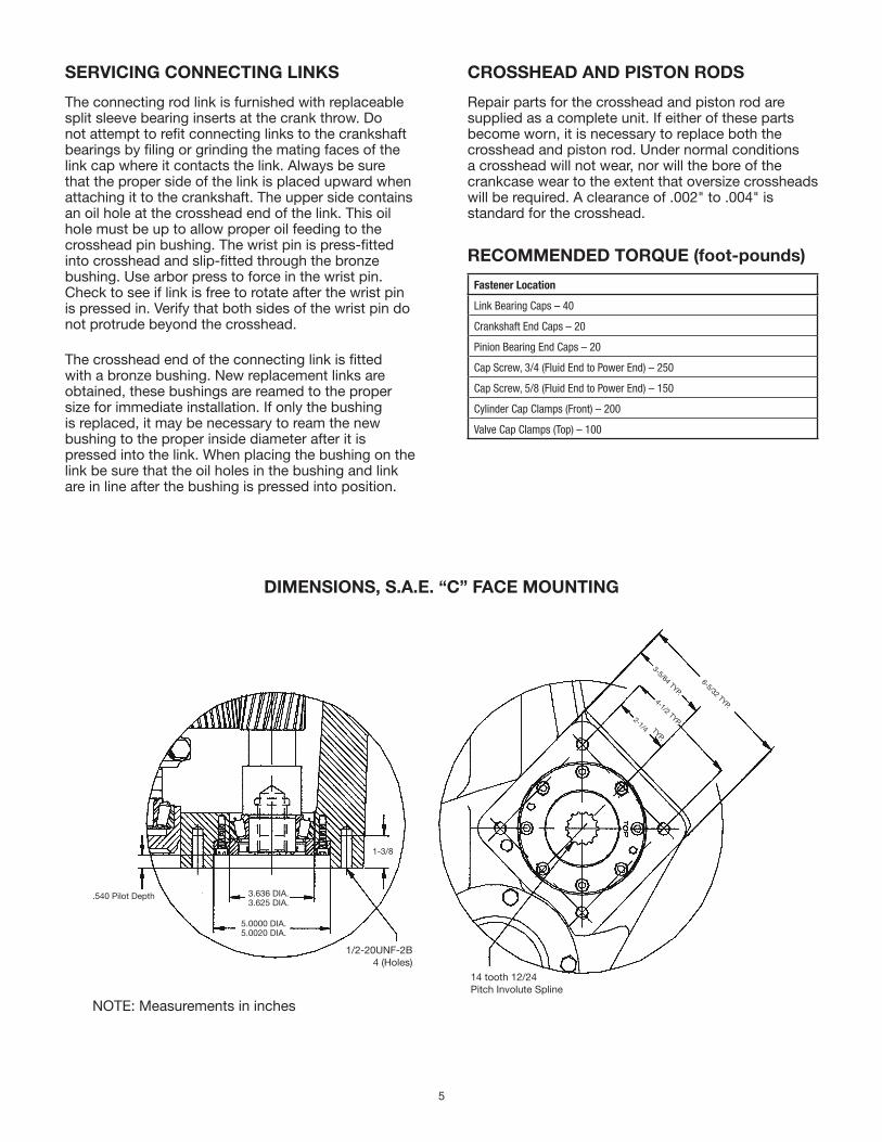
DIMENSIONS, S.A.E. “C” FACE MOUNTING
1/2-20UNF-2B4 (Holes)
14 tooth 12/24Pitch Involute Spline
6-5/32 TYP.
3-5/64 TYP.
TYP.
4-1/2 TYP.2-1/4
1-3/8
3.636 DIA.3.625 DIA.
.540 Pilot Depth
5.0000 DIA.5.0020 DIA.
NOTE: Measurements in inches
6
Explanation of the Service Chart
1. Pump priming is usually not necessary when the pump is installed correctly. However, there are certain conditions which may make it necessary to prime the pump to get the pumping action started. Priming will be required when it is impossible for the piston to displace the air in the pump and replace it with water. This could be caused by a high suction lift, the valves being stuck on the seat or by valves sticking due to extreme corrosion. A pump will not prime readily if someone has tampered with the valve springs causing them to exert undue pressure of the valve plates against the valve seats.
2. A gate valve is sometimes installed in the suction line between a tank or pressure line and the pump sediment chamber. It will shut off the supply source in order to clean the sediment chamber or to perform pump repairs. If this valve is partially or fully closed, it will interfere with the flow of water to the pump suction. This also may cause severe knocking and vibration of the pump because the water cannot flow into the cylinder cavities fast enough.
3. A sediment chamber should be installed in the suction line between the gate valve and the pump suction. The strainers in these sediment chambers are to allow a free flow of liquid to the pump. If the strainers become severely clogged, they will completely stop the flow of liquid to the pump.
4. Any piston pump operating at a high pressure will not perform properly or quietly if a mixture of air and water is allowed to enter the pump suction. A small air leak in the suction line will cause the pump to knock and vibrate excessively by allowing the pump to draw a certain amount of water mixed with air on each stroke of the piston. A large air leak will cause the pump to lose prime after which it cannot be reprimed until the air leak is stopped. Air leaks may occur at the joints of the suction line piping, at the gate valve in the suction line, at the gasket sealing the cap on the sediment chamber, by a crack in the suction wall of the cylinder body, or by air drawing past the packing on the suction stroke if the packing is badly worn.
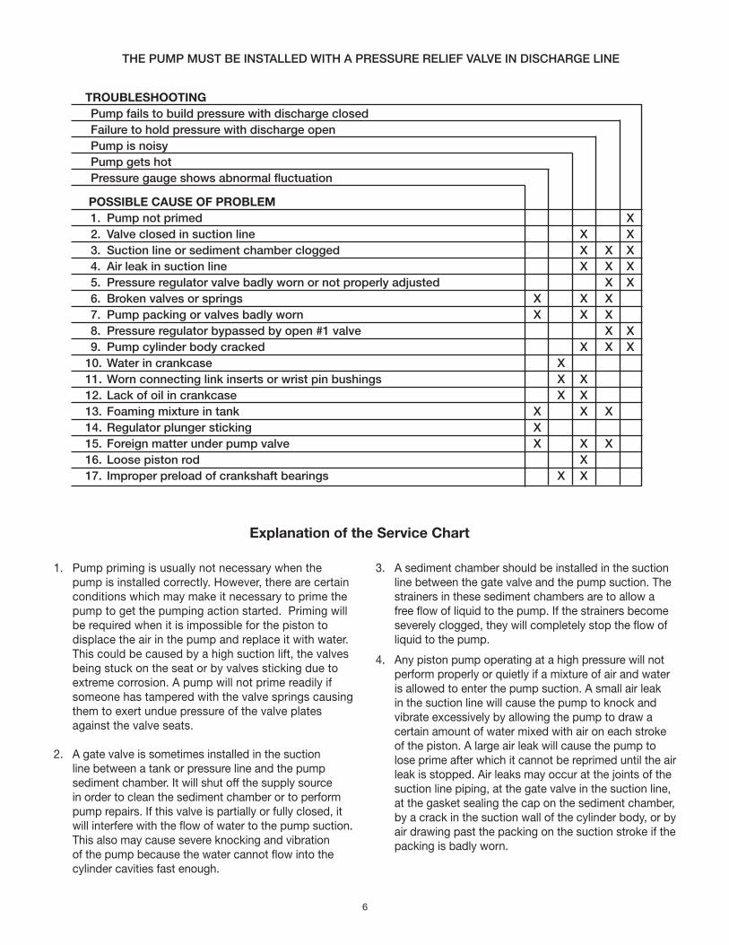
THE PUMP MUST BE INSTALLED WITH A PRESSURE RELIEF VALVE IN DISCHARGE LINE
TROUBLESHOOTING Pump fails to build pressure with discharge closed Failure to hold pressure with discharge open Pump is noisy Pump gets hot Pressure gauge shows abnormal fluctuation
POSSIBLE CAUSE OF PROBLEM 1. Pump not primed X 2. Valve closed in suction line X X 3. Suction line or sediment chamber clogged X X X 4. Air leak in suction line X X X 5. Pressure regulator valve badly worn or not properly adjusted X X 6. Broken valves or springs X X X 7. Pump packing or valves badly worn X X X 8. Pressure regulator bypassed by open #1 valve X X 9. Pump cylinder body cracked X X X10. Water in crankcase X11. Worn connecting link inserts or wrist pin bushings X X12. Lack of oil in crankcase X X13. Foaming mixture in tank X X X14. Regulator plunger sticking X15. Foreign matter under pump valve X X X16. Loose piston rod X17. Improper preload of crankshaft bearings X X
7
5. If the pressure regulator internal bypass valve is worn, it will allow too much of the pump capacity to be bypassed and recirculated back to the tank. By examining the flow from this valve with the discharge turned on, it can be determined whether or not the valve is worn. If a heavy flow continues when the discharge is turned on, it is usually a good indication of a worn valve and should be replaced.
6. A broken pump valve or spring will often prevent one cylinder from functioning properly resulting in a rough pulsing discharge, a knocking sound and a loss of capacity. If not repaired immediately, the rough running pump can cause mechanical damage to itself or other system components.
7. Worn packing, valves or valve seats will cause a severe drop in pump capacity pressure. Worn packing is detected by water leakage and should be replaced immediately. Water getting in the pump crankcase will cause severe corrosion of the bearings and cause rapid wear. Worn valves can be detected by visual examination of each valve assembly. Abrasive liquid will cause wire cuts which begin as a very small groove, but increases rapidly once the valve starts to leak through this groove. If the valves are replaced as soon as they start to show this cutting action, it will prevent the valve seat from becoming cut in a similar manner.
8. If a portion of the pump delivery is allowed to bypass because the #1 control valve is not completely closed, there may not be adequate flow to develop full pressure. This will cause rapid wear in the control valve. Any excess flow should be bypassed only by the pressure regulator.
9. Pump cylinder bodies withstand an extreme amount of shock and pulsation while in operation. If the pump is allowed to freeze, by not being drained, the freezing may crack the cylinder body walls in almost any location. If the crack occurs on the suction valve or cylinder portion of the body, it may allow a small amount of air to enter on the suction stroke and cause noisy operation or a decrease in pumping capacity. If the crack develops in the walls between the cylinder cavities or discharge valve cavity, it may allow the water to flow from one cavity to the adjacent cavity and cause uneven displacement.
10. Water may accumulate in the pump crankcase from two sources; leakage of packing or an accumulation of condensation/moisture inside the crankcase due to changes in weather or the repeated heating and cooling of the pump. Pumps used consistently, running for a considerable period of time to heat the oil and other working parts, will not normally accumulate water by condensation. Replace the packing as soon as it starts to leak.
11. Worn connecting link bearings are caused by unusual or adverse operating conditions and are seriously affected by corrosion if water is present in the crankcase. They will wear out from overheating if the oil is not high quality or clean. Drain, clean and refill with new oil at the specified interval and prior to any storage period. Replace link inserts as soon as any wear is noticed to avoid damage to crankshaft journals.
12. Low oil in the crankcase can quickly cause failure of the pumps power end and result in extensive repairs. Oil level should be checked periodically during normal operation and during all maintenance work.
13. A foaming mixture will sometimes have the same effect as a small air leak in the suction line. This is because various quantities of the foam are drawn through the suction line into the pump disrupting the normal flow of water.
14. Pressure regulators can become sluggish due to the plunger sticking or fitting too tightly in the cylinder. This may happen by an accumulation of chemicals collecting in and around the plunger or from excessive corrosion of the plunger parts. To check this condition, remove and clean the plunger and cover the parts with a waterproof grease before assembling. The pressure regulator may chatter or vibrate excessively due to an unstable operation from nozzling in the high or low capacity range of the regulator. The range should be at least 50% to 90% of pump capacity.
15. If foreign matter becomes lodged between the pump valve and valve seat, a drastic drop in capacity and considerable surge or pulsation will occur in the discharge line. Examine each valve if this occurs.
16. Noisy pump operation may be caused by a loose piston rod in the crosshead. This noise usually has a regular cadence timed with each stroke. If this happens, always replace both the rod and the crosshead.
17. Increased preload to the crankshaft bearings will reduce bearing life, require more power and generate more heat. Insufficient preload may cause a knock, timed with the crankshaft rotation. Check for loose bolts on the crankshaft end caps or adjust shims to obtain proper bearing preload. Worn roller bearings will continue to run but will introduce wear particles into the oil.
8
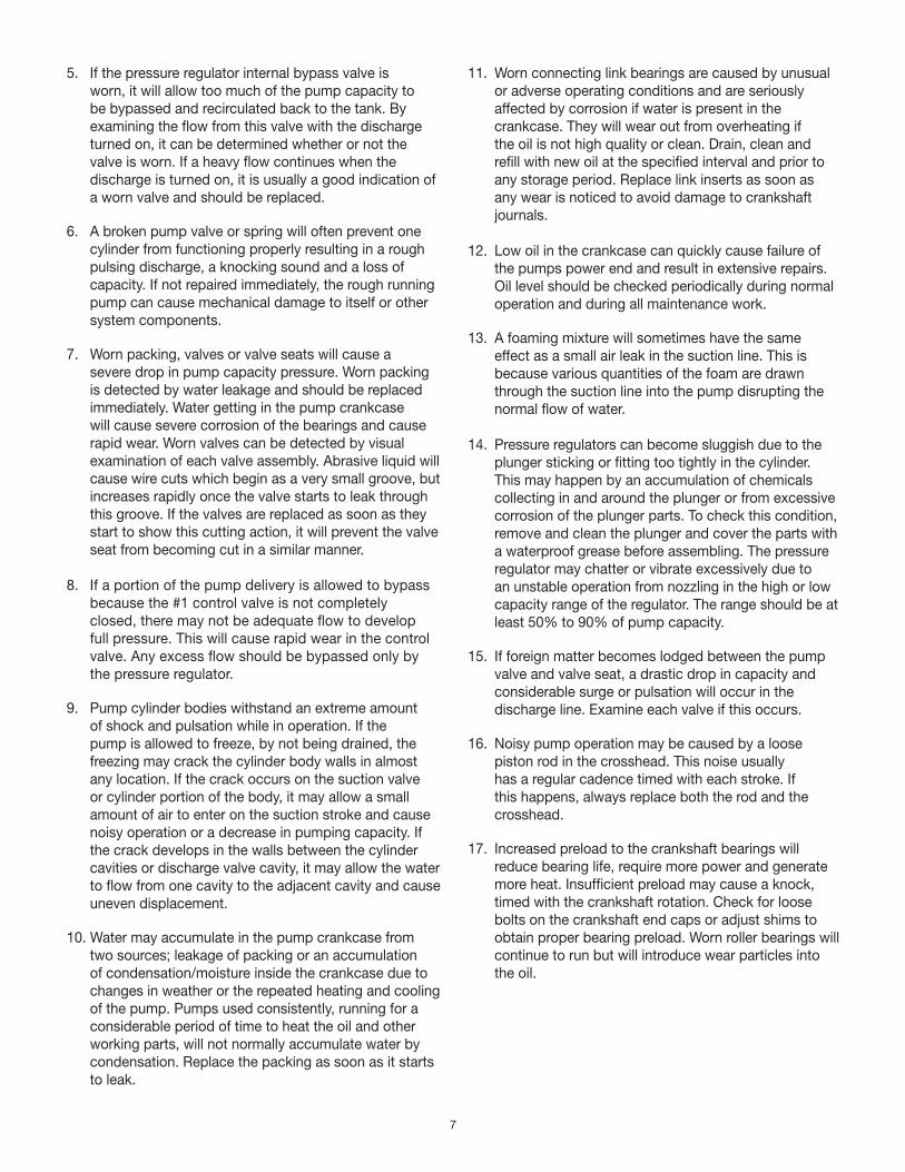
E54-30-H/D, E70-23-H/D, E80-20-H/D, E110-14-H/D
9
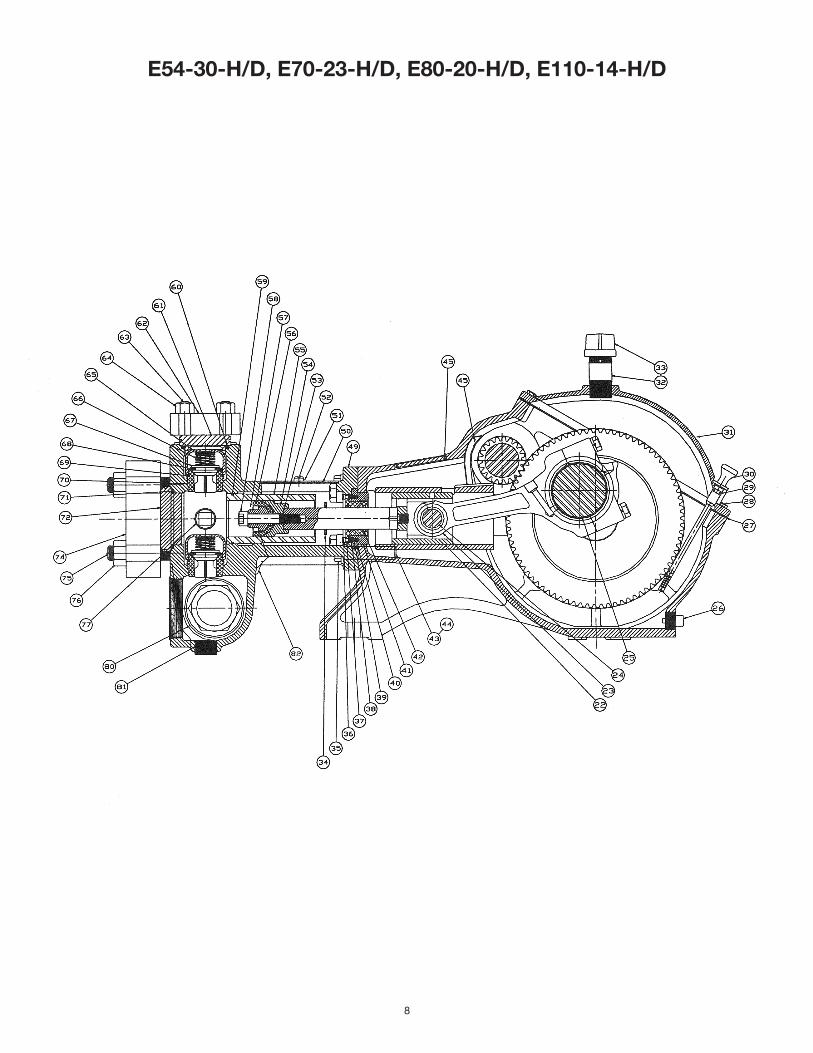
E70-23V-H/D, E75-25-H/D, E80-20V-H/D, E80-25-H/D
47
46
76
75
74
72
71
70
69
68
67
66
65
64
63
62
61
60
59
58
78
79
80
55
92
53
51
52
50
45
45 32
31
30
29
28
27
26
25
24
23
22
44
43
42
41
40
39
38
37
73
48
11
36
35
34
33
49
77
10
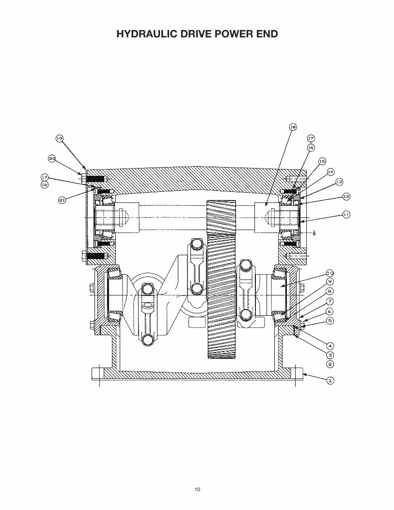
HYDRAULIC DRIVE POWER END
11
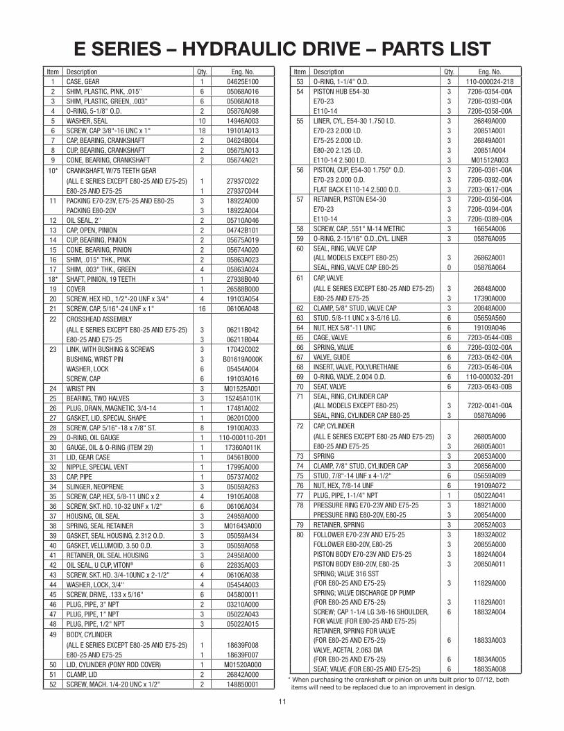
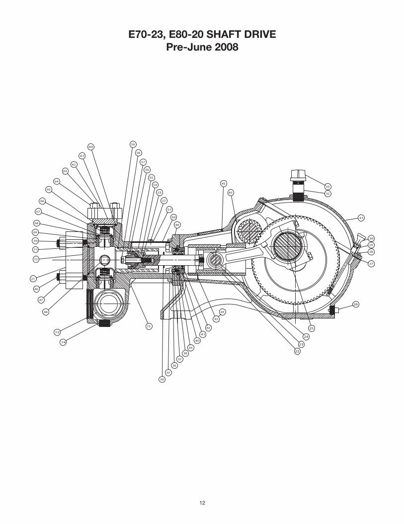
E SERIES – HYDRAULIC DRIVE – PARTS LISTItem Description Qty. Eng. No.
1 CASE, GEAR 1 04625E1002 SHIM, PLASTIC, PINK, .015" 6 05068A0163 SHIM, PLASTIC, GREEN, .003" 6 05068A0184 O-RING, 5-1/8" O.D. 2 05876A0985 WASHER, SEAL 10 14946A0036 SCREW, CAP 3/8"-16 UNC x 1" 18 19101A0137 CAP, BEARING, CRANKSHAFT 2 04624B0048 CUP, BEARING, CRANKSHAFT 2 05675A0139 CONE, BEARING, CRANKSHAFT 2 05674A021
10* CRANKSHAFT, W/75 TEETH GEAR(ALL E SERIES EXCEPT E80-25 AND E75-25) 1 27937C022E80-25 AND E75-25 1 27937C044
11 PACKING E70-23V, E75-25 AND E80-25 3 18922A000PACKING E80-20V 3 18922A004
12 OIL SEAL, 2" 2 05710A04613 CAP, OPEN, PINION 2 04742B10114 CUP, BEARING, PINION 2 05675A01915 CONE, BEARING, PINION 2 05674A02016 SHIM, .015" THK., PINK 2 05863A02317 SHIM, .003" THK., GREEN 4 05863A02418* SHAFT, PINION, 19 TEETH 1 27938B04019 COVER 1 26588B00020 SCREW, HEX HD., 1/2"-20 UNF x 3/4" 4 19103A05421 SCREW, CAP, 5/16"-24 UNF x 1" 16 06106A04822 CROSSHEAD ASSEMBLY
(ALL E SERIES EXCEPT E80-25 AND E75-25) 3 06211B042E80-25 AND E75-25 3 06211B044
23 LINK, WITH BUSHING & SCREWS 3 17042C002BUSHING, WRIST PIN 3 B01619A000KWASHER, LOCK 6 05454A004SCREW, CAP 6 19103A016
24 WRIST PIN 3 M01525A00125 BEARING, TWO HALVES 3 15245A101K26 PLUG, DRAIN, MAGNETIC, 3/4-14 1 17481A00227 GASKET, LID, SPECIAL SHAPE 1 06201C00028 SCREW, CAP 5/16"-18 x 7/8" ST. 8 19100A03329 O-RING, OIL GAUGE 1 110-000110-20130 GAUGE, OIL & O-RING (ITEM 29) 1 17360A011K31 LID, GEAR CASE 1 04561B00032 NIPPLE, SPECIAL VENT 1 17995A00033 CAP, PIPE 1 05737A00234 SLINGER, NEOPRENE 3 05059A26335 SCREW, CAP, HEX, 5/8-11 UNC x 2 4 19105A00836 SCREW, SKT. HD. 10-32 UNF x 1/2" 6 06106A03437 HOUSING, OIL SEAL 3 24959A00038 SPRING, SEAL RETAINER 3 M01643A00039 GASKET, SEAL HOUSING, 2.312 O.D. 3 05059A43440 GASKET, VELLUMOID, 3.50 O.D. 3 05059A05841 RETAINER, OIL SEAL HOUSING 3 24958A00042 OIL SEAL, U CUP, VITON® 6 22835A00343 SCREW, SKT. HD. 3/4-10UNC x 2-1/2" 4 06106A03844 WASHER, LOCK, 3/4" 4 05454A00345 SCREW, DRIVE, .133 x 5/16" 6 04580001146 PLUG, PIPE, 3" NPT 2 03210A00047 PLUG, PIPE, 1" NPT 3 05022A04348 PLUG, PIPE, 1/2" NPT 3 05022A01549 BODY, CYLINDER
(ALL E SERIES EXCEPT E80-25 AND E75-25) 1 18639F008E80-25 AND E75-25 1 18639F007
50 LID, CYLINDER (PONY ROD COVER) 1 M01520A00051 CLAMP, LID 2 26842A00052 SCREW, MACH. 1/4-20 UNC x 1/2" 2 148850001
Item Description Qty. Eng. No.53 O-RING, 1-1/4" O.D. 3 110-000024-21854 PISTON HUB E54-30 3 7206-0354-00A
E70-23 3 7206-0393-00AE110-14 3 7206-0358-00A
55 LINER, CYL. E54-30 1.750 I.D. 3 26849A000E70-23 2.000 I.D. 3 20851A001E75-25 2.000 I.D. 3 26849A001E80-20 2.125 I.D. 3 20851A004E110-14 2.500 I.D. 3 M01512A003
56 PISTON, CUP, E54-30 1.750" O.D. 3 7206-0361-00AE70-23 2.000 O.D. 3 7206-0392-00AFLAT BACK E110-14 2.500 O.D. 3 7203-0617-00A
57 RETAINER, PISTON E54-30 3 7206-0356-00AE70-23 3 7206-0394-00AE110-14 3 7206-0389-00A
58 SCREW, CAP, .551" M-14 METRIC 3 16654A00659 O-RING, 2-15/16" O.D.,CYL. LINER 3 05876A09560 SEAL, RING, VALVE CAP
(ALL MODELS EXCEPT E80-25) 3 26862A001SEAL, RING, VALVE CAP E80-25 0 05876A064
61 CAP, VALVE(ALL E SERIES EXCEPT E80-25 AND E75-25) 3 26848A000E80-25 AND E75-25 3 17390A000
62 CLAMP, 5/8" STUD, VALVE CAP 3 20848A00063 STUD, 5/8-11 UNC x 3-5/16 LG. 6 05659A56064 NUT, HEX 5/8"-11 UNC 6 19109A04665 CAGE, VALVE 6 7203-0544-00B66 SPRING, VALVE 6 7206-0302-00A67 VALVE, GUIDE 6 7203-0542-00A68 INSERT, VALVE, POLYURETHANE 6 7203-0546-00A69 O-RING, VALVE, 2.004 O.D. 6 110-000032-20170 SEAT, VALVE 6 7203-0543-00B71 SEAL, RING, CYLINDER CAP
(ALL MODELS EXCEPT E80-25) 3 7202-0041-00ASEAL, RING, CYLINDER CAP E80-25 3 05876A096
72 CAP, CYLINDER(ALL E SERIES EXCEPT E80-25 AND E75-25) 3 26805A000E80-25 AND E75-25 3 26805A001
73 SPRING 3 20853A00074 CLAMP, 7/8" STUD, CYLINDER CAP 3 20856A00075 STUD, 7/8"-14 UNF x 4-1/2" 6 05659A08976 NUT, HEX, 7/8-14 UNF 6 19109A07277 PLUG, PIPE, 1-1/4" NPT 1 05022A04178 PRESSURE RING E70-23V AND E75-25 3 18921A000
PRESSURE RING E80-20V, E80-25 3 20854A00079 RETAINER, SPRING 3 20852A00380 FOLLOWER E70-23V AND E75-25 3 18932A002
FOLLOWER E80-20V, E80-25 3 20855A000PISTON BODY E70-23V AND E75-25 3 18924A004PISTON BODY E80-20V, E80-25 3 20850A011SPRING; VALVE 316 SST(FOR E80-25 AND E75-25) 3 11829A000SPRING; VALVE DISCHARGE DP PUMP(FOR E80-25 AND E75-25) 3 11829A001SCREW; CAP 1-1/4 LG 3/8-16 SHOULDER, FOR VALVE (FOR E80-25 AND E75-25)
6 18832A004
RETAINER, SPRING FOR VALVE(FOR E80-25 AND E75-25) 6 18833A003VALVE, ACETAL 2.063 DIA (FOR E80-25 AND E75-25) 6 18834A005SEAT; VALVE (FOR E80-25 AND E75-25) 6 18835A008
* When purchasing the crankshaft or pinion on units built prior to 07/12, both items will need to be replaced due to an improvement in design.
12
42
63
73
74
71
47
46
48
21
72
67
70
69
68
66
65
64
75
36
35
34
37
40
39
38
41
54
55
51
49
50
52
53
62
60
61
57
58
59
56
25
22
23
24
44
43
45
45
F
L
26
32
33
31
28
27
29
30
E70-23, E80-20 SHAFT DRIVEPre-June 2008
13
E70-23, E80-20 SHAFT DRIVEPost-June 2008
47
46
76
75
74
72
71
70
69
68
67
66
65
64
63
62
61
60
59
58
78
79
80
55
92
53
51
52
50
45
45 32
31
30
29
28
27
26
25
24
23
22
44
43
42
41
40
39
38
37
73
48
11
36
35
34
33
49
77
14
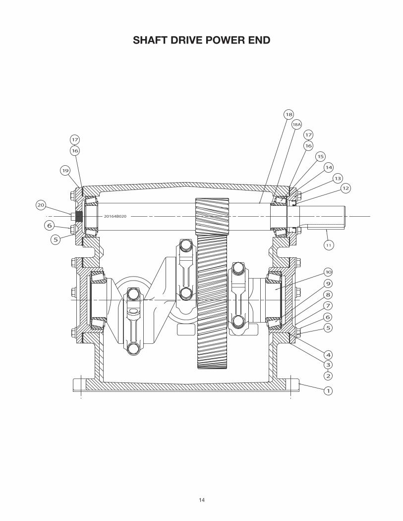
SHAFT DRIVE POWER END
20164B020
20
16
5
6
19
17
10
8
9
1
3
4
5
7
6
2
18A
15
18
16
14
12
13
11
17
15
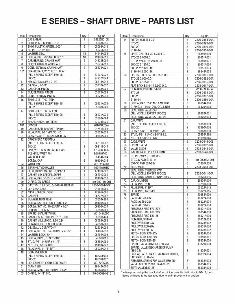
E SERIES – SHAFT DRIVE – PARTS LIST
Item Description Qty. Eng. No.1 CASE, GEAR 1 04625E010E2 SHIM, PLASTIC, PINK, .015" 6 05068A0163 SHIM, PLASTIC, GREEN, .003" 6 05068A0184 O-RING, 5-1/8" O.D. 2 05876A0985 WASHER, SEAL 18 14946A0036 SCREW, CAP 3/8"-16 UNC x 1" 18 19101A0137 CAP, BEARING, CRANKSHAFT 2 04624B0048 CUP, BEARING, CRANKSHAFT 2 05675A0139 CONE, BEARING, CRANKSHAFT 2 05674A021
10* CRANKSHAFT, W/75 TEETH GEAR (ALL E SERIES EXCEPT E80-25) 1 27937C022E80-25 1 27937C044
11 KEY, SQ. 3/8 x 3/8 x 2-1/2 1 05818A04812 OIL SEAL, 1-5/8" 1 05710A01713 CAP, OPEN, PINION 1 04563A00114 CUP, BEARING, PINION 2 05675A00915 CONE, BEARING, PINION 2 05674A01316 SHIM, .015" THK., PINK
(ALL E SERIES EXCEPT E80-25) 4 05231A075E80-25 2 05863A023
17 SHIM, .003" THK., GREEN(ALL E SERIES EXCEPT E80-25) 4 05231A074E80-25 4 05863A024
18* SHAFT, PINION, 19 TEETH 1 27938B02018A SPACER 1 20164B022A19 CAP, CLOSED, BEARING, PINION 1 04741B00120 PLUG, PIPE, 1/2" NPT, SQ. HD. 1 05022A03921 CLAMP, 7/8" STUD, CYLINDER CAP 3 20856A00022 CROSSHEAD ASSEMBLY
(ALL E SERIES EXCEPT E80-25) 3 06211B042E80-25 3 06211B044
23 LINK, WITH BUSHING & SCREWS 3 17042C002KBUSHING, WRIST PIN 3 B01619A001WASHER, LOCK 6 05454A004SCREW, CAP 6 19103A016
24 WRIST PIN 3 M01525A00125 BEARING, TWO HALVES 3 15245A101K26 PLUG, DRAIN, MAGNETIC, 3/4-14 1 17481A00227 GASKET, LID, SPECIAL SHAPE 1 06201C00028 SCREW, CAP 5/16"-18 x 7/8" ST. 8 19100A03329 O-RING, OIL GAUGE 1 110-000110-20130 DIPSTICK, OIL LEVEL & O-RING (ITEM 29) 1 7206-0094-00K31 LID, GEAR CASE 1 04561B00032 NIPPLE, SPECIAL VENT 1 17995A00033 CAP, PIPE 1 05737A00234 SLINGER, NEOPRENE 3 05059A26335 SCREW, CAP, HEX, 5/8-11 UNC x 2 4 19105A00836 SCREW, SKT. HD. 10-32 UNF x 1/2" 6 06106A03437 HOUSING, OIL SEAL 3 24959A00038 SPRING, SEAL RETAINER 3 M01643A00039 GASKET, SEAL HOUSING, 2.312 O.D. 3 05059A43440 GASKET, VELLUMOID, 3.50 O.D. 3 05059A05841 RETAINER, OIL SEAL HOUSING 3 24958A00042 OIL SEAL, U CUP, VITON® 6 22835A00343 SCREW, SKT. HD. 3/4-10 UNC x 2-1/2" 4 06106A03844 WASHER, LOCK, 3/4" 4 05454A00345 SCREW, DRIVE, .133 x 5/16" 6 04580001146 STUD, 7/8"-14 UNF x 4-1/2" 6 05659A08947 NUT, HEX, 7/8-14 UNF 6 19109A07248 PLUG, PIPE, 1-1/4" NPT 1 05022A04149 BODY, CYLINDER
(ALL E SERIES EXCEPT E80-25) 1 18639F008E80-25 1 18639F007
50 LID, CYLINDER (PONY ROD COVER) 1 M01520A00051 CLAMP, LID 2 26842A00052 SCREW, MACH. 1/4-20 UNC x 1/2" 2 14885000153 O-RING, 1-1/4" O.D. 3 110-000024-218
Item Description Qty. Eng. No.54 PISTON HUB E54-30 3 7206-0354-00A
E70-23 3 7206-0393-00AE80-20 3 7206-0396-00AE110-14 3 7206-0358-00A
55 LINER, CYL. E54-30 1.750 I.D. 3 26849A000E70-23 2.000 I.D. 3 20851A001E70-23V/E80-25 2.000 I.D. 3 26849A001E80-20 2.125 I.D. 3 20851A004E80-20V 2.125 I.D. 3 20851A004E110-14 2.500 I.D. 3 26849A003
56 PISTON, CUP, E54-30 1.750" O.D. 3 7206-0361-00AE70-23 2.000 O.D. 3 7206-0392-00AE80-20 2.125 O.D. 3 7206-0395-00AFLAT BACK E110-14 2.500 O.D. 3 7203-0617-00A
57 RETAINER, PISTON E54-30 3 7206-0356-0AE70-23 3 7206-0394-00AE80-20 3 7206-0397-00AE110-14 3 7206-0359-00A
58 SCREW, CAP, .551" M-14 METRIC 3 16654A00659 O-RING, 2-15/16" O.D.,CYL. LINER 3 05876A09560 SEAL, RING, VALVE CAP
(ALL MODELS EXCEPT E80-25) 3 26862A001SEAL, RING, VALVE CAP E80-25 3 05876A064
61 CAP, VALVE(ALL E SERIES EXCEPT E80-25) 3 26848A000E80-25 3 17390A000
62 CLAMP, 5/8" STUD, VALVE CAP 3 20848A00063 STUD, 5/8-11 UNC x 3-5/16 LG. 6 05659A56064 NUT, HEX 5/8"-11 UNC 6 19109A04665 CAGE, VALVE 6 7203-0544-00B66 SPRING, VALVE 6 7206-0302-00A67 VALVE, GUIDE 6 7203-0542-00A68 INSERT, VALVE, POLYURETHANE 6 7203-0546-00A69 O-RING, VALVE, 2.004 O.D.
E70.23V AND E110-14 6 110-000032-201E54-30 AND E80-20V 6 05876A236
70 SEAT, VALVE 6 7203-0543-00B71 SEAL, RING, CYLINDER CAP
(ALL MODELS EXCEPT E80-25) 3 7202-0041-00ASEAL, RING, CYLINDER CAP E80-25 3 05876A096
72 CAP, CYLINDER 3 26805A00073 PLUG, PIPE, 3" NPT 2 03210A00074 PLUG, PIPE, 1" NPT 3 05022A04375 PLUG, PIPE, 1/2" NPT 3 05022A01576 SPRING 3 20853A00077 PACKING E70-23V 3 18922A000
PACKING E80-20V 3 18922A004PACKING E80-25 3 18922A000PRESSURE RING E70-23V 3 18921A000PRESSURE RING E80-20V 3 20854A000PRESSURE RING E80-25 3 18921A000RETAINER, SPRING 3 20852A003FOLLOWER E70-23V 3 18923A002FOLLOWER E80-20V 3 20855A000FOLLOWER E80-25 3 18923A002PISTON BODY E70-23V 3 18924A004PISTON BODY E80-20V 3 20850A011PISTON BODY E80-25 3 18924A004SPRING; VALVE 316 SST (E80-25) 3 11829A000SPRING; VALVE DISCHARGE DP PUMP (E80-25) 3 11829A001SCREW; CAP 1-1/4 LG 3/8-16 SHOULDER,FOR VALVE (E80-25)
6 18832A004
RETAINER, SPRING FOR VALVE (E80-25) 6 18833A003VALVE, ACETAL 2.063 DIA (E80-25) 6 18834A005SEAT; VALVE (E80-25) 6 18835A008
* When purchasing the crankshaft or pinion on units built prior to 07/12, both items will need to be replaced due to an improvement in design.
1101 MYERS PARKWAY ASHLAND, OHIO, USA 44805 419-289-1144
WWW.FEMYERS.COM
Warranty Rev. 12/13
STANDARD LIMITED WARRANTYCENTRIFUGAL & RECIPROCATING PUMPS
Pentair Myers® warrants its products against defects in material and workmanship for a period of 12 months from the date of shipment from Pentair Myers or 18 months from the manufacturing date, whichever occurs first – provided that such products are used in compliance with the requirements of the Pentair Myers catalog and technical manuals.
During the warranty period and subject to the conditions set forth, Pentair Myers, at its discretion, will repair or replace to the original user, the parts that prove defective in materials and workmanship. Pentair Myers reserves the right to change or improve its products or any portions thereof without being obligated to provide such a change or improvement for prior sold and/or shipped units.
Seals, piston cups, packing, plungers, liners and valves used for handling clear, fresh, nonaerated water at a temperature not exceeding 120ºF are warranted for ninety days from date of shipment. All other applications are subject to a thirty day warranty. Accessories such as motors, engines and auxiliary equipment are warranted by the respective manufacturer and are excluded in this standard warranty. Under no circumstance will Pentair Myers be responsible for the cost of field labor, travel expenses, rented equipment, removal/reinstallation costs or freight expenses to and from the factory or an authorized Pentair Myers service facility.
This limited warranty will not apply: (a) to defects or malfunctions resulting from failure to properly install, operate or maintain the unit in accordance with the printed instructions provided; (b) to failures resulting from abuse, accident or negligence; (c) to normal maintenance services and parts used in connection with such service; (d) to units that are not installed in accordance with applicable local codes, ordinances and good trade practices; (e) if the unit is moved from its original installation location; (f) if unit is used for purposes other than for what it is designed and manufactured; (g) to any unit that has been repaired or altered by anyone other than Pentair Myers or an authorized Pentair Myers service provider; (h) to any unit that has been repaired using non factory specified/OEM parts.
Warranty Exclusions: PENTAIR MYERS MAKES NO EXPRESS OR IMPLIED WARRANTIES THAT EXTEND BEYOND THE DESCRIPTION ON THE FACE HEREOF. PENTAIR MYERS SPECIFICALLY DISCLAIMS THE IMPLIED WARRANTIES OF MERCHANTABILITY AND FITNESS FOR ANY PARTICULAR PURPOSE.
Liability Limitation: IN NO EVENT SHALL PENTAIR MYERS BE LIABLE OR RESPONSIBLE FOR CONSEQUENTIAL, INCIDENTAL OR SPECIAL DAMAGES RESULTING FROM OR RELATED IN ANY MANNER TO ANY PENTAIR MYERS PRODUCT OR PARTS THEREOF. PERSONAL INJURY AND/OR PROPERTY DAMAGE MAY RESULT FROM IMPROPER INSTALLATION. PENTAIR MYERS DISCLAIMS ALL LIABILITY, INCLUDING LIABILITY UNDER THIS WARRANTY, FOR IMPROPER INSTALLATION. PENTAIR MYERS RECOMMENDS INSTALLATION BY PROFESSIONALS.
Some states do not permit some or all of the above warranty limitations or the exclusion or limitation of incidental or consequential damages and therefore such limitations may not apply to you. No warranties or representations at any time made by any representatives of Pentair Myers shall vary or expand the provision hereof.


![Untitled-9 []Crosshead Assembly (r.h.) 690-700E—218 Crosshead Screw Combination Lever Assembly 610—8005-540 Steam Chest Assembly S20:3-3 . 1 610-8005-601 Frame and Wheel Assembly](https://img.pdfslide.net/doc/110x75/5e6da9490ffe761883346650/untitled-9-crosshead-assembly-rh-690-700ea218-crosshead-screw-combination.jpg)