Embed Size (px)
Citation preview

Control Valves - SMARTLINK® MRV 10 - 30.7 - 1E - m - 1/11
SMARTLINK® MRVIntelligent MICRO-RATIO® Valve Series
Precise and repeatable flow control optimizes fuel efficiency, enables accurate temperature control and lowers burner emissions.
SMARTLINK® MRV is an electronic parallel positioning system for air/fuel ratio control; for use in industrial applications providing a high degree of precision, repeatability and durability.
Synchronous control of up to four valves with conventional signal from the user’s process controller.
Direct coupled valve and actuator assembly includes weatherproof housing with integrated position feedback and heavy duty planetary gearheads for reliable, long life operation.
Compact, robust design mounts in any orientation.
Each SMARTLINK® Valve is adjustable to 0.1 degrees accuracy.
UL and CE approved electronics and software for air-fuel ratio control
Stores a 22 point user-customized profile for each valve.
Factory Mutual (FM) approved as non-incendive for Hazardous Locations Class I, Division 2, Groups A, B, C and D, T4 Temperature code; NEMA 4X standard actuator
Maintenance-free operation; no lubrication required. No valve packing to adjust.
Electronic passcode protection eliminates valve profile tampering.
Simple set-up; no PC required.
Standby, purge and light off positions can be defined independent of valve profiles.
w w w . m a x o n c o r p . c o mcombustion systems for industryMaxon reserves the right to alter specifications and data without prior notice. © 2011 Copyright Maxon Corporation. All rights reserved.
Control Valves - SMARTLINK® MRV 10 - 30.7 - 2E - m - 1/11
Product Description
The MAXON SMARTLINK® MICRO-RATIO® Valve (MRV) is an industrial parallel positioning system for combustion applications providing a high
degree of precision, repeatability, tamper resistance, and durability. In addition, SMARTLINK® MRV interfaces with all burner management and flame safety systems, simplifying retrofit applications. The system is simple to set-up and does not require a personal computer in the field for commissioning.
SMARTLINK® MRV includes 1, 2, 3, or 4 Valve Actuators directly coupled to flow control valves, and a Control Interface unit which serves as a commissioning interface and “gateway” between the Valve Actuators and the user’s process controller, PLC, or distributed control system (DCS).
The SMARTLINK® Valve Actuator design is an industrial, factory-calibrated assembly. It incorporates a precision, planetary gear-head with integrated position feedback and a stepper motor for continuous duty control of various valves. Each valve actuator is powered by 24VDC and includes a digital position control loop and a digital interface that ensures reliable operation even in electrically noisy environments. The small footprint, weatherproof enclosure and Class I, Division 2 approvals, and superior position control performance make this product a high performance, cheaper alternative to pneumatic equipment.
The SMARTLINK® MRV Control Interface is a DIN rail-mounted digital hub that electronically “links” and synchronizes valve movement for precision air/fuel ratio control. Front-mounted switches and indicators are provided for displaying alarms, system configuration, and valve characterization. The Control Interface also provides a precision 4-20 mA firing rate feedback signal. Optional equipment includes MAXON Relay Input and Output Interfaces, a User Display, universal power supply, factory-wired panel assemblies, and several NEMA 4X enclosures.
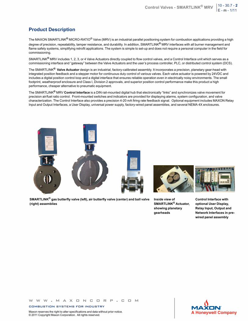
SMARTLINK® gas butterfly valve (left), air butterfly valve (center) and ball valve (right) assemblies
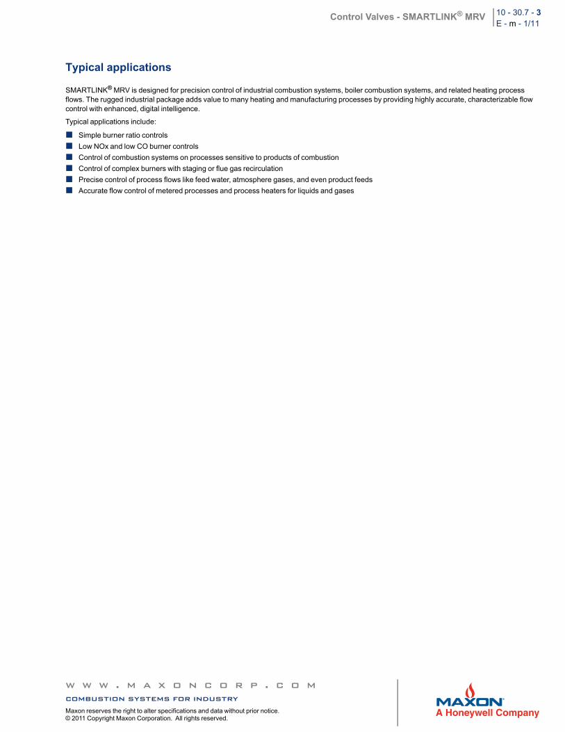
Inside view of SMARTLINK® Actuator, showing planetary gearheads
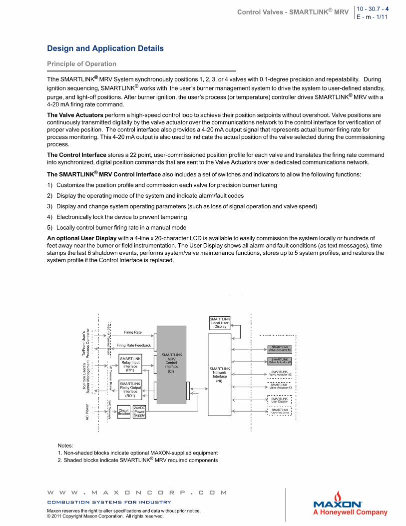
Control Interface with optional User Display, Relay Input, Output and Network Interfaces in pre-wired panel assembly
w w w . m a x o n c o r p . c o mcombustion systems for industryMaxon reserves the right to alter specifications and data without prior notice. © 2011 Copyright Maxon Corporation. All rights reserved.
Control Valves - SMARTLINK® MRV 10 - 30.7 - 3E - m - 1/11
Typical applications
SMARTLINK® MRV is designed for precision control of industrial combustion systems, boiler combustion systems, and related heating process flows. The rugged industrial package adds value to many heating and manufacturing processes by providing highly accurate, characterizable flow control with enhanced, digital intelligence.
Typical applications include:
Simple burner ratio controls
Low NOx and low CO burner controls
Control of combustion systems on processes sensitive to products of combustion
Control of complex burners with staging or flue gas recirculation
Precise control of process flows like feed water, atmosphere gases, and even product feeds
Accurate flow control of metered processes and process heaters for liquids and gases
w w w . m a x o n c o r p . c o mcombustion systems for industryMaxon reserves the right to alter specifications and data without prior notice. © 2011 Copyright Maxon Corporation. All rights reserved.
Control Valves - SMARTLINK® MRV 10 - 30.7 - 4E - m - 1/11
Design and Application Details
Principle of Operation
Tthe SMARTLINK® MRV System synchronously positions 1, 2, 3, or 4 valves with 0.1-degree precision and repeatability. During
ignition sequencing, SMARTLINK® works with the user’s burner management system to drive the system to user-defined standby,
purge, and light-off positions. After burner ignition, the user’s process (or temperature) controller drives SMARTLINK® MRV with a 4-20 mA firing rate command.
The Valve Actuators perform a high-speed control loop to achieve their position setpoints without overshoot. Valve positions are continuously transmitted digitally by the valve actuator over the communications network to the control interface for verification of proper valve position. The control interface also provides a 4-20 mA output signal that represents actual burner firing rate for process monitoring. This 4-20 mA output is also used to indicate the actual position of the valve selected during the commissioning process.
The Control Interface stores a 22 point, user-commissioned position profile for each valve and translates the firing rate command into synchronized, digital position commands that are sent to the Valve Actuators over a dedicated communications network.
The SMARTLINK® MRV Control Interface also includes a set of switches and indicators to allow the following functions:
1) Customize the position profile and commission each valve for precision burner tuning
2) Display the operating mode of the system and indicate alarm/fault codes
3) Display and change system operating parameters (such as loss of signal operation and valve speed)
4) Electronically lock the device to prevent tampering
5) Locally control burner firing rate in a manual mode
An optional User Display with a 4-line x 20-character LCD is available to easily commission the system locally or hundreds of feet away near the burner or field instrumentation. The User Display shows all alarm and fault conditions (as text messages), time stamps the last 6 shutdown events, performs system/valve maintenance functions, stores up to 5 system profiles, and restores the system profile if the Control Interface is replaced.
AC
Po
wer
To/F
rom
Use
rs’s
B
urn
er
Ma
nag
em
ent
To/F
rom
Use
r’s
Pro
cess
Co
ntr
olle
r
Firing Rate
Firing Rate Feedback
SMARTLINKRelay InputInterface
(RI1)
SMARTLINKRelay Output
Interface(RO1)
CircuitBreaker
24VDCPowerSupply
SMARTLINKLocal User
Display
SMARTLINKMRV
ControlInterface
(CI)SMARTLINK
NetworkInterface
(NI)
SMARTLINKValve Actuator #0
SMARTLINKValve Actuator #1
SMARTLINKValve Actuator #2
SMARTLINKValve Actuator #3
SMARTLINKUser Display
SMARTLINKFuture Field Device
4-2
0 m
A Te
rmin
al B
lock
I/O Te
rmin
al B
locks
VA
C Te
rmin
als
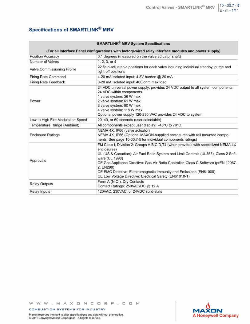
Notes:1. Non-shaded blocks indicate optional MAXON-supplied equipment2. Shaded blocks indicate SMARTLINK® MRV required components
w w w . m a x o n c o r p . c o mcombustion systems for industryMaxon reserves the right to alter specifications and data without prior notice. © 2011 Copyright Maxon Corporation. All rights reserved.
Control Valves - SMARTLINK® MRV 10 - 30.7 - 5E - m - 1/11
Specifications of SMARTLINK® MRV
SMARTLINK® MRV System Specifications
(For all Interface Panel configurations with factory-wired relay interface modules and power supply)
Position Accuracy 0.1 degrees (measured on the valve actuator shaft)
Number of Valves 1, 2, 3, or 4
Valve Commissioning Profile22 field-adjustable positions for each valve including individual standby, purge and light-off positions
Firing Rate Command 4-20 mA isolated input; 4.8V burden @ 20 mA
Firing Rate Feedback 0-20 mA isolated input; 400 ohm max load
Power
24 VDC universal power supply; provides 24 VDC output to all system components24 VDC within components1 valve system: 36 W max2 valve system: 61 W max3 valve system: 90 W max4 valve system: 118 W maxOptional power supply 120-230 VAC provides 24 VDC to system
Low to High Fire Modulation Speed 20, 40, or 60 seconds (user selectable)
Temperature Range (Ambient) All components except user display: -40°C to 70°C
Enclosure RatingsNEMA 4X, IP66 (valve actuator)NEMA 4X, IP66 (Optional MAXON-supplied enclosures with rail mounted compo-nents. See page 10-30.7-5 for individual components ratings)
Approvals
FM Class I, Division 2: Groups A,B,C,D,T4 (when provided with specialized NEMA 4X enclosures)UL (US & Canadian): Air Fuel Ratio System and Limit Controls (UL353), Class 2 Soft-ware (UL 1998)CE Gas Appliance Directive: Gas-Air Ratio Controller, Class C Software (prEN 12067-2, EN298)CE EMC Directive: Electromagnetic Immunity and Emissions (EN61000)CE Low Voltage Directive: Electrical Safety (EN61010-1)
Relay OutputsForm A (N.O.), Dry ContactsContact Ratings: 250VAC/DC @ 12 A
Relay Inputs 120VAC, 230VAC, or 24VDC solid-state
w w w . m a x o n c o r p . c o mcombustion systems for industryMaxon reserves the right to alter specifications and data without prior notice. © 2011 Copyright Maxon Corporation. All rights reserved.
Control Valves - SMARTLINK® MRV 10 - 30.7 - 6E - m - 1/11
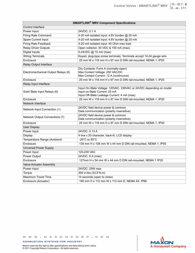
SMARTLINK® MRV Component Specifications
Control Interface
Power Input 24VDC, 0.1 A
Firing Rate Command 4-20 mA isolated input; 4.8V burden @ 20 mA
Spare Current Input 4-20 mA isolated input; 4.8V burden @ 20 mA
Firing Rate Feedback 4-20 mA isolated input: 40 Ohm max load
Relay Driver Outputs Open collector, 30 VDC & 100 mA (max)
Digital Inputs 5-24VDC @ 10 mA (max)
Wiring Terminals Keyed, plug-type screw terminals; Terminals accept 14-24 gauge wire
Enclosure 25 mm W x 118 mm H x 97 mm D DIN rail-mounted, NEMA 1, IP20
Relay Output Interface
Electromechanical Output Relays (6)Dry Contacts: Form A (normally-open)Max Contact Voltage: 250 VAC/DCMax Contact Current: 12 A (continuous)
Enclosure 25 mm W x 118 mm H x 97 mm D DIN rail-mounted, NEMA 1, IP20
Relay Input Interface
Solid State Input Relays (6)Input On-State Voltage: 120VAC, 230VAC or 24VDC depending on modelInput on-State Current: 25 mAInput Off-State Leakage Current: 4 mA (max)
Enclosure 25 mm W x 118 mm H x 97 mm D DIN rail-mounted, NEMA 1, IP20
Network Interface
Network Input Connection (1)24VDC field device power & commonData communication (polarity insensitive)
Network Output Connections (7)24VDC field device power & commonData communication (polarity insensitive)
Enclosure 25 mm W x 118 mm H x 97 mm D DIN rail-mounted, NEMA 1, IP20
User Display
Power Input 24VDC, 0.13 A
Display 4 line x 20 character, back-lit, LCD display
Temperature Range (Ambient) -29°C to 50°C
Enclosure 139 mm H x 108 mm W x 44 mm D DIN rail-mounted, NEMA 1, IP50
Universal Power Supply
Power Input 120-230 VAC
Power Output 24VDC, 6 A (max)
Enclosure 127mm H x 54 mm W x 44 mm D DIN rail-mounted, NEMA 1 IP20
Valve-Actuator Assembly
Power Input 24VDC, 25W max
Torque 300 in-lbs (33.9 N.m)
Maximum Travel Time 14 seconds (open to close)
Enclosure (Actuator) 195 mm H x 112 mm W x 112 mm D, NEMA 4X, IP66
w w w . m a x o n c o r p . c o mcombustion systems for industryMaxon reserves the right to alter specifications and data without prior notice. © 2011 Copyright Maxon Corporation. All rights reserved.
Control Valves - SMARTLINK® MRV 10 - 30.7 - 7E - m - 1/11
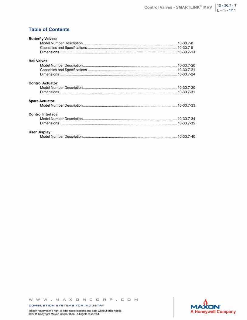
Table of Contents
Butterfly Valves:Model Number Description............................................................................................. 10-30.7-8Capacities and Specifications ........................................................................................ 10-30.7-9Dimensions .................................................................................................................... 10-30.7-13
Ball Valves:Model Number Description............................................................................................. 10-30.7-20Capacities and Specifications ........................................................................................ 10-30.7-21Dimensions .................................................................................................................... 10-30.7-24
Control Actuator:Model Number Description............................................................................................. 10-30.7-30Dimensions .................................................................................................................... 10-30.7-31
Spare Actuator:Model Number Description............................................................................................. 10-30.7-33
Control Interface:Model Number Description............................................................................................. 10-30.7-34Dimensions .................................................................................................................... 10-30.7-35
User Display:Model Number Description............................................................................................. 10-30.7-40
w w w . m a x o n c o r p . c o mcombustion systems for industryMaxon reserves the right to alter specifications and data without prior notice. © 2011 Copyright Maxon Corporation. All rights reserved.
Control Valves - SMARTLINK® MRV 10 - 30.7 - 8E - m - 1/11
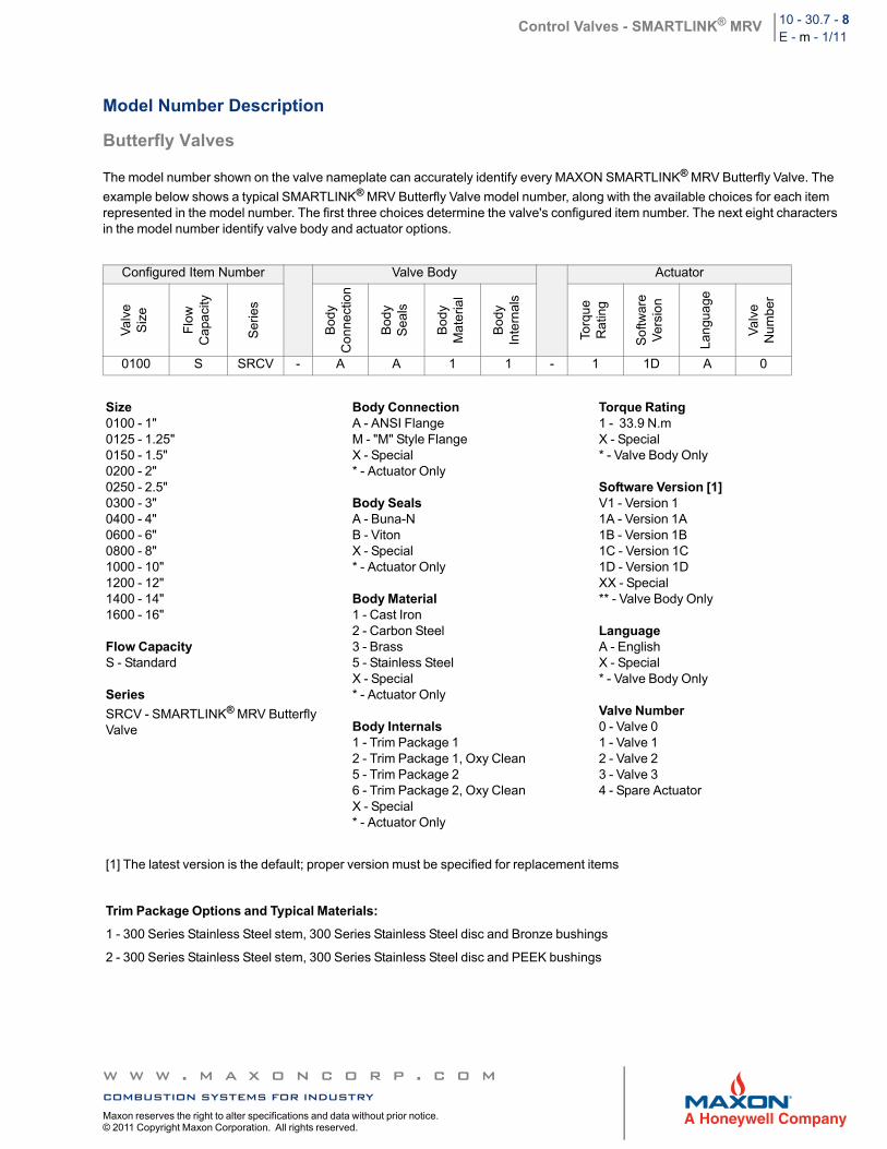
Model Number Description
Butterfly Valves
The model number shown on the valve nameplate can accurately identify every MAXON SMARTLINK® MRV Butterfly Valve. The
example below shows a typical SMARTLINK® MRV Butterfly Valve model number, along with the available choices for each item represented in the model number. The first three choices determine the valve's configured item number. The next eight characters in the model number identify valve body and actuator options.
Configured Item Number Valve Body Actuator
Val
ve
Siz
e
Flo
wC
apa
city
Ser
ies
Bod
yC
onn
ectio
n
Bod
y S
eals
Bod
yM
ate
rial
Bod
yIn
tern
als
Torq
ue
Rat
ing
So
ftwar
eV
ersi
on
Lan
gua
ge
Val
veN
umbe
r
0100 S SRCV - A A 1 1 - 1 1D A 0
Size0100 - 1"0125 - 1.25"0150 - 1.5"0200 - 2"0250 - 2.5"0300 - 3"0400 - 4"0600 - 6"0800 - 8"1000 - 10"1200 - 12"1400 - 14"1600 - 16"
Flow CapacityS - Standard
Series
SRCV - SMARTLINK® MRV Butterfly Valve
Body ConnectionA - ANSI FlangeM - "M" Style FlangeX - Special* - Actuator Only
Body SealsA - Buna-NB - VitonX - Special* - Actuator Only
Body Material1 - Cast Iron2 - Carbon Steel3 - Brass5 - Stainless SteelX - Special* - Actuator Only
Body Internals1 - Trim Package 12 - Trim Package 1, Oxy Clean5 - Trim Package 26 - Trim Package 2, Oxy CleanX - Special* - Actuator Only
Torque Rating1 - 33.9 N.mX - Special* - Valve Body Only
Software Version [1]V1 - Version 11A - Version 1A1B - Version 1B1C - Version 1C1D - Version 1DXX - Special** - Valve Body Only
LanguageA - EnglishX - Special* - Valve Body Only
Valve Number0 - Valve 01 - Valve 12 - Valve 23 - Valve 34 - Spare Actuator
[1] The latest version is the default; proper version must be specified for replacement items
Trim Package Options and Typical Materials:
1 - 300 Series Stainless Steel stem, 300 Series Stainless Steel disc and Bronze bushings
2 - 300 Series Stainless Steel stem, 300 Series Stainless Steel disc and PEEK bushings
w w w . m a x o n c o r p . c o mcombustion systems for industryMaxon reserves the right to alter specifications and data without prior notice. © 2011 Copyright Maxon Corporation. All rights reserved.
Control Valves - SMARTLINK® MRV 10 - 30.7 - 9E - m - 1/11
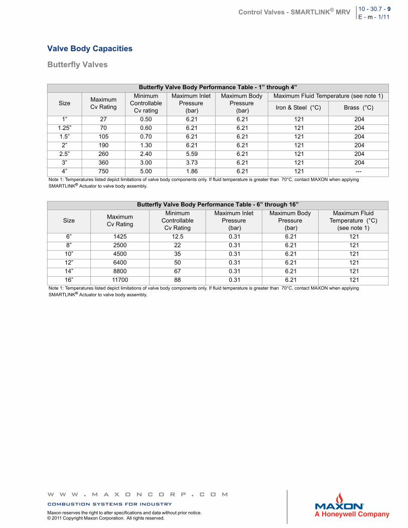
Valve Body Capacities
Butterfly Valves
Butterfly Valve Body Performance Table - 1” through 4”
SizeMaximumCv Rating
Minimum Controllable
Cv rating
Maximum InletPressure
(bar)
Maximum BodyPressure
(bar)
Maximum Fluid Temperature (see note 1)
Iron & Steel (°C) Brass (°C)
1” 27 0.50 6.21 6.21 121 204
1.25” 70 0.60 6.21 6.21 121 204
1.5” 105 0.70 6.21 6.21 121 204
2” 190 1.30 6.21 6.21 121 204
2.5” 260 2.40 5.59 6.21 121 204
3” 360 3.00 3.73 6.21 121 204
4” 750 5.00 1.86 6.21 121 ---Note 1: Temperatures listed depict limitations of valve body components only. If fluid temperature is greater than 70°C, contact MAXON when applying
SMARTLINK® Actuator to valve body assembly.
Butterfly Valve Body Performance Table - 6” through 16”
SizeMaximumCv Rating
Minimum ControllableCv Rating
Maximum InletPressure
(bar)
Maximum BodyPressure
(bar)
Maximum FluidTemperature (°C)
(see note 1)
6” 1425 12.5 0.31 6.21 121
8” 2500 22 0.31 6.21 121
10” 4500 35 0.31 6.21 121
12” 6400 50 0.31 6.21 121
14” 8800 67 0.31 6.21 121
16” 11700 88 0.31 6.21 121Note 1: Temperatures listed depict limitations of valve body components only. If fluid temperature is greater than 70°C, contact MAXON when applying
SMARTLINK® Actuator to valve body assembly.
w w w . m a x o n c o r p . c o mcombustion systems for industryMaxon reserves the right to alter specifications and data without prior notice. © 2011 Copyright Maxon Corporation. All rights reserved.
Control Valves - SMARTLINK® MRV 10 - 30.7 - 10E - m - 1/11
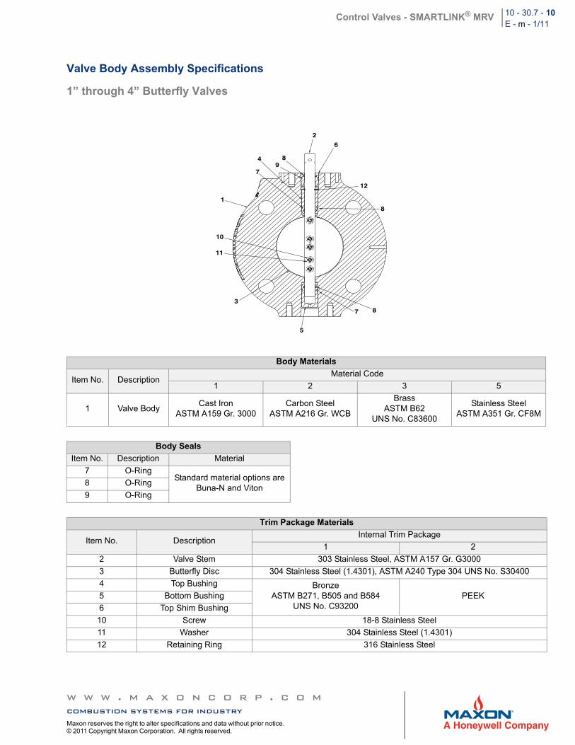
Valve Body Assembly Specifications
1” through 4” Butterfly Valves
Body Materials
Item No. DescriptionMaterial Code
1 2 3 5
1 Valve BodyCast Iron
ASTM A159 Gr. 3000Carbon Steel
ASTM A216 Gr. WCB
BrassASTM B62
UNS No. C83600
Stainless SteelASTM A351 Gr. CF8M
Body Seals
Item No. Description Material
7 O-RingStandard material options are
Buna-N and Viton8 O-Ring
9 O-Ring
Trim Package Materials
Item No. DescriptionInternal Trim Package
1 2
2 Valve Stem 303 Stainless Steel, ASTM A157 Gr. G3000
3 Butterfly Disc 304 Stainless Steel (1.4301), ASTM A240 Type 304 UNS No. S30400
4 Top Bushing BronzeASTM B271, B505 and B584
UNS No. C93200PEEK5 Bottom Bushing
6 Top Shim Bushing
10 Screw 18-8 Stainless Steel
11 Washer 304 Stainless Steel (1.4301)
12 Retaining Ring 316 Stainless Steel
4 89
2
6
1
12
10
11
3
5
7
87
8
w w w . m a x o n c o r p . c o mcombustion systems for industryMaxon reserves the right to alter specifications and data without prior notice. © 2011 Copyright Maxon Corporation. All rights reserved.
Control Valves - SMARTLINK® MRV 10 - 30.7 - 11E - m - 1/11
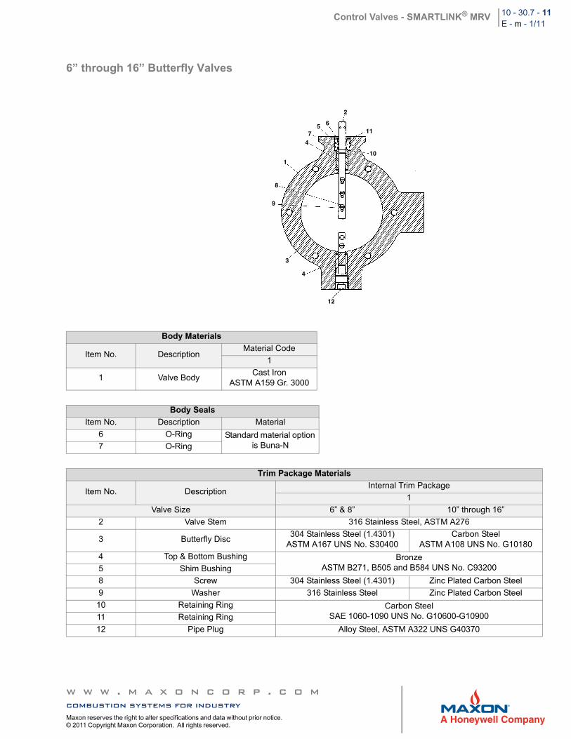
6” through 16” Butterfly Valves
Body Materials
Item No. DescriptionMaterial Code
1
1 Valve BodyCast Iron
ASTM A159 Gr. 3000
Body Seals
Item No. Description Material
6 O-Ring Standard material option is Buna-N7 O-Ring
Trim Package Materials
Item No. DescriptionInternal Trim Package
1
Valve Size 6” & 8” 10” through 16”
2 Valve Stem 316 Stainless Steel, ASTM A276
3 Butterfly Disc304 Stainless Steel (1.4301)
ASTM A167 UNS No. S30400Carbon Steel
ASTM A108 UNS No. G10180
4 Top & Bottom Bushing BronzeASTM B271, B505 and B584 UNS No. C932005 Shim Bushing
8 Screw 304 Stainless Steel (1.4301) Zinc Plated Carbon Steel
9 Washer 316 Stainless Steel Zinc Plated Carbon Steel
10 Retaining Ring Carbon SteelSAE 1060-1090 UNS No. G10600-G1090011 Retaining Ring
12 Pipe Plug Alloy Steel, ASTM A322 UNS G40370
2
657
1
4
8
9
11
10
3
4
12
w w w . m a x o n c o r p . c o mcombustion systems for industryMaxon reserves the right to alter specifications and data without prior notice. © 2011 Copyright Maxon Corporation. All rights reserved.
Control Valves - SMARTLINK® MRV 10 - 30.7 - 12E - m - 1/11
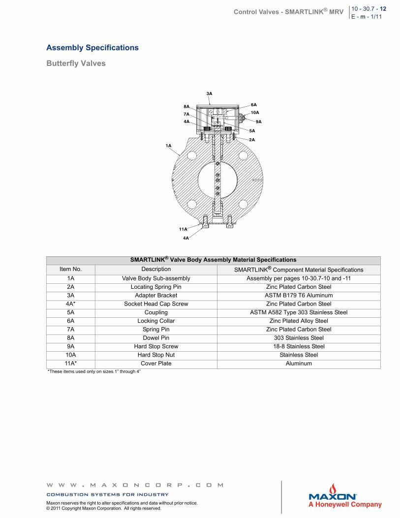
Assembly Specifications
Butterfly Valves
SMARTLINK® Valve Body Assembly Material Specifications
Item No. Description SMARTLINK® Component Material Specifications
1A Valve Body Sub-assembly Assembly per pages 10-30.7-10 and -11
2A Locating Spring Pin Zinc Plated Carbon Steel
3A Adapter Bracket ASTM B179 T6 Aluminum
4A* Socket Head Cap Screw Zinc Plated Carbon Steel
5A Coupling ASTM A582 Type 303 Stainless Steel
6A Locking Collar Zinc Plated Alloy Steel
7A Spring Pin Zinc Plated Carbon Steel
8A Dowel Pin 303 Stainless Steel
9A Hard Stop Screw 18-8 Stainless Steel
10A Hard Stop Nut Stainless Steel
11A* Cover Plate Aluminum*These items used only on sizes 1” through 4”
3A
8A
7A
4A
6A
10A
9A
5A
2A
11A
4A
1A
w w w . m a x o n c o r p . c o mcombustion systems for industryMaxon reserves the right to alter specifications and data without prior notice. © 2011 Copyright Maxon Corporation. All rights reserved.
Control Valves - SMARTLINK® MRV 10 - 30.7 - 13E - m - 1/11
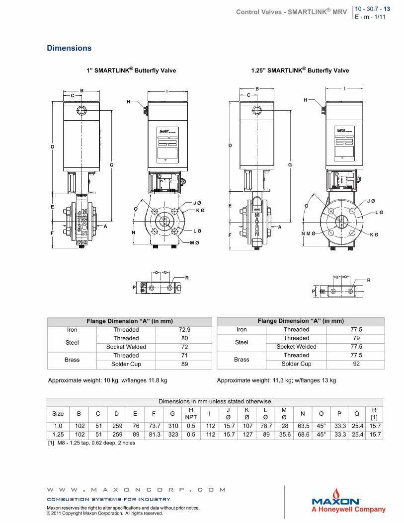
Dimensions
1” SMARTLINK® Butterfly Valve 1.25” SMARTLINK® Butterfly Valve
Approximate weight: 10 kg; w/flanges 11.8 kg Approximate weight: 11.3 kg; w/flanges 13 kg
Dimensions in mm unless stated otherwise
Size B C D E F GH
NPTI
JØ
KØ
LØ
MØ
N O P QR[1]
1.0 102 51 259 76 73.7 310 0.5 112 15.7 107 78.7 28 63.5 45° 33.3 25.4 15.7
1.25 102 51 259 89 81.3 323 0.5 112 15.7 127 89 35.6 68.6 45° 33.3 25.4 15.7[1] M8 - 1.25 tap, 0.62 deep, 2 holes
B
D
C
E
A
G
F
I
N
J Ø
K Ø
L Ø
M Ø
R
P
Q Q
H
O
BC
D
E
F
A
G
H
I
O
N M Ø
J Ø
L Ø
K Ø
P
QQR
Flange Dimension “A” (in mm)
Iron Threaded 72.9
SteelThreaded 80
Socket Welded 72
BrassThreaded 71
Solder Cup 89
Flange Dimension “A” (in mm)
Iron Threaded 77.5
SteelThreaded 79
Socket Welded 77.5
BrassThreaded 77.5
Solder Cup 92
w w w . m a x o n c o r p . c o mcombustion systems for industryMaxon reserves the right to alter specifications and data without prior notice. © 2011 Copyright Maxon Corporation. All rights reserved.
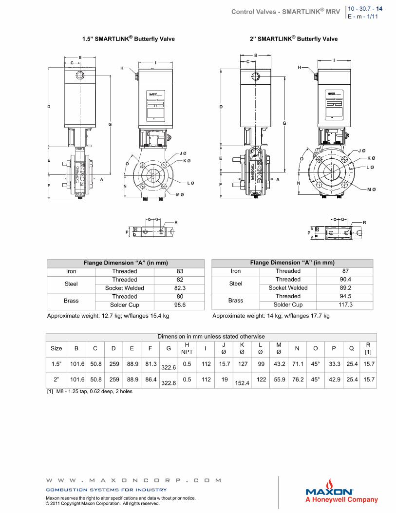
Control Valves - SMARTLINK® MRV 10 - 30.7 - 14E - m - 1/11
1.5” SMARTLINK® Butterfly Valve 2” SMARTLINK® Butterfly Valve
Approximate weight: 12.7 kg; w/flanges 15.4 kg Approximate weight: 14 kg; w/flanges 17.7 kg
Dimension in mm unless stated otherwise
Size B C D E F GH
NPTI
JØ
KØ
LØ
MØ
N O P QR[1]
1.5” 101.6 50.8 259 88.9 81.3
322.60.5 112 15.7 127 99 43.2 71.1 45° 33.3 25.4 15.7
2” 101.6 50.8 259 88.9 86.4
322.60.5 112 19
152.4
122 55.9 76.2 45° 42.9 25.4 15.7
[1] M8 - 1.25 tap, 0.62 deep, 2 holes
C
D
G
E
F
A
O
N
J Ø
K Ø
L Ø
M Ø
P
RQ Q
BI
H
BC
D
G
E
FA
O
N
J Ø
K Ø
L Ø
M Ø
P
RQQ
1"
I
H
Flange Dimension “A” (in mm)
Iron Threaded 83
SteelThreaded 82
Socket Welded 82.3
BrassThreaded 80
Solder Cup 98.6
Flange Dimension “A” (in mm)
Iron Threaded 87
SteelThreaded 90.4
Socket Welded 89.2
BrassThreaded 94.5
Solder Cup 117.3
w w w . m a x o n c o r p . c o mcombustion systems for industryMaxon reserves the right to alter specifications and data without prior notice. © 2011 Copyright Maxon Corporation. All rights reserved.
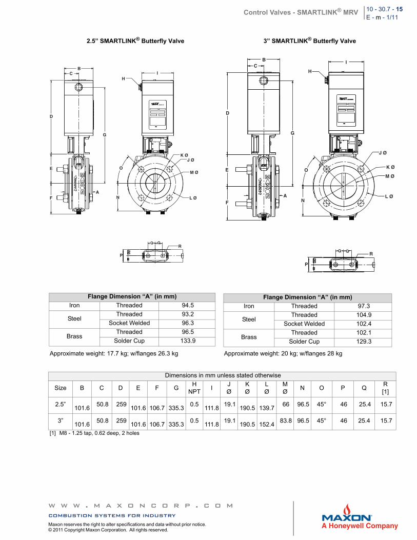
Control Valves - SMARTLINK® MRV 10 - 30.7 - 15E - m - 1/11
2.5” SMARTLINK® Butterfly Valve 3” SMARTLINK® Butterfly Valve
Approximate weight: 17.7 kg; w/flanges 26.3 kg Approximate weight: 20 kg; w/flanges 28 kg
Dimensions in mm unless stated otherwise
Size B C D E F GH
NPTI
JØ
KØ
LØ
MØ
N O P QR[1]
2.5”
101.6 50.8 259
101.6
106.7
335.3
0.5
111.8 19.1
190.5
139.7
66 96.5 45° 46 25.4 15.7
3”
101.6 50.8 259
101.6
106.7
335.3
0.5
111.8 19.1
190.5
152.4
83.8 96.5 45° 46 25.4 15.7
[1] M8 - 1.25 tap, 0.62 deep, 2 holes
A
BC
D
G
IH
E
F
O
N
K ØJ Ø
M Ø
L Ø
P
RQ Q
BC
D
G
E
FA
O
N
J Ø
K Ø
M Ø
L Ø
P
RQ Q
I
H
Flange Dimension “A” (in mm)
Iron Threaded 94.5
SteelThreaded 93.2
Socket Welded 96.3
BrassThreaded 96.5
Solder Cup 133.9
Flange Dimension “A” (in mm)
Iron Threaded 97.3
SteelThreaded 104.9
Socket Welded 102.4
BrassThreaded 102.1
Solder Cup 129.3
w w w . m a x o n c o r p . c o mcombustion systems for industryMaxon reserves the right to alter specifications and data without prior notice. © 2011 Copyright Maxon Corporation. All rights reserved.
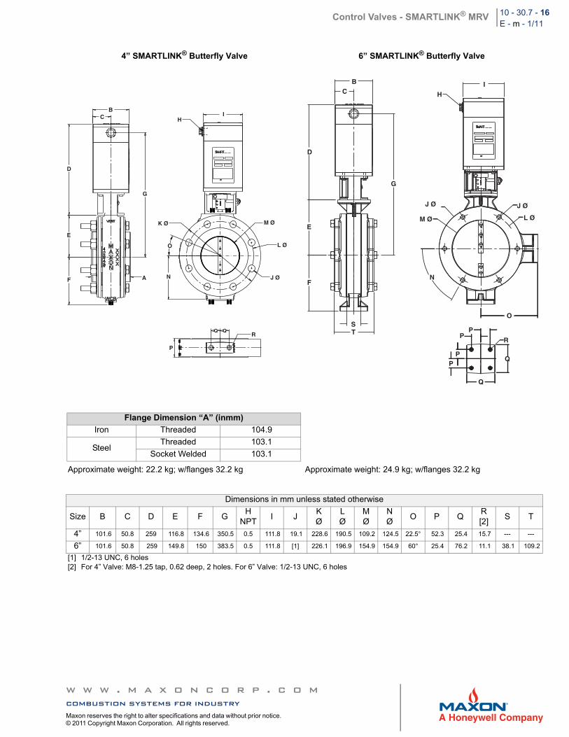
Control Valves - SMARTLINK® MRV 10 - 30.7 - 16E - m - 1/11
4” SMARTLINK® Butterfly Valve 6” SMARTLINK® Butterfly Valve
Approximate weight: 22.2 kg; w/flanges 32.2 kg Approximate weight: 24.9 kg; w/flanges 32.2 kg
Dimensions in mm unless stated otherwise
Size B C D E F GH
NPTI J
KØ
LØ
MØ
NØ
O P QR[2]
S T
4” 101.6 50.8 259 116.8 134.6 350.5 0.5 111.8 19.1 228.6 190.5 109.2 124.5 22.5° 52.3 25.4 15.7 --- ---
6” 101.6 50.8 259 149.8 150 383.5 0.5 111.8 [1] 226.1 196.9 154.9 154.9 60° 25.4 76.2 11.1 38.1 109.2
[1] 1/2-13 UNC, 6 holes[2] For 4” Valve: M8-1.25 tap, 0.62 deep, 2 holes. For 6” Valve: 1/2-13 UNC, 6 holes
BC
D
G
HI
E
F A
K Ø
O
N
M Ø
L Ø
J Ø
P
RQ Q
BC
D
G
H
I
E
F
ST
J Ø
M Ø
J Ø
L Ø
N
O
PP
PP
R
Q
Q
Flange Dimension “A” (inmm)
Iron Threaded 104.9
SteelThreaded 103.1
Socket Welded 103.1
w w w . m a x o n c o r p . c o mcombustion systems for industryMaxon reserves the right to alter specifications and data without prior notice. © 2011 Copyright Maxon Corporation. All rights reserved.
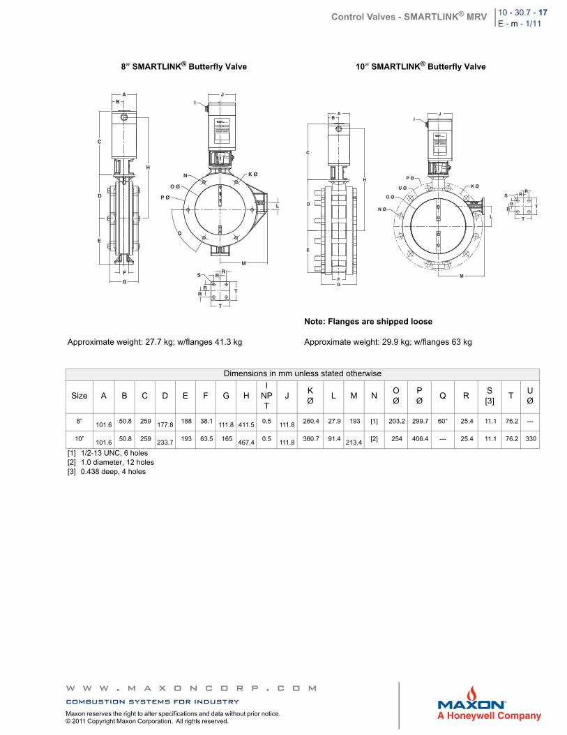
Control Valves - SMARTLINK® MRV 10 - 30.7 - 17E - m - 1/11
8” SMARTLINK® Butterfly Valve 10” SMARTLINK® Butterfly Valve
Approximate weight: 27.7 kg; w/flanges 41.3 kg
Note: Flanges are shipped loose
Approximate weight: 29.9 kg; w/flanges 63 kg
Dimensions in mm unless stated otherwise
Size A B C D E F G HI
NPT
JKØ
L M NOØ
PØ
Q RS[3]
TUØ
8”
101.6 50.8 259
177.8
188 38.1
111.8
411.50.5
111.8
260.4 27.9 193 [1] 203.2 299.7 60° 25.4 11.1 76.2 ---
10”
101.6 50.8 259
233.7
193 63.5 165
467.40.5
111.8
360.7 91.4
213.4[2] 254 406.4 --- 25.4 11.1 76.2 330
[1] 1/2-13 UNC, 6 holes[2] 1.0 diameter, 12 holes[3] 0.438 deep, 4 holes
AB
C
D
H
E
F
G
I
J
K Ø
L
N
O Ø
P Ø
Q
M
S
T
T
RR
RR
JI
AB
C
H
D
E
FG
P Ø
U Ø
O Ø
N Ø
K Ø
L
M
SR
R
RR T
T
w w w . m a x o n c o r p . c o mcombustion systems for industryMaxon reserves the right to alter specifications and data without prior notice. © 2011 Copyright Maxon Corporation. All rights reserved.
Control Valves - SMARTLINK® MRV 10 - 30.7 - 18E - m - 1/11
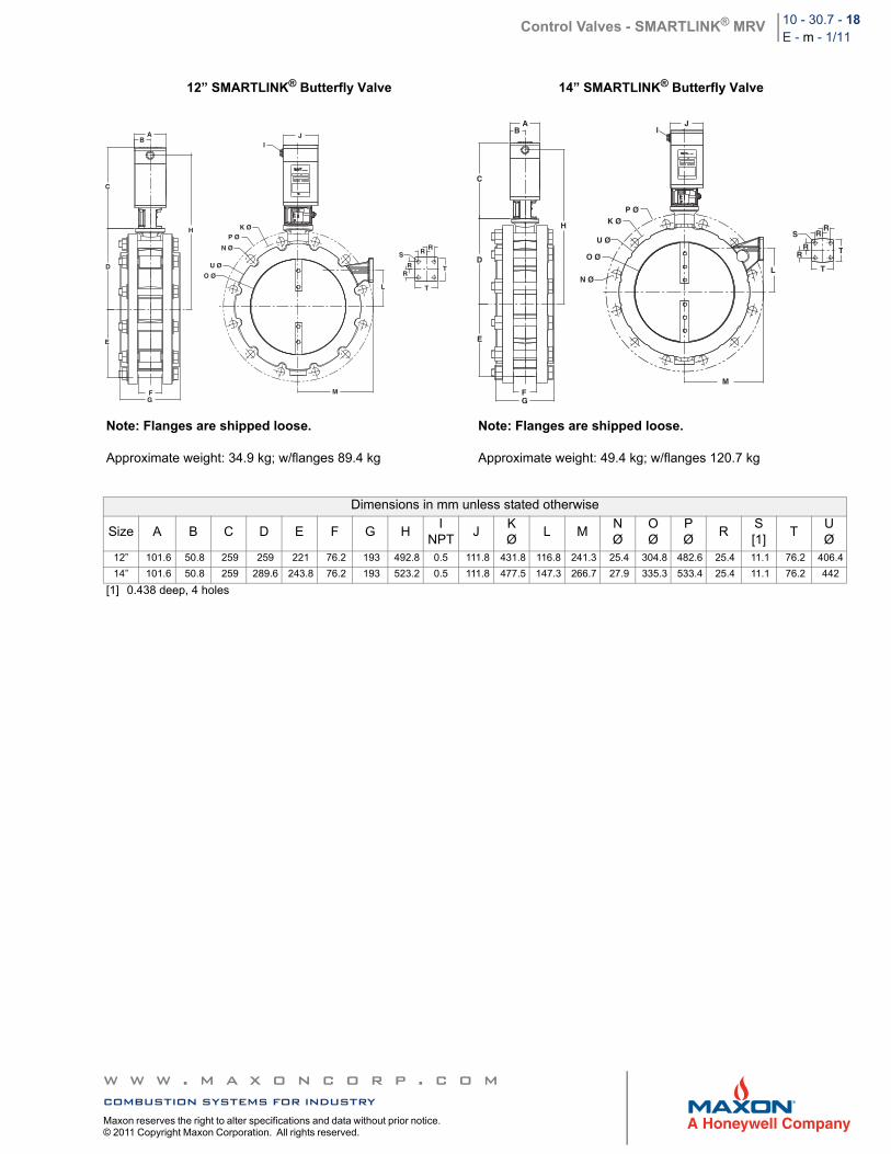
12” SMARTLINK® Butterfly Valve 14” SMARTLINK® Butterfly Valve
Note: Flanges are shipped loose.
Approximate weight: 34.9 kg; w/flanges 89.4 kg
Note: Flanges are shipped loose.
Approximate weight: 49.4 kg; w/flanges 120.7 kg
Dimensions in mm unless stated otherwise
Size A B C D E F G HI
NPTJ
KØ
L MNØ
OØ
PØ
RS[1]
TUØ
12” 101.6 50.8 259 259 221 76.2 193 492.8 0.5 111.8 431.8 116.8 241.3 25.4 304.8 482.6 25.4 11.1 76.2 406.4
14” 101.6 50.8 259 289.6 243.8 76.2 193 523.2 0.5 111.8 477.5 147.3 266.7 27.9 335.3 533.4 25.4 11.1 76.2 442
[1] 0.438 deep, 4 holes
JI
AB
C
D
H
E
FG
K ØP Ø
N Ø
U Ø
O Ø
L
M
SR
R
RR
T
T
2
AB
C
D
H
E
FG
IJ
P ØK Ø
U Ø
O Ø
N Ø
M
L
SR
R
RR
T
T
w w w . m a x o n c o r p . c o mcombustion systems for industryMaxon reserves the right to alter specifications and data without prior notice. © 2011 Copyright Maxon Corporation. All rights reserved.
Control Valves - SMARTLINK® MRV 10 - 30.7 - 19E - m - 1/11
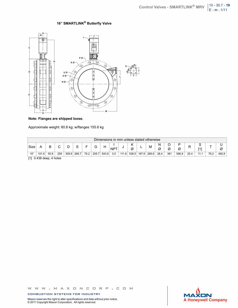
16” SMARTLINK® Butterfly Valve
Note: Flanges are shipped loose.
Approximate weight: 60.8 kg; w/flanges 155.6 kg
Dimensions in mm unless stated otherwise
Size A B C D E F G HI
NPTJ
KØ
L MNØ
OØ
PØ
RS[1]
TUØ
16” 101.6 50.8 259 309.9 266.7 76.2 205.7 543.6 0.5 111.8 538.5 167.6 289.6 28.4 381 596.9 25.4 11.1 76.2 492.8
[1] 0.438 deep, 4 holes
JI
AB
C
D
H
E
FG
P Ø
K Ø
U Ø
O Ø
N Ø
M
L
S RR
RR
T
T
w w w . m a x o n c o r p . c o mcombustion systems for industryMaxon reserves the right to alter specifications and data without prior notice. © 2011 Copyright Maxon Corporation. All rights reserved.
Control Valves - SMARTLINK® MRV 10 - 30.7 - 20E - m - 1/11
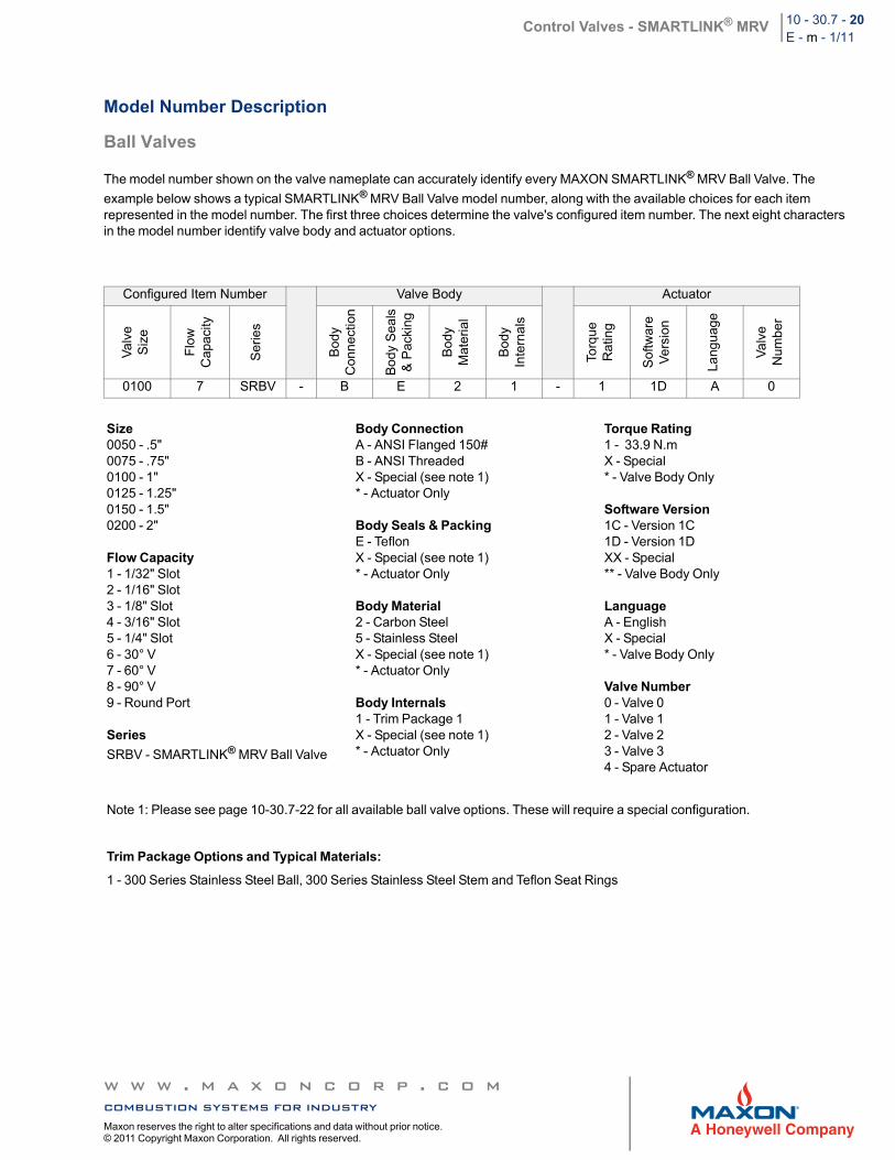
Model Number Description
Ball Valves
The model number shown on the valve nameplate can accurately identify every MAXON SMARTLINK® MRV Ball Valve. The
example below shows a typical SMARTLINK® MRV Ball Valve model number, along with the available choices for each item represented in the model number. The first three choices determine the valve's configured item number. The next eight characters in the model number identify valve body and actuator options.
Configured Item Number Valve Body Actuator
Va
lve
Siz
e
Flo
wC
apac
ity
Ser
ies
Bod
yC
onn
ectio
n
Bo
dy S
eal
s&
Pac
king
Bod
yM
ater
ial
Bod
yIn
tern
als
Torq
ueR
atin
g
Sof
twar
eV
ers
ion
Lang
uag
e
Va
lve
Num
ber
0100 7 SRBV - B E 2 1 - 1 1D A 0
Size0050 - .5"0075 - .75"0100 - 1"0125 - 1.25"0150 - 1.5"0200 - 2"
Flow Capacity1 - 1/32" Slot2 - 1/16" Slot3 - 1/8" Slot4 - 3/16" Slot5 - 1/4" Slot6 - 30° V7 - 60° V8 - 90° V9 - Round Port
Series
SRBV - SMARTLINK® MRV Ball Valve
Body ConnectionA - ANSI Flanged 150#B - ANSI ThreadedX - Special (see note 1)* - Actuator Only
Body Seals & PackingE - TeflonX - Special (see note 1)* - Actuator Only
Body Material2 - Carbon Steel5 - Stainless SteelX - Special (see note 1)* - Actuator Only
Body Internals1 - Trim Package 1X - Special (see note 1)* - Actuator Only
Torque Rating1 - 33.9 N.mX - Special* - Valve Body Only
Software Version1C - Version 1C1D - Version 1DXX - Special** - Valve Body Only
LanguageA - EnglishX - Special* - Valve Body Only
Valve Number0 - Valve 01 - Valve 12 - Valve 23 - Valve 34 - Spare Actuator
Note 1: Please see page 10-30.7-22 for all available ball valve options. These will require a special configuration.
Trim Package Options and Typical Materials:
1 - 300 Series Stainless Steel Ball, 300 Series Stainless Steel Stem and Teflon Seat Rings
w w w . m a x o n c o r p . c o mcombustion systems for industryMaxon reserves the right to alter specifications and data without prior notice. © 2011 Copyright Maxon Corporation. All rights reserved.
Control Valves - SMARTLINK® MRV 10 - 30.7 - 21E - m - 1/11
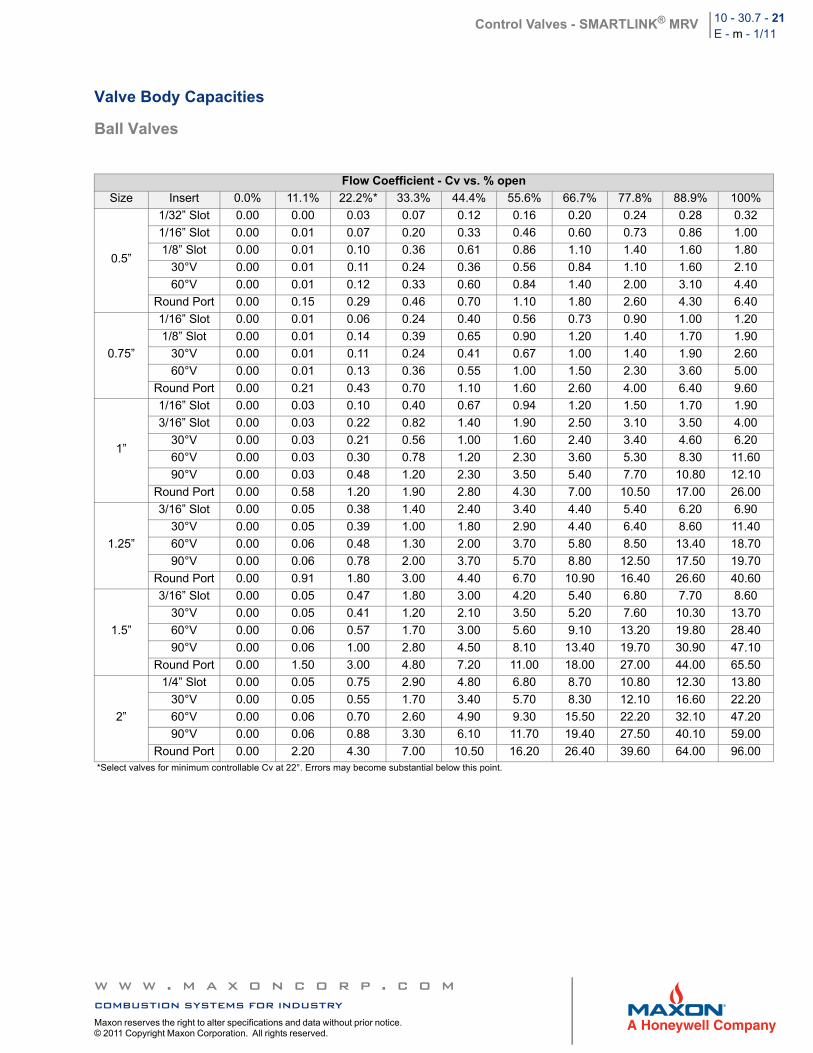
Valve Body Capacities
Ball Valves
Flow Coefficient - Cv vs. % open
Size Insert 0.0% 11.1% 22.2%* 33.3% 44.4% 55.6% 66.7% 77.8% 88.9% 100%
0.5”
1/32” Slot 0.00 0.00 0.03 0.07 0.12 0.16 0.20 0.24 0.28 0.32
1/16” Slot 0.00 0.01 0.07 0.20 0.33 0.46 0.60 0.73 0.86 1.00
1/8” Slot 0.00 0.01 0.10 0.36 0.61 0.86 1.10 1.40 1.60 1.80
30°V 0.00 0.01 0.11 0.24 0.36 0.56 0.84 1.10 1.60 2.10
60°V 0.00 0.01 0.12 0.33 0.60 0.84 1.40 2.00 3.10 4.40
Round Port 0.00 0.15 0.29 0.46 0.70 1.10 1.80 2.60 4.30 6.40
0.75”
1/16” Slot 0.00 0.01 0.06 0.24 0.40 0.56 0.73 0.90 1.00 1.20
1/8” Slot 0.00 0.01 0.14 0.39 0.65 0.90 1.20 1.40 1.70 1.90
30°V 0.00 0.01 0.11 0.24 0.41 0.67 1.00 1.40 1.90 2.60
60°V 0.00 0.01 0.13 0.36 0.55 1.00 1.50 2.30 3.60 5.00
Round Port 0.00 0.21 0.43 0.70 1.10 1.60 2.60 4.00 6.40 9.60
1”
1/16” Slot 0.00 0.03 0.10 0.40 0.67 0.94 1.20 1.50 1.70 1.90
3/16” Slot 0.00 0.03 0.22 0.82 1.40 1.90 2.50 3.10 3.50 4.00
30°V 0.00 0.03 0.21 0.56 1.00 1.60 2.40 3.40 4.60 6.20
60°V 0.00 0.03 0.30 0.78 1.20 2.30 3.60 5.30 8.30 11.60
90°V 0.00 0.03 0.48 1.20 2.30 3.50 5.40 7.70 10.80 12.10
Round Port 0.00 0.58 1.20 1.90 2.80 4.30 7.00 10.50 17.00 26.00
1.25”
3/16” Slot 0.00 0.05 0.38 1.40 2.40 3.40 4.40 5.40 6.20 6.90
30°V 0.00 0.05 0.39 1.00 1.80 2.90 4.40 6.40 8.60 11.40
60°V 0.00 0.06 0.48 1.30 2.00 3.70 5.80 8.50 13.40 18.70
90°V 0.00 0.06 0.78 2.00 3.70 5.70 8.80 12.50 17.50 19.70
Round Port 0.00 0.91 1.80 3.00 4.40 6.70 10.90 16.40 26.60 40.60
1.5”
3/16” Slot 0.00 0.05 0.47 1.80 3.00 4.20 5.40 6.80 7.70 8.60
30°V 0.00 0.05 0.41 1.20 2.10 3.50 5.20 7.60 10.30 13.70
60°V 0.00 0.06 0.57 1.70 3.00 5.60 9.10 13.20 19.80 28.40
90°V 0.00 0.06 1.00 2.80 4.50 8.10 13.40 19.70 30.90 47.10
Round Port 0.00 1.50 3.00 4.80 7.20 11.00 18.00 27.00 44.00 65.50
2”
1/4” Slot 0.00 0.05 0.75 2.90 4.80 6.80 8.70 10.80 12.30 13.80
30°V 0.00 0.05 0.55 1.70 3.40 5.70 8.30 12.10 16.60 22.20
60°V 0.00 0.06 0.70 2.60 4.90 9.30 15.50 22.20 32.10 47.20
90°V 0.00 0.06 0.88 3.30 6.10 11.70 19.40 27.50 40.10 59.00
Round Port 0.00 2.20 4.30 7.00 10.50 16.20 26.40 39.60 64.00 96.00*Select valves for minimum controllable Cv at 22°. Errors may become substantial below this point.
w w w . m a x o n c o r p . c o mcombustion systems for industryMaxon reserves the right to alter specifications and data without prior notice. © 2011 Copyright Maxon Corporation. All rights reserved.
Control Valves - SMARTLINK® MRV 10 - 30.7 - 22E - m - 1/11
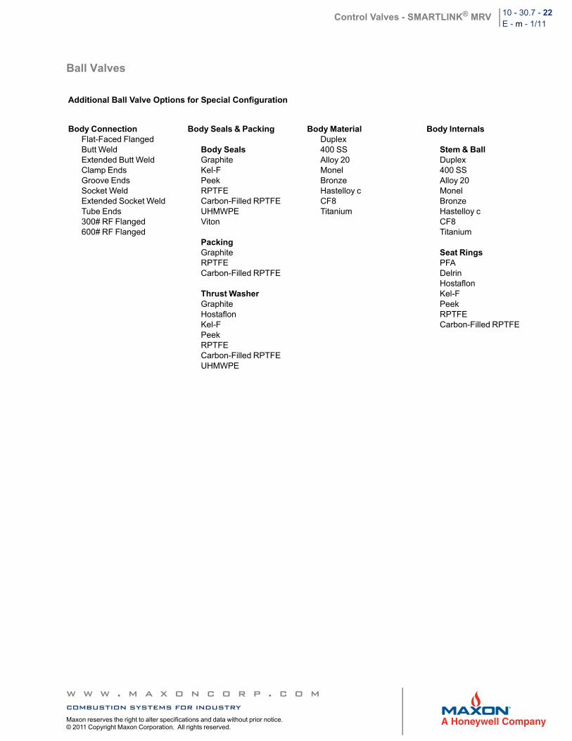
Ball Valves
Additional Ball Valve Options for Special Configuration
Body ConnectionFlat-Faced FlangedButt WeldExtended Butt WeldClamp EndsGroove EndsSocket WeldExtended Socket WeldTube Ends300# RF Flanged600# RF Flanged
Body Seals & Packing
Body SealsGraphiteKel-FPeekRPTFECarbon-Filled RPTFEUHMWPEViton
PackingGraphiteRPTFECarbon-Filled RPTFE
Thrust WasherGraphiteHostaflonKel-FPeekRPTFECarbon-Filled RPTFEUHMWPE
Body MaterialDuplex400 SSAlloy 20MonelBronzeHastelloy cCF8Titanium
Body Internals
Stem & BallDuplex400 SSAlloy 20MonelBronzeHastelloy cCF8Titanium
Seat RingsPFADelrinHostaflonKel-FPeekRPTFECarbon-Filled RPTFE
w w w . m a x o n c o r p . c o mcombustion systems for industryMaxon reserves the right to alter specifications and data without prior notice. © 2011 Copyright Maxon Corporation. All rights reserved.
Control Valves - SMARTLINK® MRV 10 - 30.7 - 23E - m - 1/11
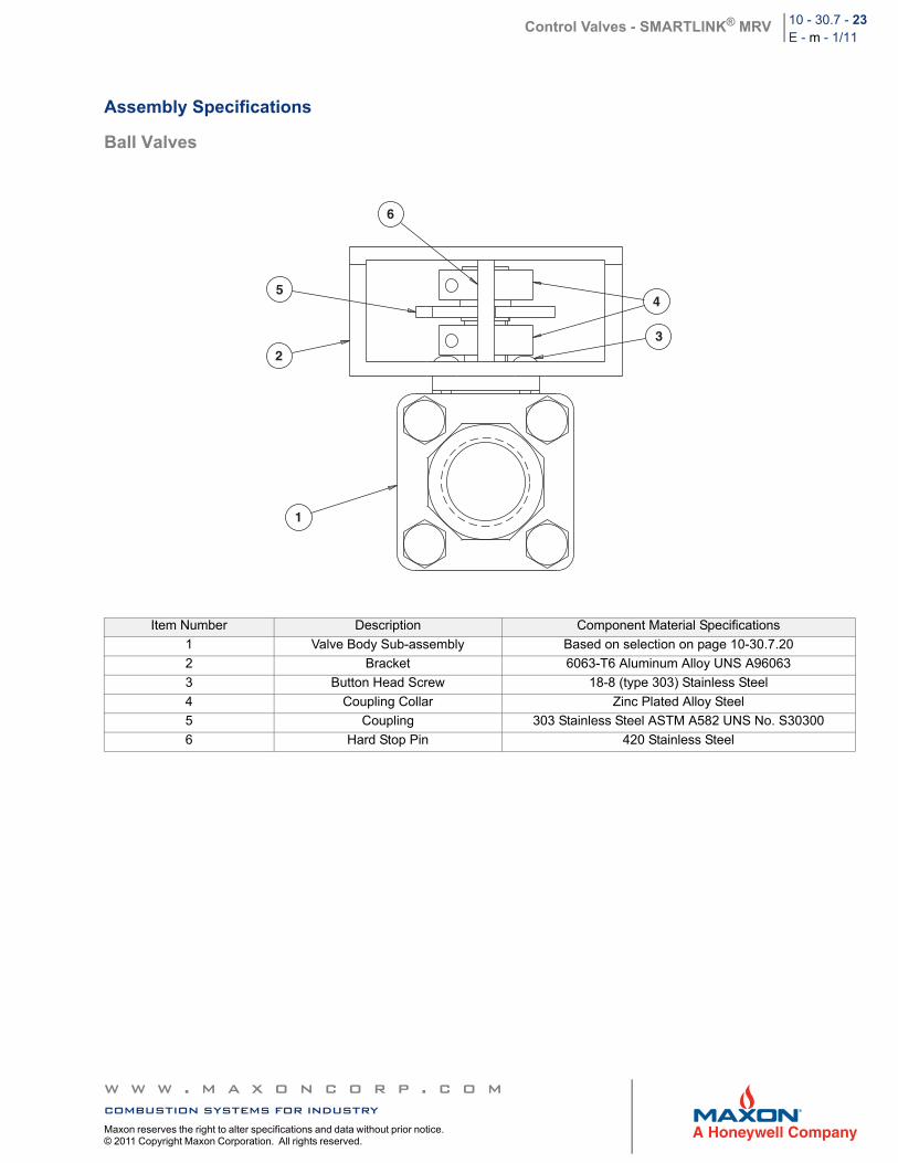
Assembly Specifications
Ball Valves
Item Number Description Component Material Specifications
1 Valve Body Sub-assembly Based on selection on page 10-30.7.20
2 Bracket 6063-T6 Aluminum Alloy UNS A96063
3 Button Head Screw 18-8 (type 303) Stainless Steel
4 Coupling Collar Zinc Plated Alloy Steel
5 Coupling 303 Stainless Steel ASTM A582 UNS No. S30300
6 Hard Stop Pin 420 Stainless Steel
6
5
2
4
3
1
w w w . m a x o n c o r p . c o mcombustion systems for industryMaxon reserves the right to alter specifications and data without prior notice. © 2011 Copyright Maxon Corporation. All rights reserved.
Control Valves - SMARTLINK® MRV 10 - 30.7 - 24E - m - 1/11
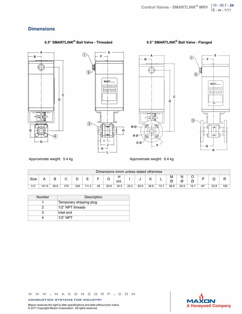
Dimensions
0.5” SMARTLINK® Ball Valve - Threaded 0.5” SMARTLINK® Ball Valve - Flanged
Approximate weight: 5.4 kg Approximate weight: 6.4 kg
Dimensions inmm unless stated otherwise
Size A B C D E F GH
oct.I J K L
MØ
NØ
OØ
P Q R
0.5” 101.6 50.8 275 249 111.3 48 50.8 30.5 25.4 50.8 36.8 73.7 88.9 60.5 15.7 45° 53.8 108
Number Description
1 Temporary shipping plug
2 1/2” NPT threads
3 Inlet end
4 1/2” NPT
AB
CD
G
G
4
3
H
IJ
KL
2
EF1 A
B
C
EF1
2
D
M Ø
N Ø
O ØP
3
QR
w w w . m a x o n c o r p . c o mcombustion systems for industryMaxon reserves the right to alter specifications and data without prior notice. © 2011 Copyright Maxon Corporation. All rights reserved.
Control Valves - SMARTLINK® MRV 10 - 30.7 - 25E - m - 1/11
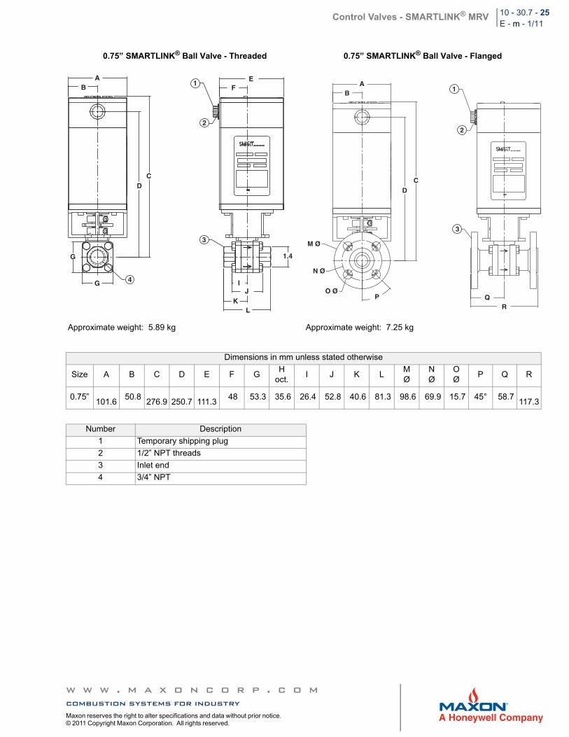
0.75” SMARTLINK® Ball Valve - Threaded 0.75” SMARTLINK® Ball Valve - Flanged
Approximate weight: 5.89 kg Approximate weight: 7.25 kg
Dimensions in mm unless stated otherwise
Size A B C D E F GH
oct.I J K L
MØ
NØ
OØ
P Q R
0.75”
101.6 50.8
276.9
250.7
111.3
48 53.3 35.6 26.4 52.8 40.6 81.3 98.6 69.9 15.7 45° 58.7
117.3
Number Description
1 Temporary shipping plug
2 1/2” NPT threads
3 Inlet end
4 3/4” NPT
AB
CD
1
2
EF
G
G 4
3
1.4
IJ
KL
AB
1
2
CD
3
QR
M Ø
N Ø
O ØP
w w w . m a x o n c o r p . c o mcombustion systems for industryMaxon reserves the right to alter specifications and data without prior notice. © 2011 Copyright Maxon Corporation. All rights reserved.
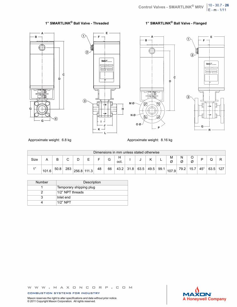
Control Valves - SMARTLINK® MRV 10 - 30.7 - 26E - m - 1/11
1” SMARTLINK® Ball Valve - Threaded 1” SMARTLINK® Ball Valve - Flanged
Approximate weight: 6.8 kg Approximate weight: 8.16 kg
Dimensions in mm unless stated otherwise
Size A B C D E F GH
oct.I J K L
MØ
NØ
OØ
P Q R
1”
101.6 50.8 283
256.8
111.3
48 66 43.2 31.8 63.5 49.5 99.1
107.9 79.2 15.7 45° 63.5 127
Number Description
1 Temporary shipping plug
2 1/2” NPT threads
3 Inlet end
4 1/2” NPT
AB
CD
EF1
2
G
G4
3
H
IJ
KL
AB
CD
EF1
2
3
QR
M Ø
N Ø
O ØP
w w w . m a x o n c o r p . c o mcombustion systems for industryMaxon reserves the right to alter specifications and data without prior notice. © 2011 Copyright Maxon Corporation. All rights reserved.
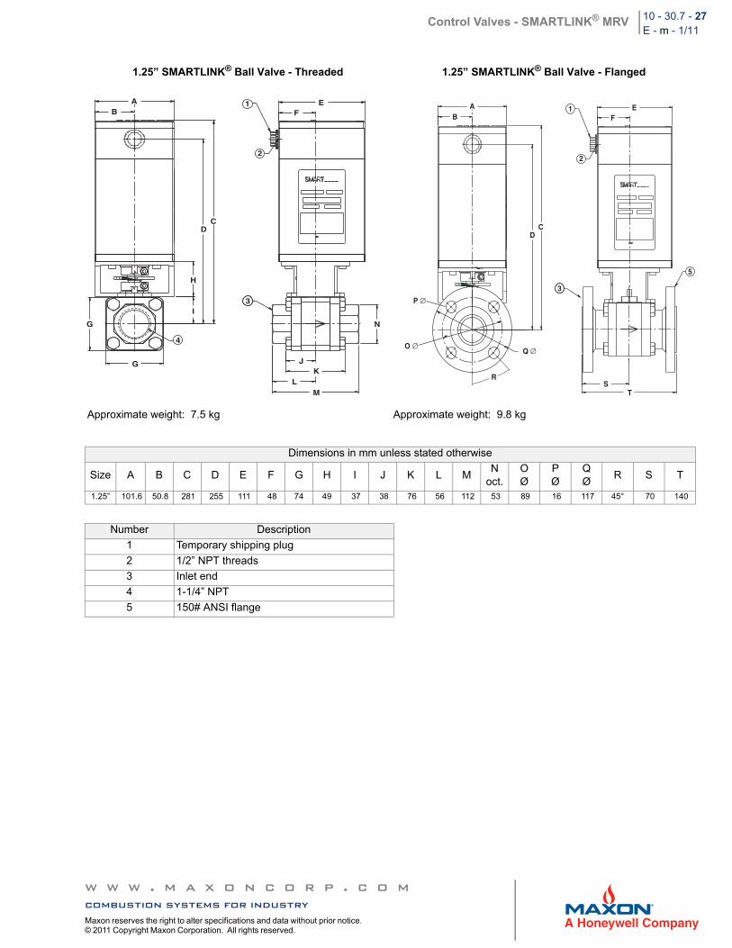
Control Valves - SMARTLINK® MRV 10 - 30.7 - 27E - m - 1/11
1.25” SMARTLINK® Ball Valve - Threaded 1.25” SMARTLINK® Ball Valve - Flanged
Approximate weight: 7.5 kg Approximate weight: 9.8 kg
Dimensions in mm unless stated otherwise
Size A B C D E F G H I J K L MN
oct.OØ
PØ
QØ
R S T
1.25” 101.6 50.8 281 255 111 48 74 49 37 38 76 56 112 53 89 16 117 45° 70 140
Number Description
1 Temporary shipping plug
2 1/2” NPT threads
3 Inlet end
4 1-1/4” NPT
5 150# ANSI flange
O C
AB
CD
H
I
G
G
4
3
JK
LM
N
2
1 EF
O C
AB
CD
3
2
1 EF
5
ST
P ∅
O ∅
R
Q ∅
w w w . m a x o n c o r p . c o mcombustion systems for industryMaxon reserves the right to alter specifications and data without prior notice. © 2011 Copyright Maxon Corporation. All rights reserved.
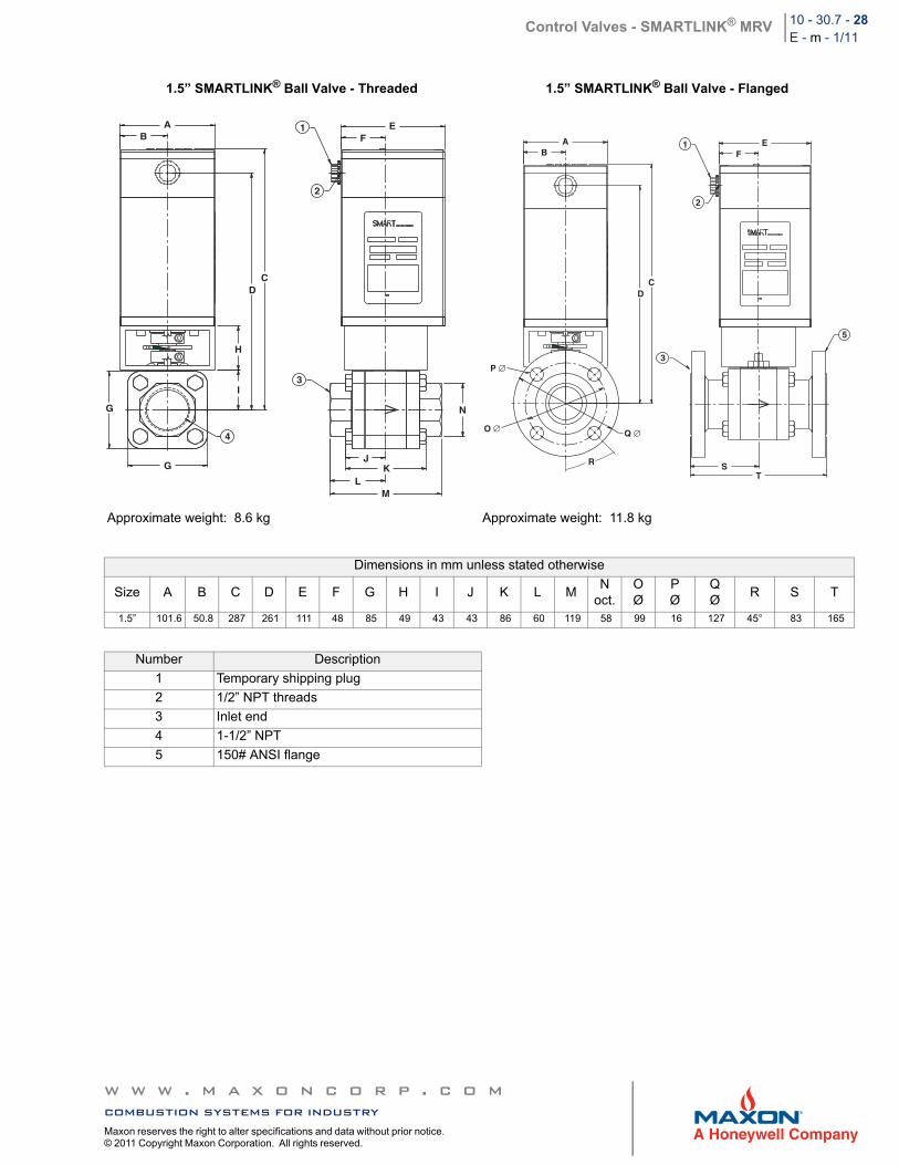
Control Valves - SMARTLINK® MRV 10 - 30.7 - 28E - m - 1/11
1.5” SMARTLINK® Ball Valve - Threaded 1.5” SMARTLINK® Ball Valve - Flanged
Approximate weight: 8.6 kg Approximate weight: 11.8 kg
Dimensions in mm unless stated otherwise
Size A B C D E F G H I J K L MN
oct.OØ
PØ
QØ
R S T
1.5” 101.6 50.8 287 261 111 48 85 49 43 43 86 60 119 58 99 16 127 45° 83 165
Number Description
1 Temporary shipping plug
2 1/2” NPT threads
3 Inlet end
4 1-1/2” NPT
5 150# ANSI flange
O C
AB
CD
H
I
4
G
G
3
JK
LM
N
1
2
EF
O C
AB
CD
3
1
2
EF
P ∅
O ∅ Q ∅
R ST
5
w w w . m a x o n c o r p . c o mcombustion systems for industryMaxon reserves the right to alter specifications and data without prior notice. © 2011 Copyright Maxon Corporation. All rights reserved.
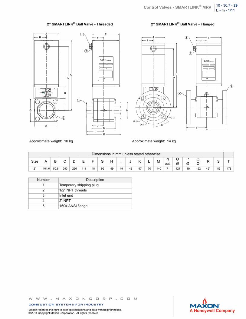
Control Valves - SMARTLINK® MRV 10 - 30.7 - 29E - m - 1/11
2” SMARTLINK® Ball Valve - Threaded 2” SMARTLINK® Ball Valve - Flanged
Approximate weight: 10 kg Approximate weight: 14 kg
Dimensions in mm unless stated otherwise
Size A B C D E F G H I J K L MN
oct.OØ
PØ
QØ
R S T
2” 101.6 50.8 293 266 111 48 95 49 49 48 97 70 140 71 121 19 152 45° 89 178
Number Description
1 Temporary shipping plug
2 1/2” NPT threads
3 Inlet end
4 2” NPT
5 150# ANSI flange
O C
AB
CD
H
I
G
G
4
3
JK
LM
N
1
2
EF A
B
CD
3
1
2
EF
ST
R
P ∅O ∅
Q ∅
5
w w w . m a x o n c o r p . c o mcombustion systems for industryMaxon reserves the right to alter specifications and data without prior notice. © 2011 Copyright Maxon Corporation. All rights reserved.
Control Valves - SMARTLINK® MRV 10 - 30.7 - 30E - m - 1/11
Model Number Description
Control Actuator
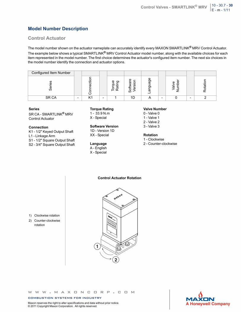
The model number shown on the actuator nameplate can accurately identify every MAXON SMARTLINK® MRV Control Actuator.
The example below shows a typical SMARTLINK® MRV Control Actuator model number, along with the available choices for each item represented in the model number. The first choice determines the actuator's configured item number. The next six choices in the model number identify the connection and actuator options.
Configured Item Number
Ser
ies
Co
nnec
tion
Torq
ue
Rat
ing
So
ftwar
eV
ersi
on
Lan
gua
ge
Val
veN
umbe
r
Ro
tatio
n
SR CA - K1 - 1 1D A - 0 - 2
Series
SR CA - SMARTLINK® MRVControl Actuator
ConnectionK1 - 1/2" Keyed Output ShaftL1 - Linkage ArmS1 - 1/2" Square Output ShaftS2 - 3/4" Square Output Shaft
Torque Rating1 - 33.9 N.mX - Special
Software Version 1D - Version 1DXX - Special
LanguageA - EnglishX - Special
Valve Number0 - Valve 01 - Valve 12 - Valve 23 - Valve 3
Rotation1 - Clockwise2 - Counter-clockwise
1) Clockwise rotation
2) Counter-clockwise rotation
Control Actuator Rotation
1
2
w w w . m a x o n c o r p . c o mcombustion systems for industryMaxon reserves the right to alter specifications and data without prior notice. © 2011 Copyright Maxon Corporation. All rights reserved.
Control Valves - SMARTLINK® MRV 10 - 30.7 - 31E - m - 1/11
Dimensions
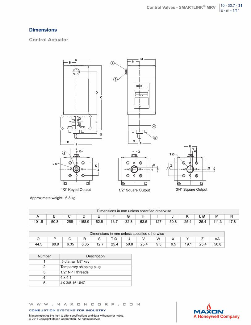
Control Actuator
Approximate weight: 6.8 kg
Dimensions in mm unless specified otherwise
A B C D E F G H I J K L Ø M N
101.6 50.8 256 168.9 62.5 13.7 32.8 63.5 127 50.8 25.4 25.4 111.3 47.8
Dimensions in mm unless specified otherwise
O P Q R S T Ø U V W X Y Z AA
44.5 88.9 6.35 6.35 12.7 25.4 50.8 25.4 9.5 9.5 19.1 25.4 50.8
Number Description
1 .5 dia. w/ 1/8” key
2 Temporary shipping plug
3 1/2” NPT threads
4 4 x 4.1
5 4X 3/8-16 UNC
AB
C
D
E
FG
HI
1J
K
KJ
L Ø
MN2
3
4
5O
P
Q
RS
T Ø
UVW
X YZ
AA
1/2” Keyed Output 1/2” Square Output 3/4” Square Output
w w w . m a x o n c o r p . c o mcombustion systems for industryMaxon reserves the right to alter specifications and data without prior notice. © 2011 Copyright Maxon Corporation. All rights reserved.
Control Valves - SMARTLINK® MRV 10 - 30.7 - 32E - m - 1/11
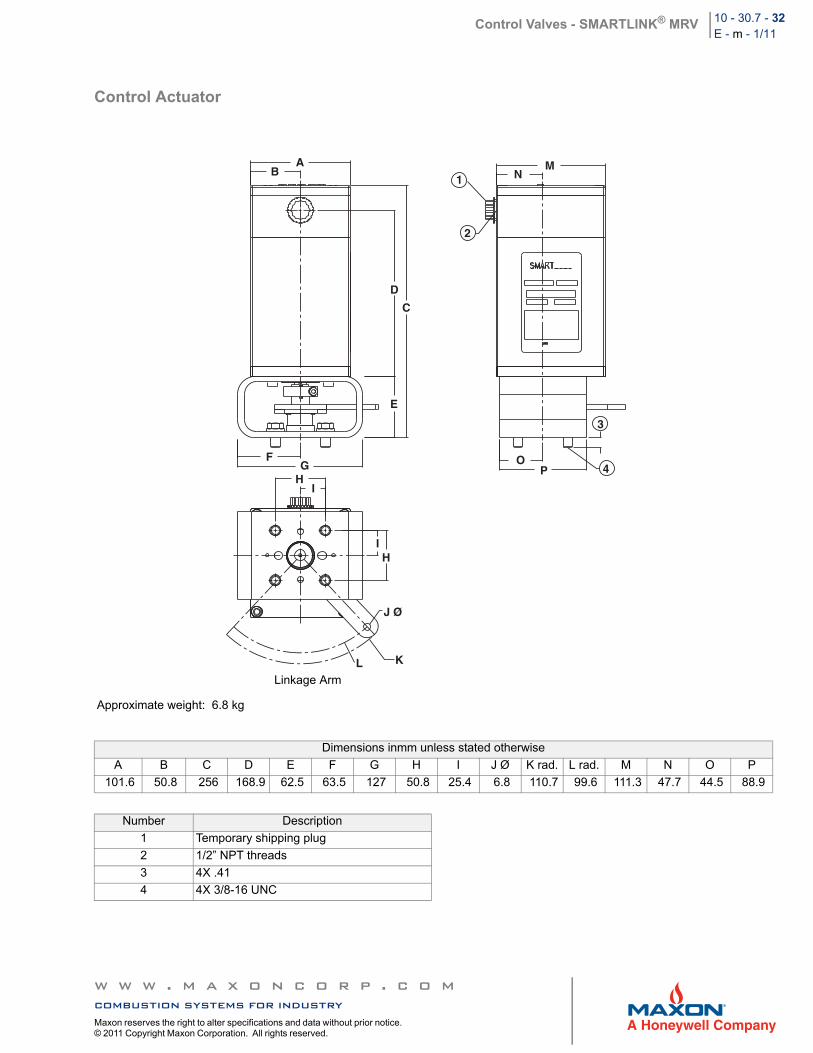
Control Actuator
Approximate weight: 6.8 kg
Dimensions inmm unless stated otherwise
A B C D E F G H I J Ø K rad. L rad. M N O P
101.6 50.8 256 168.9 62.5 63.5 127 50.8 25.4 6.8 110.7 99.6 111.3 47.7 44.5 88.9
Number Description
1 Temporary shipping plug
2 1/2” NPT threads
3 4X .41
4 4X 3/8-16 UNC
AB
C
D
E
FG
HI
IH
J Ø
KL
MN1
2
3
4O
P
Linkage Arm
w w w . m a x o n c o r p . c o mcombustion systems for industryMaxon reserves the right to alter specifications and data without prior notice. © 2011 Copyright Maxon Corporation. All rights reserved.
Control Valves - SMARTLINK® MRV 10 - 30.7 - 33E - m - 1/11
Model Number Description
Spare Actuator
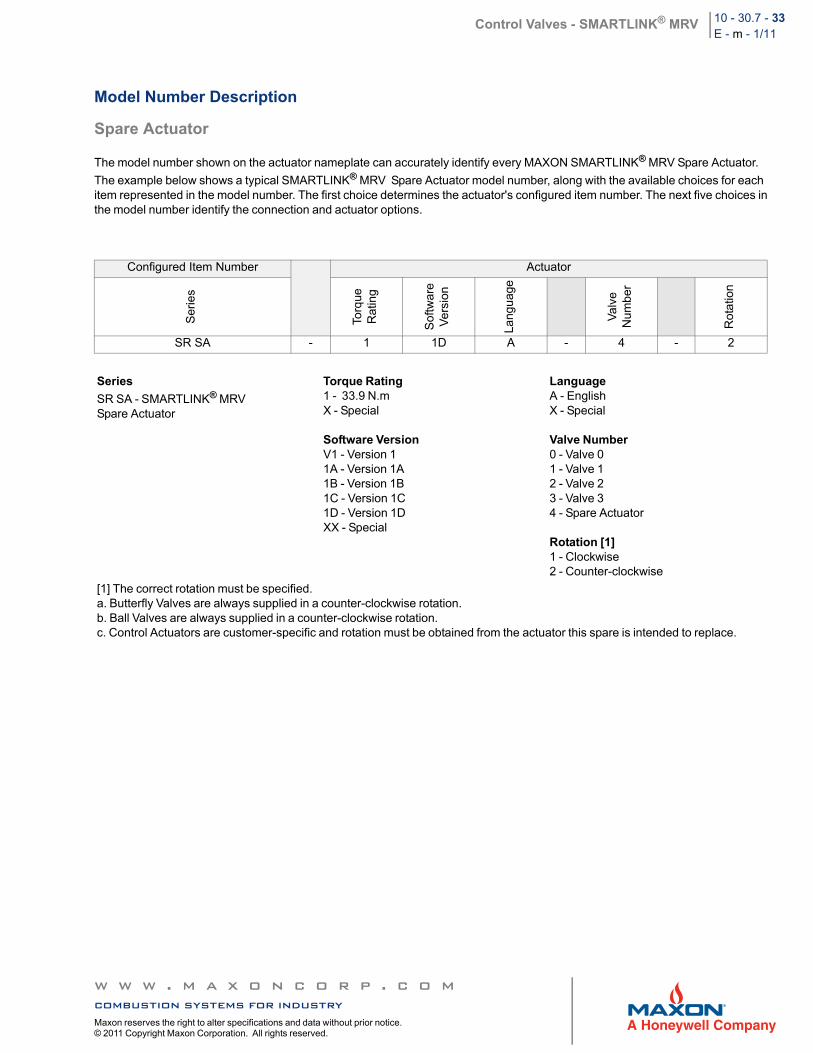
The model number shown on the actuator nameplate can accurately identify every MAXON SMARTLINK® MRV Spare Actuator.
The example below shows a typical SMARTLINK® MRV Spare Actuator model number, along with the available choices for each item represented in the model number. The first choice determines the actuator's configured item number. The next five choices in the model number identify the connection and actuator options.
Configured Item Number Actuator
Ser
ies
Torq
ueR
atin
g
Sof
twar
eV
ers
ion
Lang
uag
e
Va
lve
Num
ber
Rot
atio
n
SR SA - 1 1D A - 4 - 2
Series
SR SA - SMARTLINK® MRVSpare Actuator
Torque Rating1 - 33.9 N.mX - Special
Software Version V1 - Version 11A - Version 1A1B - Version 1B1C - Version 1C1D - Version 1DXX - Special
LanguageA - EnglishX - Special
Valve Number0 - Valve 01 - Valve 12 - Valve 23 - Valve 34 - Spare Actuator
Rotation [1]1 - Clockwise2 - Counter-clockwise
[1] The correct rotation must be specified.a. Butterfly Valves are always supplied in a counter-clockwise rotation.b. Ball Valves are always supplied in a counter-clockwise rotation.c. Control Actuators are customer-specific and rotation must be obtained from the actuator this spare is intended to replace.
w w w . m a x o n c o r p . c o mcombustion systems for industryMaxon reserves the right to alter specifications and data without prior notice. © 2011 Copyright Maxon Corporation. All rights reserved.
Control Valves - SMARTLINK® MRV 10 - 30.7 - 34E - m - 1/11
Model Number Description
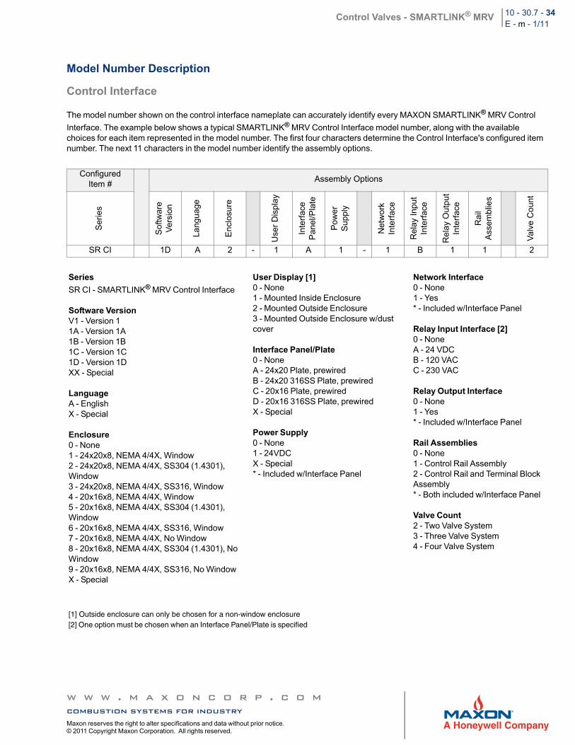
Control Interface
The model number shown on the control interface nameplate can accurately identify every MAXON SMARTLINK® MRV Control
Interface. The example below shows a typical SMARTLINK® MRV Control Interface model number, along with the available choices for each item represented in the model number. The first four characters determine the Control Interface's configured item number. The next 11 characters in the model number identify the assembly options.
Configured Item #
Assembly Options
Ser
ies
Sof
twar
e V
ers
ion
Lang
uag
e
En
clos
ure
Use
r D
ispl
ay
Inte
rfac
eP
anel
/Pla
te
Pow
erS
upp
ly
Net
wor
kIn
terf
ace
Rel
ay In
put
Inte
rfac
e
Re
lay
Ou
tput
Inte
rfac
e
Rai
lA
ssem
blie
s
Val
ve C
oun
t
SR CI 1D A 2 - 1 A 1 - 1 B 1 1 2
Series
SR CI - SMARTLINK® MRV Control Interface
Software Version V1 - Version 11A - Version 1A1B - Version 1B1C - Version 1C1D - Version 1DXX - Special
LanguageA - EnglishX - Special
Enclosure0 - None1 - 24x20x8, NEMA 4/4X, Window2 - 24x20x8, NEMA 4/4X, SS304 (1.4301), Window3 - 24x20x8, NEMA 4/4X, SS316, Window4 - 20x16x8, NEMA 4/4X, Window5 - 20x16x8, NEMA 4/4X, SS304 (1.4301), Window6 - 20x16x8, NEMA 4/4X, SS316, Window7 - 20x16x8, NEMA 4/4X, No Window8 - 20x16x8, NEMA 4/4X, SS304 (1.4301), No Window9 - 20x16x8, NEMA 4/4X, SS316, No WindowX - Special
User Display [1]0 - None1 - Mounted Inside Enclosure2 - Mounted Outside Enclosure3 - Mounted Outside Enclosure w/dust cover
Interface Panel/Plate0 - NoneA - 24x20 Plate, prewiredB - 24x20 316SS Plate, prewiredC - 20x16 Plate, prewiredD - 20x16 316SS Plate, prewiredX - Special
Power Supply0 - None1 - 24VDC X - Special* - Included w/Interface Panel
Network Interface0 - None1 - Yes* - Included w/Interface Panel
Relay Input Interface [2]0 - NoneA - 24 VDCB - 120 VACC - 230 VAC
Relay Output Interface0 - None1 - Yes* - Included w/Interface Panel
Rail Assemblies0 - None1 - Control Rail Assembly2 - Control Rail and Terminal Block Assembly* - Both included w/Interface Panel
Valve Count2 - Two Valve System3 - Three Valve System4 - Four Valve System
[1] Outside enclosure can only be chosen for a non-window enclosure[2] One option must be chosen when an Interface Panel/Plate is specified
w w w . m a x o n c o r p . c o mcombustion systems for industryMaxon reserves the right to alter specifications and data without prior notice. © 2011 Copyright Maxon Corporation. All rights reserved.
Control Valves - SMARTLINK® MRV 10 - 30.7 - 35E - m - 1/11
Dimensions
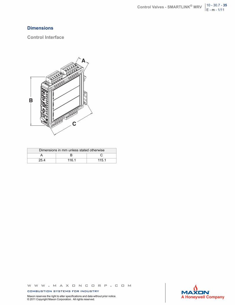
Control Interface
Dimensions in mm unless stated otherwise
A B C
25.4 116.1 115.1
A
B
C
w w w . m a x o n c o r p . c o mcombustion systems for industryMaxon reserves the right to alter specifications and data without prior notice. © 2011 Copyright Maxon Corporation. All rights reserved.
Control Valves - SMARTLINK® MRV 10 - 30.7 - 36E - m - 1/11
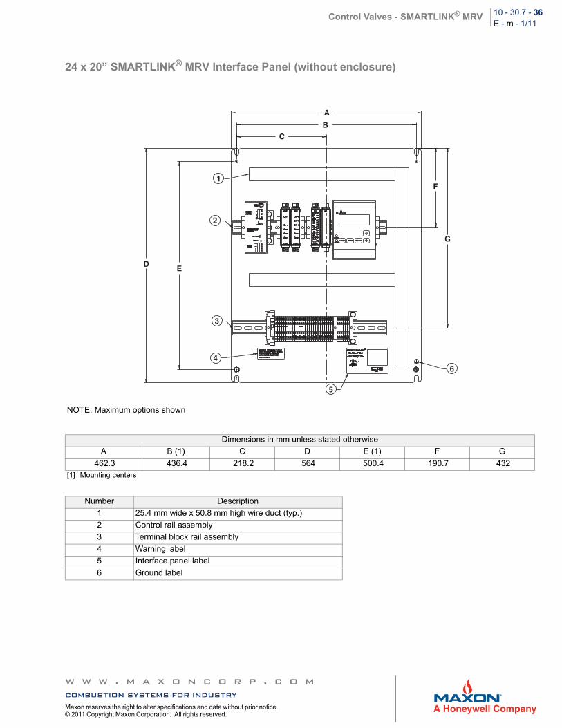
24 x 20” SMARTLINK® MRV Interface Panel (without enclosure)
NOTE: Maximum options shown
Dimensions in mm unless stated otherwise
A B (1) C D E (1) F G
462.3 436.4 218.2 564 500.4 190.7 432[1] Mounting centers
Number Description
1 25.4 mm wide x 50.8 mm high wire duct (typ.)
2 Control rail assembly
3 Terminal block rail assembly
4 Warning label
5 Interface panel label
6 Ground label
A
BC
1
2
D E
3
4
5
6
F
G
w w w . m a x o n c o r p . c o mcombustion systems for industryMaxon reserves the right to alter specifications and data without prior notice. © 2011 Copyright Maxon Corporation. All rights reserved.
Control Valves - SMARTLINK® MRV 10 - 30.7 - 37E - m - 1/11
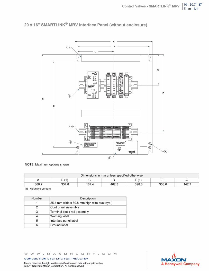
20 x 16” SMARTLINK® MRV Interface Panel (without enclosure)
NOTE: Maximum options shown
Dimensions in mm unless specified otherwise
A B (1) C D E (1) F G
360.7 334.8 167.4 462.3 398.8 358.6 142.7[1] Mounting centers
Number Description
1 25.4 mm wide x 50.8 mm high wire duct (typ.)
2 Control rail assembly
3 Terminal block rail assembly
4 Warning label
5 Interface panel label
6 Ground label
A
B
C
1
D
E
2
3
4
5
6
F
G
w w w . m a x o n c o r p . c o mcombustion systems for industryMaxon reserves the right to alter specifications and data without prior notice. © 2011 Copyright Maxon Corporation. All rights reserved.
Control Valves - SMARTLINK® MRV 10 - 30.7 - 38E - m - 1/11
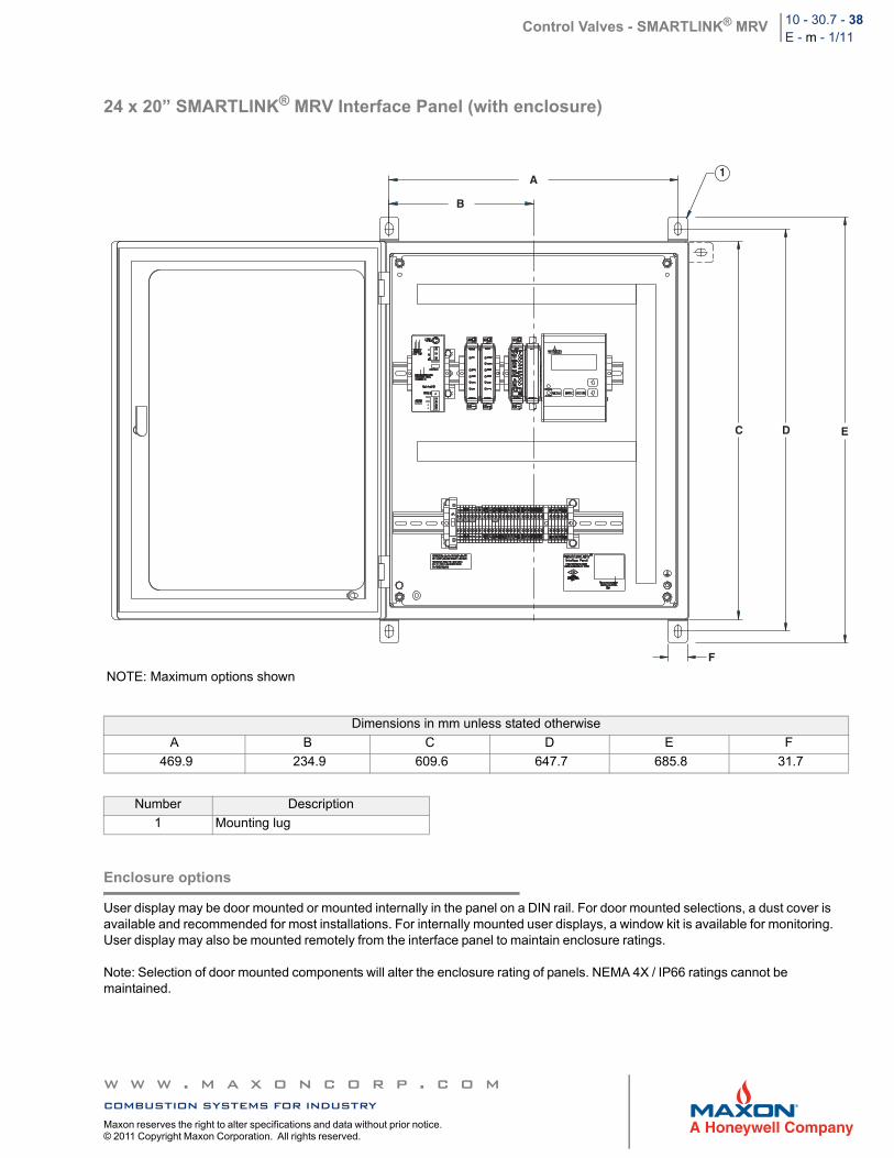
24 x 20” SMARTLINK® MRV Interface Panel (with enclosure)
Enclosure options
User display may be door mounted or mounted internally in the panel on a DIN rail. For door mounted selections, a dust cover is available and recommended for most installations. For internally mounted user displays, a window kit is available for monitoring. User display may also be mounted remotely from the interface panel to maintain enclosure ratings.
Note: Selection of door mounted components will alter the enclosure rating of panels. NEMA 4X / IP66 ratings cannot be maintained.
NOTE: Maximum options shown
Dimensions in mm unless stated otherwise
A B C D E F
469.9 234.9 609.6 647.7 685.8 31.7
Number Description
1 Mounting lug
1A
B
C D E
F
w w w . m a x o n c o r p . c o mcombustion systems for industryMaxon reserves the right to alter specifications and data without prior notice. © 2011 Copyright Maxon Corporation. All rights reserved.
Control Valves - SMARTLINK® MRV 10 - 30.7 - 39E - m - 1/11
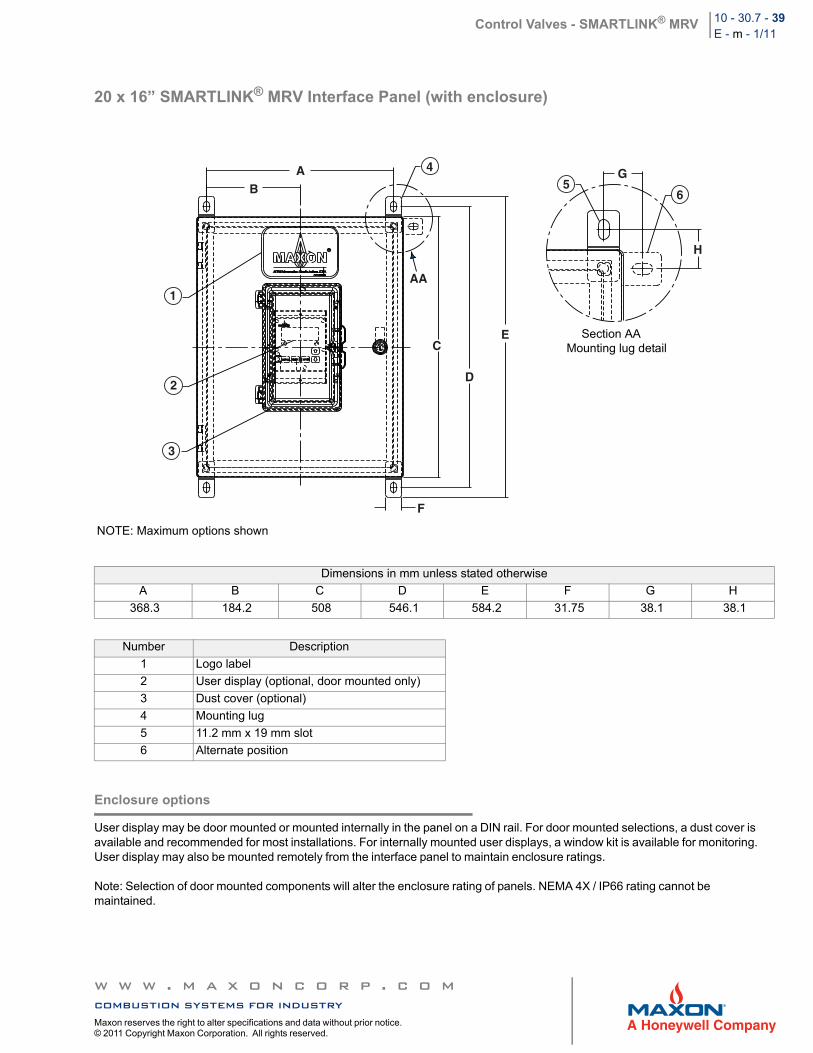
20 x 16” SMARTLINK® MRV Interface Panel (with enclosure)
Enclosure options
User display may be door mounted or mounted internally in the panel on a DIN rail. For door mounted selections, a dust cover is available and recommended for most installations. For internally mounted user displays, a window kit is available for monitoring. User display may also be mounted remotely from the interface panel to maintain enclosure ratings.
Note: Selection of door mounted components will alter the enclosure rating of panels. NEMA 4X / IP66 rating cannot be maintained.
NOTE: Maximum options shown
Dimensions in mm unless stated otherwise
A B C D E F G H
368.3 184.2 508 546.1 584.2 31.75 38.1 38.1
Number Description
1 Logo label
2 User display (optional, door mounted only)
3 Dust cover (optional)
4 Mounting lug
5 11.2 mm x 19 mm slot
6 Alternate position
4
AA1
2
3
56
AB
F
C
D
E
G
H
Section AAMounting lug detail
w w w . m a x o n c o r p . c o mcombustion systems for industryMaxon reserves the right to alter specifications and data without prior notice. © 2011 Copyright Maxon Corporation. All rights reserved.
Control Valves - SMARTLINK® MRV 10 - 30.7 - 40E - m - 1/11
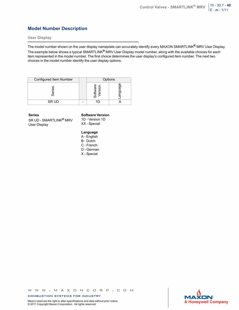
Model Number Description
User Display
The model number shown on the user display nameplate can accurately identify every MAXON SMARTLINK® MRV User Display.
The example below shows a typical SMARTLINK® MRV User Display model number, along with the available choices for each item represented in the model number. The first choice determines the user display's configured item number. The next two choices in the model number identify the user display options.
Configured Item Number Options
Ser
ies
Sof
twar
e V
ersi
on
Lan
guag
e
SR UD - 1D A
Series
SR UD - SMARTLINK® MRVUser Display
Software Version 1D - Version 1DXX - Special
LanguageA - EnglishB - DutchC - FrenchD - GermanX - Special
w w w . m a x o n c o r p . c o mcombustion systems for industryMaxon reserves the right to alter specifications and data without prior notice. © 2011 Copyright Maxon Corporation. All rights reserved.
Control Valves - SMARTLINK® MRV 10 - 30.7 - 41E - m - 1/11
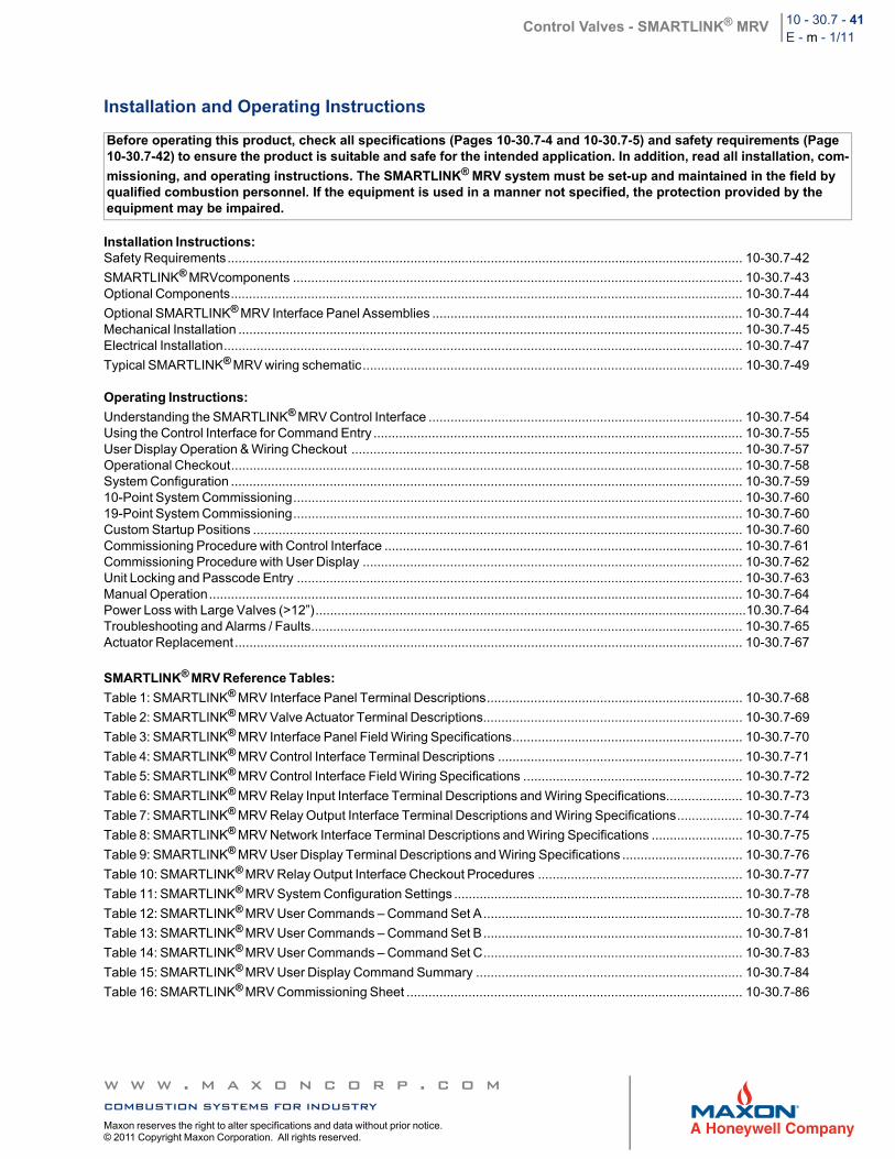
Installation and Operating Instructions
Installation Instructions:Safety Requirements............................................................................................................................................. 10-30.7-42
SMARTLINK® MRVcomponents ........................................................................................................................... 10-30.7-43Optional Components............................................................................................................................................ 10-30.7-44
Optional SMARTLINK® MRV Interface Panel Assemblies ..................................................................................... 10-30.7-44Mechanical Installation .......................................................................................................................................... 10-30.7-45Electrical Installation.............................................................................................................................................. 10-30.7-47
Typical SMARTLINK® MRV wiring schematic........................................................................................................ 10-30.7-49
Operating Instructions:
Understanding the SMARTLINK® MRV Control Interface ...................................................................................... 10-30.7-54Using the Control Interface for Command Entry ..................................................................................................... 10-30.7-55User Display Operation & Wiring Checkout ........................................................................................................... 10-30.7-57Operational Checkout............................................................................................................................................ 10-30.7-58System Configuration ............................................................................................................................................ 10-30.7-5910-Point System Commissioning........................................................................................................................... 10-30.7-6019-Point System Commissioning........................................................................................................................... 10-30.7-60Custom Startup Positions ...................................................................................................................................... 10-30.7-60Commissioning Procedure with Control Interface .................................................................................................. 10-30.7-61Commissioning Procedure with User Display ........................................................................................................ 10-30.7-62Unit Locking and Passcode Entry .......................................................................................................................... 10-30.7-63Manual Operation.................................................................................................................................................. 10-30.7-64Power Loss with Large Valves (>12”)......................................................................................................................10.30.7-64Troubleshooting and Alarms / Faults...................................................................................................................... 10-30.7-65Actuator Replacement........................................................................................................................................... 10-30.7-67
SMARTLINK® MRV Reference Tables:
Table 1: SMARTLINK® MRV Interface Panel Terminal Descriptions...................................................................... 10-30.7-68
Table 2: SMARTLINK® MRV Valve Actuator Terminal Descriptions....................................................................... 10-30.7-69
Table 3: SMARTLINK® MRV Interface Panel Field Wiring Specifications............................................................... 10-30.7-70
Table 4: SMARTLINK® MRV Control Interface Terminal Descriptions ................................................................... 10-30.7-71
Table 5: SMARTLINK® MRV Control Interface Field Wiring Specifications ............................................................ 10-30.7-72
Table 6: SMARTLINK® MRV Relay Input Interface Terminal Descriptions and Wiring Specifications..................... 10-30.7-73
Table 7: SMARTLINK® MRV Relay Output Interface Terminal Descriptions and Wiring Specifications.................. 10-30.7-74
Table 8: SMARTLINK® MRV Network Interface Terminal Descriptions and Wiring Specifications ......................... 10-30.7-75
Table 9: SMARTLINK® MRV User Display Terminal Descriptions and Wiring Specifications ................................. 10-30.7-76
Table 10: SMARTLINK® MRV Relay Output Interface Checkout Procedures ........................................................ 10-30.7-77
Table 11: SMARTLINK® MRV System Configuration Settings ............................................................................... 10-30.7-78
Table 12: SMARTLINK® MRV User Commands – Command Set A....................................................................... 10-30.7-78
Table 13: SMARTLINK® MRV User Commands – Command Set B....................................................................... 10-30.7-81
Table 14: SMARTLINK® MRV User Commands – Command Set C....................................................................... 10-30.7-83
Table 15: SMARTLINK® MRV User Display Command Summary ......................................................................... 10-30.7-84
Table 16: SMARTLINK® MRV Commissioning Sheet ............................................................................................ 10-30.7-86
Before operating this product, check all specifications (Pages 10-30.7-4 and 10-30.7-5) and safety requirements (Page 10-30.7-42) to ensure the product is suitable and safe for the intended application. In addition, read all installation, com-
missioning, and operating instructions. The SMARTLINK® MRV system must be set-up and maintained in the field by qualified combustion personnel. If the equipment is used in a manner not specified, the protection provided by the equipment may be impaired.
w w w . m a x o n c o r p . c o mcombustion systems for industryMaxon reserves the right to alter specifications and data without prior notice. © 2011 Copyright Maxon Corporation. All rights reserved.
Control Valves - SMARTLINK® MRV 10 - 30.7 - 42E - m - 1/11
Installation Instructions
Safety Requirements
1. The SMARTLINK® MRV system should be used for positioning of multiple valves/dampers to control the air/fuel ratio to industrial/commercial burners. The product is intended to replace mechanically or pneumatically linked air/fuel ratio control equipment in combustion applications that can benefit from increased positioning repeatability and tamper resistance. If the equipment is used in a manner not specified, the protection provided by the equipment may be impaired.
2. This product performs fail-safe air and fuel valve positioning only and does NOT include any air proving, flow monitoring, flame detection, or burner management functions. This product operates in response to burner management start-up commands (i.e. Purge, Light-off, Modulate) and to the temperature controller's output (or Firing Rate command) after burner start-up.
3. The SMARTLINK® MRV system is only responsible for proper positioning of valves/dampers attached to its actuators. If burner air/fuel ratio can be significantly affected by other control motors, fans, variable frequency drives, or large changes in process operating conditions, it is the commissioning engineer's responsibility to apply external equipment to detect unsafe air/fuel ratio operating conditions.
4. This product must be set-up and maintained by qualified combustion personnel. Before operating this product, read all installation, commissioning, and operating instructions (pages 10-30.7-42 through 10-30.7-88). Review all product specifications on pages 10-30.7-4 and 10-30.7-5 to ensure the product is suitable for the intended application. During the burner commissioning process, external
equipment (i.e. flow/pressure devices, O2 analyzer, etc.) or a view of the burner flame is required to ensure proper valve position set-up.
5. This product must be electrically interfaced to the burner management system's permissive circuit or the automatic burner control's
safety circuit. This important wiring requirement ensures that any failure within the SMARTLINK® MRV system can shut down the combustion system or disable a start-up sequence by turning off the main gas supply to the burner (i.e. de-energizing fuel shut-off valves). Specifically, MAXON Relay Output Interface contacts (CE1/CE1R, CE2/CE2R, CO1/CO1R) must be connected in series with the permissive circuit. If the minimum system is purchased and the Relay Output Interface is not provided, it is the commissioning engineer's responsibility to connect the MAXON Control Interface relay drive outputs (RO2 and RO5) to appropriate interface relays for safe shut down.
6. A current loop output signal (OUT+/OUT- of the Control Interface) is provided for optional monitoring of the start-up state, firing rate, and valve position (during commissioning). This signal is not designed as a fail-safe output and should not be used by external
equipment to shut down the combustion system without the use of the SMARTLINK® MRV discrete permissive outputs (as discussed in the previous safety requirement).
7. After mechanical replacement and re-calibration of a valve actuator, the previously commissioned valve positions must be re-verified.
8. The SMARTLINK® MRV Relay Output Interface (ROI), Purge Position Proven (PPP) and Light-off Position Proven (LPP) signals should be connected to the burner management (or automatic burner control) if a purge and light-off command sequence is required. These output signals are used to confirm the purge and light-off positions. If the optional Relay Output Interface is not purchased, Control Interface relay drive signals RO3 and RO4 must be properly connected to customer-supplied interface relays.
9. If the power supply is not MAXON-supplied, a SELV (Safety Extra Low Voltage) rated supply with 24VDC output must be provided.
10. If the components of a SMARTLINK® MRV system are ordered separately (i.e. without a factory-wired Interface Panel assembly), the
commissioning engineer must incorporate a switch or circuit breaker that is in close proximity to the SMARTLINK® system. The switch or breaker must be marked as the disconnection device for the equipment.
11. To avoid unsafe operating conditions or injury to fingers in the valve adapter assembly, turn off power to the system before actuator replacement or valve body (or damper) servicing is performed. Read and follow all instructions for actuator removal and re-installation as described on Page 10-30.7-67. After actuator replacement or valve body servicing, the commissioning engineer must verify burner performance through the entire operating range and re-adjust valve positions (for the replaced actuator) as required. Refer to the Commissioning Procedures on Pages10-30.7-60 through 10-30.7-62. After any actuator replacement or valve body servicing, the commissioning engineer must also confirm that the valve actuator number "selected" for re-adjustment (using the Control Interface or User Display) is attached to a known valve body or damper. If a User Display is purchased, the fluid type associated with each valve actuator should be defined as described in step a of the Commissioning Procedure on Page 10-30.7-62 and this will avoid any confusion on which actuator controls which valve. Actuators purchased as part of a 2, 3 or 4 valve actuator system are numbered electronically during manufacturing as #0, #1, #2 and #3. A spare actuator is always identified as #4 and is changed to a #0, 1, 2 or 3 during the replacement procedure. A green diagnostic LED in the actuator's wiring compartment and labeled "DIAG" indicates the valve number by blinking 0 (always ON), 1, 2, 3 or 4 times per second. On the actuator label, the last digit of the model number also indicates the valve actuator's number (with the exception of the spare actuator).
w w w . m a x o n c o r p . c o mcombustion systems for industryMaxon reserves the right to alter specifications and data without prior notice. © 2011 Copyright Maxon Corporation. All rights reserved.
Control Valves - SMARTLINK® MRV 10 - 30.7 - 43E - m - 1/11
SMARTLINK® MRV Components
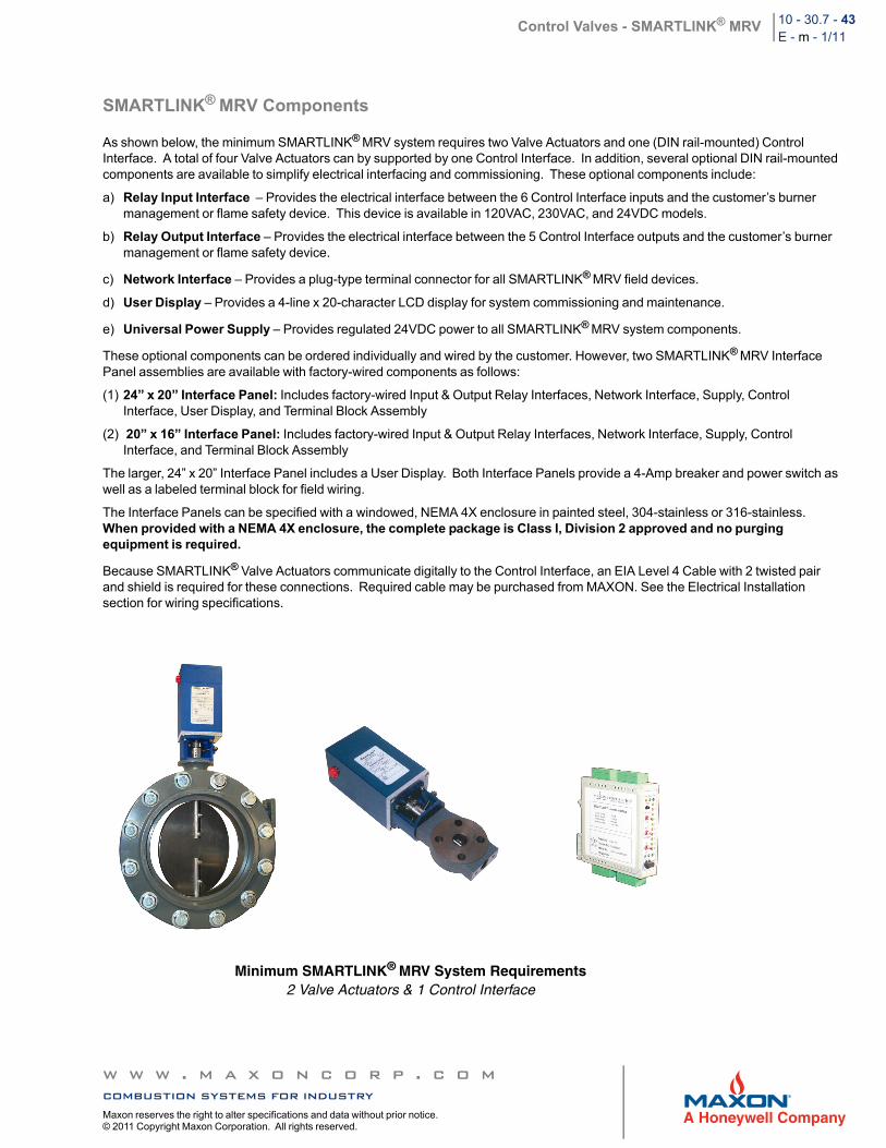
As shown below, the minimum SMARTLINK® MRV system requires two Valve Actuators and one (DIN rail-mounted) Control Interface. A total of four Valve Actuators can by supported by one Control Interface. In addition, several optional DIN rail-mounted components are available to simplify electrical interfacing and commissioning. These optional components include:
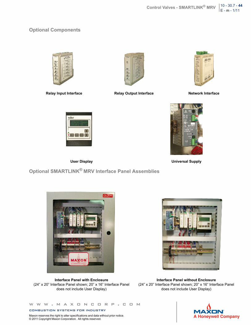
a) Relay Input Interface – Provides the electrical interface between the 6 Control Interface inputs and the customer’s burner management or flame safety device. This device is available in 120VAC, 230VAC, and 24VDC models.
b) Relay Output Interface – Provides the electrical interface between the 5 Control Interface outputs and the customer’s burner management or flame safety device.
c) Network Interface – Provides a plug-type terminal connector for all SMARTLINK® MRV field devices.
d) User Display – Provides a 4-line x 20-character LCD display for system commissioning and maintenance.
e) Universal Power Supply – Provides regulated 24VDC power to all SMARTLINK® MRV system components.
These optional components can be ordered individually and wired by the customer. However, two SMARTLINK® MRV Interface Panel assemblies are available with factory-wired components as follows:
(1) 24” x 20” Interface Panel: Includes factory-wired Input & Output Relay Interfaces, Network Interface, Supply, Control Interface, User Display, and Terminal Block Assembly
(2) 20” x 16” Interface Panel: Includes factory-wired Input & Output Relay Interfaces, Network Interface, Supply, Control Interface, and Terminal Block Assembly
The larger, 24” x 20” Interface Panel includes a User Display. Both Interface Panels provide a 4-Amp breaker and power switch as well as a labeled terminal block for field wiring.
The Interface Panels can be specified with a windowed, NEMA 4X enclosure in painted steel, 304-stainless or 316-stainless. When provided with a NEMA 4X enclosure, the complete package is Class I, Division 2 approved and no purging equipment is required.
Because SMARTLINK® Valve Actuators communicate digitally to the Control Interface, an EIA Level 4 Cable with 2 twisted pair and shield is required for these connections. Required cable may be purchased from MAXON. See the Electrical Installation section for wiring specifications.
Minimum SMARTLINK® MRV System Requirements2 Valve Actuators & 1 Control Interface
w w w . m a x o n c o r p . c o mcombustion systems for industryMaxon reserves the right to alter specifications and data without prior notice. © 2011 Copyright Maxon Corporation. All rights reserved.
Control Valves - SMARTLINK® MRV 10 - 30.7 - 44E - m - 1/11
Optional Components
Optional SMARTLINK® MRV Interface Panel Assemblies
Relay Input Interface Relay Output Interface Network Interface
User Display Universal Supply
Interface Panel with Enclosure(24” x 20” Interface Panel shown; 20” x 16” Interface Panel
does not include User Display)
Interface Panel without Enclosure(24” x 20” Interface Panel shown; 20” x 16” Interface Panel
does not include User Display)
w w w . m a x o n c o r p . c o mcombustion systems for industryMaxon reserves the right to alter specifications and data without prior notice. © 2011 Copyright Maxon Corporation. All rights reserved.
Control Valves - SMARTLINK® MRV 10 - 30.7 - 45E - m - 1/11
Mechanical Installation
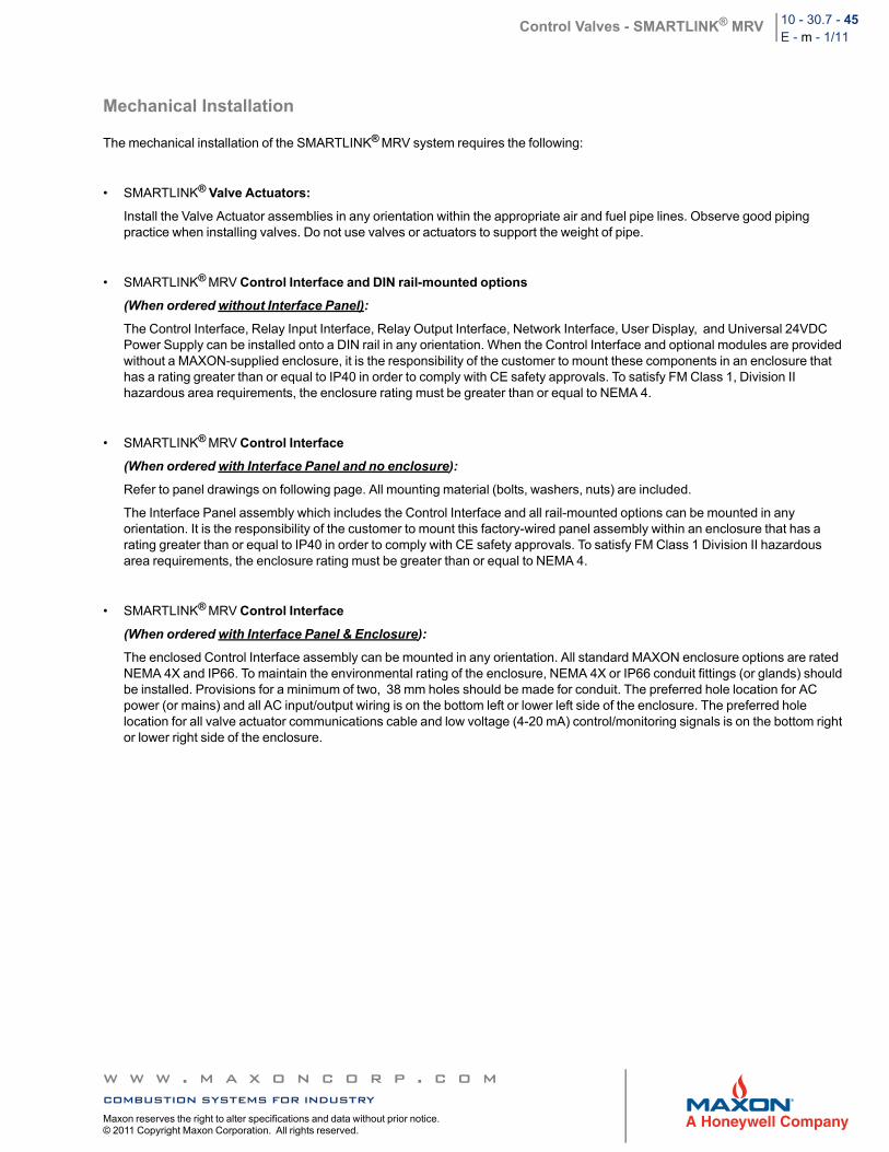
The mechanical installation of the SMARTLINK® MRV system requires the following:
• SMARTLINK® Valve Actuators:
Install the Valve Actuator assemblies in any orientation within the appropriate air and fuel pipe lines. Observe good piping practice when installing valves. Do not use valves or actuators to support the weight of pipe.
• SMARTLINK® MRV Control Interface and DIN rail-mounted options
(When ordered without Interface Panel):
The Control Interface, Relay Input Interface, Relay Output Interface, Network Interface, User Display, and Universal 24VDC Power Supply can be installed onto a DIN rail in any orientation. When the Control Interface and optional modules are provided without a MAXON-supplied enclosure, it is the responsibility of the customer to mount these components in an enclosure that has a rating greater than or equal to IP40 in order to comply with CE safety approvals. To satisfy FM Class 1, Division II hazardous area requirements, the enclosure rating must be greater than or equal to NEMA 4.
• SMARTLINK® MRV Control Interface
(When ordered with Interface Panel and no enclosure):
Refer to panel drawings on following page. All mounting material (bolts, washers, nuts) are included.
The Interface Panel assembly which includes the Control Interface and all rail-mounted options can be mounted in any orientation. It is the responsibility of the customer to mount this factory-wired panel assembly within an enclosure that has a rating greater than or equal to IP40 in order to comply with CE safety approvals. To satisfy FM Class 1 Division II hazardous area requirements, the enclosure rating must be greater than or equal to NEMA 4.
• SMARTLINK® MRV Control Interface
(When ordered with Interface Panel & Enclosure):
The enclosed Control Interface assembly can be mounted in any orientation. All standard MAXON enclosure options are rated NEMA 4X and IP66. To maintain the environmental rating of the enclosure, NEMA 4X or IP66 conduit fittings (or glands) should be installed. Provisions for a minimum of two, 38 mm holes should be made for conduit. The preferred hole location for AC power (or mains) and all AC input/output wiring is on the bottom left or lower left side of the enclosure. The preferred hole location for all valve actuator communications cable and low voltage (4-20 mA) control/monitoring signals is on the bottom right or lower right side of the enclosure.
w w w . m a x o n c o r p . c o mcombustion systems for industryMaxon reserves the right to alter specifications and data without prior notice. © 2011 Copyright Maxon Corporation. All rights reserved.
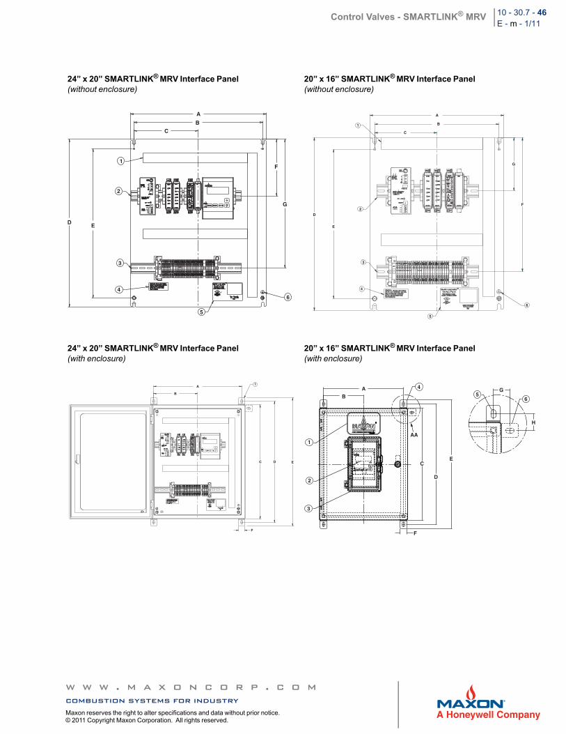
Control Valves - SMARTLINK® MRV 10 - 30.7 - 46E - m - 1/11
24” x 20” SMARTLINK® MRV Interface Panel(without enclosure)
20” x 16” SMARTLINK® MRV Interface Panel(without enclosure)
24” x 20” SMARTLINK® MRV Interface Panel(with enclosure)
20” x 16” SMARTLINK® MRV Interface Panel(with enclosure)
A
BC
1
2
D E
3
4
5
6
F
G
A
B
C
1
D
E
2
3
4
5
6
F
G
1A
B
C D E
F
4
AA1
2
3
56
AB
F
C
D
E
G
H
w w w . m a x o n c o r p . c o mcombustion systems for industryMaxon reserves the right to alter specifications and data without prior notice. © 2011 Copyright Maxon Corporation. All rights reserved.
Control Valves - SMARTLINK® MRV 10 - 30.7 - 47E - m - 1/11
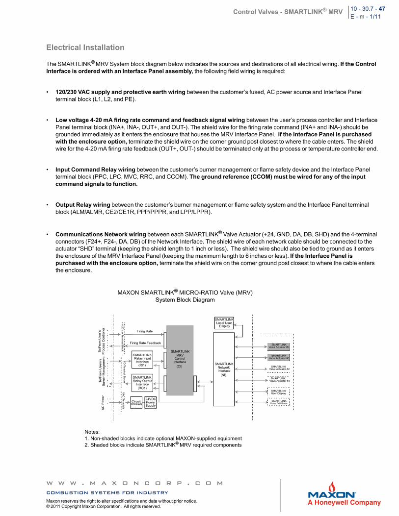
Electrical Installation
The SMARTLINK® MRV System block diagram below indicates the sources and destinations of all electrical wiring. If the Control Interface is ordered with an Interface Panel assembly, the following field wiring is required:
• 120/230 VAC supply and protective earth wiring between the customer’s fused, AC power source and Interface Panel terminal block (L1, L2, and PE).
• Low voltage 4-20 mA firing rate command and feedback signal wiring between the user’s process controller and Interface Panel terminal block (INA+, INA-, OUT+, and OUT-). The shield wire for the firing rate command (INA+ and INA-) should be grounded immediately as it enters the enclosure that houses the MRV Interface Panel. If the Interface Panel is purchased with the enclosure option, terminate the shield wire on the corner ground post closest to where the cable enters. The shield wire for the 4-20 mA firing rate feedback (OUT+, OUT-) should be terminated only at the process or temperature controller end.
• Input Command Relay wiring between the customer’s burner management or flame safety device and the Interface Panel terminal block (PPC, LPC, MVC, RRC, and CCOM). The ground reference (CCOM) must be wired for any of the input command signals to function.
• Output Relay wiring between the customer’s burner management or flame safety system and the Interface Panel terminal block (ALM/ALMR, CE2/CE1R, PPP/PPPR, and LPP/LPPR).
• Communications Network wiring between each SMARTLINK® Valve Actuator (+24, GND, DA, DB, SHD) and the 4-terminal connectors (F24+, F24-, DA, DB) of the Network Interface. The shield wire of each network cable should be connected to the actuator “SHD” terminal (keeping the shield length to 1 inch or less). The shield wire should also be tied to ground as it enters the enclosure of the MRV Interface Panel (keeping the maximum length to 6 inches or less). If the Interface Panel is purchased with the enclosure option, terminate the shield wire on the corner ground post closest to where the cable enters the enclosure.
MAXON SMARTLINK® MICRO-RATIO Valve (MRV)System Block Diagram
AC
Pow
er
To/F
rom
Use
rs’s
B
urne
r M
ana
gem
ent
To/F
rom
Use
r’s
Pro
cess
Con
tro
ller
Firing Rate
Firing Rate Feedback
SMARTLINKRelay InputInterface
(RI1)
SMARTLINKRelay Output
Interface(RO1)
CircuitBreaker
24VDCPowerSupply
SMARTLINKLocal User
Display
SMARTLINKMRV
ControlInterface
(CI)SMARTLINK
NetworkInterface
(NI)
SMARTLINKValve Actuator #0
SMARTLINKValve Actuator #1
SMARTLINKValve Actuator #2
SMARTLINKValve Actuator #3
SMARTLINKUser Display
SMARTLINKFuture Field Device
4-2
0 m
A Te
rmin
al B
lock
I/O Te
rmin
al B
locks
VA
C Te
rmin
als
Notes:1. Non-shaded blocks indicate optional MAXON-supplied equipment2. Shaded blocks indicate SMARTLINK® MRV required components
w w w . m a x o n c o r p . c o mcombustion systems for industryMaxon reserves the right to alter specifications and data without prior notice. © 2011 Copyright Maxon Corporation. All rights reserved.
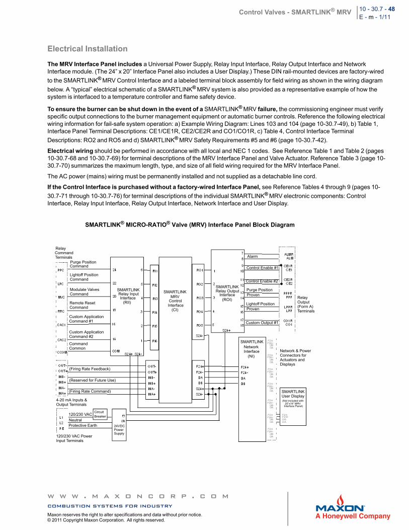
Control Valves - SMARTLINK® MRV 10 - 30.7 - 48E - m - 1/11
Electrical Installation
The MRV Interface Panel includes a Universal Power Supply, Relay Input Interface, Relay Output Interface and Network Interface module. (The 24” x 20” Interface Panel also includes a User Display.) These DIN rail-mounted devices are factory-wired
to the SMARTLINK® MRV Control Interface and a labeled terminal block assembly for field wiring as shown in the wiring diagram
below. A “typical” electrical schematic of a SMARTLINK® MRV system is also provided as a representative example of how the system is interfaced to a temperature controller and flame safety device.
To ensure the burner can be shut down in the event of a SMARTLINK® MRV failure, the commissioning engineer must verify specific output connections to the burner management equipment or automatic burner controls. Reference the following electrical wiring information for fail-safe system operation: a) Example Wiring Diagram: Lines 103 and 104 (page 10-30.7-49), b) Table 1, Interface Panel Terminal Descriptions: CE1/CE1R, CE2/CE2R and CO1/CO1R, c) Table 4, Control Interface Terminal
Descriptions: RO2 and RO5 and d) SMARTLINK® MRV Safety Requirements #5 and #6 (page 10-30.7-42).
Electrical wiring should be performed in accordance with all local and NEC 1 codes. See Reference Table 1 and Table 2 (pages 10-30.7-68 and 10-30.7-69) for terminal descriptions of the MRV Interface Panel and Valve Actuator. Reference Table 3 (page 10-30.7-70) summarizes the maximum length, type, and size of all field wiring required for the MRV Interface Panel.
The AC power (mains) wiring must be permanently installed and not supplied as a detachable line cord.
If the Control Interface is purchased without a factory-wired Interface Panel, see Reference Tables 4 through 9 (pages 10-
30.7-71 through 10-30.7-76) for terminal descriptions of the individual SMARTLINK® MRV electronic components: Control Interface, Relay Input Interface, Relay Output Interface, Network Interface and User Display.
SMARTLINK® MICRO-RATIO® Valve (MRV) Interface Panel Block Diagram
Purge PositionCommand
RelayCommandTerminals
Lightoff PositionCommand
Modulate ValvesCommand
Remote ResetCommand
Custom ApplicationCommand #1
Custom ApplicationCommand #2
CommandCommon
(Firing Rate Feedback)
(Reserved for Future Use)
(Firing Rate Command)
4-20 mA Inputs &Output Terminals
120/230 VAC
NeutralProtective Earth
120/230 VAC PowerInput Terminals
CircuitBreaker
24VDCPowerSupply
SMARTLINKRelay InputInterface
(RII)
SMARTLINKMRV
ControlInterface
(CI)
SMARTLINKRelay Output
Interface(ROI)
Alarm
Control Enable #1
Control Enable #2
Purge PositionProven
Lightoff PositionProven
Custom Output #1
RelayOutput(Form A)Terminals
SMARTLINKNetworkInterface
(NI)Network & PowerConnectors forActuators andDisplays
SMARTLINKUser Display(Not included with
20”x16” MRVInterface Panel)
w w w . m a x o n c o r p . c o mcombustion systems for industryMaxon reserves the right to alter specifications and data without prior notice. © 2011 Copyright Maxon Corporation. All rights reserved.
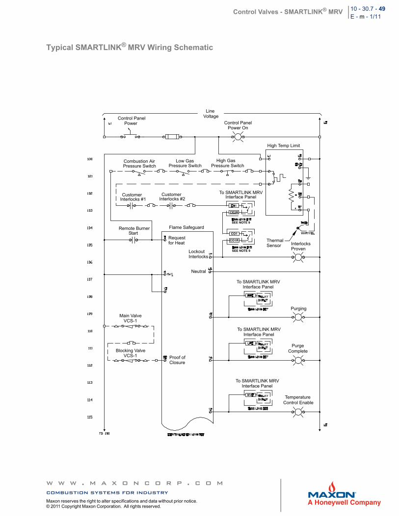
Control Valves - SMARTLINK® MRV 10 - 30.7 - 49E - m - 1/11
Typical SMARTLINK® MRV Wiring Schematic
CE2R
CO1
SEE NOTE 9
SEE NOTE 9
CO1R
Line VoltageControl Panel
Power Control PanelPower On
High Temp Limit
Combustion AirPressure Switch
Low GasPressure Switch
High GasPressure Switch
CustomerInterlocks #1
CustomerInterlocks #2
To SMARTLINK MRVInterface Panel
Remote BurnerStart
Flame Safeguard
Requestfor Heat Thermal
Sensor InterlocksProven
LockoutInterlocks
Neutral
To SMARTLINK MRVInterface Panel
Purging
Main ValveVCS-1
Blocking ValveVCS-1 Proof of
Closure
To SMARTLINK MRVInterface Panel
To SMARTLINK MRVInterface Panel
PurgeComplete
TemperatureControl Enable
w w w . m a x o n c o r p . c o mcombustion systems for industryMaxon reserves the right to alter specifications and data without prior notice. © 2011 Copyright Maxon Corporation. All rights reserved.
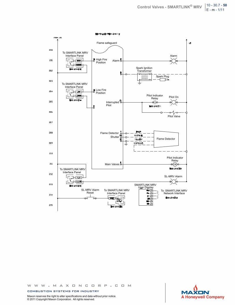
Control Valves - SMARTLINK® MRV 10 - 30.7 - 50E - m - 1/11
Flame safeguard
To SMARTLINK MRVInterface Panel
To SMARTLINK MRVInterface Panel
To SMARTLINK MRVInterface Panel
To SMARTLINK MRVInterface Panel
High FirePosition
Alarm
Alarm
Spark IgnitionTransformer
Spark Plug
Low FirePosition
InterruptedPilot
Pilot IndicatorRelay Pilot On
Pilot Valve
Flame Detector
Flame Detector
Shutter
Pilot IndicatorRelay
Main Valves
SL-MRV Alarm
SL-MRV AlarmReset
SMARTLINK MRVUser Display
To: SMARTLINK MRVNetwork Interface
w w w . m a x o n c o r p . c o mcombustion systems for industryMaxon reserves the right to alter specifications and data without prior notice. © 2011 Copyright Maxon Corporation. All rights reserved.
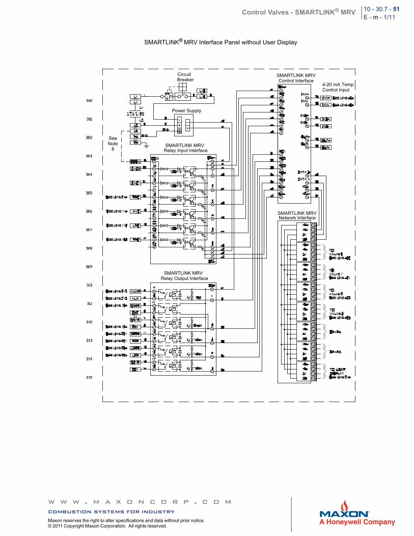
Control Valves - SMARTLINK® MRV 10 - 30.7 - 51E - m - 1/11
SMARTLINK® MRV Interface Panel without User Display
CircuitBreaker
SMARTLINK MRVControl Interface
4-20 mA TempControl Input
Power Supply
SMARTLINK MRVRelay Input Interface
SMARTLINK MRVNetwork Interface
SMARTLINK MRVRelay Output Interface
SeeNote
8
w w w . m a x o n c o r p . c o mcombustion systems for industryMaxon reserves the right to alter specifications and data without prior notice. © 2011 Copyright Maxon Corporation. All rights reserved.
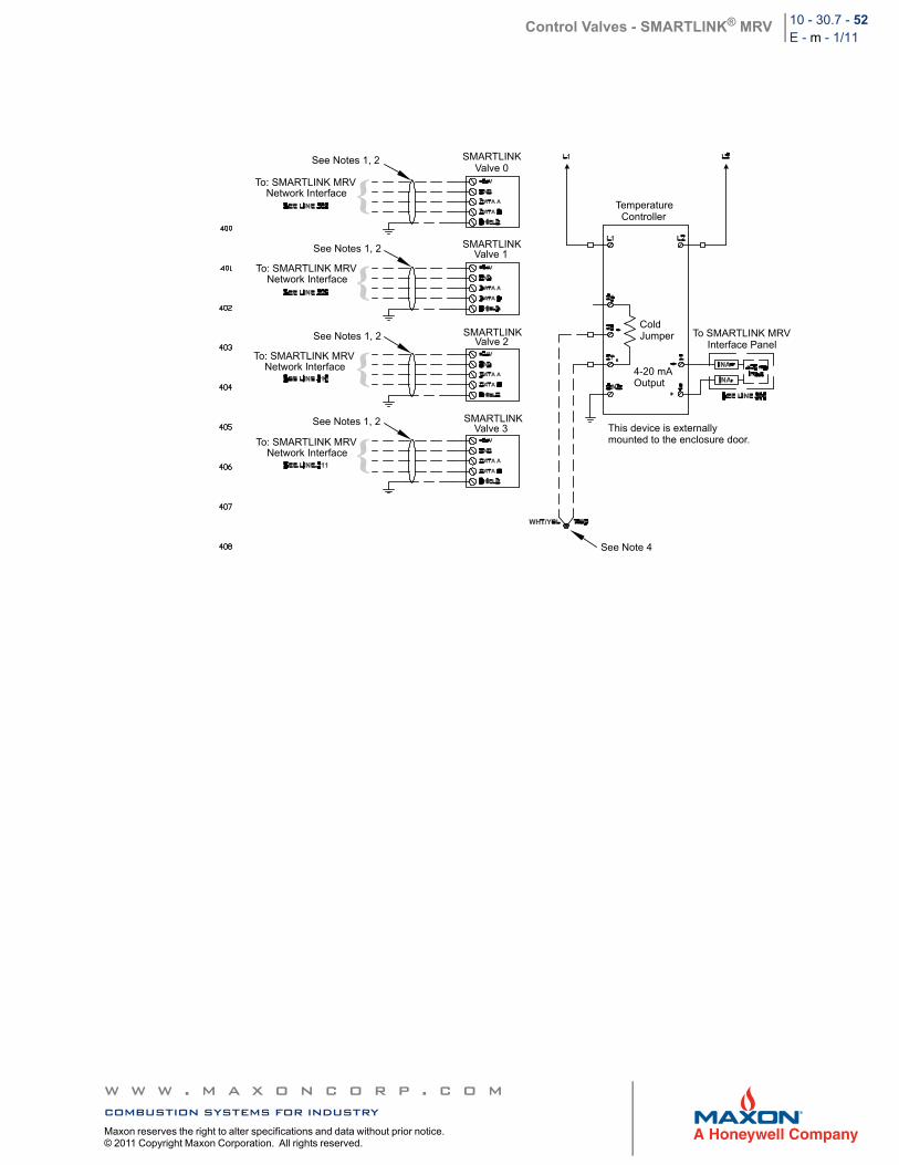
Control Valves - SMARTLINK® MRV 10 - 30.7 - 52E - m - 1/11
See Notes 1, 2 SMARTLINKValve 0
TemperatureController
To: SMARTLINK MRVNetwork Interface
To: SMARTLINK MRVNetwork Interface
To: SMARTLINK MRVNetwork Interface
To: SMARTLINK MRVNetwork Interface
SMARTLINK Valve 1
SMARTLINK Valve 2
SMARTLINKValve 3
ColdJumper To SMARTLINK MRV
Interface Panel
4-20 mAOutput
This device is externallymounted to the enclosure door.
See Note 4
See Notes 1, 2
See Notes 1, 2
See Notes 1, 2
w w w . m a x o n c o r p . c o mcombustion systems for industryMaxon reserves the right to alter specifications and data without prior notice. © 2011 Copyright Maxon Corporation. All rights reserved.
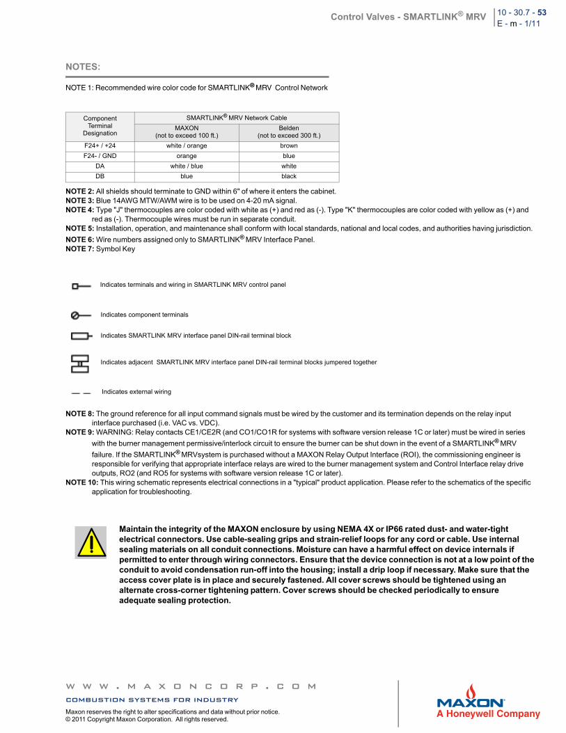
Control Valves - SMARTLINK® MRV 10 - 30.7 - 53E - m - 1/11
NOTES:
NOTE 1: Recommended wire color code for SMARTLINK® MRV Control Network
NOTE 2: All shields should terminate to GND within 6" of where it enters the cabinet.NOTE 3: Blue 14AWG MTW/AWM wire is to be used on 4-20 mA signal.NOTE 4: Type "J" thermocouples are color coded with white as (+) and red as (-). Type "K" thermocouples are color coded with yellow as (+) and
red as (-). Thermocouple wires must be run in separate conduit.NOTE 5: Installation, operation, and maintenance shall conform with local standards, national and local codes, and authorities having jurisdiction.
NOTE 6: Wire numbers assigned only to SMARTLINK® MRV Interface Panel.NOTE 7: Symbol Key
NOTE 8: The ground reference for all input command signals must be wired by the customer and its termination depends on the relay input interface purchased (i.e. VAC vs. VDC).
NOTE 9: WARNING: Relay contacts CE1/CE2R (and CO1/CO1R for systems with software version release 1C or later) must be wired in series
with the burner management permissive/interlock circuit to ensure the burner can be shut down in the event of a SMARTLINK® MRV
failure. If the SMARTLINK® MRVsystem is purchased without a MAXON Relay Output Interface (ROI), the commissioning engineer is responsible for verifying that appropriate interface relays are wired to the burner management system and Control Interface relay drive outputs, RO2 (and RO5 for systems with software version release 1C or later).
NOTE 10: This wiring schematic represents electrical connections in a "typical" product application. Please refer to the schematics of the specific application for troubleshooting.
ComponentTerminal
Designation
SMARTLINK® MRV Network Cable
MAXON(not to exceed 100 ft.)
Belden(not to exceed 300 ft.)
F24+ / +24 white / orange brown
F24- / GND orange blue
DA white / blue white
DB blue black
Maintain the integrity of the MAXON enclosure by using NEMA 4X or IP66 rated dust- and water-tight electrical connectors. Use cable-sealing grips and strain-relief loops for any cord or cable. Use internal sealing materials on all conduit connections. Moisture can have a harmful effect on device internals if permitted to enter through wiring connectors. Ensure that the device connection is not at a low point of the conduit to avoid condensation run-off into the housing; install a drip loop if necessary. Make sure that the access cover plate is in place and securely fastened. All cover screws should be tightened using an alternate cross-corner tightening pattern. Cover screws should be checked periodically to ensure adequate sealing protection.
Indicates terminals and wiring in SMARTLINK MRV control panel
Indicates component terminals
Indicates SMARTLINK MRV interface panel DIN-rail terminal block
Indicates adjacent SMARTLINK MRV interface panel DIN-rail terminal blocks jumpered together
Indicates external wiring
w w w . m a x o n c o r p . c o mcombustion systems for industryMaxon reserves the right to alter specifications and data without prior notice. © 2011 Copyright Maxon Corporation. All rights reserved.
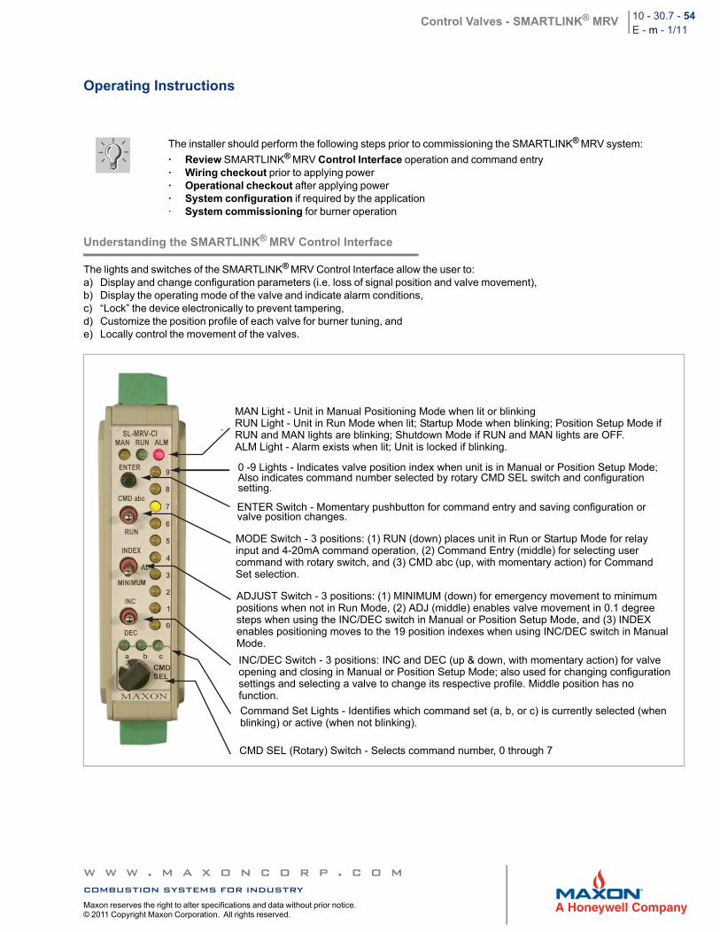
Control Valves - SMARTLINK® MRV 10 - 30.7 - 54E - m - 1/11
Operating Instructions
Understanding the SMARTLINK® MRV Control Interface
The lights and switches of the SMARTLINK® MRV Control Interface allow the user to: a) Display and change configuration parameters (i.e. loss of signal position and valve movement), b) Display the operating mode of the valve and indicate alarm conditions, c) “Lock” the device electronically to prevent tampering, d) Customize the position profile of each valve for burner tuning, and e) Locally control the movement of the valves.
The installer should perform the following steps prior to commissioning the SMARTLINK® MRV system:
· Review SMARTLINK® MRV Control Interface operation and command entry · Wiring checkout prior to applying power· Operational checkout after applying power· System configuration if required by the application· System commissioning for burner operation
MAN Light - Unit in Manual Positioning Mode when lit or blinkingRUN Light - Unit in Run Mode when lit; Startup Mode when blinking; Position Setup Mode ifRUN and MAN lights are blinking; Shutdown Mode if RUN and MAN lights are OFF.ALM Light - Alarm exists when lit; Unit is locked if blinking.
0 -9 Lights - Indicates valve position index when unit is in Manual or Position Setup Mode;Also indicates command number selected by rotary CMD SEL switch and configurationsetting.
ENTER Switch - Momentary pushbutton for command entry and saving configuration or valve position changes.
MODE Switch - 3 positions: (1) RUN (down) places unit in Run or Startup Mode for relayinput and 4-20mA command operation, (2) Command Entry (middle) for selecting usercommand with rotary switch, and (3) CMD abc (up, with momentary action) for CommandSet selection.
ADJUST Switch - 3 positions: (1) MINIMUM (down) for emergency movement to minimumpositions when not in Run Mode, (2) ADJ (middle) enables valve movement in 0.1 degreesteps when using the INC/DEC switch in Manual or Position Setup Mode, and (3) INDEXenables positioning moves to the 19 position indexes when using INC/DEC switch in ManualMode.
INC/DEC Switch - 3 positions: INC and DEC (up & down, with momentary action) for valveopening and closing in Manual or Position Setup Mode; also used for changing configurationsettings and selecting a valve to change its respective profile. Middle position has nofunction.
Command Set Lights - Identifies which command set (a, b, or c) is currently selected (whenblinking) or active (when not blinking).
CMD SEL (Rotary) Switch - Selects command number, 0 through 7
w w w . m a x o n c o r p . c o mcombustion systems for industryMaxon reserves the right to alter specifications and data without prior notice. © 2011 Copyright Maxon Corporation. All rights reserved.
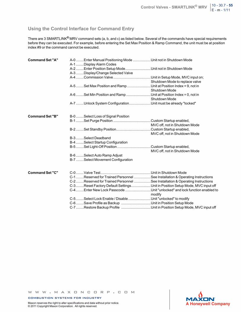
Control Valves - SMARTLINK® MRV 10 - 30.7 - 55E - m - 1/11
Using the Control Interface for Command Entry
There are 3 SMARTLINK® MRV command sets (a, b, and c) as listed below. Several of the commands have special requirements before they can be executed. For example, before entering the Set Max Position & Ramp Command, the unit must be at position index #9 or the command cannot be executed.
Command Set "A" A-0 ........Enter Manual Positioning Mode ..................Unit not in Shutdown ModeA-1 ........Display Alarm CodesA-2 ........Enter Position Setup Mode..........................Unit not in Shutdown ModeA-3 ........Display/Change Selected ValveA-4 ........Commission Valve ......................................Unit in Setup Mode, MVC input on;
Shutdown Mode to replace valveA-5 ........Set Max Position and Ramp ........................Unit at Position Index = 9, not in
Shutdown ModeA-6 ........Set Min Position and Ramp .........................Unit at Position Index = 0, not in
Shutdown ModeA-7 ........Unlock System Configuration......................Unit must be already "locked"
Command Set "B" B-0 ........Select Loss of Signal PositionB-1 ........Set Purge Position ......................................Custom Startup enabled,
MVC off, not in Shutdown ModeB-2 ........Set Standby Position...................................Custom Startup enabled,
MVC off, not in Shutdown ModeB-3 ........Select DeadbandB-4 ........Select Startup ConfigurationB-5 ........Set Light-Off Position ..................................Custom Startup enabled,
MVC off, not in Shutdown ModeB-6 ........Select Auto Ramp AdjustB-7 ........Select Movement Configuration
Command Set "C" C-0........Valve Test...................................................Unit in Shutdown ModeC-1........Reserved for Trained Personnel .................See Installation & Operating InstructionsC-2........Reserved for Trained Personnel .................See Installation & Operating InstructionsC-3........Reset Factory Default Settings....................Unit in Position Setup Mode, MVC input offC-4........Enter New Lock Passcode ..........................Unit "unlocked" and lock function enabled to
modifyC-5........Select Lock Enable / Disable.......................Unit "unlocked" to modifyC-6........Save Profile as Backup ..............................Unit in Position Setup ModeC-7........Restore Backup Profile ..............................Unit in Position Setup Mode, MVC input off
w w w . m a x o n c o r p . c o mcombustion systems for industryMaxon reserves the right to alter specifications and data without prior notice. © 2011 Copyright Maxon Corporation. All rights reserved.
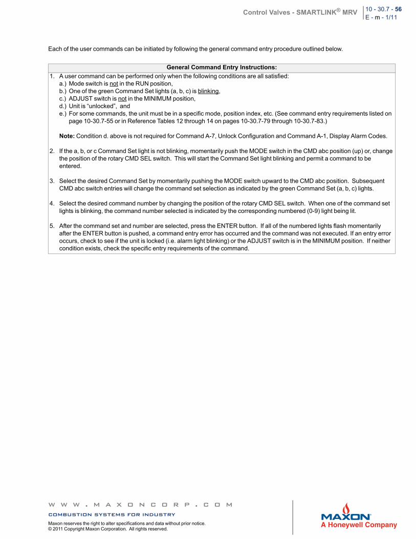
Control Valves - SMARTLINK® MRV 10 - 30.7 - 56E - m - 1/11
Each of the user commands can be initiated by following the general command entry procedure outlined below.
General Command Entry Instructions:
1. A user command can be performed only when the following conditions are all satisfied: a.) Mode switch is not in the RUN position, b.) One of the green Command Set lights (a, b, c) is blinking, c.) ADJUST switch is not in the MINIMUM position, d.) Unit is “unlocked”, ande.) For some commands, the unit must be in a specific mode, position index, etc. (See command entry requirements listed on
page 10-30.7-55 or in Reference Tables 12 through 14 on pages 10-30.7-79 through 10-30.7-83.)
Note: Condition d. above is not required for Command A-7, Unlock Configuration and Command A-1, Display Alarm Codes.
2. If the a, b, or c Command Set light is not blinking, momentarily push the MODE switch in the CMD abc position (up) or, change the position of the rotary CMD SEL switch. This will start the Command Set light blinking and permit a command to be entered.
3. Select the desired Command Set by momentarily pushing the MODE switch upward to the CMD abc position. Subsequent CMD abc switch entries will change the command set selection as indicated by the green Command Set (a, b, c) lights.
4. Select the desired command number by changing the position of the rotary CMD SEL switch. When one of the command set lights is blinking, the command number selected is indicated by the corresponding numbered (0-9) light being lit.
5. After the command set and number are selected, press the ENTER button. If all of the numbered lights flash momentarily after the ENTER button is pushed, a command entry error has occurred and the command was not executed. If an entry error occurs, check to see if the unit is locked (i.e. alarm light blinking) or the ADJUST switch is in the MINIMUM position. If neither condition exists, check the specific entry requirements of the command.
w w w . m a x o n c o r p . c o mcombustion systems for industryMaxon reserves the right to alter specifications and data without prior notice. © 2011 Copyright Maxon Corporation. All rights reserved.
Control Valves - SMARTLINK® MRV 10 - 30.7 - 57E - m - 1/11
User Display Operation
The optional SMARTLINK® MRV User Display simplifies commissioning and viewing system status with a back-lit, 4-line by 20-character, liquid crystal display (LCD). The User Display can be remotely mounted up to 1000 feet away from the Control Interface for remote commissioning and control room monitoring. Multiple displays can be connected to the system for both local and remote operation. All commissioning functions provided within the Control Interface can be performed with the User Display. However, the User Display provides the following functions in addition to the Control Interface commissioning and status capabilities:
• Alarm and fault condition text message display• Time-stamped history of 6 shutdown events• System and valve maintenance functions• Storing and viewing of up to 5 system profiles• Restoring system profile in replacement Control Interface
See Reference Table 15 for a summary of the Main Menu and Sub-Menu Command list. The five keys on the display are used as follows:
1) Press [MENU] key to move down Main Menu or Sub-Menu command list. 2) Press [BACK] key to move up Main Menu or Sub-Menu list. 3) Press [ENTER] to move from Main Menu command item to Sub-Menu list.4) Press [BACK] key to move from the top command item in a Sub-Menu list back to the Main Menu.5) Press [ENTER], [BACK] or [ARROW] keys to accomplish specific Sub-Menu tasks as prompted by the display.6) When on a Main Menu item, press [MENU] and [DOWN] keys simultaneously to reach last Main Menu item.7) When on a Main Menu item, press [BACK] and [UP] keys simultaneously to reach first main menu item.
Wiring Checkout
Before applying power to the SMARTLINK® MRV Interface Panel, Control Interface, or Valve Actuators, perform the following wiring checkout:
1) Verify that 120 VAC (or 230 VAC) power and burner management control signals are connected to the proper field wiring
terminals of the SMARTLINK® MRV Interface Panel.
2) If a factory-wired MAXON SMARTLINK® MRV Interface Panel was not purchased, verify that no 120 VAC (or 230 VAC) wiring is connected directly to any Control Interface or Valve Actuator terminal. The MRV Control Interface (and Valve Actuators) must be powered by a 24 volt DC source.
3) Verify the proper wire type and maximum wire length requirements are satisfied for all connections. 4) Verify network/power connection color codes are correct for the Valve Actuators. 5) Measure the resistance between earth ground at the enclosure of the Control Interface and each of the four signals wired to the
Valve Actuator: F24+ (Field 24VDC), F24- (Field 24VDC Common), DA (Data-A), and DB (Data-B). The resistance should indicate an open circuit (i.e., a resistance value greater than 10 Ohms). If an open circuit is not measured, damage or incorrect wiring of the control network cable exists and must be located.
6) Verify proper termination of shields for the 4-20 mA cables and the power/network cable between the SMARTLINK® MRV Interface Panel, Control Interface and Valve Actuators.
7) If a MAXON SMARTLINK® MRV Interface Panel is not provided, verify that all customer-provided output relays connected to RO1 through RO5 of the Control Interface have a 24 VDC coil rating and require less than 100 mA to turn on.
Refer to SMARTLINK® MRV Reference Tables 1 through 5 (pages 10-30.7-68 to 10-30.7-72) for all terminal definitions and wiring/shielding requirements.
w w w . m a x o n c o r p . c o mcombustion systems for industryMaxon reserves the right to alter specifications and data without prior notice. © 2011 Copyright Maxon Corporation. All rights reserved.
Control Valves - SMARTLINK® MRV 10 - 30.7 - 58E - m - 1/11
Operational Checkout
Apply power to the SMARTLINK® MRV System. If a SMARTLINK® MRV Interface Panel was purchased, switch the breaker located on the lower rail of the Interface Panel to the ON (or up) position. The breaker switch will power all system components
including the SMARTLINK® Valve Actuators. Perform the following operational checkout prior to attempting burner light-off and commissioning the system for burner operation:
1) Disable the burner system by turning the combustion blower off and manually turning off the pilot and main fuel supply.
2) Place the Mode switch of the Control Interface in its middle position. With all Valve Actuators wired, verify the Control Interface Alarm light is off and the Run light is blinking indicating the system is in the Startup Mode. If the Control Interface alarm light is on, see page 10-30.7-65 on troubleshooting and alarms, to determine the cause of the alarm and corrective actions.
3) Verify operation of each SMARTLINK® MRV relay output by using the procedures summarized in Table 10 (page 10-30.7-77). If a MAXON MRV Interface Panel is provided, the Relay Output Interface (ROI) is factory-wired to the Control Interface and a field wiring terminal block for easy access to the output contacts. The relay output terminals of the Control Interface are also referenced in Table 10 to assist in operational checkout of systems with customer-supplied relays or a PLC-based burner management system that controls burner startup (without the MAXON Relay Output Interface).
4) Turn on the combustion blower. Re-enable the burner management system but keep the pilot and main fuel supply turned off. Verify that all combustion system safety interlocks are satisfied.
5) Power cycle SMARTLINK® MRV and verify the relay input commands from the burner management system properly drive
SMARTLINK® MRV to its purge and light-off states. If a MAXON SMARTLINK® MRV Interface Panel is provided, the Relay Input Interface (RII) is factory-wired to the Control Interface and a field wiring terminal block. The lights of the Relay Input Interface indicate when each input command relay is energized and the 4-20 mA output (OUT-/OUT+ terminals) can be
measured by a current meter to verify SMARTLINK® MRV has responded to the input command. When the burner management system (or flame safety) issues a Purge Position Command, the PPC terminal of the Interface Panel is energized and the Relay Input Interface (terminal #6) outputs a voltage greater than 22 VDC to the Control Interface input terminal RI1 (Relay Input #1). When a Light-Off Position Command is issued, the LPC terminal of the Interface Panel is energized and the Relay Input Interface (terminal #5) outputs a voltage greater than 5 VDC to the Control Interface input terminal RI2 (Relay Input
#2). The following 4-20 mA output currents can be measured for each of the following SMARTLINK® MRV states: 1 mA= Standby Positions; 2 mA = Purge Positions; 3 mA = Light-Off Positions.
w w w . m a x o n c o r p . c o mcombustion systems for industryMaxon reserves the right to alter specifications and data without prior notice. © 2011 Copyright Maxon Corporation. All rights reserved.
Control Valves - SMARTLINK® MRV 10 - 30.7 - 59E - m - 1/11
System Configuration
There are 7 SMARTLINK® configuration settings that can be changed through execution of the commands listed below. Detailed
explanations of each setting appear in Reference Table 11: SMARTLINK® MRV System Configuration Summary (page 10-30.7-78).
Command Name Command Number Factory DefaultSelect Loss of Signal (LOS) Position B-0 Setting #0: Position Index 0 (Minimum)Select Control Deadband B-3 Setting #2: 0.06% DeadbandSelect Startup Configuration B-4 Setting #0: Default StartupSelect Auto Ramp Adjust B-6 Setting #1: Auto Ramp ONSelect Movement Configuration B-7 Setting #1: Medium Speed (~40 seconds)Enter New Lock Passcode C-4 Default Passcode: 0, 0, 0, 0Select Lock Enable/Disable C-5 Setting # 0: Lock Disable
Review the factory default settings before changing any of the system configuration settings. In many applications, modification of the default settings is not necessary. If a setting does need to be changed, follow the procedure below.
Procedure for Changing a System Configuration Setting:
a) Select and enter the required system configuration command.
b) After the command is entered, one of the numbered (0-9) lights will be on, indicating the current configuration setting. (For example: If the lock configuration is set to #0, Lock Disable, the 0 light will be solidly lit after Command C-5, Lock Enable/Disable, is entered successfully.)
c) Select the desired configuration setting by using the INC/DEC switch. As the INC/DEC switch is momentarily pushed up or down, the selected setting changes as indicated by turning on the corresponding numbered (0-9) light.
d) Push the ENTER button after the desired configuration setting is selected. The numbered light (i.e. selected configuration) that is lit will momentarily turn off indicating the command is complete and the configuration setting is saved.
e) To confirm the correct setting is saved, re-enter the command and verify the new setting by the numbered (0-9) light indication.
w w w . m a x o n c o r p . c o mcombustion systems for industryMaxon reserves the right to alter specifications and data without prior notice. © 2011 Copyright Maxon Corporation. All rights reserved.
Control Valves - SMARTLINK® MRV 10 - 30.7 - 60E - m - 1/11
10-Point System Commissioning
The SMARTLINK® MRV Control Interface is shipped with configuration settings that support a 10-point commissioning procedure as described on the following page. Specifically, the Auto Ramp ON configuration is selected as the default setting so that fuel valve adjustment is needed for only 10 position indexes (0, 1, 2…9). The 9 intermediate position indexes (0.5, 1.5, 2.5, etc.) are automatically set to positions mid-way between the 10 integer position indexes, 0 through 9. In addition, the Default Startup Configuration sets the standby, purge, and light-off positions to the same values as those established for Index 0 (minimum), Index 9 (maximum), and Index 0 (minimum), respectively. See Reference Table 11 for a detailed description of these configuration settings.
When SMARTLINK® MRV is in the Position Setup Mode for commissioning, the ADJUST switch can be pushed to the MINIMUM position (down). This action will immediately move the valves synchronously to position index #0, the minimum position. This feature provides a method (during commissioning when the user’s temperature controller is not in automatic mode) to quickly ramp the burner back to low fire if a process or combustion condition warrants an immediate burner firing rate change.
An optional User Display with a 4-line by 20 character LCD can also be used for SMARTLINK® MRV commissioning instead of the Control Interface switches and lights. The commissioning procedure using the User Display is described on page 10-30.7-62. See Reference Table 15 on page 10-30.7-84 for a description of User Display key operation and commands, as well as a numbered menu structure.
19-Point System Commissioning
There are combustion applications that require burner adjustment at more than 10 points throughout the firing range to meet emissions or fuel efficiency requirements. For these applications, the Auto Ramp configuration should be OFF, setting #0. With Auto Ramp OFF, adjustment of each fuel valve at all 19 position indexes (0, 0.5, 1.0, 1.5…8.5, and 9) is now required and no automatic “smoothing” is performed on points adjacent to the position index being adjusted. The procedure for adjusting all 19 points is identical to the 10-point procedure described above with the following exceptions:
1.) In step g of the 10-Point Commissioning (using the Control Interface) procedure on page 10-30.7-61, execute Command B-6 to ensure the auto ramp function is OFF, setting #0. In step g of the 10-Point Commissioning (using the User Display), go to Main Menu 9 (Set Configuration) and use the ARROW up key until the auto ramp configuration can be verified.
2.) In step h, the firing rate should be adjusted at 0.5-position index steps instead of every whole integer position index.
In some applications, it may also be desirable to adjust positions at all 19 points of the air valve(s) in order to provide a linear flow characteristic. The same 19-point adjustment process used for the fuel valves would be performed for the air valve(s) instead of the 2-point linear position setup using Commands A-5 and A-6 (described in steps c through e).
Custom Start-up Positions
The Custom Startup Configuration is intended for burners or applications that require standby, light-off, or purge positions that are independent of the burner’s normal operating valve position curves.
To enable this function using the Control Interface, execute Command B-4, Select Startup Configuration. Use the INC/DEC switch to select setting #1 (Custom Startup) and press the ENTER switch to save the configuration setting if it has been changed. Command B-1 (Set Purge Positions), Command B-2 (Set Standby Positions), and Command B-5 (Set Light-Off Positions) can now be executed to set custom valve positions during startup. See Reference Table 13 for a more detailed explanation of how to use these commands.
These custom startup adjustment commands can also be executed from the User Display using Main Menu 9 to select the Startup Configuration item (using the ARROW keys) and Sub-Menu 9.1 to change (ARROW keys) and save (ENTER key) the setting. See Reference Table 15 (page 10-30.7-84) for the User Display command menu structure.
w w w . m a x o n c o r p . c o mcombustion systems for industryMaxon reserves the right to alter specifications and data without prior notice. © 2011 Copyright Maxon Corporation. All rights reserved.
Control Valves - SMARTLINK® MRV 10 - 30.7 - 61E - m - 1/11
Commissioning Procedure with Control Interface
SMARTLINK® MRV 10-Point Commissioning Procedure with Control Interface
a) Disable burner light-off by turning off the burner management system or disabling a combustion permissive so that interlocks cannot be proven. Turn on the combustion blower.
b) Execute Command A-0, Enter Manual Mode. With the ADJUST switch in the up (INDEX) position, push the INC/DEC switch momentarily to advance the firing rate to position index #9.
c) Execute Command A-3 and select the SMARTLINK® Air Valve Actuator’s number by using the INC/DEC switch to light the desired valve number. (The number of the Air Valve Actuator is on the unit’s label.) Execute Command A-5, Set Max Posi-tion & Ramp, and adjust the air valve maximum position to satisfy the pressure/flow requirements of the burner. When this command is executed, both the yellow and green run lights will be flashing indicating the system is in Position Setup Mode.
d) With the ADJUST switch in the middle (ADJ) position, push the INC/DEC switch up or down to change the valve position. Each push of the INC/DEC switch moves the valve 0.1 degrees. If the switch is held in the up or down position for more than 3 seconds, the valve will move in 0.5 degree steps up to a total travel of 8 degrees from the stored valve position. (All the numbered lights will momentarily flash when this 8 degree limit or the maximum valve travel is reached.) After moving the valve to the desired position, press the ENTER button to save the position setting. The command ‘a’ light will momentarily turn off and then back on (solid) after the position is saved. (Any numbered light that was blinking will also momentarily turn off and then resume blinking after the position is saved.) Record the valve position feedback in milliamps (mA) or percent that is present on the OUT+/- terminals of the Control Interface.
e) Execute Command A-0, Enter Manual Mode, again and move to position index #0. Execute Command A-6, Set Min Position & Ramp, and adjust the minimum air valve position in the same manner as the maximum position was adjusted in step d.
f) Repeat steps b through e for all other air valves installed. SMARTLINK® MRV is shipped with factory default minimum and maximum valve positions of 6.0 and 60.0 degrees, respectively.
g) Momentarily set the mode switch in the RUN position, re-enable the burner management system and light the burner. Exe-cute Command B-6 to ensure the auto ramp function is set to #1, ON. Select the fuel valve for adjustment using Command A-3 and then execute Command A-6, Set Min Position and Ramp. This command permits adjustment of the minimum posi-tion and then creates a linear ramp to the current maximum position. The system is placed in Position Setup Mode, indicated by the flashing of both the yellow (MANUAL) and green (RUN) lights. With the ADJUST switch in the middle position, trim the fuel valve's position at index #0 (minimum) based on burner pressure or flow measurement equipment as performed in step d above. Repeat this step to adjust the minimum and linear position ramp for all other fuel valves in the system.
h) After adjusting index #0 (and forcing a linear position ramp) for the fuel valve, place the adjust switch in the INDEX (up) posi-tion and execute Command A-2 (Enter Position Setup Mode). Move the MRV firing rate to the next whole integer position index (index #1) by momentarily pressing the INC/DEC switch until the desired index number is turned ON. Move the ADJUST switch back to the middle (ADJ) position. Use the INC/DEC switch to adjust valve position based on burner pres-sure or flow measurement and press ENTER to save the profile to memory as described in step d above. Repeat this adjust-ment procedure for each whole integer index up to and including index #9 (maximum). If necessary, make gas pressure regulator adjustments at index #9 and then work back down through the lower indexes making adjustments as required.
i) After the last adjustment is made in Position Setup Mode, use the INC/DEC switch to move to position index #9 (or the high-est position index adjusted for all valves) with the ADJUST switch in the INDEX (up) position. Select the air valve using Com-
mand A-3 and then execute Command A-4, Commission Valve. Repeat this step for each installed SMARTLINK® MRV valve actuator. The commission command stores the selected valves current position index as its maximum allowable position index while in RUN mode (i.e. under 4-20 mA firing rate control). If one valve has a "maximum run index" less than the other commissioned valves, the system will not modulate above the lowest run index. The system will also not modulate in RUN mode if any valve is not commissioned.
j) Record in the SMARTLINK® MRV commissioning table (Table 16, page 10-30.7-86 and 10-30.7-87) the position of each valve and pressure (or flow) at each index. Execute Command C-6 to save the profile as a backup. Move the MODE switch to the RUN position and set the user’s temperature controller to AUTO.
w w w . m a x o n c o r p . c o mcombustion systems for industryMaxon reserves the right to alter specifications and data without prior notice. © 2011 Copyright Maxon Corporation. All rights reserved.
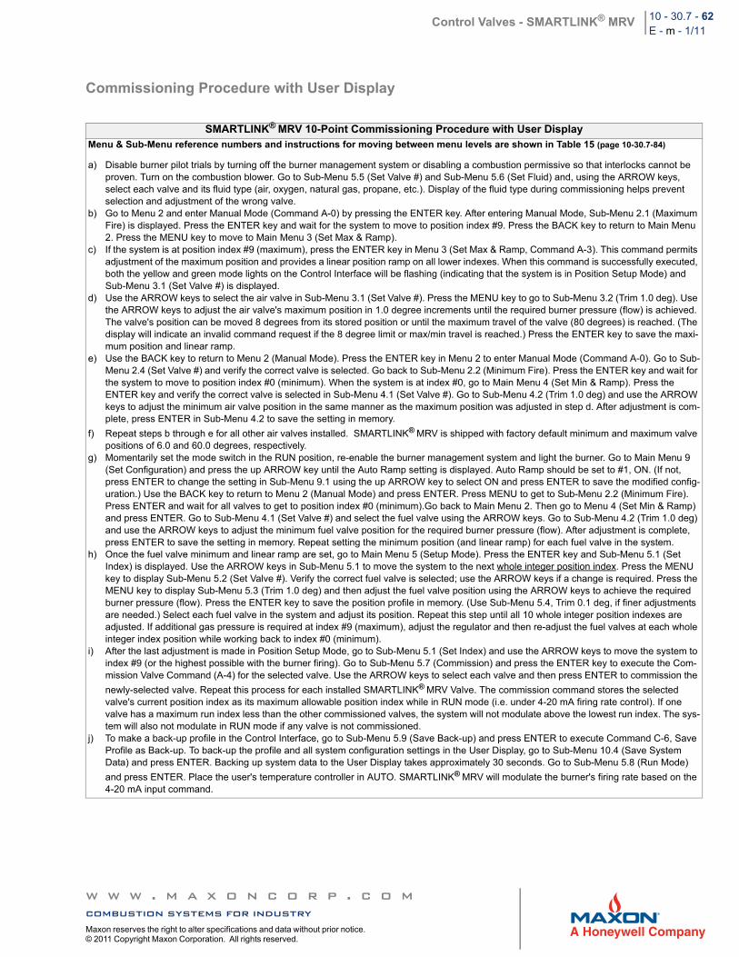
Control Valves - SMARTLINK® MRV 10 - 30.7 - 62E - m - 1/11
Commissioning Procedure with User Display
SMARTLINK® MRV 10-Point Commissioning Procedure with User DisplayMenu & Sub-Menu reference numbers and instructions for moving between menu levels are shown in Table 15 (page 10-30.7-84)
a) Disable burner pilot trials by turning off the burner management system or disabling a combustion permissive so that interlocks cannot be proven. Turn on the combustion blower. Go to Sub-Menu 5.5 (Set Valve #) and Sub-Menu 5.6 (Set Fluid) and, using the ARROW keys, select each valve and its fluid type (air, oxygen, natural gas, propane, etc.). Display of the fluid type during commissioning helps prevent selection and adjustment of the wrong valve.
b) Go to Menu 2 and enter Manual Mode (Command A-0) by pressing the ENTER key. After entering Manual Mode, Sub-Menu 2.1 (Maximum Fire) is displayed. Press the ENTER key and wait for the system to move to position index #9. Press the BACK key to return to Main Menu 2. Press the MENU key to move to Main Menu 3 (Set Max & Ramp).
c) If the system is at position index #9 (maximum), press the ENTER key in Menu 3 (Set Max & Ramp, Command A-3). This command permits adjustment of the maximum position and provides a linear position ramp on all lower indexes. When this command is successfully executed, both the yellow and green mode lights on the Control Interface will be flashing (indicating that the system is in Position Setup Mode) and Sub-Menu 3.1 (Set Valve #) is displayed.
d) Use the ARROW keys to select the air valve in Sub-Menu 3.1 (Set Valve #). Press the MENU key to go to Sub-Menu 3.2 (Trim 1.0 deg). Use the ARROW keys to adjust the air valve's maximum position in 1.0 degree increments until the required burner pressure (flow) is achieved. The valve's position can be moved 8 degrees from its stored position or until the maximum travel of the valve (80 degrees) is reached. (The display will indicate an invalid command request if the 8 degree limit or max/min travel is reached.) Press the ENTER key to save the maxi-mum position and linear ramp.
e) Use the BACK key to return to Menu 2 (Manual Mode). Press the ENTER key in Menu 2 to enter Manual Mode (Command A-0). Go to Sub-Menu 2.4 (Set Valve #) and verify the correct valve is selected. Go back to Sub-Menu 2.2 (Minimum Fire). Press the ENTER key and wait for the system to move to position index #0 (minimum). When the system is at index #0, go to Main Menu 4 (Set Min & Ramp). Press the ENTER key and verify the correct valve is selected in Sub-Menu 4.1 (Set Valve #). Go to Sub-Menu 4.2 (Trim 1.0 deg) and use the ARROW keys to adjust the minimum air valve position in the same manner as the maximum position was adjusted in step d. After adjustment is com-plete, press ENTER in Sub-Menu 4.2 to save the setting in memory.
f) Repeat steps b through e for all other air valves installed. SMARTLINK® MRV is shipped with factory default minimum and maximum valve positions of 6.0 and 60.0 degrees, respectively.
g) Momentarily set the mode switch in the RUN position, re-enable the burner management system and light the burner. Go to Main Menu 9 (Set Configuration) and press the up ARROW key until the Auto Ramp setting is displayed. Auto Ramp should be set to #1, ON. (If not, press ENTER to change the setting in Sub-Menu 9.1 using the up ARROW key to select ON and press ENTER to save the modified config-uration.) Use the BACK key to return to Menu 2 (Manual Mode) and press ENTER. Press MENU to get to Sub-Menu 2.2 (Minimum Fire). Press ENTER and wait for all valves to get to position index #0 (minimum).Go back to Main Menu 2. Then go to Menu 4 (Set Min & Ramp) and press ENTER. Go to Sub-Menu 4.1 (Set Valve #) and select the fuel valve using the ARROW keys. Go to Sub-Menu 4.2 (Trim 1.0 deg) and use the ARROW keys to adjust the minimum fuel valve position for the required burner pressure (flow). After adjustment is complete, press ENTER to save the setting in memory. Repeat setting the minimum position (and linear ramp) for each fuel valve in the system.
h) Once the fuel valve minimum and linear ramp are set, go to Main Menu 5 (Setup Mode). Press the ENTER key and Sub-Menu 5.1 (Set Index) is displayed. Use the ARROW keys in Sub-Menu 5.1 to move the system to the next whole integer position index. Press the MENU key to display Sub-Menu 5.2 (Set Valve #). Verify the correct fuel valve is selected; use the ARROW keys if a change is required. Press the MENU key to display Sub-Menu 5.3 (Trim 1.0 deg) and then adjust the fuel valve position using the ARROW keys to achieve the required burner pressure (flow). Press the ENTER key to save the position profile in memory. (Use Sub-Menu 5.4, Trim 0.1 deg, if finer adjustments are needed.) Select each fuel valve in the system and adjust its position. Repeat this step until all 10 whole integer position indexes are adjusted. If additional gas pressure is required at index #9 (maximum), adjust the regulator and then re-adjust the fuel valves at each whole integer index position while working back to index #0 (minimum).
i) After the last adjustment is made in Position Setup Mode, go to Sub-Menu 5.1 (Set Index) and use the ARROW keys to move the system to index #9 (or the highest possible with the burner firing). Go to Sub-Menu 5.7 (Commission) and press the ENTER key to execute the Com-mission Valve Command (A-4) for the selected valve. Use the ARROW keys to select each valve and then press ENTER to commission the
newly-selected valve. Repeat this process for each installed SMARTLINK® MRV Valve. The commission command stores the selected valve's current position index as its maximum allowable position index while in RUN mode (i.e. under 4-20 mA firing rate control). If one valve has a maximum run index less than the other commissioned valves, the system will not modulate above the lowest run index. The sys-tem will also not modulate in RUN mode if any valve is not commissioned.
j) To make a back-up profile in the Control Interface, go to Sub-Menu 5.9 (Save Back-up) and press ENTER to execute Command C-6, Save Profile as Back-up. To back-up the profile and all system configuration settings in the User Display, go to Sub-Menu 10.4 (Save System Data) and press ENTER. Backing up system data to the User Display takes approximately 30 seconds. Go to Sub-Menu 5.8 (Run Mode)
and press ENTER. Place the user's temperature controller in AUTO. SMARTLINK® MRV will modulate the burner's firing rate based on the 4-20 mA input command.
w w w . m a x o n c o r p . c o mcombustion systems for industryMaxon reserves the right to alter specifications and data without prior notice. © 2011 Copyright Maxon Corporation. All rights reserved.
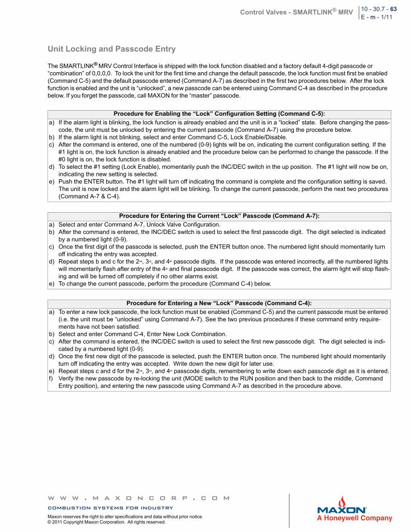
Control Valves - SMARTLINK® MRV 10 - 30.7 - 63E - m - 1/11
Unit Locking and Passcode Entry
The SMARTLINK® MRV Control Interface is shipped with the lock function disabled and a factory default 4-digit passcode or “combination” of 0,0,0,0. To lock the unit for the first time and change the default passcode, the lock function must first be enabled (Command C-5) and the default passcode entered (Command A-7) as described in the first two procedures below. After the lock function is enabled and the unit is “unlocked”, a new passcode can be entered using Command C-4 as described in the procedure below. If you forget the passcode, call MAXON for the “master” passcode.
Procedure for Enabling the “Lock” Configuration Setting (Command C-5):
a) If the alarm light is blinking, the lock function is already enabled and the unit is in a “locked” state. Before changing the pass-code, the unit must be unlocked by entering the current passcode (Command A-7) using the procedure below.
b) If the alarm light is not blinking, select and enter Command C-5, Lock Enable/Disable. c) After the command is entered, one of the numbered (0-9) lights will be on, indicating the current configuration setting. If the
#1 light is on, the lock function is already enabled and the procedure below can be performed to change the passcode. If the #0 light is on, the lock function is disabled.
d) To select the #1 setting (Lock Enable), momentarily push the INC/DEC switch in the up position. The #1 light will now be on, indicating the new setting is selected.
e) Push the ENTER button. The #1 light will turn off indicating the command is complete and the configuration setting is saved. The unit is now locked and the alarm light will be blinking. To change the current passcode, perform the next two procedures (Command A-7 & C-4).
Procedure for Entering the Current “Lock” Passcode (Command A-7):
a) Select and enter Command A-7, Unlock Valve Configuration.b) After the command is entered, the INC/DEC switch is used to select the first passcode digit. The digit selected is indicated
by a numbered light (0-9).c) Once the first digit of the passcode is selected, push the ENTER button once. The numbered light should momentarily turn
off indicating the entry was accepted. d) Repeat steps b and c for the 2nd, 3rd, and 4th passcode digits. If the passcode was entered incorrectly, all the numbered lights
will momentarily flash after entry of the 4th and final passcode digit. If the passcode was correct, the alarm light will stop flash-ing and will be turned off completely if no other alarms exist.
e) To change the current passcode, perform the procedure (Command C-4) below.
Procedure for Entering a New “Lock” Passcode (Command C-4):
a) To enter a new lock passcode, the lock function must be enabled (Command C-5) and the current passcode must be entered (i.e. the unit must be “unlocked” using Command A-7). See the two previous procedures if these command entry require-ments have not been satisfied.
b) Select and enter Command C-4, Enter New Lock Combination.c) After the command is entered, the INC/DEC switch is used to select the first new passcode digit. The digit selected is indi-
cated by a numbered light (0-9).d) Once the first new digit of the passcode is selected, push the ENTER button once. The numbered light should momentarily
turn off indicating the entry was accepted. Write down the new digit for later use.e) Repeat steps c and d for the 2nd, 3rd, and 4th passcode digits, remembering to write down each passcode digit as it is entered.f) Verify the new passcode by re-locking the unit (MODE switch to the RUN position and then back to the middle, Command
Entry position), and entering the new passcode using Command A-7 as described in the procedure above.
w w w . m a x o n c o r p . c o mcombustion systems for industryMaxon reserves the right to alter specifications and data without prior notice. © 2011 Copyright Maxon Corporation. All rights reserved.
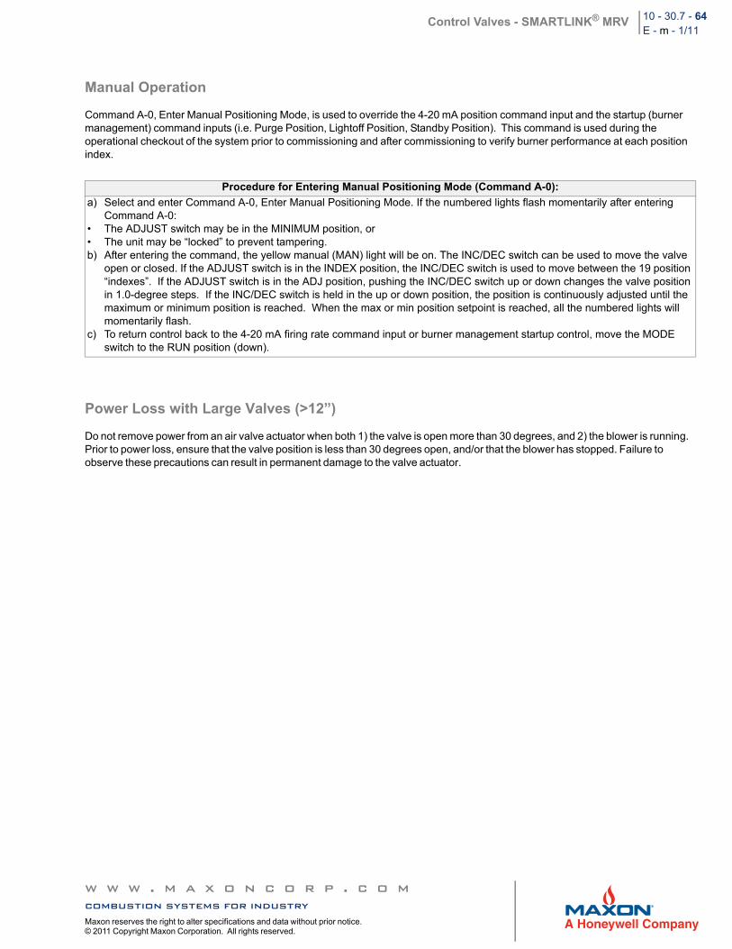
Control Valves - SMARTLINK® MRV 10 - 30.7 - 64E - m - 1/11
Manual Operation
Command A-0, Enter Manual Positioning Mode, is used to override the 4-20 mA position command input and the startup (burner management) command inputs (i.e. Purge Position, Lightoff Position, Standby Position). This command is used during the operational checkout of the system prior to commissioning and after commissioning to verify burner performance at each position index.
Power Loss with Large Valves (>12”)
Do not remove power from an air valve actuator when both 1) the valve is open more than 30 degrees, and 2) the blower is running. Prior to power loss, ensure that the valve position is less than 30 degrees open, and/or that the blower has stopped. Failure to observe these precautions can result in permanent damage to the valve actuator.
Procedure for Entering Manual Positioning Mode (Command A-0):
a) Select and enter Command A-0, Enter Manual Positioning Mode. If the numbered lights flash momentarily after entering Command A-0:
• The ADJUST switch may be in the MINIMUM position, or• The unit may be “locked” to prevent tampering.b) After entering the command, the yellow manual (MAN) light will be on. The INC/DEC switch can be used to move the valve
open or closed. If the ADJUST switch is in the INDEX position, the INC/DEC switch is used to move between the 19 position “indexes”. If the ADJUST switch is in the ADJ position, pushing the INC/DEC switch up or down changes the valve position in 1.0-degree steps. If the INC/DEC switch is held in the up or down position, the position is continuously adjusted until the maximum or minimum position is reached. When the max or min position setpoint is reached, all the numbered lights will momentarily flash.
c) To return control back to the 4-20 mA firing rate command input or burner management startup control, move the MODE switch to the RUN position (down).
w w w . m a x o n c o r p . c o mcombustion systems for industryMaxon reserves the right to alter specifications and data without prior notice. © 2011 Copyright Maxon Corporation. All rights reserved.
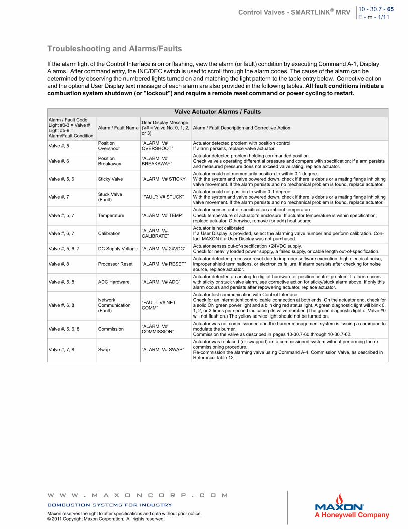
Control Valves - SMARTLINK® MRV 10 - 30.7 - 65E - m - 1/11
Troubleshooting and Alarms/Faults
If the alarm light of the Control Interface is on or flashing, view the alarm (or fault) condition by executing Command A-1, Display Alarms. After command entry, the INC/DEC switch is used to scroll through the alarm codes. The cause of the alarm can be determined by observing the numbered lights turned on and matching the light pattern to the table entry below. Corrective action and the optional User Display text message of each alarm are also provided in the following tables. All fault conditions initiate a combustion system shutdown (or "lockout") and require a remote reset command or power cycling to restart.
Valve Actuator Alarms / FaultsAlarm / Fault CodeLight #0-3 = Valve #Light #5-9 =Alarm/Fault Condition
Alarm / Fault NameUser Display Message(V# = Valve No. 0, 1, 2, or 3)
Alarm / Fault Description and Corrective Action
Valve #, 5PositionOvershoot
“ALARM: V# OVERSHOOT”
Actuator detected problem with position control.If alarm persists, replace valve actuator.
Valve #, 6PositionBreakaway
“ALARM: V#BREAKAWAY”
Actuator detected problem holding commanded position.Check valve’s operating differential pressure and compare with specification; if alarm persists and measured pressure does not exceed valve rating, replace actuator.
Valve #, 5, 6 Sticky Valve “ALARM: V# STICKYActuator could not momentarily position to within 0.1 degree.With the system and valve powered down, check if there is debris or a mating flange inhibiting valve movement. If the alarm persists and no mechanical problem is found, replace actuator.
Valve #, 7Stuck Valve(Fault)
“FAULT: V# STUCK”Actuator could not position to within 0.1 degree.With the system and valve powered down, check if there is debris or a mating flange inhibiting valve movement. If the alarm persists and no mechanical problem is found, replace actuator.
Valve #, 5, 7 Temperature “ALARM: V# TEMP”Actuator senses out-of-specification ambient temperature.Check temperature of actuator’s enclosure. If actuator temperature is within specification, replace actuator. Otherwise, remove (or add) heat source.
Valve #, 6, 7 Calibration“ALARM: V#CALIBRATE”
Actuator is not calibrated.If a User Display is provided, select the alarming valve number and perform calibration. Con-tact MAXON if a User Display was not purchased.
Valve #, 5, 6, 7 DC Supply Voltage “ALARM: V# 24VDC”Actuator senses out-of-specification +24VDC supply.Check for heavily loaded power supply, a failed supply, or cable length out-of-specification.
Valve #, 8 Processor Reset “ALARM: V# RESET”Actuator detected processor reset due to improper software execution, high electrical noise, improper shield terminations, or electronics failure. If alarm persists after checking for noise source, replace actuator.
Valve #, 5, 8 ADC Hardware “ALARM: V# ADC”Actuator detected an analog-to-digital hardware or position control problem. If alarm occurs with sticky or stuck valve alarm, see corrective action for sticky/stuck alarm above. If only this alarm occurs and persists after repowering actuator, replace actuator.
Valve #, 6, 8Network Communication (Fault)
“FAULT: V# NET COMM”
Actuator lost communication with Control Interface.Check for an intermittent control cable connection at both ends. On the actuator end, check for a solid ON green power light and a blinking red status light. A green diagnostic light will blink 0, 1, 2, or 3 times per second indicating its valve number. (The green diagnostic light of Valve #0 will not flash on.) The yellow service light should not be turned on.
Valve #, 5, 6, 8 Commission“ALARM: V# COMMISSION”
Actuator was not commissioned and the burner management system is issuing a command to modulate the burner.Commission the valve as described in pages 10-30.7-60 through 10-30.7-62.
Valve #, 7, 8 Swap “ALARM: V# SWAP”
Actuator was replaced (or swapped) on a commissioned system without performing the re-commissioning procedure.Re-commission the alarming valve using Command A-4, Commission Valve, as described in Reference Table 12.
w w w . m a x o n c o r p . c o mcombustion systems for industryMaxon reserves the right to alter specifications and data without prior notice. © 2011 Copyright Maxon Corporation. All rights reserved.
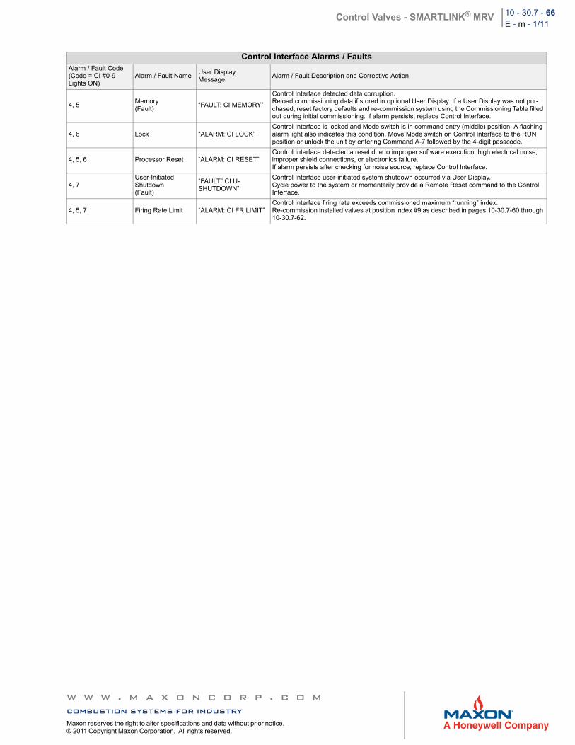
Control Valves - SMARTLINK® MRV 10 - 30.7 - 66E - m - 1/11
Control Interface Alarms / FaultsAlarm / Fault Code(Code = CI #0-9Lights ON)
Alarm / Fault NameUser Display Message
Alarm / Fault Description and Corrective Action
4, 5Memory (Fault)
“FAULT: CI MEMORY”
Control Interface detected data corruption.Reload commissioning data if stored in optional User Display. If a User Display was not pur-chased, reset factory defaults and re-commission system using the Commissioning Table filled out during initial commissioning. If alarm persists, replace Control Interface.
4, 6 Lock “ALARM: CI LOCK”Control Interface is locked and Mode switch is in command entry (middle) position. A flashing alarm light also indicates this condition. Move Mode switch on Control Interface to the RUN position or unlock the unit by entering Command A-7 followed by the 4-digit passcode.
4, 5, 6 Processor Reset “ALARM: CI RESET”Control Interface detected a reset due to improper software execution, high electrical noise, improper shield connections, or electronics failure.If alarm persists after checking for noise source, replace Control Interface.
4, 7User-Initiated Shutdown(Fault)
“FAULT” CI U-SHUTDOWN”
Control Interface user-initiated system shutdown occurred via User Display.Cycle power to the system or momentarily provide a Remote Reset command to the Control Interface.
4, 5, 7 Firing Rate Limit “ALARM: CI FR LIMIT”Control Interface firing rate exceeds commissioned maximum “running” index.Re-commission installed valves at position index #9 as described in pages 10-30.7-60 through 10-30.7-62.
w w w . m a x o n c o r p . c o mcombustion systems for industryMaxon reserves the right to alter specifications and data without prior notice. © 2011 Copyright Maxon Corporation. All rights reserved.
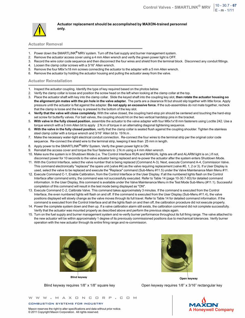
Control Valves - SMARTLINK® MRV 10 - 30.7 - 67E - m - 1/11
Actuator Removal
1. Power down the SMARTLINK® MRV system. Turn off the fuel supply and burner management system. 2. Remove the actuator access cover using a 4 mm Allen wrench and verify the green power light is OFF.3. Record the wire color code sequence and then disconnect the four wires and shield from the terminal block. Disconnect any conduit fittings.4. Loosen the clamp collar screws with a 3/16” Allen wrench.5. Remove the four M6x1x18 mm screws connecting the actuator to the adapter with a 5 mm Allen wrench.6. Remove the actuator by holding the actuator housing and pulling the actuator away from the valve.
Actuator Reinstallation
1. Inspect the actuator coupling. Identify the type of key required based on the photos below.2. Verify the clamp collar is loose and position the screw head on the left when looking at the clamp collar at the top.3. Place the actuator shaft with key into the clamp collar. Slide the keyed shaft into the coupling key slot, then rotate the actuator housing so
the alignment pin mates with the pin hole in the valve adapter. The parts are a clearance fit but should slip together with little force. Apply pressure until the actuator is flat against the adapter. Do not apply an excessive force. If the sub-assemblies do not mate together, recheck that the clamp is loose and the key is pressed to the bottom of the key slot.
4. Verify that the valve will close completely. With the valve closed, the coupling hard-stop pin should be centered and touching the hard-stop set screw for butterfly valves. For ball valves, the coupling should hit on the two vertical hardstop pins in the bracket.
5. With valve in the fully closed position, assemble the actuator to the valve adapter with four M6x1x18 mm fasteners using Loctite 242. Use a torque wrench with a 5 mm Allen bit to apply 2 N.m of torque in an alternating diagonal tightening sequence.
6. With the valve in the fully closed position, verify that the clamp collar is seated flush against the coupling shoulder. Tighten the stainless steel clamp collar with a torque wrench and 3/16” Allen bit to 19 N.m .
7. Make the necessary water-tight electrical conduit connection. Re-connect the four wires to the terminal strip per the original color code sequence. Re-connect the shield wire to the terminal strip, keeping it less than 25 mm in length.
8. Apply power to the SMARTLINK® MRV System. Verify the green power light is ON.9. Reinstall the access cover and torque the four fasteners to 2 N.m using a 4 mm Allen wrench.10. Make sure the system is in Shutdown Mode (i.e. The Control Interface RUN and MANUAL lights are off and ALARM light is on.) If not,
disconnect power for 10 seconds to the valve actuator being replaced and re-power the actuator after the system enters Shutdown Mode.11. With the Control Interface, select the valve number that is being replaced (Command A-3). Next, execute Command A-4, Commission Valve.
This command electronically "replaces" the spare unit (valve #4) as the valve requiring replacement (valve #0, 1, 2 or 3). If a User Display is used, select the valve to be replaced and execute the "Replace" command (Sub-Menu #11.5) under the Valve Maintenance Main Menu #11.
12. Execute Command C-1, Enable Calibration, from the Control Interface or the User Display. If all the numbered lights flash on the Control Interface after command entry, the command was not successfully executed. Refer to Table 14 (page 10-30.7-83) for detailed command information. In the User Display, this command is available under the Valve Maintenance Menu in the Test Mode Sub-Menu (#11.1). Successful completion of this command will result in the test mode being displayed as "ON".
13. Execute Command C-2, Calibrate Valve. This command takes approximately 3 minutes. If the command is executed from the Control Interface, the even numbered lights will flash on and off. If the command is executed from the User Display (Sub-Menu #11.4), the valve positions displayed will slowly change as the valve moves through its full travel. Refer to Table 14 for detailed command information. If the command is executed from the Control Interface and all the lights flash on and then off, the calibration procedure did not execute properly.
14. Power the complete system down and then up. If a valve calibration alarm still exists, the calibration command did not complete successfully. Verify that the actuator was mounted properly as described above and perform the previous steps again.
15. Turn on the fuel supply and burner management system and re-verify burner performance throughout its full firing range. The valve attached to the new actuator will be within approximately 1 degree of its previously commissioned positions due to mechanical tolerances. Verify burner operation with the new actuator through its entire firing range and re-commission.
Actuator replacement should be accomplished by MAXON-trained personnel only.
Blind keyway requires 1/8” x 1/8” square key Open keyway requires 1/8” x 3/16” rectangular key
Blind keyway Open keyway
w w w . m a x o n c o r p . c o mcombustion systems for industryMaxon reserves the right to alter specifications and data without prior notice. © 2011 Copyright Maxon Corporation. All rights reserved.
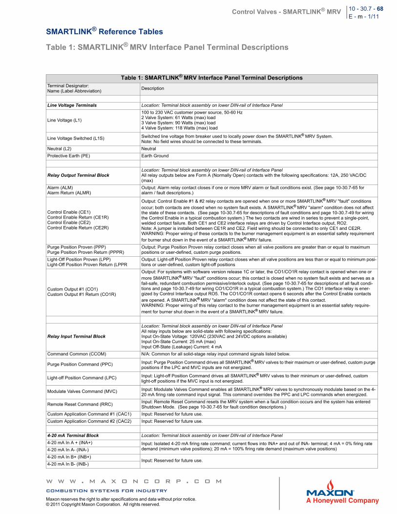
Control Valves - SMARTLINK® MRV 10 - 30.7 - 68E - m - 1/11
SMARTLINK® Reference Tables
Table 1: SMARTLINK® MRV Interface Panel Terminal Descriptions
Table 1: SMARTLINK® MRV Interface Panel Terminal DescriptionsTerminal Designator:Name (Label Abbreviation)
Description
Line Voltage Terminals Location: Terminal block assembly on lower DIN-rail of Interface Panel
Line Voltage (L1)
100 to 230 VAC customer power source, 50-60 Hz2 Valve System: 61 Watts (max) load3 Valve System: 90 Watts (max) load4 Valve System: 118 Watts (max) load
Line Voltage Switched (L1S) Switched line voltage from breaker used to locally power down the SMARTLINK® MRV System.Note: No field wires should be connected to these terminals.
Neutral (L2) Neutral
Protective Earth (PE) Earth Ground
Relay Output Terminal BlockLocation: Terminal block assembly on lower DIN-rail of Interface PanelAll relay outputs below are Form A (Normally Open) contacts with the following specifications: 12A, 250 VAC/DC (max)
Alarm (ALM)Alarm Return (ALMR)
Output: Alarm relay contact closes if one or more MRV alarm or fault conditions exist. (See page 10-30.7-65 for alarm / fault descriptions.)
Control Enable (CE1)Control Enable Return (CE1R)Control Enable (CE2)Control Enable Return (CE2R)
Output: Control Enable #1 & #2 relay contacts are opened when one or more SMARTLINK® MRV "fault" conditions
occur; both contacts are closed when no system fault exists. A SMARTLINK® MRV "alarm" condition does not affect the state of these contacts. (See page 10-30.7-65 for descriptions of fault conditions and page 10-30.7-49 for wiring the Control Enable in a typical combustion system.) The two contacts are wired in series to prevent a single-point, welded contact failure. Both CE1 and CE2 interface relays are driven by Control Interface output, RO2.Note: A jumper is installed between CE1R and CE2. Field wiring should be connected to only CE1 and CE2R.WARNING: Proper wiring of these contacts to the burner management equipment is an essential safety requirement
for burner shut down in the event of a SMARTLINK® MRV failure.
Purge Position Proven (PPP)Purge Position Proven Return (PPPR)
Output: Purge Position Proven relay contact closes when all valve positions are greater than or equal to maximum positions or user-defined, custom purge positions.
Light-Off Position Proven (LPP) Light-Off Position Proven Return (LPPR
Output: Light-off Position Proven relay contact closes when all valve positions are less than or equal to minimum posi-tions or user-defined, custom light-off positions
Custom Output #1 (CO1) Custom Output #1 Return (CO1R)
Output: For systems with software version release 1C or later, the CO1/CO1R relay contact is opened when one or
more SMARTLINK® MRV "fault" conditions occur; this contact is closed when no system fault exists and serves as a fail-safe, redundant combustion permissive/interlock output. (See page 10-30.7-65 for descriptions of all fault condi-tions and page 10-30.7-49 for wiring CO1/CO1R in a typical combustion system.) The CO1 interface relay is ener-gized by Control Interface output RO5. The CO1/CO1R contact opens 6 seconds after the Control Enable contacts
are opened. A SMARTLINK® MRV "alarm" condition does not affect the state of this contact. WARNING: Proper wiring of this relay contact to the burner management equipment is an essential safety require-
ment for burner shut down in the event of a SMARTLINK® MRV failure.
Relay Input Terminal Block
Location: Terminal block assembly on lower DIN-rail of Interface PanelAll relay inputs below are solid-state with following specifications:Input On-State Voltage: 120VAC (230VAC and 24VDC options available)Input On-State Current: 25 mA (max)Input Off-State (Leakage) Current: 4 mA
Command Common (CCOM) N/A: Common for all solid-stage relay input command signals listed below.
Purge Position Command (PPC) Input: Purge Position Command drives all SMARTLINK® MRV valves to their maximum or user-defined, custom purge positions if the LPC and MVC inputs are not energized.
Light-off Position Command (LPC) Input: Light-off Position Command drives all SMARTLINK® MRV valves to their minimum or user-defined, custom light-off positions if the MVC input is not energized.
Modulate Valves Command (MVC) Input: Modulate Valves Command enables all SMARTLINK® MRV valves to synchronously modulate based on the 4-20 mA firing rate command input signal. This command overrides the PPC and LPC commands when energized.
Remote Reset Command (RRC)Input: Remote Reset Command resets the MRV system when a fault condition occurs and the system has entered Shutdown Mode. (See page 10-30.7-65 for fault condition descriptions.)
Custom Application Command #1 (CAC1) Input: Reserved for future use.
Custom Application Command #2 (CAC2) Input: Reserved for future use.
4-20 mA Terminal Block Location: Terminal block assembly on lower DIN-rail of Interface Panel
4-20 mA In A + (INA+) Input: Isolated 4-20 mA firing rate command; current flows into INA+ and out of INA- terminal; 4 mA = 0% firing rate demand (minimum valve positions); 20 mA = 100% firing rate demand (maximum valve positions)4-20 mA In A- (INA-)
4-20 mA In B+ (INB+)Input: Reserved for future use.
4-20 mA In B- (INB-)
w w w . m a x o n c o r p . c o mcombustion systems for industryMaxon reserves the right to alter specifications and data without prior notice. © 2011 Copyright Maxon Corporation. All rights reserved.
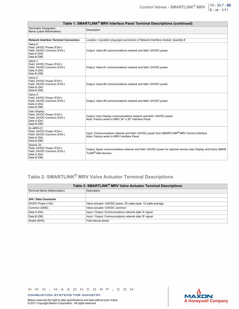
Control Valves - SMARTLINK® MRV 10 - 30.7 - 69E - m - 1/11
Table 2: SMARTLINK® MRV Valve Actuator Terminal Descriptions
Table 1: SMARTLINK® MRV Interface Panel Terminal Descriptions (continued)Terminator Designator:Name (Label Abbreviation)
Description
Network Interface Terminal Connectors Location: 4-position plug-type connectors of Network Interface module; Quantity-8
Valve-0:Field: 24VDC Power (F24+)Field: 24VDC Common (F24-)Data A (DA)Data B (DB)
Output: Valve #0 communications network and field +24VDC power
Valve-1:Field: 24VDC Power (F24+)Field: 24VDC Common (F24-)Data A (DA)Data B (DB)
Output: Valve #1 communications network and field +24VDC power
Valve-2:Field: 24VDC Power (F24+)Field: 24VDC Common (F24-)Data A (DA)Data B (DB)
Output: Valve #2 communications network and field +24VDC power
Valve-3:Field: 24VDC Power (F24+)Field: 24VDC Common (F24-)Data A (DA)Data B (DB)
Output: Valve #3 communications network and field +24VDC power
User Display:Field: 24VDC Power (F24+)Field: 24VDC Common (F24-)Data A (DA)Data B (DB)
Output: User Display communications network and field +24VDC powerNote: Factory-wired in MRV 24” x 20” Interface Panel
SL-MRV-CI:Field: 24VDC Power (F24+)Field: 24VDC Common (F24-)Data A (DA)Data B (DB)
Input: Communications network and field +24VDC power from SMARTLINK® MRV Control InterfaceNote: Factory-wired in MRV Interface Panel
Spares (2):Field: 24VDC Power (F24+)Field: 24VDC Common (F24-)Data A (DA)Data B (DB)
Output: Spare communications network and field +24VDC power for optional remote User Display and future SMAR-
TLINK® field devices.
Table 2: SMARTLINK® MRV Valve Actuator Terminal DescriptionsTerminal Name (Abbreviation) Description
24V / Data Connector
24VDC Power (+24) Valve actuator +24VDC power; 25 watts peak, 12 watts average
Common (GND) Valve actuator +24VDC common
Data A (DA) Input / Output: Communications network data ‘A’ signal
Data B (DB) Input / Output: Communications network data ‘B’ signal
Shield (SHD) Field device shield
w w w . m a x o n c o r p . c o mcombustion systems for industryMaxon reserves the right to alter specifications and data without prior notice. © 2011 Copyright Maxon Corporation. All rights reserved.
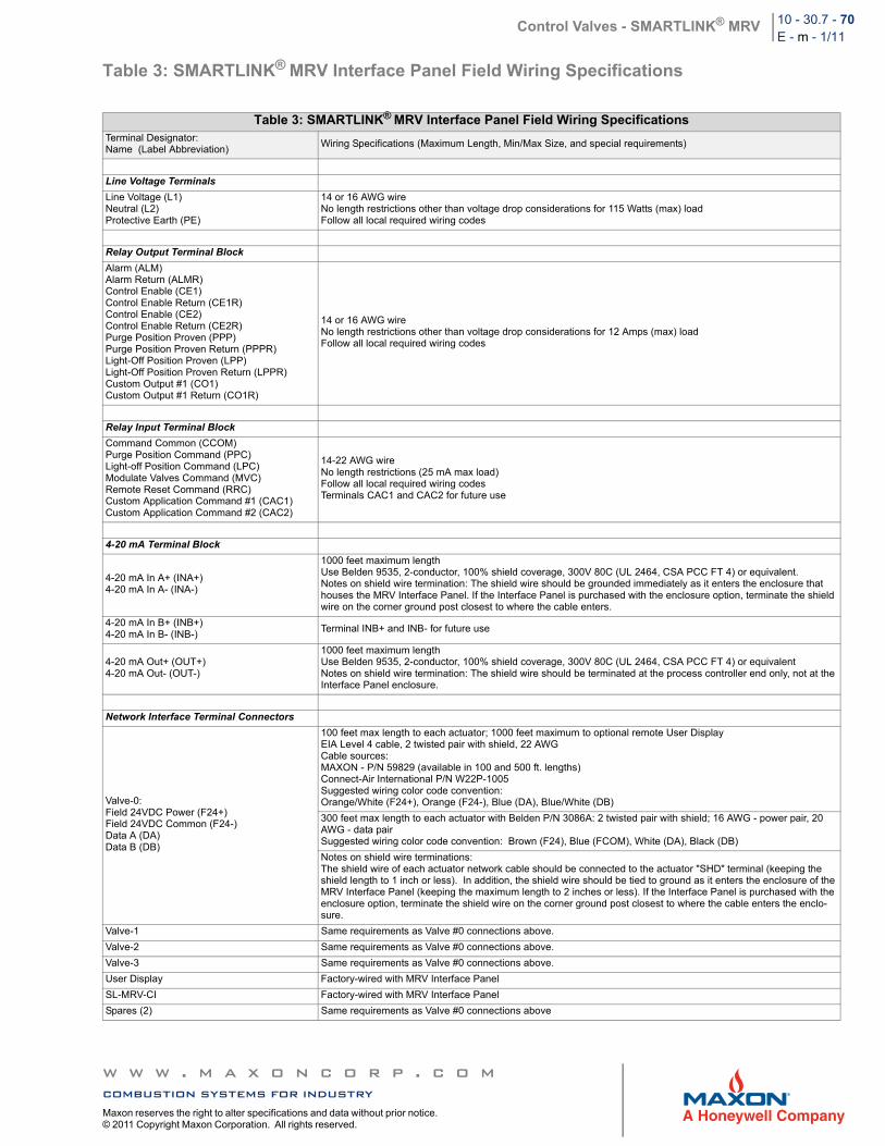
Control Valves - SMARTLINK® MRV 10 - 30.7 - 70E - m - 1/11
Table 3: SMARTLINK® MRV Interface Panel Field Wiring Specifications
Table 3: SMARTLINK® MRV Interface Panel Field Wiring SpecificationsTerminal Designator: Name (Label Abbreviation)
Wiring Specifications (Maximum Length, Min/Max Size, and special requirements)
Line Voltage Terminals
Line Voltage (L1) Neutral (L2) Protective Earth (PE)
14 or 16 AWG wireNo length restrictions other than voltage drop considerations for 115 Watts (max) loadFollow all local required wiring codes
Relay Output Terminal Block
Alarm (ALM) Alarm Return (ALMR) Control Enable (CE1) Control Enable Return (CE1R) Control Enable (CE2) Control Enable Return (CE2R) Purge Position Proven (PPP) Purge Position Proven Return (PPPR) Light-Off Position Proven (LPP) Light-Off Position Proven Return (LPPR) Custom Output #1 (CO1) Custom Output #1 Return (CO1R)
14 or 16 AWG wireNo length restrictions other than voltage drop considerations for 12 Amps (max) loadFollow all local required wiring codes
Relay Input Terminal Block
Command Common (CCOM) Purge Position Command (PPC) Light-off Position Command (LPC) Modulate Valves Command (MVC) Remote Reset Command (RRC) Custom Application Command #1 (CAC1) Custom Application Command #2 (CAC2)
14-22 AWG wireNo length restrictions (25 mA max load)Follow all local required wiring codesTerminals CAC1 and CAC2 for future use
4-20 mA Terminal Block
4-20 mA In A+ (INA+)4-20 mA In A- (INA-)
1000 feet maximum lengthUse Belden 9535, 2-conductor, 100% shield coverage, 300V 80C (UL 2464, CSA PCC FT 4) or equivalent.Notes on shield wire termination: The shield wire should be grounded immediately as it enters the enclosure that houses the MRV Interface Panel. If the Interface Panel is purchased with the enclosure option, terminate the shield wire on the corner ground post closest to where the cable enters.
4-20 mA In B+ (INB+)4-20 mA In B- (INB-)
Terminal INB+ and INB- for future use
4-20 mA Out+ (OUT+)4-20 mA Out- (OUT-)
1000 feet maximum lengthUse Belden 9535, 2-conductor, 100% shield coverage, 300V 80C (UL 2464, CSA PCC FT 4) or equivalentNotes on shield wire termination: The shield wire should be terminated at the process controller end only, not at the Interface Panel enclosure.
Network Interface Terminal Connectors
Valve-0: Field 24VDC Power (F24+) Field 24VDC Common (F24-) Data A (DA) Data B (DB)
100 feet max length to each actuator; 1000 feet maximum to optional remote User DisplayEIA Level 4 cable, 2 twisted pair with shield, 22 AWGCable sources:MAXON - P/N 59829 (available in 100 and 500 ft. lengths)Connect-Air International P/N W22P-1005Suggested wiring color code convention:Orange/White (F24+), Orange (F24-), Blue (DA), Blue/White (DB)
300 feet max length to each actuator with Belden P/N 3086A: 2 twisted pair with shield; 16 AWG - power pair, 20 AWG - data pairSuggested wiring color code convention: Brown (F24), Blue (FCOM), White (DA), Black (DB)
Notes on shield wire terminations:The shield wire of each actuator network cable should be connected to the actuator "SHD" terminal (keeping the shield length to 1 inch or less). In addition, the shield wire should be tied to ground as it enters the enclosure of the MRV Interface Panel (keeping the maximum length to 2 inches or less). If the Interface Panel is purchased with the enclosure option, terminate the shield wire on the corner ground post closest to where the cable enters the enclo-sure.
Valve-1 Same requirements as Valve #0 connections above.
Valve-2 Same requirements as Valve #0 connections above.
Valve-3 Same requirements as Valve #0 connections above.
User Display Factory-wired with MRV Interface Panel
SL-MRV-CI Factory-wired with MRV Interface Panel
Spares (2) Same requirements as Valve #0 connections above
w w w . m a x o n c o r p . c o mcombustion systems for industryMaxon reserves the right to alter specifications and data without prior notice. © 2011 Copyright Maxon Corporation. All rights reserved.
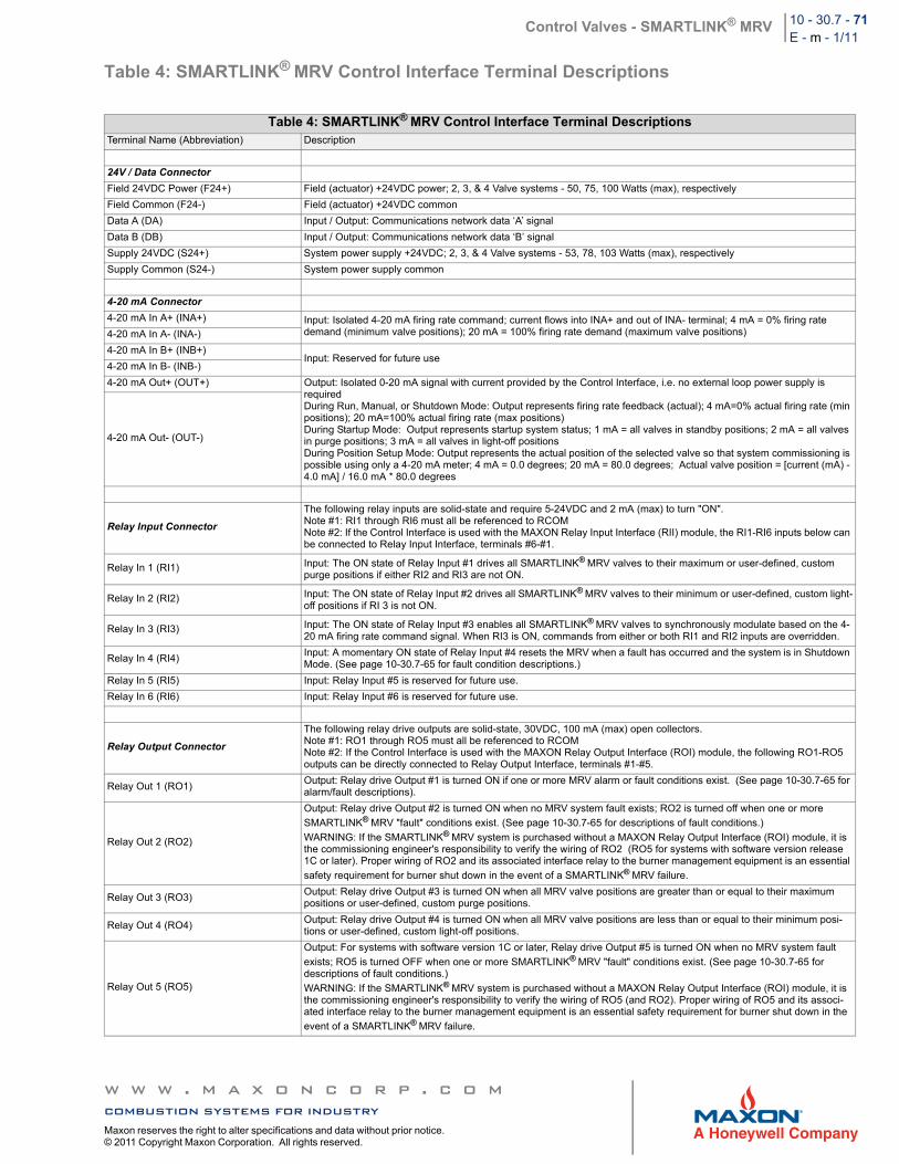
Control Valves - SMARTLINK® MRV 10 - 30.7 - 71E - m - 1/11
Table 4: SMARTLINK® MRV Control Interface Terminal Descriptions
Table 4: SMARTLINK® MRV Control Interface Terminal DescriptionsTerminal Name (Abbreviation) Description
24V / Data Connector
Field 24VDC Power (F24+) Field (actuator) +24VDC power; 2, 3, & 4 Valve systems - 50, 75, 100 Watts (max), respectively
Field Common (F24-) Field (actuator) +24VDC common
Data A (DA) Input / Output: Communications network data ‘A’ signal
Data B (DB) Input / Output: Communications network data ‘B’ signal
Supply 24VDC (S24+) System power supply +24VDC; 2, 3, & 4 Valve systems - 53, 78, 103 Watts (max), respectively
Supply Common (S24-) System power supply common
4-20 mA Connector
4-20 mA In A+ (INA+) Input: Isolated 4-20 mA firing rate command; current flows into INA+ and out of INA- terminal; 4 mA = 0% firing rate demand (minimum valve positions); 20 mA = 100% firing rate demand (maximum valve positions)4-20 mA In A- (INA-)
4-20 mA In B+ (INB+)Input: Reserved for future use
4-20 mA In B- (INB-)
4-20 mA Out+ (OUT+) Output: Isolated 0-20 mA signal with current provided by the Control Interface, i.e. no external loop power supply is requiredDuring Run, Manual, or Shutdown Mode: Output represents firing rate feedback (actual); 4 mA=0% actual firing rate (min positions); 20 mA=100% actual firing rate (max positions)During Startup Mode: Output represents startup system status; 1 mA = all valves in standby positions; 2 mA = all valves in purge positions; 3 mA = all valves in light-off positionsDuring Position Setup Mode: Output represents the actual position of the selected valve so that system commissioning is possible using only a 4-20 mA meter; 4 mA = 0.0 degrees; 20 mA = 80.0 degrees; Actual valve position = [current (mA) - 4.0 mA] / 16.0 mA * 80.0 degrees
4-20 mA Out- (OUT-)
Relay Input Connector
The following relay inputs are solid-state and require 5-24VDC and 2 mA (max) to turn "ON".Note #1: RI1 through RI6 must all be referenced to RCOMNote #2: If the Control Interface is used with the MAXON Relay Input Interface (RII) module, the RI1-RI6 inputs below can be connected to Relay Input Interface, terminals #6-#1.
Relay In 1 (RI1) Input: The ON state of Relay Input #1 drives all SMARTLINK® MRV valves to their maximum or user-defined, custom purge positions if either RI2 and RI3 are not ON.
Relay In 2 (RI2) Input: The ON state of Relay Input #2 drives all SMARTLINK® MRV valves to their minimum or user-defined, custom light-off positions if RI 3 is not ON.
Relay In 3 (RI3) Input: The ON state of Relay Input #3 enables all SMARTLINK® MRV valves to synchronously modulate based on the 4-20 mA firing rate command signal. When RI3 is ON, commands from either or both RI1 and RI2 inputs are overridden.
Relay In 4 (RI4)Input: A momentary ON state of Relay Input #4 resets the MRV when a fault has occurred and the system is in Shutdown Mode. (See page 10-30.7-65 for fault condition descriptions.)
Relay In 5 (RI5) Input: Relay Input #5 is reserved for future use.
Relay In 6 (RI6) Input: Relay Input #6 is reserved for future use.
Relay Output Connector
The following relay drive outputs are solid-state, 30VDC, 100 mA (max) open collectors.Note #1: RO1 through RO5 must all be referenced to RCOMNote #2: If the Control Interface is used with the MAXON Relay Output Interface (ROI) module, the following RO1-RO5 outputs can be directly connected to Relay Output Interface, terminals #1-#5.
Relay Out 1 (RO1)Output: Relay drive Output #1 is turned ON if one or more MRV alarm or fault conditions exist. (See page 10-30.7-65 for alarm/fault descriptions).
Relay Out 2 (RO2)
Output: Relay drive Output #2 is turned ON when no MRV system fault exists; RO2 is turned off when one or more
SMARTLINK® MRV "fault" conditions exist. (See page 10-30.7-65 for descriptions of fault conditions.)
WARNING: If the SMARTLINK® MRV system is purchased without a MAXON Relay Output Interface (ROI) module, it is the commissioning engineer's responsibility to verify the wiring of RO2 (RO5 for systems with software version release 1C or later). Proper wiring of RO2 and its associated interface relay to the burner management equipment is an essential
safety requirement for burner shut down in the event of a SMARTLINK® MRV failure.
Relay Out 3 (RO3)Output: Relay drive Output #3 is turned ON when all MRV valve positions are greater than or equal to their maximum positions or user-defined, custom purge positions.
Relay Out 4 (RO4)Output: Relay drive Output #4 is turned ON when all MRV valve positions are less than or equal to their minimum posi-tions or user-defined, custom light-off positions.
Relay Out 5 (RO5)
Output: For systems with software version 1C or later, Relay drive Output #5 is turned ON when no MRV system fault
exists; RO5 is turned OFF when one or more SMARTLINK® MRV "fault" conditions exist. (See page 10-30.7-65 for descriptions of fault conditions.)
WARNING: If the SMARTLINK® MRV system is purchased without a MAXON Relay Output Interface (ROI) module, it is the commissioning engineer's responsibility to verify the wiring of RO5 (and RO2). Proper wiring of RO5 and its associ-ated interface relay to the burner management equipment is an essential safety requirement for burner shut down in the
event of a SMARTLINK® MRV failure.
w w w . m a x o n c o r p . c o mcombustion systems for industryMaxon reserves the right to alter specifications and data without prior notice. © 2011 Copyright Maxon Corporation. All rights reserved.
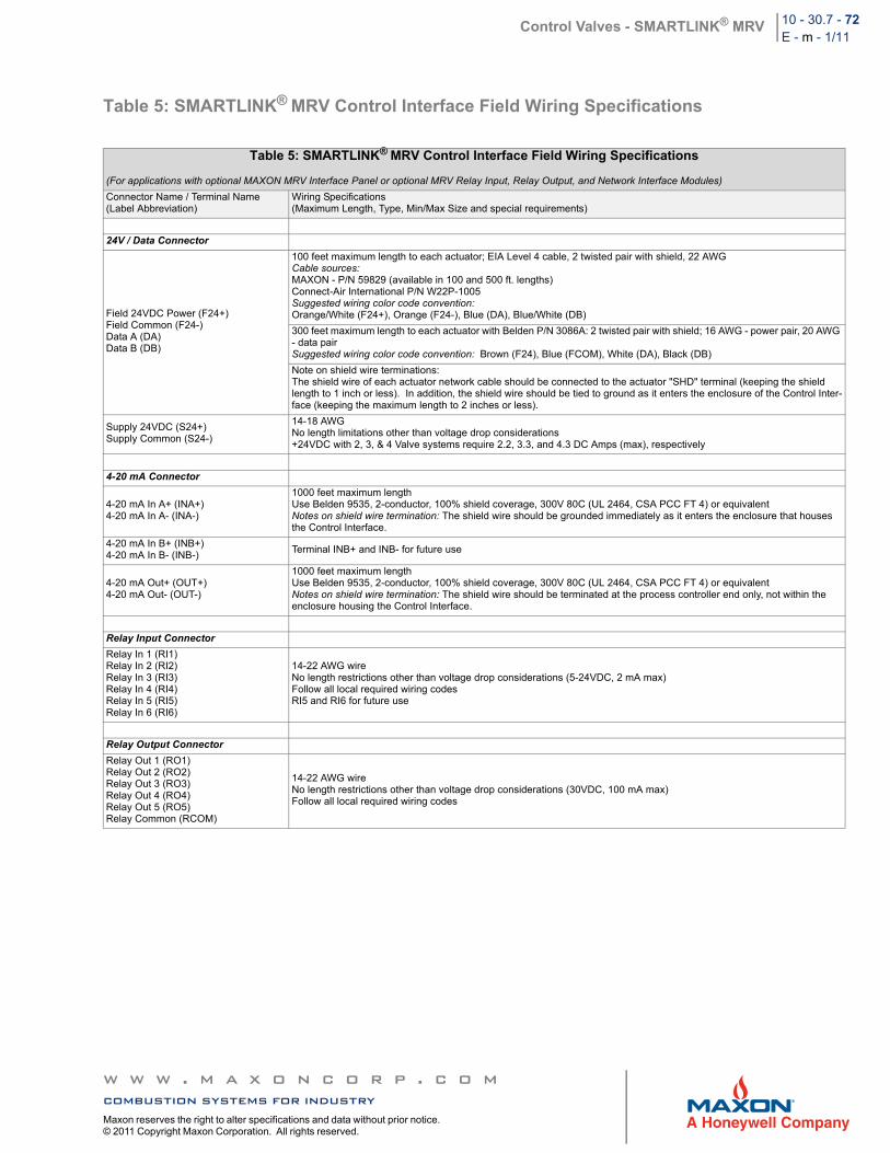
Control Valves - SMARTLINK® MRV 10 - 30.7 - 72E - m - 1/11
Table 5: SMARTLINK® MRV Control Interface Field Wiring Specifications
Table 5: SMARTLINK® MRV Control Interface Field Wiring Specifications
(For applications with optional MAXON MRV Interface Panel or optional MRV Relay Input, Relay Output, and Network Interface Modules)
Connector Name / Terminal Name (Label Abbreviation)
Wiring Specifications(Maximum Length, Type, Min/Max Size and special requirements)
24V / Data Connector
Field 24VDC Power (F24+)Field Common (F24-)Data A (DA)Data B (DB)
100 feet maximum length to each actuator; EIA Level 4 cable, 2 twisted pair with shield, 22 AWGCable sources:MAXON - P/N 59829 (available in 100 and 500 ft. lengths)Connect-Air International P/N W22P-1005Suggested wiring color code convention:Orange/White (F24+), Orange (F24-), Blue (DA), Blue/White (DB)
300 feet maximum length to each actuator with Belden P/N 3086A: 2 twisted pair with shield; 16 AWG - power pair, 20 AWG - data pairSuggested wiring color code convention: Brown (F24), Blue (FCOM), White (DA), Black (DB)
Note on shield wire terminations:The shield wire of each actuator network cable should be connected to the actuator "SHD" terminal (keeping the shield length to 1 inch or less). In addition, the shield wire should be tied to ground as it enters the enclosure of the Control Inter-face (keeping the maximum length to 2 inches or less).
Supply 24VDC (S24+)Supply Common (S24-)
14-18 AWGNo length limitations other than voltage drop considerations+24VDC with 2, 3, & 4 Valve systems require 2.2, 3.3, and 4.3 DC Amps (max), respectively
4-20 mA Connector
4-20 mA In A+ (INA+)4-20 mA In A- (INA-)
1000 feet maximum lengthUse Belden 9535, 2-conductor, 100% shield coverage, 300V 80C (UL 2464, CSA PCC FT 4) or equivalentNotes on shield wire termination: The shield wire should be grounded immediately as it enters the enclosure that houses the Control Interface.
4-20 mA In B+ (INB+)4-20 mA In B- (INB-)
Terminal INB+ and INB- for future use
4-20 mA Out+ (OUT+)4-20 mA Out- (OUT-)
1000 feet maximum lengthUse Belden 9535, 2-conductor, 100% shield coverage, 300V 80C (UL 2464, CSA PCC FT 4) or equivalentNotes on shield wire termination: The shield wire should be terminated at the process controller end only, not within the enclosure housing the Control Interface.
Relay Input Connector
Relay In 1 (RI1) Relay In 2 (RI2) Relay In 3 (RI3) Relay In 4 (RI4) Relay In 5 (RI5) Relay In 6 (RI6)
14-22 AWG wireNo length restrictions other than voltage drop considerations (5-24VDC, 2 mA max)Follow all local required wiring codesRI5 and RI6 for future use
Relay Output Connector
Relay Out 1 (RO1) Relay Out 2 (RO2) Relay Out 3 (RO3) Relay Out 4 (RO4) Relay Out 5 (RO5) Relay Common (RCOM)
14-22 AWG wireNo length restrictions other than voltage drop considerations (30VDC, 100 mA max)Follow all local required wiring codes
w w w . m a x o n c o r p . c o mcombustion systems for industryMaxon reserves the right to alter specifications and data without prior notice. © 2011 Copyright Maxon Corporation. All rights reserved.
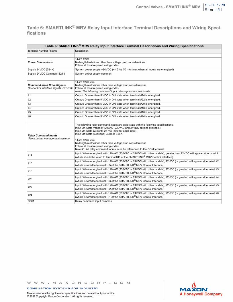
Control Valves - SMARTLINK® MRV 10 - 30.7 - 73E - m - 1/11
Table 6: SMARTLINK® MRV Relay Input Interface Terminal Descriptions and Wiring Speci-fications
Table 6: SMARTLINK® MRV Relay Input Interface Terminal Descriptions and Wiring SpecificationsTerminal Number / Name Description
Power Connections14-22 AWGNo length limitations other than voltage drop considerationsFollow all local required wiring codes
Supply 24VDC (S24+) System power supply +24VDC (+/- 5%), 50 mA (max when all inputs are energized)
Supply 24VDC Common (S24-) System power supply common
Command Input Drive Signals(To Control Interface signals, RI1-RI6)
14-22 AWG wireNo length restrictions other than voltage drop considerationsFollow all local required wiring codesNote: The following command input drive signals are solid-state
#1 Output: Greater than 5 VDC in ON state when terminal #24 is energized.
#2 Output: Greater than 5 VDC in ON state when terminal #22 is energized.
#3 Output: Greater than 5 VDC in ON state when terminal #20 is energized.
#4 Output: Greater than 5 VDC in ON state when terminal #18 is energized.
#5 Output: Greater than 5 VDC in ON state when terminal #16 is energized.
#6 Output: Greater than 5 VDC in ON state when terminal #14 is energized.
Relay Command Inputs(From burner management system)
The following relay command inputs are solid-state with the following specifications:Input On-State Voltage: 120VAC (230VAC and 24VDC options available)Input On-State Current:: 25 mA (max for each input)Input Off-State (Leakage) Current: 4 mA
14-22 AWG wireNo length restrictions other than voltage drop considerationsFollow all local required wiring codesNote #1: All relay command inputs must be referenced to the COM terminal
#14Input: When energized with 120VAC (230VAC or 24VDC with other models), greater than 22VDC will appear at terminal #1
(which should be wired to terminal RI6 of the SMARTLINK® MRV Control Interface).
#16Input: When energized with 120VAC (230VAC or 24VDC with other models), 22VDC (or greater) will appear at terminal #2
(which is wired to terminal RI5 of the SMARTLINK® MRV Control Interface).
#18Input: When energized with 120VAC (230VAC or 24VDC with other models), 22VDC (or greater) will appear at terminal #3
(which is wired to terminal RI4 of the SMARTLINK® MRV Control Interface).
#20Input: When energized with 120VAC (230VAC or 24VDC with other models), 22VDC (or greater) will appear at terminal #4
(which is wired to terminal RI3 of the SMARTLINK® MRV Control Interface).
#22Input: When energized with 120VAC (230VAC or 24VDC with other models), 22VDC (or greater) will appear at terminal #5
(which is wired to terminal RI2 of the SMARTLINK® MRV Control Interface).
#24Input: When energized with 120VAC (230VAC or 24VDC with other models), 22VDC (or greater) will appear at terminal #6
(which is wired to terminal RI1 of the SMARTLINK® MRV Control Interface).
COM Relay command input common
w w w . m a x o n c o r p . c o mcombustion systems for industryMaxon reserves the right to alter specifications and data without prior notice. © 2011 Copyright Maxon Corporation. All rights reserved.
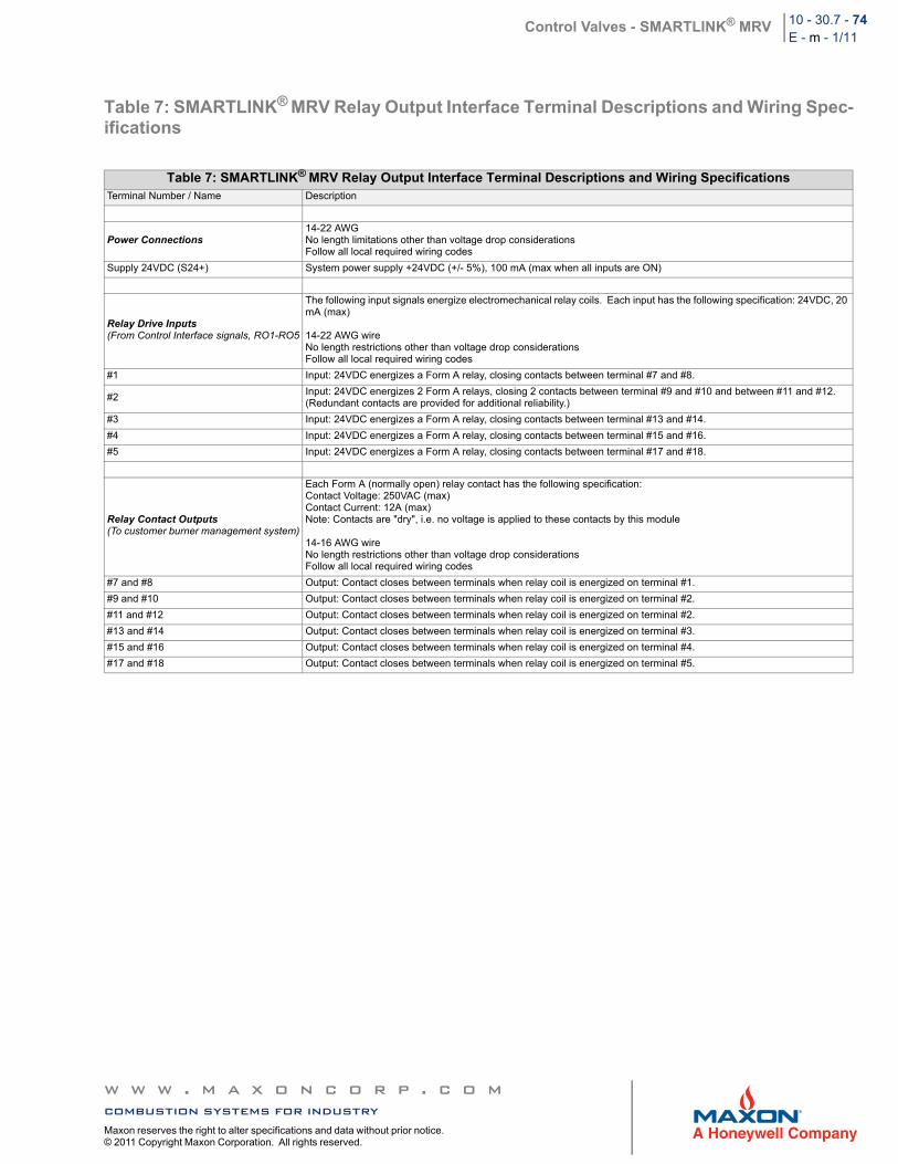
Control Valves - SMARTLINK® MRV 10 - 30.7 - 74E - m - 1/11
Table 7: SMARTLINK® MRV Relay Output Interface Terminal Descriptions and Wiring Spec-ifications
Table 7: SMARTLINK® MRV Relay Output Interface Terminal Descriptions and Wiring SpecificationsTerminal Number / Name Description
Power Connections14-22 AWGNo length limitations other than voltage drop considerationsFollow all local required wiring codes
Supply 24VDC (S24+) System power supply +24VDC (+/- 5%), 100 mA (max when all inputs are ON)
Relay Drive Inputs(From Control Interface signals, RO1-RO5
The following input signals energize electromechanical relay coils. Each input has the following specification: 24VDC, 20 mA (max)
14-22 AWG wireNo length restrictions other than voltage drop considerationsFollow all local required wiring codes
#1 Input: 24VDC energizes a Form A relay, closing contacts between terminal #7 and #8.
#2Input: 24VDC energizes 2 Form A relays, closing 2 contacts between terminal #9 and #10 and between #11 and #12. (Redundant contacts are provided for additional reliability.)
#3 Input: 24VDC energizes a Form A relay, closing contacts between terminal #13 and #14.
#4 Input: 24VDC energizes a Form A relay, closing contacts between terminal #15 and #16.
#5 Input: 24VDC energizes a Form A relay, closing contacts between terminal #17 and #18.
Relay Contact Outputs(To customer burner management system)
Each Form A (normally open) relay contact has the following specification:Contact Voltage: 250VAC (max)Contact Current: 12A (max)Note: Contacts are "dry", i.e. no voltage is applied to these contacts by this module
14-16 AWG wireNo length restrictions other than voltage drop considerationsFollow all local required wiring codes
#7 and #8 Output: Contact closes between terminals when relay coil is energized on terminal #1.
#9 and #10 Output: Contact closes between terminals when relay coil is energized on terminal #2.
#11 and #12 Output: Contact closes between terminals when relay coil is energized on terminal #2.
#13 and #14 Output: Contact closes between terminals when relay coil is energized on terminal #3.
#15 and #16 Output: Contact closes between terminals when relay coil is energized on terminal #4.
#17 and #18 Output: Contact closes between terminals when relay coil is energized on terminal #5.
w w w . m a x o n c o r p . c o mcombustion systems for industryMaxon reserves the right to alter specifications and data without prior notice. © 2011 Copyright Maxon Corporation. All rights reserved.
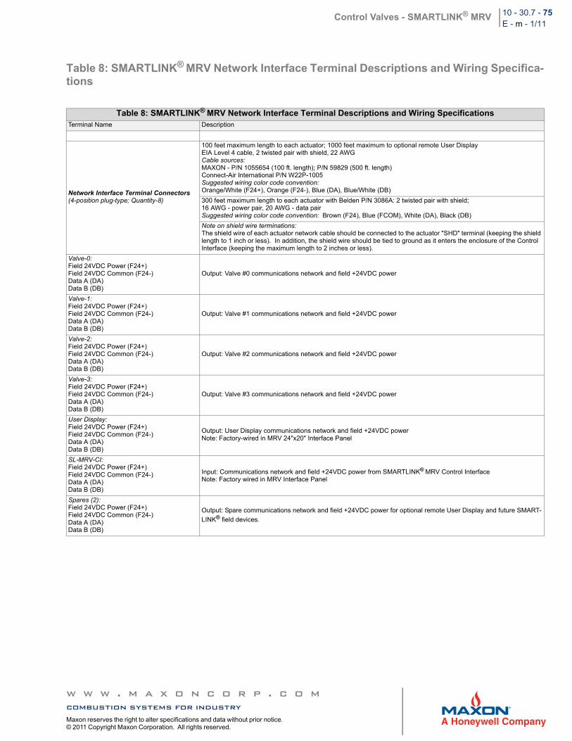
Control Valves - SMARTLINK® MRV 10 - 30.7 - 75E - m - 1/11
Table 8: SMARTLINK® MRV Network Interface Terminal Descriptions and Wiring Specifica-tions
Table 8: SMARTLINK® MRV Network Interface Terminal Descriptions and Wiring SpecificationsTerminal Name Description
Network Interface Terminal Connectors(4-position plug-type; Quantity-8)
100 feet maximum length to each actuator; 1000 feet maximum to optional remote User DisplayEIA Level 4 cable, 2 twisted pair with shield, 22 AWGCable sources:MAXON - P/N 1055654 (100 ft. length); P/N 59829 (500 ft. length)Connect-Air International P/N W22P-1005Suggested wiring color code convention:Orange/White (F24+), Orange (F24-), Blue (DA), Blue/White (DB)
300 feet maximum length to each actuator with Belden P/N 3086A: 2 twisted pair with shield;16 AWG - power pair, 20 AWG - data pairSuggested wiring color code convention: Brown (F24), Blue (FCOM), White (DA), Black (DB)
Note on shield wire terminations:The shield wire of each actuator network cable should be connected to the actuator "SHD" terminal (keeping the shield length to 1 inch or less). In addition, the shield wire should be tied to ground as it enters the enclosure of the Control Interface (keeping the maximum length to 2 inches or less).
Valve-0:Field 24VDC Power (F24+) Field 24VDC Common (F24-) Data A (DA) Data B (DB)
Output: Valve #0 communications network and field +24VDC power
Valve-1: Field 24VDC Power (F24+) Field 24VDC Common (F24-) Data A (DA) Data B (DB)
Output: Valve #1 communications network and field +24VDC power
Valve-2: Field 24VDC Power (F24+) Field 24VDC Common (F24-) Data A (DA) Data B (DB)
Output: Valve #2 communications network and field +24VDC power
Valve-3: Field 24VDC Power (F24+) Field 24VDC Common (F24-) Data A (DA) Data B (DB)
Output: Valve #3 communications network and field +24VDC power
User Display: Field 24VDC Power (F24+) Field 24VDC Common (F24-) Data A (DA) Data B (DB)
Output: User Display communications network and field +24VDC powerNote: Factory-wired in MRV 24"x20" Interface Panel
SL-MRV-CI: Field 24VDC Power (F24+) Field 24VDC Common (F24-) Data A (DA) Data B (DB)
Input: Communications network and field +24VDC power from SMARTLINK® MRV Control InterfaceNote: Factory wired in MRV Interface Panel
Spares (2): Field 24VDC Power (F24+) Field 24VDC Common (F24-) Data A (DA) Data B (DB)
Output: Spare communications network and field +24VDC power for optional remote User Display and future SMART-
LINK® field devices.
w w w . m a x o n c o r p . c o mcombustion systems for industryMaxon reserves the right to alter specifications and data without prior notice. © 2011 Copyright Maxon Corporation. All rights reserved.
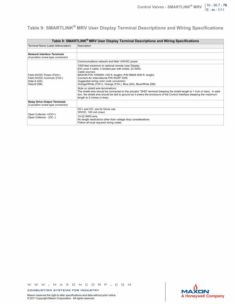
Control Valves - SMARTLINK® MRV 10 - 30.7 - 76E - m - 1/11
Table 9: SMARTLINK® MRV User Display Terminal Descriptions and Wiring Specifications
Table 9: SMARTLINK® MRV User Display Terminal Descriptions and Wiring SpecificationsTerminal Name (Label Abbreviation) Description
Network Interface Terminals(4-position screw-type connector)
Field 24VDC Power (F24+) Field 24VDC Common (F24-) Data A (DA) Data B (DB)
Communications network and field +24VDC power
1000 feet maximum to optional remote User DisplayEIA Level 4 cable, 2 twisted pair with shield, 22 AWGCable sources:MAXON P/N 1055654 (100 ft. length); P/N 59829 (500 ft. length)Connect-Air International P/N W22P-1005Suggested wiring color code convention:Orange/White (F24+), Orange (F24-), Blue (DA), Blue/White (DB)
Note on shield wire terminations:The shield wire should be connected to the actuator "SHD" terminal (keeping the shield length to 1 inch or less). In addi-tion, the shield wire should be tied to ground as it enters the enclosure of the Control Interface (keeping the maximum length to 2 inches or less).
Relay Drive Output Terminals(2-position screw-type connector)
Open Collector +(OC+) Open Collector - (OC -)
OC+ and OC- are for future use30VDC, 100 mA (max)
14-22 AWG wireNo length restrictions other than voltage drop considerationsFollow all local required wiring codes
w w w . m a x o n c o r p . c o mcombustion systems for industryMaxon reserves the right to alter specifications and data without prior notice. © 2011 Copyright Maxon Corporation. All rights reserved.
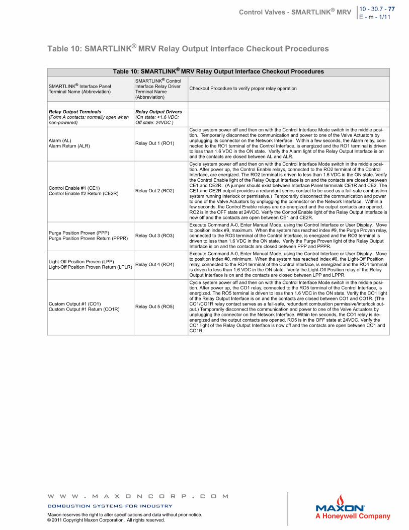
Control Valves - SMARTLINK® MRV 10 - 30.7 - 77E - m - 1/11
Table 10: SMARTLINK® MRV Relay Output Interface Checkout Procedures
Table 10: SMARTLINK® MRV Relay Output Interface Checkout Procedures
SMARTLINK® Interface Panel Terminal Name (Abbreviation)
SMARTLINK® Control Interface Relay Driver Terminal Name (Abbreviation)
Checkout Procedure to verify proper relay operation
Relay Output Terminals(Form A contacts: normally open when non-powered)
Relay Output Drivers(On state: <1.6 VDC; Off state: 24VDC )
Alarm (AL)Alarm Return (ALR)
Relay Out 1 (RO1)
Cycle system power off and then on with the Control Interface Mode switch in the middle posi-tion. Temporarily disconnect the communication and power to one of the Valve Actuators by unplugging its connector on the Network Interface. Within a few seconds, the Alarm relay, con-nected to the RO1 terminal of the Control Interface, is energized and the RO1 terminal is driven to less than 1.6 VDC in the ON state. Verify the Alarm light of the Relay Output Interface is on and the contacts are closed between AL and ALR.
Control Enable #1 (CE1)Control Enable #2 Return (CE2R)
Relay Out 2 (RO2)
Cycle system power off and then on with the Control Interface Mode switch in the middle posi-tion. After power up, the Control Enable relays, connected to the RO2 terminal of the Control Interface, are energized. The RO2 terminal is driven to less than 1.6 VDC in the ON state. Verify the Control Enable light of the Relay Output Interface is on and the contacts are closed between CE1 and CE2R. (A jumper should exist between Interface Panel terminals CE1R and CE2. The CE1 and CE2R output provides a redundant series contact to be used as a fail-safe combustion system running interlock or permissive.) Temporarily disconnect the communication and power to one of the Valve Actuators by unplugging the connector on the Network Interface. Within a few seconds, the Control Enable relays are de-energized and the output contacts are opened. RO2 is in the OFF state at 24VDC. Verify the Control Enable light of the Relay Output Interface is now off and the contacts are open between CE1 and CE2R.
Purge Position Proven (PPP)Purge Position Proven Return (PPPR)
Relay Out 3 (RO3)
Execute Command A-0, Enter Manual Mode, using the Control Interface or User Display. Move to position index #9, maximum. When the system has reached index #9, the Purge Proven relay, connected to the RO3 terminal of the Control Interface, is energized and the RO3 terminal is driven to less than 1.6 VDC in the ON state. Verify the Purge Proven light of the Relay Output Interface is on and the contacts are closed between PPP and PPPR.
Light-Off Position Proven (LPP)Light-Off Position Proven Return (LPLR)
Relay Out 4 (RO4)
Execute Command A-0, Enter Manual Mode, using the Control Interface or User Display. Move to position index #0, minimum. When the system has reached index #0, the Light-Off Position relay, connected to the RO4 terminal of the Control Interface, is energized and the RO4 terminal is driven to less than 1.6 VDC in the ON state. Verify the Light-Off Position relay of the Relay Output Interface is on and the contacts are closed between LPP and LPPR.
Custom Output #1 (CO1) Custom Output #1 Return (CO1R)
Relay Out 5 (RO5)
Cycle system power off and then on with the Control Interface Mode switch in the middle posi-tion. After power up, the CO1 relay, connected to the RO5 terminal of the Control Interface, is energized. The RO5 terminal is driven to less than 1.6 VDC in the ON state. Verify the CO1 light of the Relay Output Interface is on and the contacts are closed between CO1 and CO1R. (The CO1/CO1R relay contact serves as a fail-safe, redundant combustion permissive/interlock out-put.) Temporarily disconnect the communication and power to one of the Valve Actuators by unplugging the connector on the Network Interface. Within ten seconds, the CO1 relay is de-energized and the output contacts are opened. RO5 is in the OFF state at 24VDC. Verify the CO1 light of the Relay Output Interface is now off and the contacts are open between CO1 and CO1R.
w w w . m a x o n c o r p . c o mcombustion systems for industryMaxon reserves the right to alter specifications and data without prior notice. © 2011 Copyright Maxon Corporation. All rights reserved.
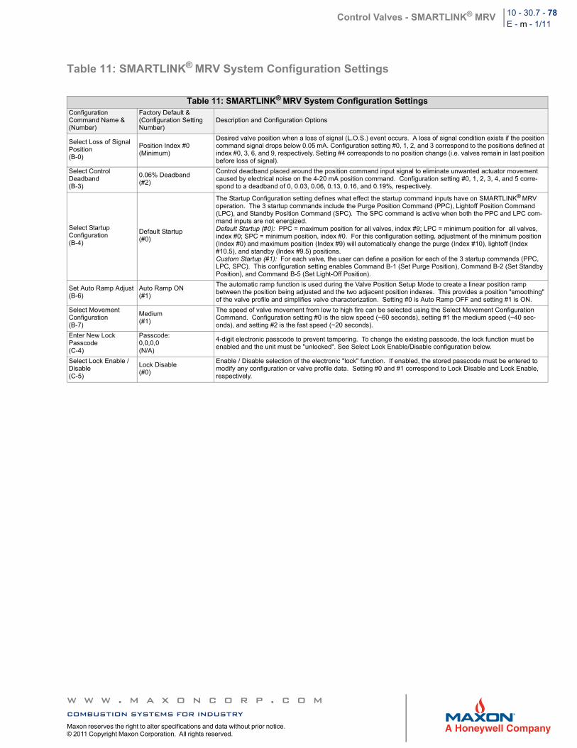
Control Valves - SMARTLINK® MRV 10 - 30.7 - 78E - m - 1/11
Table 11: SMARTLINK® MRV System Configuration Settings
Table 11: SMARTLINK® MRV System Configuration SettingsConfigurationCommand Name &(Number)
Factory Default &(Configuration Setting Number)
Description and Configuration Options
Select Loss of Signal Position (B-0)
Position Index #0(Minimum)
Desired valve position when a loss of signal (L.O.S.) event occurs. A loss of signal condition exists if the position command signal drops below 0.05 mA. Configuration setting #0, 1, 2, and 3 correspond to the positions defined at index #0, 3, 6, and 9, respectively. Setting #4 corresponds to no position change (i.e. valves remain in last position before loss of signal).
Select Control Deadband(B-3)
0.06% Deadband(#2)
Control deadband placed around the position command input signal to eliminate unwanted actuator movement caused by electrical noise on the 4-20 mA position command. Configuration setting #0, 1, 2, 3, 4, and 5 corre-spond to a deadband of 0, 0.03, 0.06, 0.13, 0.16, and 0.19%, respectively.
Select Startup Configuration (B-4)
Default Startup(#0)
The Startup Configuration setting defines what effect the startup command inputs have on SMARTLINK® MRV operation. The 3 startup commands include the Purge Position Command (PPC), Lightoff Position Command (LPC), and Standby Position Command (SPC). The SPC command is active when both the PPC and LPC com-mand inputs are not energized.Default Startup (#0): PPC = maximum position for all valves, index #9; LPC = minimum position for all valves, index #0; SPC = minimum position, index #0. For this configuration setting, adjustment of the minimum position (Index #0) and maximum position (Index #9) will automatically change the purge (Index #10), lightoff (Index #10.5), and standby (Index #9.5) positions.Custom Startup (#1): For each valve, the user can define a position for each of the 3 startup commands (PPC, LPC, SPC). This configuration setting enables Command B-1 (Set Purge Position), Command B-2 (Set Standby Position), and Command B-5 (Set Light-Off Position).
Set Auto Ramp Adjust(B-6)
Auto Ramp ON(#1)
The automatic ramp function is used during the Valve Position Setup Mode to create a linear position ramp between the position being adjusted and the two adjacent position indexes. This provides a position "smoothing" of the valve profile and simplifies valve characterization. Setting #0 is Auto Ramp OFF and setting #1 is ON.
Select Movement Configuration(B-7)
Medium(#1)
The speed of valve movement from low to high fire can be selected using the Select Movement Configuration Command. Configuration setting #0 is the slow speed (~60 seconds), setting #1 the medium speed (~40 sec-onds), and setting #2 is the fast speed (~20 seconds).
Enter New Lock Passcode(C-4)
Passcode: 0,0,0,0(N/A)
4-digit electronic passcode to prevent tampering. To change the existing passcode, the lock function must be enabled and the unit must be "unlocked". See Select Lock Enable/Disable configuration below.
Select Lock Enable / Disable(C-5)
Lock Disable(#0)
Enable / Disable selection of the electronic "lock" function. If enabled, the stored passcode must be entered to modify any configuration or valve profile data. Setting #0 and #1 correspond to Lock Disable and Lock Enable, respectively.
w w w . m a x o n c o r p . c o mcombustion systems for industryMaxon reserves the right to alter specifications and data without prior notice. © 2011 Copyright Maxon Corporation. All rights reserved.
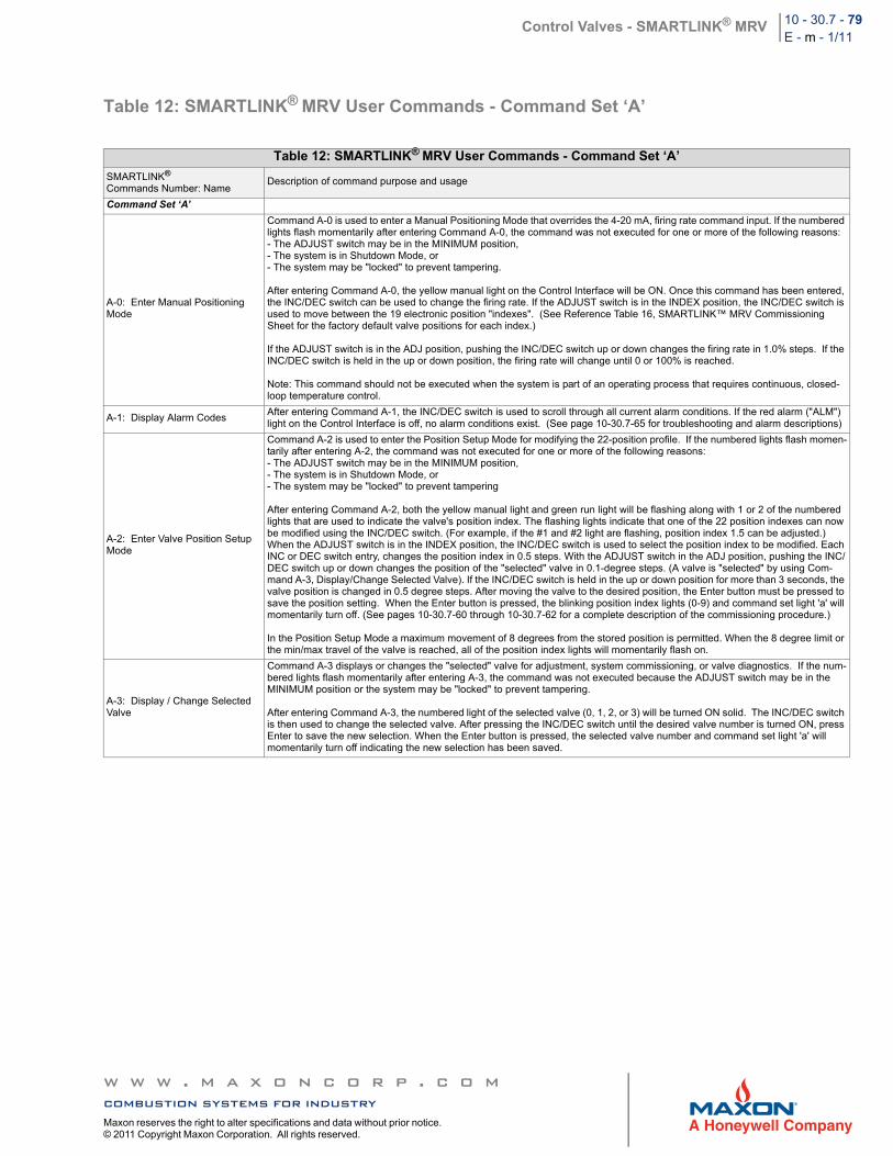
Control Valves - SMARTLINK® MRV 10 - 30.7 - 79E - m - 1/11
Table 12: SMARTLINK® MRV User Commands - Command Set ‘A’
Table 12: SMARTLINK® MRV User Commands - Command Set ‘A’
SMARTLINK®
Commands Number: NameDescription of command purpose and usage
Command Set ‘A’
A-0: Enter Manual Positioning Mode
Command A-0 is used to enter a Manual Positioning Mode that overrides the 4-20 mA, firing rate command input. If the numbered lights flash momentarily after entering Command A-0, the command was not executed for one or more of the following reasons:- The ADJUST switch may be in the MINIMUM position, - The system is in Shutdown Mode, or - The system may be "locked" to prevent tampering.
After entering Command A-0, the yellow manual light on the Control Interface will be ON. Once this command has been entered, the INC/DEC switch can be used to change the firing rate. If the ADJUST switch is in the INDEX position, the INC/DEC switch is used to move between the 19 electronic position "indexes". (See Reference Table 16, SMARTLINK™ MRV Commissioning Sheet for the factory default valve positions for each index.)
If the ADJUST switch is in the ADJ position, pushing the INC/DEC switch up or down changes the firing rate in 1.0% steps. If the INC/DEC switch is held in the up or down position, the firing rate will change until 0 or 100% is reached.
Note: This command should not be executed when the system is part of an operating process that requires continuous, closed-loop temperature control.
A-1: Display Alarm CodesAfter entering Command A-1, the INC/DEC switch is used to scroll through all current alarm conditions. If the red alarm ("ALM") light on the Control Interface is off, no alarm conditions exist. (See page 10-30.7-65 for troubleshooting and alarm descriptions)
A-2: Enter Valve Position Setup Mode
Command A-2 is used to enter the Position Setup Mode for modifying the 22-position profile. If the numbered lights flash momen-tarily after entering A-2, the command was not executed for one or more of the following reasons:- The ADJUST switch may be in the MINIMUM position,- The system is in Shutdown Mode, or- The system may be "locked" to prevent tampering
After entering Command A-2, both the yellow manual light and green run light will be flashing along with 1 or 2 of the numbered lights that are used to indicate the valve's position index. The flashing lights indicate that one of the 22 position indexes can now be modified using the INC/DEC switch. (For example, if the #1 and #2 light are flashing, position index 1.5 can be adjusted.) When the ADJUST switch is in the INDEX position, the INC/DEC switch is used to select the position index to be modified. Each INC or DEC switch entry, changes the position index in 0.5 steps. With the ADJUST switch in the ADJ position, pushing the INC/DEC switch up or down changes the position of the "selected" valve in 0.1-degree steps. (A valve is "selected" by using Com-mand A-3, Display/Change Selected Valve). If the INC/DEC switch is held in the up or down position for more than 3 seconds, the valve position is changed in 0.5 degree steps. After moving the valve to the desired position, the Enter button must be pressed to save the position setting. When the Enter button is pressed, the blinking position index lights (0-9) and command set light 'a' will momentarily turn off. (See pages 10-30.7-60 through 10-30.7-62 for a complete description of the commissioning procedure.)
In the Position Setup Mode a maximum movement of 8 degrees from the stored position is permitted. When the 8 degree limit or the min/max travel of the valve is reached, all of the position index lights will momentarily flash on.
A-3: Display / Change Selected Valve
Command A-3 displays or changes the "selected" valve for adjustment, system commissioning, or valve diagnostics. If the num-bered lights flash momentarily after entering A-3, the command was not executed because the ADJUST switch may be in the MINIMUM position or the system may be "locked" to prevent tampering.
After entering Command A-3, the numbered light of the selected valve (0, 1, 2, or 3) will be turned ON solid. The INC/DEC switch is then used to change the selected valve. After pressing the INC/DEC switch until the desired valve number is turned ON, press Enter to save the new selection. When the Enter button is pressed, the selected valve number and command set light 'a' will momentarily turn off indicating the new selection has been saved.
w w w . m a x o n c o r p . c o mcombustion systems for industryMaxon reserves the right to alter specifications and data without prior notice. © 2011 Copyright Maxon Corporation. All rights reserved.
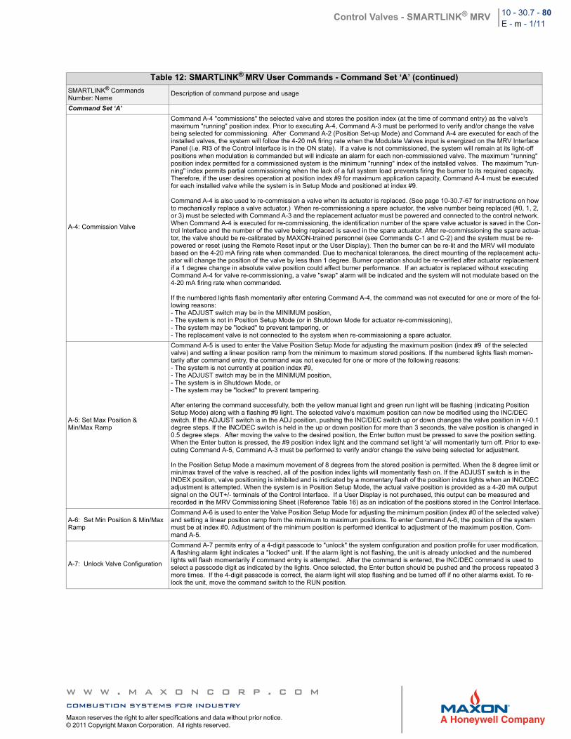
Control Valves - SMARTLINK® MRV 10 - 30.7 - 80E - m - 1/11
Table 12: SMARTLINK® MRV User Commands - Command Set ‘A’ (continued)
SMARTLINK® Commands Number: Name
Description of command purpose and usage
Command Set ‘A’
A-4: Commission Valve
Command A-4 "commissions" the selected valve and stores the position index (at the time of command entry) as the valve's maximum "running" position index. Prior to executing A-4, Command A-3 must be performed to verify and/or change the valve being selected for commissioning. After Command A-2 (Position Set-up Mode) and Command A-4 are executed for each of the installed valves, the system will follow the 4-20 mA firing rate when the Modulate Valves input is energized on the MRV Interface Panel (i.e. RI3 of the Control Interface is in the ON state). If a valve is not commissioned, the system will remain at its light-off positions when modulation is commanded but will indicate an alarm for each non-commissioned valve. The maximum "running" position index permitted for a commissioned system is the minimum "running" index of the installed valves. The maximum "run-ning" index permits partial commissioning when the lack of a full system load prevents firing the burner to its required capacity. Therefore, if the user desires operation at position index #9 for maximum application capacity, Command A-4 must be executed for each installed valve while the system is in Setup Mode and positioned at index #9.
Command A-4 is also used to re-commission a valve when its actuator is replaced. (See page 10-30.7-67 for instructions on how to mechanically replace a valve actuator.) When re-commissioning a spare actuator, the valve number being replaced (#0, 1, 2, or 3) must be selected with Command A-3 and the replacement actuator must be powered and connected to the control network. When Command A-4 is executed for re-commissioning, the identification number of the spare valve actuator is saved in the Con-trol Interface and the number of the valve being replaced is saved in the spare actuator. After re-commissioning the spare actua-tor, the valve should be re-calibrated by MAXON-trained personnel (see Commands C-1 and C-2) and the system must be re-powered or reset (using the Remote Reset input or the User Display). Then the burner can be re-lit and the MRV will modulate based on the 4-20 mA firing rate when commanded. Due to mechanical tolerances, the direct mounting of the replacement actu-ator will change the position of the valve by less than 1 degree. Burner operation should be re-verified after actuator replacement if a 1 degree change in absolute valve position could affect burner performance. If an actuator is replaced without executing Command A-4 for valve re-commissioning, a valve "swap" alarm will be indicated and the system will not modulate based on the 4-20 mA firing rate when commanded.
If the numbered lights flash momentarily after entering Command A-4, the command was not executed for one or more of the fol-lowing reasons:- The ADJUST switch may be in the MINIMUM position,- The system is not in Position Setup Mode (or in Shutdown Mode for actuator re-commissioning), - The system may be "locked" to prevent tampering, or- The replacement valve is not connected to the system when re-commissioning a spare actuator.
A-5: Set Max Position &Min/Max Ramp
Command A-5 is used to enter the Valve Position Setup Mode for adjusting the maximum position (index #9 of the selected valve) and setting a linear position ramp from the minimum to maximum stored positions. If the numbered lights flash momen-tarily after command entry, the command was not executed for one or more of the following reasons:- The system is not currently at position index #9,- The ADJUST switch may be in the MINIMUM position,- The system is in Shutdown Mode, or - The system may be "locked" to prevent tampering.
After entering the command successfully, both the yellow manual light and green run light will be flashing (indicating Position Setup Mode) along with a flashing #9 light. The selected valve's maximum position can now be modified using the INC/DEC switch. If the ADJUST switch is in the ADJ position, pushing the INC/DEC switch up or down changes the valve position in +/-0.1 degree steps. If the INC/DEC switch is held in the up or down position for more than 3 seconds, the valve position is changed in 0.5 degree steps. After moving the valve to the desired position, the Enter button must be pressed to save the position setting. When the Enter button is pressed, the #9 position index light and the command set light 'a' will momentarily turn off. Prior to exe-cuting Command A-5, Command A-3 must be performed to verify and/or change the valve being selected for adjustment.
In the Position Setup Mode a maximum movement of 8 degrees from the stored position is permitted. When the 8 degree limit or min/max travel of the valve is reached, all of the position index lights will momentarily flash on. If the ADJUST switch is in the INDEX position, valve positioning is inhibited and is indicated by a momentary flash of the position index lights when an INC/DEC adjustment is attempted. When the system is in Position Setup Mode, the actual valve position is provided as a 4-20 mA output signal on the OUT+/- terminals of the Control Interface. If a User Display is not purchased, this output can be measured and recorded in the MRV Commissioning Sheet (Reference Table 16) as an indication of the positions stored in the Control Interface.
A-6: Set Min Position & Min/Max Ramp
Command A-6 is used to enter the Valve Position Setup Mode for adjusting the minimum position (index #0 of the selected valve) and setting a linear position ramp from the minimum to maximum positions. To enter Command A-6, the position of the system must be at index #0. Adjustment of the minimum position is performed identical to adjustment of the maximum position, Com-mand A-5.
A-7: Unlock Valve Configuration
Command A-7 permits entry of a 4-digit passcode to "unlock" the system configuration and position profile for user modification. A flashing alarm light indicates a "locked" unit. If the alarm light is not flashing, the unit is already unlocked and the numbered lights will flash momentarily if command entry is attempted. After the command is entered, the INC/DEC command is used to select a passcode digit as indicated by the lights. Once selected, the Enter button should be pushed and the process repeated 3 more times. If the 4-digit passcode is correct, the alarm light will stop flashing and be turned off if no other alarms exist. To re-lock the unit, move the command switch to the RUN position.
w w w . m a x o n c o r p . c o mcombustion systems for industryMaxon reserves the right to alter specifications and data without prior notice. © 2011 Copyright Maxon Corporation. All rights reserved.
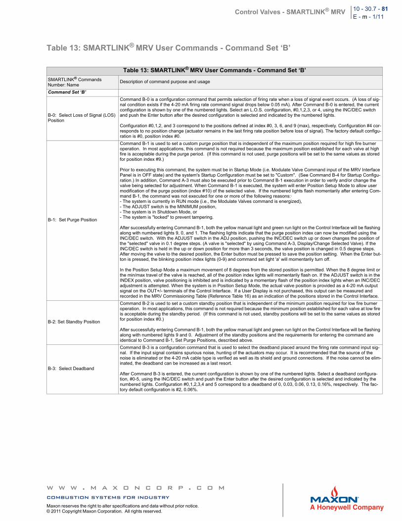
Control Valves - SMARTLINK® MRV 10 - 30.7 - 81E - m - 1/11
Table 13: SMARTLINK® MRV User Commands - Command Set ‘B’
Table 13: SMARTLINK® MRV User Commands - Command Set ‘B’
SMARTLINK® CommandsNumber: Name
Description of command purpose and usage
Command Set ‘B’
B-0: Select Loss of Signal (LOS) Position
Command B-0 is a configuration command that permits selection of firing rate when a loss of signal event occurs. (A loss of sig-nal condition exists if the 4-20 mA firing rate command signal drops below 0.05 mA). After Command B-0 is entered, the current configuration is shown by one of the numbered lights. Select an L.O.S. configuration, #0,1,2,3, or 4, using the INC/DEC switch and push the Enter button after the desired configuration is selected and indicated by the numbered lights.
Configuration #0,1,2, and 3 correspond to the positions defined at index #0, 3, 6, and 9 (max), respectively. Configuration #4 cor-responds to no position change (actuator remains in the last firing rate position before loss of signal). The factory default configu-ration is #0, position index #0.
B-1: Set Purge Position
Command B-1 is used to set a custom purge position that is independent of the maximum position required for high fire burner operation. In most applications, this command is not required because the maximum position established for each valve at high fire is acceptable during the purge period. (If this command is not used, purge positions will be set to the same values as stored for position index #9.)
Prior to executing this command, the system must be in Startup Mode (i.e. Modulate Valve Command input of the MRV Interface Panel is in OFF state) and the system's Startup Configuration must be set to "Custom". (See Command B-4 for Startup Configu-ration.) In addition, Command A-3 must also be executed prior to Command B-1 execution in order to verify and/or change the valve being selected for adjustment. When Command B-1 is executed, the system will enter Position Setup Mode to allow user modification of the purge position (index #10) of the selected valve. If the numbered lights flash momentarily after entering Com-mand B-1, the command was not executed for one or more of the following reasons:·- The system is currently in RUN mode (i.e., the Modulate Valves command is energized),- The ADJUST switch is the MINIMUM position,- The system is in Shutdown Mode, or- The system is "locked" to prevent tampering.
After successfully entering Command B-1, both the yellow manual light and green run light on the Control Interface will be flashing along with numbered lights 9, 0, and 1. The flashing lights indicate that the purge position index can now be modified using the INC/DEC switch. With the ADJUST switch in the ADJ position, pushing the INC/DEC switch up or down changes the position of the "selected" valve in 0.1 degree steps. (A valve is "selected" by using Command A-3, Display/Change Selected Valve). If the INC/DEC switch is held in the up or down position for more than 3 seconds, the valve position is changed in 0.5 degree steps. After moving the valve to the desired position, the Enter button must be pressed to save the position setting. When the Enter but-ton is pressed, the blinking position index lights (0-9) and command set light 'a' will momentarily turn off.
In the Position Setup Mode a maximum movement of 8 degrees from the stored position is permitted. When the 8 degree limit or the min/max travel of the valve is reached, all of the position index lights will momentarily flash on. If the ADJUST switch is in the INDEX position, valve positioning is inhibited and is indicated by a momentary flash of the position index lights when an INC/DEC adjustment is attempted. When the system is in Position Setup Mode, the actual valve position is provided as a 4-20 mA output signal on the OUT+/- terminals of the Control Interface. If a User Display is not purchased, this output can be measured and recorded in the MRV Commissioning Table (Reference Table 16) as an indication of the positions stored in the Control Interface.
B-2: Set Standby Position
Command B-2 is used to set a custom standby position that is independent of the minimum position required for low fire burner operation. In most applications, this command is not required because the minimum position established for each valve at low fire is acceptable during the standby period. (If this command is not used, standby positions will be set to the same values as stored for position index #0.)
After successfully entering Command B-1, both the yellow manual light and green run light on the Control Interface will be flashing along with numbered lights 9 and 0. Adjustment of the standby positions and the requirements for entering the command are identical to Command B-1, Set Purge Positions, described above.
B-3: Select Deadband
Command B-3 is a configuration command that is used to select the deadband placed around the firing rate command input sig-nal. If the input signal contains spurious noise, hunting of the actuators may occur. It is recommended that the source of the noise is eliminated or the 4-20 mA cable type is verified as well as its shield and ground connections. If the noise cannot be elim-inated, the deadband can be increased as a last resort.
After Command B-3 is entered, the current configuration is shown by one of the numbered lights. Select a deadband configura-tion, #0-5, using the INC/DEC switch and push the Enter button after the desired configuration is selected and indicated by the numbered lights. Configuration #0,1,2,3,4 and 5 correspond to a deadband of 0, 0.03, 0.06, 0.13, 0.16%, respectively. The fac-tory default configuration is #2, 0.06%.
w w w . m a x o n c o r p . c o mcombustion systems for industryMaxon reserves the right to alter specifications and data without prior notice. © 2011 Copyright Maxon Corporation. All rights reserved.
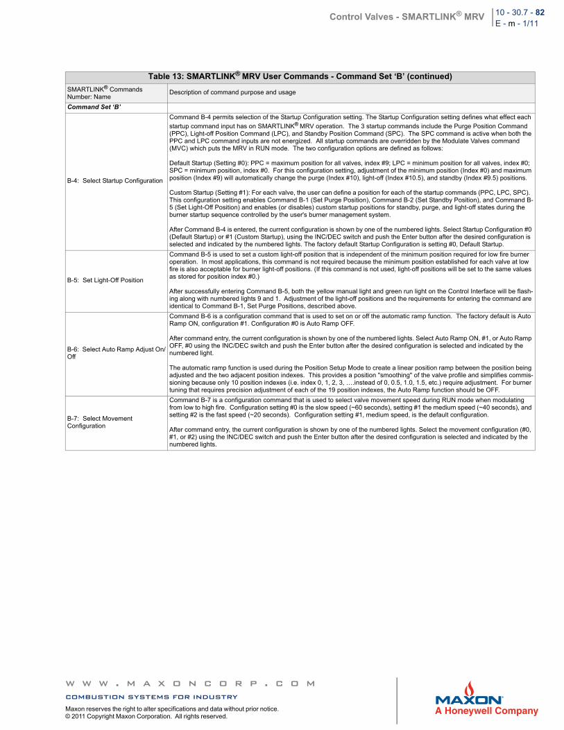
Control Valves - SMARTLINK® MRV 10 - 30.7 - 82E - m - 1/11
Table 13: SMARTLINK® MRV User Commands - Command Set ‘B’ (continued)
SMARTLINK® CommandsNumber: Name
Description of command purpose and usage
Command Set ‘B’
B-4: Select Startup Configuration
Command B-4 permits selection of the Startup Configuration setting. The Startup Configuration setting defines what effect each
startup command input has on SMARTLINK® MRV operation. The 3 startup commands include the Purge Position Command (PPC), Light-off Position Command (LPC), and Standby Position Command (SPC). The SPC command is active when both the PPC and LPC command inputs are not energized. All startup commands are overridden by the Modulate Valves command (MVC) which puts the MRV in RUN mode. The two configuration options are defined as follows:
Default Startup (Setting #0): PPC = maximum position for all valves, index #9; LPC = minimum position for all valves, index #0; SPC = minimum position, index #0. For this configuration setting, adjustment of the minimum position (Index #0) and maximum position (Index #9) will automatically change the purge (Index #10), light-off (Index #10.5), and standby (Index #9.5) positions.
Custom Startup (Setting #1): For each valve, the user can define a position for each of the startup commands (PPC, LPC, SPC). This configuration setting enables Command B-1 (Set Purge Position), Command B-2 (Set Standby Position), and Command B-5 (Set Light-Off Position) and enables (or disables) custom startup positions for standby, purge, and light-off states during the burner startup sequence controlled by the user's burner management system.
After Command B-4 is entered, the current configuration is shown by one of the numbered lights. Select Startup Configuration #0 (Default Startup) or #1 (Custom Startup), using the INC/DEC switch and push the Enter button after the desired configuration is selected and indicated by the numbered lights. The factory default Startup Configuration is setting #0, Default Startup.
B-5: Set Light-Off Position
Command B-5 is used to set a custom light-off position that is independent of the minimum position required for low fire burner operation. In most applications, this command is not required because the minimum position established for each valve at low fire is also acceptable for burner light-off positions. (If this command is not used, light-off positions will be set to the same values as stored for position index #0.)
After successfully entering Command B-5, both the yellow manual light and green run light on the Control Interface will be flash-ing along with numbered lights 9 and 1. Adjustment of the light-off positions and the requirements for entering the command are identical to Command B-1, Set Purge Positions, described above.
B-6: Select Auto Ramp Adjust On/Off
Command B-6 is a configuration command that is used to set on or off the automatic ramp function. The factory default is Auto Ramp ON, configuration #1. Configuration #0 is Auto Ramp OFF.
After command entry, the current configuration is shown by one of the numbered lights. Select Auto Ramp ON, #1, or Auto Ramp OFF, #0 using the INC/DEC switch and push the Enter button after the desired configuration is selected and indicated by the numbered light.
The automatic ramp function is used during the Position Setup Mode to create a linear position ramp between the position being adjusted and the two adjacent position indexes. This provides a position "smoothing" of the valve profile and simplifies commis-sioning because only 10 position indexes (i.e. index 0, 1, 2, 3, ….instead of 0, 0.5, 1.0, 1.5, etc.) require adjustment. For burner tuning that requires precision adjustment of each of the 19 position indexes, the Auto Ramp function should be OFF.
B-7: Select Movement Configuration
Command B-7 is a configuration command that is used to select valve movement speed during RUN mode when modulating from low to high fire. Configuration setting #0 is the slow speed (~60 seconds), setting #1 the medium speed (~40 seconds), and setting #2 is the fast speed (~20 seconds). Configuration setting #1, medium speed, is the default configuration.
After command entry, the current configuration is shown by one of the numbered lights. Select the movement configuration (#0, #1, or #2) using the INC/DEC switch and push the Enter button after the desired configuration is selected and indicated by the numbered lights.
w w w . m a x o n c o r p . c o mcombustion systems for industryMaxon reserves the right to alter specifications and data without prior notice. © 2011 Copyright Maxon Corporation. All rights reserved.
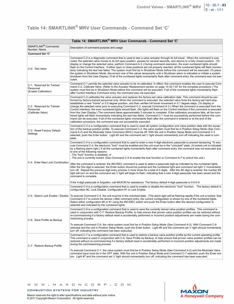
Control Valves - SMARTLINK® MRV 10 - 30.7 - 83E - m - 1/11
Table 14: SMARTLINK® MRV User Commands - Command Set ‘C’
Table 14: SMARTLINK® MRV User Commands - Command Set ‘C’
SMARTLINK® CommandsNumber: Name
Description of command purpose and usage
Command Set ‘C’
C-0: Test Valve
Command C-0 is a diagnostic command that is used to test a valve actuator through its full travel. When the command is exe-cuted, the selected valve moves to its full open position, pauses for several seconds, and returns to a fully closed position. (To display or change the selected valve, perform Command A-3.) During command execution, the even numbered lights should flash on the Control Interface. If either open or close positions are not properly reached, all the numbered lights will flash momen-tarily indicating the test has failed. The system must first be in Shutdown Mode before this command will be executed. (To place the system in Shutdown Mode, disconnect one of the valves temporarily until a Shutdown alarm is indicated or initiate a system shutdown from the User Display.) If all of the numbered lights momentarily flash after command entry, the command was not exe-cuted.
C-1: Reserved for Trained Personnel(Enable Calibration)
Command C-1 permits the selected valve actuator to be re-calibrated. In effect, this command enables the user to execute Com-mand C-2, Calibrate Valve. (Refer to the Actuator Replacement section on page 10-30.7-67 for the complete procedure.) The system must first be in Shutdown Mode before this command will be executed. If all of the numbered lights momentarily flash after Control Interface Command entry, the command was not executed.
C-2: Reserved for Trained Personnel(Calibrate Valve)
Command C-2 calibrates the valve actuator and replaces the factory-set valve calibration data. This command should be per-formed by factory-trained personnel only. When the command is executed, the selected valve finds the factory-set hard-stop, establishes a new "home" or 0.0 degree position, and then verifies full travel movement in 0.1 degree steps. (To display or change the selected valve prior to executing Command C-2, execute Command A-3.) When the command is executed from the Control Interface, the even numbered lights should flash. (No lights will flash on the Control Interface if this command is executed from the User Display.) The command takes approximately 3 minutes to complete. If the calibration procedure fails, all the num-bered lights will flash momentarily indicating the test has failed. Command C-1 must be successfully performed before this com-mand can be executed. If all of the numbered lights momentarily flash after the command is entered or at the end of the calibration procedure, the command was not successfully executed.
C-3: Reset Factory Default Settings
Command C-3 is a configuration command that is used to reset all system configuration and valve position data with the excep-tion of the backup position profile. To execute Command C-3, the valve system must first be in Position Setup Mode (See Com-mand A-2) and the Modulate Valve Command (MVC) must be off. With the unit in Position Setup Mode and Command C-3 selected, push the Enter button. Light #3 and the command set 'c' light should momentarily turn off indicating the reset is com-plete.
C-4: Enter New Lock Combination
Command C-4 is a configuration command that is used to enter a new 4-digit electronic passcode to prevent tampering. To exe-cute Command C-4, the electronic "lock" must be enabled and the unit must be in the "unlocked" state. (A locked unit is indicated by a flashing alarm light.) If all the numbered lights momentarily flash after command entry, the command was not executed due to one of the following reasons:- The "lock" function is disabled, or- The unit is currently locked. (See Command C-5 to enable the lock function or Command A-7 to unlock the unit.)
After the command is entered, the INC/DEC command is used to select a passcode digit as indicated by the numbered lights. After the first digit is selected, the Enter button should be pushed and the numbered light and command set light 'c' momentarily turn off. Repeat the previous digit entry process 3 more times for a total of 4 digits. After the 4th digit is entered, the number #4 light will turn on and the command set 'c' light will begin to flash, indicating that a new 4-digit passcode has been saved and the command is complete.
If the 4-digit passcode is forgotten, call MAXON for assistance. The factory default 4-digit passcode is 0-0-0-0.
C-5: Select Lock Enable / Disable
Command C-5 is a configuration command that is used to enable or disable the electronic "lock" function. The factory default is configuration #0, Lock Disable. Configuration #1 is Lock Enable.
To execute Command C-5, the unit must be in the unlocked state. (The alarm light will be flashing rapidly if the unit is locked. See Command A-7 to unlock the device.) After command entry, the current configuration is shown by one of the numbered lights. Select either configuration #0 or #1 using the INC/DEC switch and push the Enter button after the desired configuration is selected and indicated by the numbered lights.
C-6: Save Profile as Backup
Command C-6 is a configuration command that is used to save the currently stored valve position profiles. This command is used in conjunction with C-7, Restore Backup Profile, to help ensure that proven valve position profiles can be restored without re-commissioning if a factory default reset is accidentally performed or incorrect position adjustments are made during the com-missioning process.
To execute Command C-6, the valve system must first be in Position Setup Mode (See Command A-2). With Command C-6 selected and the unit in Position Setup Mode, push the Enter button. Light #6 and the command set 'c' light should momentarily turn off, indicating the command has been executed.
C-7: Restore Backup Profile
Command C-7 is a configuration command that is used to restore a backup valve position profile as the current operating profile. This command is used in conjunction with C-6, Save Profile as Backup, to help ensure that proven valve position profiles can be restored without re-commissioning if a factory default reset is accidentally performed or incorrect position adjustments are made during the commissioning process.
To execute Command C-7, the valve system must first be in Position Setup Mode (See Command A-2) and the Modulate Valve command input must be in the OFF state. With the unit in Position Setup Mode and Command C-7 selected, push the Enter but-ton. Light #7 and the command set 'c' light should momentarily turn off, indicating the command has been executed.
w w w . m a x o n c o r p . c o mcombustion systems for industryMaxon reserves the right to alter specifications and data without prior notice. © 2011 Copyright Maxon Corporation. All rights reserved.
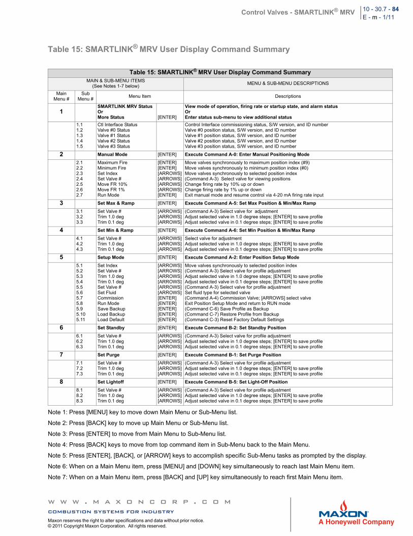
Control Valves - SMARTLINK® MRV 10 - 30.7 - 84E - m - 1/11
Table 15: SMARTLINK® MRV User Display Command Summary
Note 1: Press [MENU] key to move down Main Menu or Sub-Menu list.
Note 2: Press [BACK] key to move up Main Menu or Sub-Menu list.
Note 3: Press [ENTER] to move from Main Menu to Sub-Menu list.
Note 4: Press [BACK] keys to move from top command item in Sub-Menu back to the Main Menu.
Note 5: Press [ENTER], [BACK], or [ARROW] keys to accomplish specific Sub-Menu tasks as prompted by the display.
Note 6: When on a Main Menu item, press [MENU] and [DOWN] key simultaneously to reach last Main Menu item.
Note 7: When on a Main Menu item, press [BACK] and [UP] key simultaneously to reach first Main Menu item.
Table 15: SMARTLINK® MRV User Display Command SummaryMAIN & SUB-MENU ITEMS
(See Notes 1-7 below)MENU & SUB-MENU DESCRIPTIONS
Main Menu #
SubMenu #
Menu Item Descriptions
1SMARTLINK MRV StatusOrMore Status [ENTER]
View mode of operation, firing rate or startup state, and alarm statusOrEnter status sub-menu to view additional status
1.11.21.31.41.5
Ctl Interface Status Valve #0 Status Valve #1 Status Valve #2 Status Valve #3 Status
Control Interface commissioning status, S/W version, and ID number Valve #0 position status, S/W version, and ID number Valve #1 position status, S/W version, and ID number Valve #2 position status, S/W version, and ID number Valve #3 position status, S/W version, and ID number
2 Manual Mode [ENTER] Execute Command A-0: Enter Manual Positioning Mode
2.12.22.32.42.52.62.7
Maximum FireMinimum FireSet IndexSet Valve #Move FR 10%Move FR 1%Run Mode
[ENTER][ENTER][ARROWS][ARROWS][ARROWS][ARROWS][ENTER]
Move valves synchronously to maximum position index (#9) Move valves synchronously to minimum position index (#0) Move valves synchronously to selected position index (Command A-3) Select valve for viewing positions Change firing rate by 10% up or down Change firing rate by 1% up or down Exit manual mode and resume control via 4-20 mA firing rate input
3 Set Max & Ramp [ENTER] Execute Command A-5: Set Max Position & Min/Max Ramp
3.13.23.3
Set Valve #Trim 1.0 degTrim 0.1 deg
[ARROWS][ARROWS][ARROWS]
(Command A-3) Select valve for adjustment Adjust selected valve in 1.0 degree steps; [ENTER] to save profile Adjust selected valve in 0.1 degree steps; [ENTER] to save profile
4 Set Min & Ramp [ENTER] Execute Command A-6: Set Min Position & Min/Max Ramp
4.14.24.3
Set Valve #Trim 1.0 degTrim 0.1 deg
[ARROWS][ARROWS][ARROWS]
Select valve for adjustment Adjust selected valve in 1.0 degree steps; [ENTER] to save profile Adjust selected valve in 0.1 degree steps; [ENTER] to save profile
5 Setup Mode [ENTER] Execute Command A-2: Enter Position Setup Mode
5.15.25.35.45.55.65.75.85.95.105.11
Set IndexSet Valve #Trim 1.0 degTrim 0.1 degSet Valve #Set FluidCommissionRun ModeSave BackupLoad BackupLoad Default
[ARROWS][ARROWS][ARROWS][ARROWS][ARROWS][ARROWS][ENTER][ENTER][ENTER][ENTER][ENTER]
Move valves synchronously to selected position index (Command A-3) Select valve for profile adjustment Adjust selected valve in 1.0 degree steps; [ENTER] to save profile Adjust selected valve in 0.1 degree steps; [ENTER] to save profile (Command A-3) Select valve for profile adjustment Set fluid type for selected valve (Command A-4) Commission Valve; [ARROWS] select valve Exit Position Setup Mode and return to RUN mode (Command C-6) Save Profile as Backup (Command C-7) Restore Profile from Backup (Command C-3) Reset Factory Default Settings
6 Set Standby [ENTER] Execute Command B-2: Set Standby Position
6.16.26.3
Set Valve #Trim 1.0 degTrim 0.1 deg
[ARROWS][ARROWS][ARROWS]
(Command A-3) Select valve for profile adjustment Adjust selected valve in 1.0 degree steps; [ENTER] to save profile Adjust selected valve in 0.1 degree steps; [ENTER] to save profile
7 Set Purge [ENTER] Execute Command B-1: Set Purge Position
7.17.27.3
Set Valve #Trim 1.0 degTrim 0.1 deg
[ARROWS][ARROWS][ARROWS]
(Command A-3) Select valve for profile adjustment Adjust selected valve in 1.0 degree steps; [ENTER] to save profile Adjust selected valve in 0.1 degree steps; [ENTER] to save profile
8 Set Lightoff [ENTER] Execute Command B-5: Set Light-Off Position
8.18.28.3
Set Valve #Trim 1.0 degTrim 0.1 deg
[ARROWS][ARROWS][ARROWS]
(Command A-3) Select valve for profile adjustment Adjust selected valve in 1.0 degree steps; [ENTER] to save profile Adjust selected valve in 0.1 degree steps; [ENTER] to save profile
w w w . m a x o n c o r p . c o mcombustion systems for industryMaxon reserves the right to alter specifications and data without prior notice. © 2011 Copyright Maxon Corporation. All rights reserved.
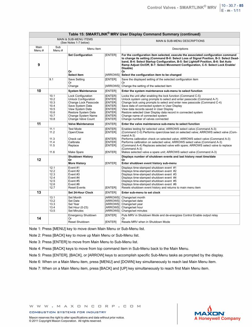
Control Valves - SMARTLINK® MRV 10 - 30.7 - 85E - m - 1/11
Note 1: Press [MENU] key to move down Main Menu or Sub-Menu list.
Note 2: Press [BACK] key to move up Main Menu or Sub-Menu list.
Note 3: Press [ENTER] to move from Main Menu to Sub-Menu list.
Note 4: Press [BACK] keys to move from top command item in Sub-Menu back to the Main Menu.
Note 5: Press [ENTER], [BACK], or [ARROW] keys to accomplish specific Sub-Menu tasks as prompted by the display.
Note 6: When on a Main Menu item, press [MENU] and [DOWN] key simultaneously to reach last Main Menu item.
Note 7: When on a Main Menu item, press [BACK] and [UP] key simultaneously to reach first Main Menu item.
Table 15: SMARTLINK® MRV User Display Command Summary (continued)MAIN & SUB-MENU ITEMS
(See Notes 1-7 below)MAIN & SUB-MENU DESCRIPTIONS
MainMenu #
SubMenu #
Menu Item Descriptions
9
Set Configuration
OrSelect Item
[ENTER]
[ARROWS]
For the configuration item selected, execute the associated configuration command to change its setting (Command B-0: Select Loss of Signal Position, B-3: Select Dead-band, B-4: Select Startup Configuration, B-5: Set Lightoff Position, B-6: Set Auto Ramp Adjust On/Off, B-7: Select Movement Configuration, C-5: Select Lock Enable/Disable)OrSelect the configuration item to be changed
9.1 Save SettingOrChange
[ENTER]
[ARROWS]
Save the displayed setting of the selected configuration item Or Change the setting of the selected item
10 System Maintenance [ENTER] Enter the system maintenance sub-menu to select function
10.110.210.310.410.510.610.710.8
Lock ConfigurationUnlock ConfigurationChange Lock PasscodeSave System DataView System DataRestore System DataChange System NameChange Valve Count
[ENTER][ENTER][ENTER][ENTER][ENTER][ENTER][ENTER][ENTER]
Locks the unit after enabling the lock function (Command C-5) Unlock system using prompts to select and enter passcode (Command A-7) Change lock using prompts to select and enter new passcode (Command C-4) Save data of connected system in User Display View data records saved in User Display Restore selected User Display data record in connected system Change name of connected system Change number of valves connected
11 Valve Maintenance [ENTER] Enter the valve maintenance sub-menu to select function
11.111.2
11.311.411.5
11.6
Test ModeOpen/Close
Check calCalibrateReplace
Make Spare
[ENTER][ENTER]
[ENTER][ENTER][ENTER]
[ENTER]
Enables testing for selected valve; ARROWS select valve (Command A-3) (Command C-0) Performs open/close test on selected valve; ARROWS select valve (Com-mand A-3) Performs calibration check on selected valve; ARROWS select valve (Command A-3) Performs calibration on selected valve; ARROWS select valve (Command A-3) (Command A-4) Replaces selected valve with spare; ARROWS select valve to replace (Command A-3) Makes selected valve a spare unit; ARROWS select valve (Command A-3)
12Shutdown HistoryOrMore History [ENTER]
Displays number of shutdown events and last history reset time/dateOrEnter shutdown event history sub-menu
12.112.212.312.412.512.612.7
Event #1Event #2Event #3Event #4Event #5Event #6Reset Events [ENTER]
Displays time-stamped shutdown event #1 Displays time-stamped shutdown event #2 Displays time-stamped shutdown event #3 Displays time-stamped shutdown event #4 Displays time-stamped shutdown event #5 Displays time-stamped shutdown event #6 Resets shutdown event history and returns to main menu item
13 Set 24-Hour Clock [ENTER] Enter sub-menu to set clock
13.113.213.313.413.5
Set MonthSet DateSet YearSet Hour (0-23)Set Minutes
[ARROWS][ARROWS][ARROWS][ARROWS][ARROWS]
Change/set monthChange/set dateChange/set yearChange/set hourChange/set minutes
14Emergency ShutdownOrReset Shutdown
[ENTER]
[ENTER]
Puts MRV in Shutdown Mode and de-energizes Control Enable output relayOrResets MRV when in Shutdown Mode
w w w . m a x o n c o r p . c o mcombustion systems for industryMaxon reserves the right to alter specifications and data without prior notice. © 2011 Copyright Maxon Corporation. All rights reserved.
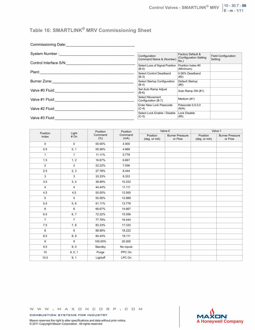
Control Valves - SMARTLINK® MRV 10 - 30.7 - 86E - m - 1/11
Table 16: SMARTLINK® MRV Commissioning Sheet
Commissioning Date:_________________________________
System Number :____________________________________
Control Interface S/N:_________________________________
Plant:_____________________________________________
Burner Zone:_______________________________________
Valve #0 Fluid:______________________________________
Valve #1 Fluid:______________________________________
Valve #2 Fluid:______________________________________
Valve #3 Fluid:______________________________________
Position Index
Light# On
Position Command
(%)
PositionCommand
(mA)
Valve-0 Valve-1
Position(deg. or mA)
Burner Pressureor Flow
Position(deg. or mA)
Burner Pressureor Flow
0 0 00.00% 4.000
0.5 0, 1 05.56% 4.889
1 1 11.11% 5.778
1.5 1, 2 16.67% 6.667
2 2 22.22% 7.556
2.5 2, 3 27.78% 8.444
3 3 33.33% 9.333
3.5 3, 4 38.89% 10.222
4 4 44.44% 11.111
4.5 4,5 50.00% 12.000
5 5 55.56% 12.889
5.5 5, 6 61.11% 13.778
6 6 66.67% 14.667
6.5 6, 7 72.22% 15.556
7 7 77.78% 16.444
7.5 7, 8 83.33% 17.333
8 8 88.89% 18.222
8.5 8, 9 94.44% 19.111
9 9 100.00% 20.000
9.5 9, 0 Standby No inputs
10 9, 0, 1 Purge PPC On
10.5 9, 1 Lightoff LPC On
ConfigurationCommand Name & (Number)
Factory Default &(Configuration Setting No.)
Field Configuration Setting
Select Loss of Signal Position (B-0)
Position Index #0(Minimum)
Select Control Deadband (B-3)
0.06% Deadband(#2)
Select Startup Configuration (B-4)
Default Startup(#0)
Set Auto Ramp Adjust (B-6)
Auto Ramp ON (#1)
Select Movement Configuration (B-7)
Medium (#1)
Enter New Lock Passcode(C-4)
Passcode 0,0,0,0(N/A)
Select Lock Enable / Disable(C-5)
Lock Disable (#0)
w w w . m a x o n c o r p . c o mcombustion systems for industryMaxon reserves the right to alter specifications and data without prior notice. © 2011 Copyright Maxon Corporation. All rights reserved.
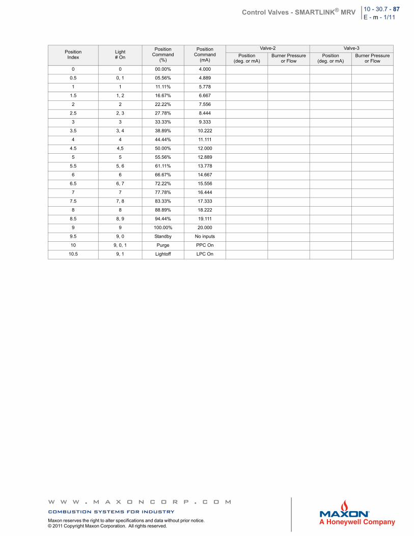
Control Valves - SMARTLINK® MRV 10 - 30.7 - 87E - m - 1/11
Position Index
Light# On
Position Command
(%)
PositionCommand
(mA)
Valve-2 Valve-3
Position(deg. or mA)
Burner Pressureor Flow
Position(deg. or mA)
Burner Pressureor Flow
0 0 00.00% 4.000
0.5 0, 1 05.56% 4.889
1 1 11.11% 5.778
1.5 1, 2 16.67% 6.667
2 2 22.22% 7.556
2.5 2, 3 27.78% 8.444
3 3 33.33% 9.333
3.5 3, 4 38.89% 10.222
4 4 44.44% 11.111
4.5 4,5 50.00% 12.000
5 5 55.56% 12.889
5.5 5, 6 61.11% 13.778
6 6 66.67% 14.667
6.5 6, 7 72.22% 15.556
7 7 77.78% 16.444
7.5 7, 8 83.33% 17.333
8 8 88.89% 18.222
8.5 8, 9 94.44% 19.111
9 9 100.00% 20.000
9.5 9, 0 Standby No inputs
10 9, 0, 1 Purge PPC On
10.5 9, 1 Lightoff LPC On
w w w . m a x o n c o r p . c o mcombustion systems for industryMaxon reserves the right to alter specifications and data without prior notice. © 2011 Copyright Maxon Corporation. All rights reserved.
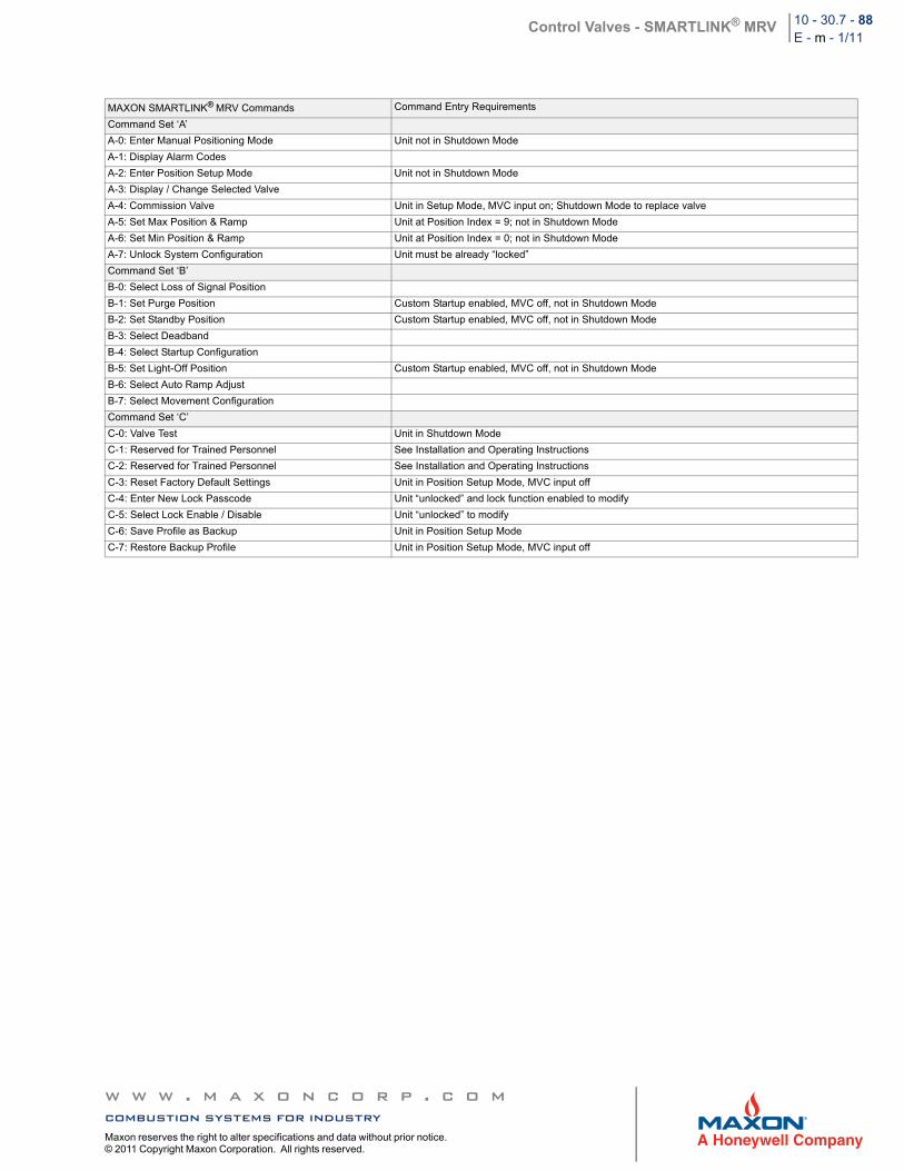
Control Valves - SMARTLINK® MRV 10 - 30.7 - 88E - m - 1/11
MAXON SMARTLINK® MRV Commands Command Entry Requirements
Command Set ‘A’
A-0: Enter Manual Positioning Mode Unit not in Shutdown Mode
A-1: Display Alarm Codes
A-2: Enter Position Setup Mode Unit not in Shutdown Mode
A-3: Display / Change Selected Valve
A-4: Commission Valve Unit in Setup Mode, MVC input on; Shutdown Mode to replace valve
A-5: Set Max Position & Ramp Unit at Position Index = 9; not in Shutdown Mode
A-6: Set Min Position & Ramp Unit at Position Index = 0; not in Shutdown Mode
A-7: Unlock System Configuration Unit must be already “locked”
Command Set ‘B’
B-0: Select Loss of Signal Position
B-1: Set Purge Position Custom Startup enabled, MVC off, not in Shutdown Mode
B-2: Set Standby Position Custom Startup enabled, MVC off, not in Shutdown Mode
B-3: Select Deadband
B-4: Select Startup Configuration
B-5: Set Light-Off Position Custom Startup enabled, MVC off, not in Shutdown Mode
B-6: Select Auto Ramp Adjust
B-7: Select Movement Configuration
Command Set ‘C’
C-0: Valve Test Unit in Shutdown Mode
C-1: Reserved for Trained Personnel See Installation and Operating Instructions
C-2: Reserved for Trained Personnel See Installation and Operating Instructions
C-3: Reset Factory Default Settings Unit in Position Setup Mode, MVC input off
C-4: Enter New Lock Passcode Unit “unlocked” and lock function enabled to modify
C-5: Select Lock Enable / Disable Unit “unlocked” to modify
C-6: Save Profile as Backup Unit in Position Setup Mode
C-7: Restore Backup Profile Unit in Position Setup Mode, MVC input off
w w w . m a x o n c o r p . c o mcombustion systems for industryMaxon reserves the right to alter specifications and data without prior notice. © 2011 Copyright Maxon Corporation. All rights reserved.