Embed Size (px)
Citation preview

More information online at bannerengineering.com 151
RO
PE P
ULL
SW
ITC
HES
E-ST
OP
BUTT
ON
S
EMERGENCY STOP DEVICES
E-Stop Buttons page 152Mechanical and optical palm buttons push to stop and • twist to release.
Modular design makes assembly and installation easy.•
Kits simplify selection and ordering.•
Rope Pull Switches page 157 Available spans range from 6 to 100 m.•
Trip and latch switch models are available. •
Minimum switch life is 1 million operations. •
Heavy-duty switch housings withstand harsh environments • and outdoor use.
Courtesy of Steven Engineering, Inc.-230 Ryan Way, South San Francisco, CA 94080-6370-Main Office: (650) 588-9200-Outside Local Area: (800) 258-9200-www.stevenengineering.com

152 More information online at bannerengineering.com
RO
PE P
ULL
SW
ITC
HES
E-ST
OP
BUTT
ON
SEMERGENCY STOP DEVICES
Opposite sidesSFS-EBM-01E2
PICO-GUARD™ Buttons work in conjunction with the PICO-GUARD Controller and other optical elements in personnel safety and equipment protection applications. The E-Stop Button is used with Banner’s plastic fiber optic cable and offers a simple, quick means of connecting and disconnecting the fiber. When paired with the PICO-GUARD Controller, the E-Stop Button meets Safety Category 4 applications (per ISO 13849-1) and is certified for use in harsh and potentially explosive environments.
Features bright red push-to-stop, twist-to-release button with • yellow background that complies with ANSI NFPA 79, IEC 60204-1 and ISO 13850 (EN 418)
Provides choice of models with fiber connections on same side or • opposite sides of enclosure
Certified to ISO 13849-1 Category 4 requirements •
Delivers easy connection for 2 mm OD (1 mm core) plastic fibers •
Accommodates up to 3 E-Stops in a series on a single channel • (all PICO-GUARD controllers have four channels)
Constructed of impact-resistant polycarbonate resin—rated IP65 •
Can be used with SFI interlocking switches in same optical loop •
Offers easy mounting and installation •
PICO-GUARD™
Fiber Optic Emergency Stop Push Buttons
ATEX, FM and CSA certified for use in Class 1 Division 1 and Zone 0 potentially explosive environment
PICO-GUARD Optical E-Stop Buttons Page 66
Fiber connection ports
Paint booths•
Paint and stain manufacturing•
Gaseous fill areas (example, • cigarette lighters)
Cosmetic and perfume manufacturing•
Film and web processing•
Chemical processing•
Battery manufacturing•
Pharmaceutical manufacturing•
Semiconductor processing•
Same sideSFS-EBM-01E1
Courtesy of Steven Engineering, Inc.-230 Ryan Way, South San Francisco, CA 94080-6370-Main Office: (650) 588-9200-Outside Local Area: (800) 258-9200-www.stevenengineering.com

More information online at bannerengineering.com 153
RO
PE P
ULL
SW
ITC
HES
E-ST
OP
BUTT
ON
S
EMERGENCY STOP DEVICES
Electromechanical palm buttons push to stop and twist to release.•
Modular design makes assembly and installation easy.•
Kits simplify selection and ordering.•
Latching design complies with ANSI NFPA 79, IEC 60204-1 and • ISO 13850 (EN 418).
Options include station enclosures, contact elements and disc labels.•
E-Stop ButtonEmergency Stop Push Buttons
E-Stop ButtonsChoice of metal or plastic •
Rugged modular construction •
Choice of normally open auxiliary • contacts and normally closed safety contacts
Positive opening safety contacts • (IEC 60947-5-1)
Emergency Stop Push Button with Enclosure
(Plastic button version shown)
Metal (top) and Plastic (bottom) buttons
ONlINE
AUTOCAD, STEP, IGES & PDF
95 mm
113 mm
78.5 mm
Courtesy of Steven Engineering, Inc.-230 Ryan Way, South San Francisco, CA 94080-6370-Main Office: (650) 588-9200-Outside Local Area: (800) 258-9200-www.stevenengineering.com
154 More information online at bannerengineering.com
RO
PE P
ULL
SW
ITC
HES
E-ST
OP
BUTT
ON
SEMERGENCY STOP DEVICES
E-Stop Push-Button Components
Models Description ProductData Sheet
8-lP2T-B6644* 22.5 mm plastic button (mounting adapter included)
111880
8-lM2T-B6644* 22.5 mm metal button (8-LM2T-AU120 mounting adapter sold separately)
8-lM2T-AU120 Metal mounting adapter
8-lM2T-C01** Normally closed (NC) positively driven contact element
8-lM2T-C10 Normally open (NO) auxiliary contact element
8-l2PP-1A5One-button enclosure—control stations have wire entry through the top or bottom; IP65 rating
8-lM2T-AU115† 60 mm diameter, non-adhesive plastic legend with “Emergency Stop” inscription
* Twist to release, mechanical latching ISO 13850 (EN 418) compliant. Diameter 40 mm (without mounting adapter).** Direct (positive) opening operation per IEC/EN 60947-5-1. † Additional E-Stop background labels are available (see p/n 121976).
E-Stop Push-Button Kits
Models E-Stop Button Contacts
Enclosure legend
SSA-EBM-02l
Metal
2 NC
No 111880SSA-EBM-11l 1 NC & 1 NO
SSA-EBM-12l 2 NC & 1 NO
NC = Normally Closed Contact, NO = Normally Open Contact More onnext page
Courtesy of Steven Engineering, Inc.-230 Ryan Way, South San Francisco, CA 94080-6370-Main Office: (650) 588-9200-Outside Local Area: (800) 258-9200-www.stevenengineering.com

More information online at bannerengineering.com 155
RO
PE P
ULL
SW
ITC
HES
E-ST
OP
BUTT
ON
S
EMERGENCY STOP DEVICES
E-Stop Push-Button Kits
Models E-Stop Button Contacts
Enclosure legend
SSA-EBP- 02l
Plastic
2 NC
No YesSSA-EBP-11l 1 NC & 1 NO
SSA-EBP-12l 2 NC & 1 NO
SSA-EBM-02E
Metal
2 NC
Yes YesSSA-EBM-11E 1 NC & 1 NO
SSA-EBM-12E 2 NC & 1 NO
SSA-EBP-02E
Plastic
2 NC
Yes YesSSA-EBP-11E 1 NC & 1 NO
SSA-EBP-12E 2 NC & 1 NO
NC = Normally Closed Contact, NO = Normally Open Contact
(cont’d)
Courtesy of Steven Engineering, Inc.-230 Ryan Way, South San Francisco, CA 94080-6370-Main Office: (650) 588-9200-Outside Local Area: (800) 258-9200-www.stevenengineering.com
156 More information online at bannerengineering.com
RO
PE P
ULL
SW
ITC
HES
E-ST
OP
BUTT
ON
SEMERGENCY STOP DEVICES
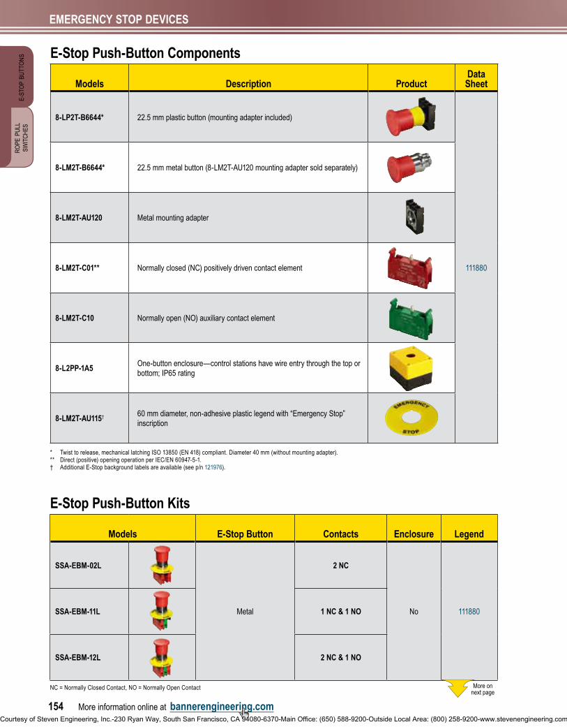
E-Stop Push-Button SpecificationsMechanical life 300,000 operations
Operating Force 0.8 kg
Mounting Adapter Plastic button: The adapter is fixed to the mounting surface by means of incorporated screws (Tmax
= 0.6 Nm)Metal button: The adapter is fixed to the mounting surface by means of incorporated screws (T
max = 0.8 Nm)
Construction Plastic parts: Polyamide and polycarbonateMetal parts: Aluminum and zinc alloy
Environmental Rating IP65; NEMA 4, 13
Operating Temperature -25° to +60° C
Certifications
Contact SpecificationsEuropean Rating Utilization categories: AC15 and DC13
Ui = 690V ac
Ith = 10A
UL designation = A 600 Q600
Mechanical life 1,000,000 operations
Connections (1 or 2) 12 AWG (2.5 mm2) maximum wire size
Construction Polyamide and polycarbonate
Environmental Rating IP20
Operating Temperature -25° to +60° C
Certifications
EMERGENCY STOP DEVICES
Courtesy of Steven Engineering, Inc.-230 Ryan Way, South San Francisco, CA 94080-6370-Main Office: (650) 588-9200-Outside Local Area: (800) 258-9200-www.stevenengineering.com

More information online at bannerengineering.com 157
RO
PE P
ULL
SW
ITC
HES
E-ST
OP
BUTT
ON
S
EMERGENCY STOP DEVICES
Rope Pull SwitchesMultiple locationEmergency Shutdown
RP-RM83 Models Page 157
RP-LS42 Models 158
RP-QM72/QMT72 Models 159
RP-LM40 Models 160
RP-QM90 Models 160
Components for Wire Rope Assembly 161
ROPE PULL
PAGE 161
Available spans range from 6 to 100 m.•
Trip and latch switch models are available. •
Minimum switch life is 1-million operations. •
Heavy-duty switch housings withstand harsh environments and • outdoor use.
Switch activates if the rope is pulled, becomes loose or breaks.•
RP-RM83 Rope Pull Switches ONlINE
AUTOCAD, STEP, IGES & PDF
Latch design•
Rope span up to 75 meters•
Manual reset with E-Stop button•
Tension indicator•
Additional solid-state auxiliary output • for remote tension monitoring
Extra contacts for switch monitoring•
Positive opening safety contacts • (IEC 60947-5-1)
See page • 161 for wire rope components
RP-RM83F-75lT.. and RP-RM83F-38lT.. Models
90.0 mm53.0 mm
237.0 mm
RP-RM83F-75lR.. and RP-RM83F-38lR.. Models
53.0 mm
185.0 mm
90.0 mm
GlANDS
PAGE 187
COMPONENTS
Courtesy of Steven Engineering, Inc.-230 Ryan Way, South San Francisco, CA 94080-6370-Main Office: (650) 588-9200-Outside Local Area: (800) 258-9200-www.stevenengineering.com

158 More information online at bannerengineering.com
RO
PE P
ULL
SW
ITC
HES
E-ST
OP
BUTT
ON
SEMERGENCY STOP DEVICES
RP-lS42 Series, 42 mm
Model ActuationMax. Rope
lengthSafety
Contacts**AuxiliaryContact
Action/ Contact State**
Contact Config. &Switch Diagram
Data Sheet
RP-lS42F-75lLatch (Rope Pulled)
75 m2 NC
in
normal rope tension
2 NOin
normal rope tension
Safety Auxiliary rope is pulled
open open closed closedrope breaks
open open closed closed
SD031 (p. 218)
67709RP-lS42F-75lE
RP-lS42F-75lFnormal rope tension
Run Position
rope is pulled
Cable Pulled
rope breaks
Cable Break NC = Normally Closed Contact, NO = Normally Open Contact** See data sheet or Contact Configuration and Switching Diagrams for more information/clarification.
RP-lS42 Rope Pull Switches
RP-lS42F-75lF Model
Rope span up to 75 meters •
Manual reset•
Extra contacts for switch • monitoring
Latch design •
Tension indicator•
Model with E-stop button • and quick rope fixing and tensioning
42 mm wide at base •
Insulated device • (IEC 60947-5-1)
Positive opening safety • contacts (IEC 60947-5-1)
See page • 161 for wire rope components
RP-lS42F-75l Model
45.0 mm
244.0 mm
42.0 mm
RP-lS42F-75lE Model(with E-Stop Button)
294.0 mm
42.0 mm
45.0 mm 45.0 mm
42.0 mm
294.0 mm
ONlINE
AUTOCAD, STEP, IGES & PDF
RP-RM83 Series, 83 mmModels
ActuationSafety
Contacts**AuxiliaryContacts
Action/ Contact State**
Contact Config. &
Switch DiagramData Sheet
Max. Rope length 75 m
Max. Rope length 38 m
RP-RM83F-75lTE RP-RM83F-38lTELatch(Rope Pulled)
2 NCin
normal rope tension
2 NOin
normal rope tension Safety Auxiliary rope is pulled
open open closed closedrope breaks
open open closed closed
SD029 & SD030 (p. 217)
141245RP-RM83F-75lRE RP-RM83F-38lRE
RP-RM83F-75lT RP-RM83F-38lT
RP-RM83F-75lR RP-RM83F-38lRnormal rope tension
Run Position
rope is pulled
Cable Pulled
rope breaks
Cable Break NC = Normally Closed Contact, NO = Normally Open Contact
** See data sheet or Contact Configuration and Switching Diagrams for more information/clarification.
Courtesy of Steven Engineering, Inc.-230 Ryan Way, South San Francisco, CA 94080-6370-Main Office: (650) 588-9200-Outside Local Area: (800) 258-9200-www.stevenengineering.com

More information online at bannerengineering.com 159
RO
PE P
ULL
SW
ITC
HES
E-ST
OP
BUTT
ON
S
EMERGENCY STOP DEVICES
RP-QM72/QMT72 Rope Pull Switches
RP-QM72 Models
Five latch-design models from • which to choose
Models with 6, 12 or 20 m • rope spans
Manual reset•
Models with extra contacts for • monitoring or for dual-channel input to a safety device
Protective earth terminal • (IEC 60947-1)
Tension indicator•
82 mm wide at base •
Positive opening safety contacts • (IEC 60947-5-1)
See page • 161 for wire rope components
RP-QM72/QMT72 Series, 72 mm
Model ActuationMax. Rope
lengthSafety
Contacts*AuxiliaryContact
Action/ Contact State*
Contact Config. &Switch Diagram
Data Sheet
RP-QM72D-6l
Latch (Rope Pulled)
6 m
2 NCin
normal rope tension
—
Safety rope is pulled
open closedrope breaks
closed open
SD032 (p. 218)
62084
RP-QM72D-12l 12 mSD033 (p. 218)
RP-QMT72D-20l 20 mSD034 (p. 218)
RP-QMT72F-12l 12 m4 NC
in
normal rope tension
—
Safety rope is pulled
open open closed closedrope breaks
closed closed open open
SD035 (p. 218)
RP-QMT72E-12l 12 m2 NC
in
normal rope tension
1 NOin
normal rope tension Safety Auxiliary rope is pulled
open closed closedrope breaks
closed open open
SD036 (p. 218)
normal rope tension
Run Position
rope is pulled
Cable Pulled
rope breaks
Cable Break NC = Normally Closed Contact* Jumper Contacts together for use in a single-channel E-stop application. See data sheet or Contact Configuration and Switching Diagrams for more information/clarification.
RP-QMT72 Models
69.0 mm
82.0 mm
181.5 mm
142.0 mm
ONlINE
AUTOCAD, STEP, IGES & PDF
Courtesy of Steven Engineering, Inc.-230 Ryan Way, South San Francisco, CA 94080-6370-Main Office: (650) 588-9200-Outside Local Area: (800) 258-9200-www.stevenengineering.com
160 More information online at bannerengineering.com
RO
PE P
ULL
SW
ITC
HES
E-ST
OP
BUTT
ON
SEMERGENCY STOP DEVICES
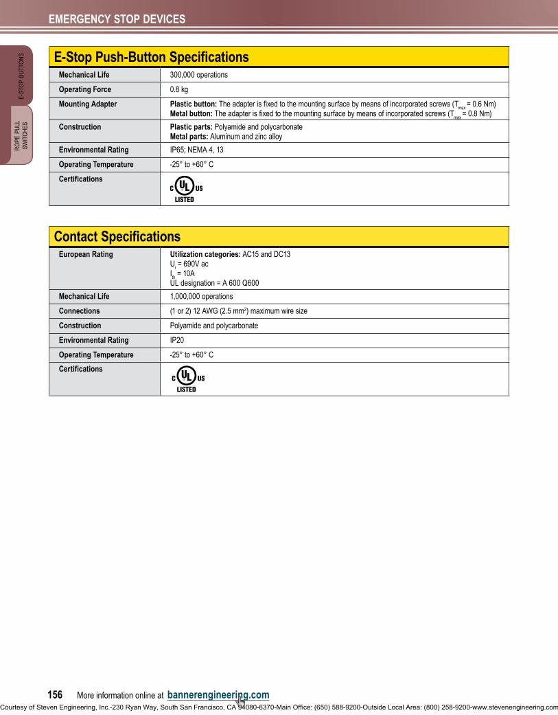
RP-QM90 Rope Pull SwitchLatch design•
Rope span up to 100 m, with switch in center •
Manual reset•
Extra contacts for switch monitoring•
Protective earth terminal (IEC 60947-1) •
90 mm wide at base •
Positive opening safety contact • (IEC 60947-5-1)
See page • 161 for wire rope components
RP-QM90 Model
90.0 mm
137.0 mm
206.0 mm
RP-QM90 Series, 90 mm
Model Actuation
Max. Rope
lengthSafety
Contacts**AuxiliaryContacts
Action/ Contact State**
Contact Config. &Switch Diagram
Data Sheet
RP-QM90F-100lLatch (Rope Pulled)
100 m2 NC
in
normal rope tension
2 NOin
normal rope tension Safety Auxiliary rope is pulled
open open closed closedrope breaks
open open closed closed
SD039 (p. 219)
62086
normal rope tension
Run Position
rope is pulled
Cable Pulled
rope breaks
Cable Break NC = Normally Closed Contact, NO = Normally Open Contact** See data sheet or Contact Configuration and Switching Diagrams for more information/clarification.
ONlINE
AUTOCAD, STEP, IGES & PDF
RP-lM40 Rope Pull SwitchesLimit-switch style• Rope span up to 6 meters • Trip and latch models • Protective earth terminal • (IEC 60947-1) Standard limit switch housing (EN 50041) • Rugged metal housing• 40 mm wide at base• Positive opening safety contacts • (IEC 60947-5-1) See page • 161 for wire rope components
ONlINE
AUTOCAD, STEP, IGES & PDF
37.5 mm
124.5 mm
40.0 mm
RP-lM40D-6 Model
147.5 mm
RP-lM40D-6l Model
37.5 mm40.0 mm
RP-lM40 Series, 40 mm
Model ActuationMax. Rope
lengthSafety
Contact*AuxiliaryContact
Action/Contact State*
Contact Config. &Switch Diagram
Data Sheet
RP-lM40D-6 Trip
6 m2 NC
in
normal rope tension
—
rope is pulled
open closedrope breaks
closed open
SD037 (p. 219)
62082
RP-lM40D-6l LatchSD038 (p. 219)normal rope tension
Run Position
rope is pulled
Cable Pulled
rope breaks
Cable Break NC = Normally Closed Contact
* Jumper Contacts together for use in a single-channel E-stop application. See data sheet or Contact Configuration and Switching Diagrams for more information/clarification.
Courtesy of Steven Engineering, Inc.-230 Ryan Way, South San Francisco, CA 94080-6370-Main Office: (650) 588-9200-Outside Local Area: (800) 258-9200-www.stevenengineering.com

More information online at bannerengineering.com 161
RO
PE P
ULL
SW
ITC
HES
E-ST
OP
BUTT
ON
S
EMERGENCY STOP DEVICES
Components for Wire Rope Assembly
ModelsPackageQuantity Description Used With
Wire
Rop
es
RPA-C1-10 10 m2 mm steel wire rope with 0.5 mm red PVC jacket (unterminated)
RP-LM40 models•
RP-RM83 modules•RPA-C1-20 20 m
RPA-C1-100 100 m
RPA-C2-10 10 m
3 mm steel wire rope with 0.5 mm red PVC jacket (unterminated)
• RP-LS42 models• RP-QM72/QMT72 models• RP-RM83 models
RPA-C2-20 20 m
RPA-C2-50 50 m
RPA-C2-80 80 m
RPA-C3-20 20 m 4 mm steel wire rope with 0.5 mm red PVC jacket (unterminated)
• RP-QM90 models RP-RM83 modules•RPA-C3-100 100 m
Thim
bles
RPA-T1-4 4 pcs Thimble for 2 mm wire rope • RP-LM40 models
RPA-T2-4 4 pcs Thimble for 3 mm wire rope• RP-LS42 models• RP-QM72/QMT72 models• RP-RM83 models
RPA-T3-4 4 pcs Thimble for 4 mm wire rope • RP-QM90 models
Cla
mps
RPA-CC1-4 4 pcs Clamp for 2 mm wire rope • RP-LM40 models
RPA-CC2-4 4 pcs Clamp for 3 mm wire rope• RP-LS42 models• RP-QM72/QMT72 models• RP-RM83 models
RPA-CC3-4 4 pcs Clamp for 4 mm wire rope • RP-QM90 models
Turn
buck
les
RPA-TA1-1 1 pc #4 Turnbuckle
• RP-LM40 models• RP-LS42 models• RP-QM72/QMT72 models• RP-RM83 models
RPA-TA2-1 1 pc #5 Turnbuckle • RP-QM90 models
Eye
Bol
ts
RPA-EB1-1 1 pc 1/4" - 20 Eye bolt (3″ bolt shaft)
• RP-LM40 models• RP-LS42 models• RP-QM72/QMT72 models• RP-RM83 models
RPA-EB2-1 1 pc 5/16" - 18 Eye bolt (3″ bolt shaft) • RP-QM90 models
Pulle
ys
RPA-P1-1
1 pcRPA-P1-1Pulley for in-line use
RPA-DP1-1Pulley for corner turns (90-180°)
• RP-LM40 models• RP-LS42 models• RP-QM72/QMT72 models• RP-RM83 models• RP-QM90 models
Tens
ioni
ng S
prin
gs
RPA-S1-1 1 pc Tensioning Spring #1 • RP-QM90 models
RPA-S2-1 1 pc Tensioning Spring #2 • RP-QM90 models
RPA-S3-1 1 pc Tensioning Spring #3• RP-LS42 models• RP-RM83 models
RPA-S5-1 1 pc Tensioning Spring #5• RP-LS42 models• RP-RM83 models
RPA-S4-1 1 pc Tensioning spring assembly with built-in eye bolt, cable thimble, clamp, tensioning and overload protection
• RP-RM83 models
RPA-S6-1 1 pc • RP-RM83 models
Term
inal
Cov
er
SI-lS42-COVER Replacement terminal cover • RP-LS42 models
RPA-DP1-1
Courtesy of Steven Engineering, Inc.-230 Ryan Way, South San Francisco, CA 94080-6370-Main Office: (650) 588-9200-Outside Local Area: (800) 258-9200-www.stevenengineering.com

162 More information online at bannerengineering.com
RO
PE P
ULL
SW
ITC
HES
E-ST
OP
BUTT
ON
SEMERGENCY STOP DEVICES
Rope Pull Switches SpecificationsContact Rating 10A @ 24V ac, 10A @ 110V ac, 6A @ 230V ac, 6A @ 24V dc
2.5 kV max. transient toleranceNEMA A300 P300
Monitoring Solid-StateOutput Rating
Rated operational voltage: Ue= 10 to 30V dc
Rated operational current: Ie= 50 mA
Utilization category: DC13Protected against reverse polarity and short circuit.
European Rating RP-RM83 models: Utilization categories: AC15 and DC13 U
i= 250V ac, I
th= 10A
All others: Utilization categories: AC15 and DC13 U
i= 500V ac, I
th= 10A
RP-RM83 models (40-60 Hz)U
e
V Ie/AC-15
AIe/DC-13
A120 6 0.55240 3 0.27
All others (40-60 Hz)U
e
V Ie/AC-15
AIe/DC-13
A24 10 6110 10 1230 6 0.4
Contact Material Silver-nickel alloy
Maximum Switching Speed RP-RM83 models: 20 operations per minute All others: 50 operations per minute
Recommended Rope Size 40 mm models: 2 mm diameter steel rope42 & 72 mm models: 3 mm diameter steel rope83 mm modles: 2-5 mm diameter steel rope90 mm models: 4 mm diameter steel rope
Maximum Rope Pull length RP-lM40D-6/6l and RP-QM72D-6l: 6 mRP-lS42F-75l/75lE/75lF: 75 mRP-QM72D-12l: 12 mRP-QMT72D-20l: 20 mRP-QMT72E-12l and RP-QMT72F-12l: 12 mRP-RM83F-75lTE/lT/lRE/lR: 75 mRP-RM83F-38lTE/lT/lR/lRE: 38 mRP-QM90F-100l: 100 mm; equal lengths up to 50 m on either side of switch
Short Circuit Protection RP-RM83 models: 6 amp Slow Blow, 10 amp Fast BlowAll others: 10 amp Slow Blow, 15 amp Fast Blow.Recommended external fusing or overload protection.
Mechanical life 1 million operations
Wire Connections Screw terminals with pressure plates accept the following wire sizes –Stranded and solid: 20 AWG (0.5 mm2) to 16 AWG (1.5 mm2) for one wireStranded: 20 AWG (0.5 mm2) to 18 AWG (1.0 mm2) for two wires
Cable Entry M20 x 1.5 threaded entranceAdapter supplied to convert M20 x 1.5 to ½" - 14 NPT threaded entrance
Construction RP-lS42F-75l/75lE/75lF: High-impact thermoplastic housing; zinc die-cast actuatorAll others: Aluminum alloy die cast
Environmental Rating RP-lS42F and RP-RM83F models: NEMA 4; IEC IP67All other models: NEMA 4; IP65
Operating Temperature RP-lS42F-75l/75lE/75lF: -25° to +70° C All other models: -30° to +80° C
Weight RP-lM40D-6: 0.22 Kg RP-lM40D-6l: 0.26 KgRP-lS42F-75l: 0.48 Kg RP-lS42F-75lE and RP-lS42F-75lF: 0.65 KgRP-QM72D-6l: 0.49 Kg RP-QM72D-12l: 0.52 KgRP-QMT72D-20l, RP-QMT72E-12l and RP-QMT72F-12l: 0.64 KgRP-QM90F-100l: 3.8 KgRP-RM83F-75lT and RP-RM83F-75lTE: 1 Kg RP-RM83F-75lR and RP-RM83F-75lRE: 0.77 KgRP-RM83F-38lT and RP83FlT8: 1Kg RP-RM83F-38lR and RP-RM83F-38lRE: 0.77 Kg
Certifications
Contact Configurations and Switching Diagrams
RP-lM40 models: SD037 & SD038 (p. 219)RP-lS42 models: SD031 (p. 218)RP-QM72/QMT72 models: SD032, SD033, SD034, SD035 & SD036 (p. 218)RP-RM83 models: SD029 & SD030 (p. 217)RP-QM90 models: SD039 (p. 219)
Courtesy of Steven Engineering, Inc.-230 Ryan Way, South San Francisco, CA 94080-6370-Main Office: (650) 588-9200-Outside Local Area: (800) 258-9200-www.stevenengineering.com


![SUUNTO AMBIT2 R 1 - drms3v40st3o6.cloudfront.net€¦ · 4 USING BUTTONS Suunto Ambit2 R has five buttons which allow you to access all the features. [Start Stop]: • access the](https://img.pdfslide.net/doc/110x75/5ec3fa5fbe55e42e4f4f2b49/suunto-ambit2-r-1-4-using-buttons-suunto-ambit2-r-has-five-buttons-which-allow.jpg)