Embed Size (px)
Citation preview
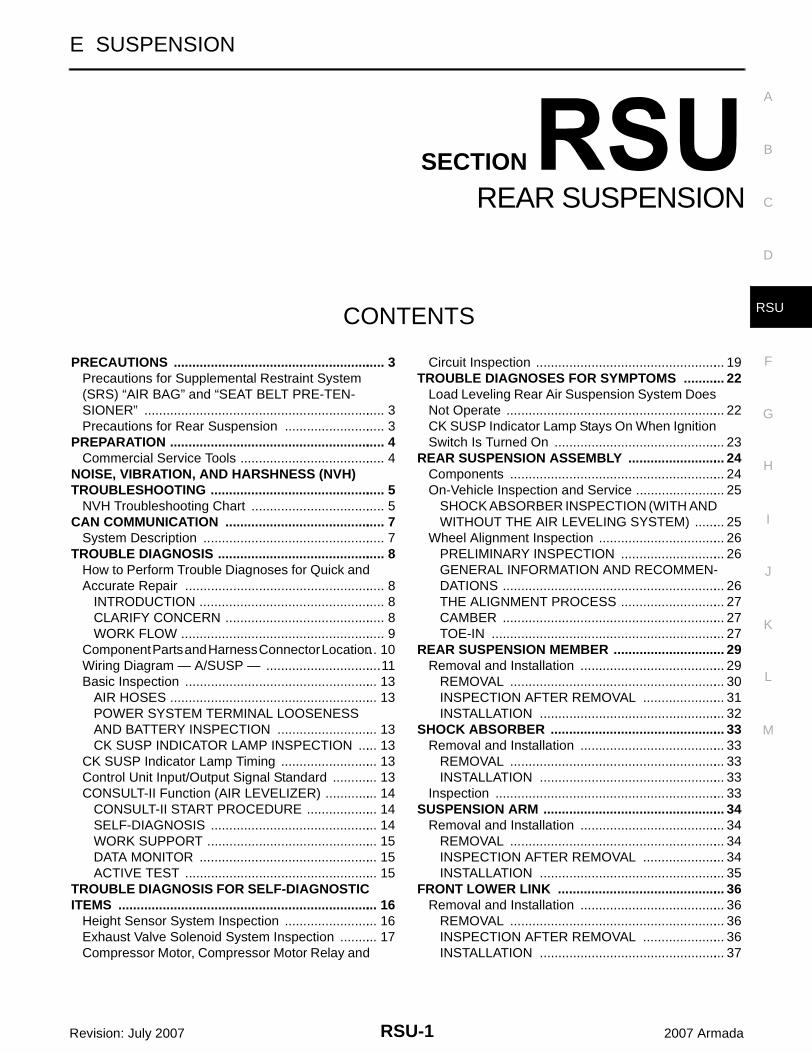
RSU-1
REAR SUSPENSION
E SUSPENSION
CONTENTS
C
D
F
G
H
I
J
K
L
M
SECTION
A
B
RSU
Revision: July 2007 2007 Armada
PRECAUTIONS .......................................................... 3Precautions for Supplemental Restraint System (SRS) “AIR BAG” and “SEAT BELT PRE-TEN-SIONER” .................................................................. 3Precautions for Rear Suspension ............................ 3
PREPARATION ........................................................... 4Commercial Service Tools ........................................ 4
NOISE, VIBRATION, AND HARSHNESS (NVH) TROUBLESHOOTING ................................................ 5
NVH Troubleshooting Chart ..................................... 5CAN COMMUNICATION ............................................ 7
System Description .................................................. 7TROUBLE DIAGNOSIS .............................................. 8
How to Perform Trouble Diagnoses for Quick and Accurate Repair ....................................................... 8
INTRODUCTION ................................................... 8CLARIFY CONCERN ............................................ 8WORK FLOW ........................................................ 9
Component Parts and Harness Connector Location ... 10Wiring Diagram — A/SUSP — ................................11Basic Inspection ..................................................... 13
AIR HOSES ......................................................... 13POWER SYSTEM TERMINAL LOOSENESS AND BATTERY INSPECTION ............................ 13CK SUSP INDICATOR LAMP INSPECTION ...... 13
CK SUSP Indicator Lamp Timing ........................... 13Control Unit Input/Output Signal Standard ............. 13CONSULT-II Function (AIR LEVELIZER) ............... 14
CONSULT-II START PROCEDURE .................... 14SELF-DIAGNOSIS .............................................. 14WORK SUPPORT ............................................... 15DATA MONITOR ................................................. 15ACTIVE TEST ..................................................... 15
TROUBLE DIAGNOSIS FOR SELF-DIAGNOSTIC ITEMS ....................................................................... 16
Height Sensor System Inspection .......................... 16Exhaust Valve Solenoid System Inspection ........... 17Compressor Motor, Compressor Motor Relay and
Circuit Inspection .................................................... 19TROUBLE DIAGNOSES FOR SYMPTOMS ............ 22
Load Leveling Rear Air Suspension System Does Not Operate ............................................................ 22CK SUSP Indicator Lamp Stays On When Ignition Switch Is Turned On ............................................... 23
REAR SUSPENSION ASSEMBLY ........................... 24Components ........................................................... 24On-Vehicle Inspection and Service ......................... 25
SHOCK ABSORBER INSPECTION (WITH AND WITHOUT THE AIR LEVELING SYSTEM) ......... 25
Wheel Alignment Inspection ................................... 26PRELIMINARY INSPECTION ............................. 26GENERAL INFORMATION AND RECOMMEN-DATIONS ............................................................. 26THE ALIGNMENT PROCESS ............................. 27CAMBER ............................................................. 27TOE-IN ................................................................ 27
REAR SUSPENSION MEMBER ............................... 29Removal and Installation ........................................ 29
REMOVAL ........................................................... 30INSPECTION AFTER REMOVAL ....................... 31INSTALLATION ................................................... 32
SHOCK ABSORBER ................................................ 33Removal and Installation ........................................ 33
REMOVAL ........................................................... 33INSTALLATION ................................................... 33
Inspection ............................................................... 33SUSPENSION ARM .................................................. 34
Removal and Installation ........................................ 34REMOVAL ........................................................... 34INSPECTION AFTER REMOVAL ....................... 34INSTALLATION ................................................... 35
FRONT LOWER LINK .............................................. 36Removal and Installation ........................................ 36
REMOVAL ........................................................... 36INSPECTION AFTER REMOVAL ....................... 36INSTALLATION ................................................... 37
RSU-2Revision: July 2007 2007 Armada
REAR LOWER LINK & COIL SPRING ..................... 38Removal and Installation ........................................ 38
REMOVAL ........................................................... 38INSPECTION AFTER REMOVAL ........................ 39INSTALLATION .................................................... 39
STABILIZER BAR ..................................................... 40Removal and Installation ........................................ 40
REMOVAL ........................................................... 40INSPECTION AFTER REMOVAL ........................ 40INSTALLATION .................................................... 40
REAR LOAD LEVELING AIR SUSPENSION COM-PRESSOR ASSEMBLY ............................................ 41
Removal and Installation ........................................ 41REMOVAL ........................................................... 41INSTALLATION .................................................... 42
HEIGHT SENSOR .....................................................43Removal and Installation .........................................43
REMOVAL ............................................................43INSTALLATION ....................................................44
CONTROL UNIT ........................................................45Removal and Installation .........................................45
REMOVAL ............................................................45INSTALLATION ....................................................45
Initialization Procedure ............................................45SERVICE DATA AND SPECIFICATIONS (SDS) ......46
Wheel Alignment (Unladen*1 ) ................................46Ball Joint .................................................................46
Wheelarch Height (Unladen*1 ) ...............................47
PRECAUTIONS
RSU-3
C
D
F
G
H
I
J
K
L
M
A
B
RSU
Revision: July 2007 2007 Armada
PRECAUTIONS PFP:00001
Precautions for Supplemental Restraint System (SRS) “AIR BAG” and “SEAT BELT PRE-TENSIONER” EES002HG
The Supplemental Restraint System such as “AIR BAG” and “SEAT BELT PRE-TENSIONER”, used alongwith a front seat belt, helps to reduce the risk or severity of injury to the driver and front passenger for certaintypes of collision. This system includes seat belt switch inputs and dual stage front air bag modules. The SRSsystem uses the seat belt switches to determine the front air bag deployment, and may only deploy one frontair bag, depending on the severity of a collision and whether the front occupants are belted or unbelted.Information necessary to service the system safely is included in the SRS and SB section of this Service Man-ual.WARNING:● To avoid rendering the SRS inoperative, which could increase the risk of personal injury or death
in the event of a collision which would result in air bag inflation, all maintenance must be per-formed by an authorized NISSAN/INFINITI dealer.
● Improper maintenance, including incorrect removal and installation of the SRS, can lead to per-sonal injury caused by unintentional activation of the system. For removal of Spiral Cable and AirBag Module, see the SRS section.
● Do not use electrical test equipment on any circuit related to the SRS unless instructed to in thisService Manual. SRS wiring harnesses can be identified by yellow and/or orange harnesses orharness connectors.
Precautions for Rear Suspension EES002HH
● When installing the rubber bushings, the final tightening must be done under unladen condition and withthe tires on level ground. Oil will shorten the life of the rubber bushings, so wipe off any spilled oil immedi-ately.
● Unladen condition means the fuel tank, engine coolant and lubricants are at the full specification. Thespare tire, jack, hand tools, and mats are in their designated positions.
● After installing suspension components, check the wheel alignment.● Caulking nuts are not reusable. Always use new caulking nuts for installation. New caulking nuts are pre-
oiled, do not apply any additional lubrication.
RSU-4
PREPARATION
Revision: July 2007 2007 Armada
PREPARATION PFP:00002
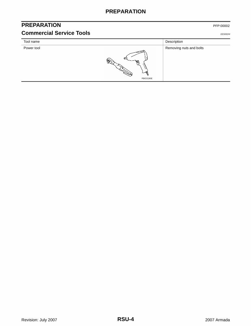
Commercial Service Tools EES002HI
Tool name Description
Power tool Removing nuts and bolts
PBIC0190E
NOISE, VIBRATION, AND HARSHNESS (NVH) TROUBLESHOOTING
RSU-5
C
D
F
G
H
I
J
K
L
M
A
B
RSU
Revision: July 2007 2007 Armada
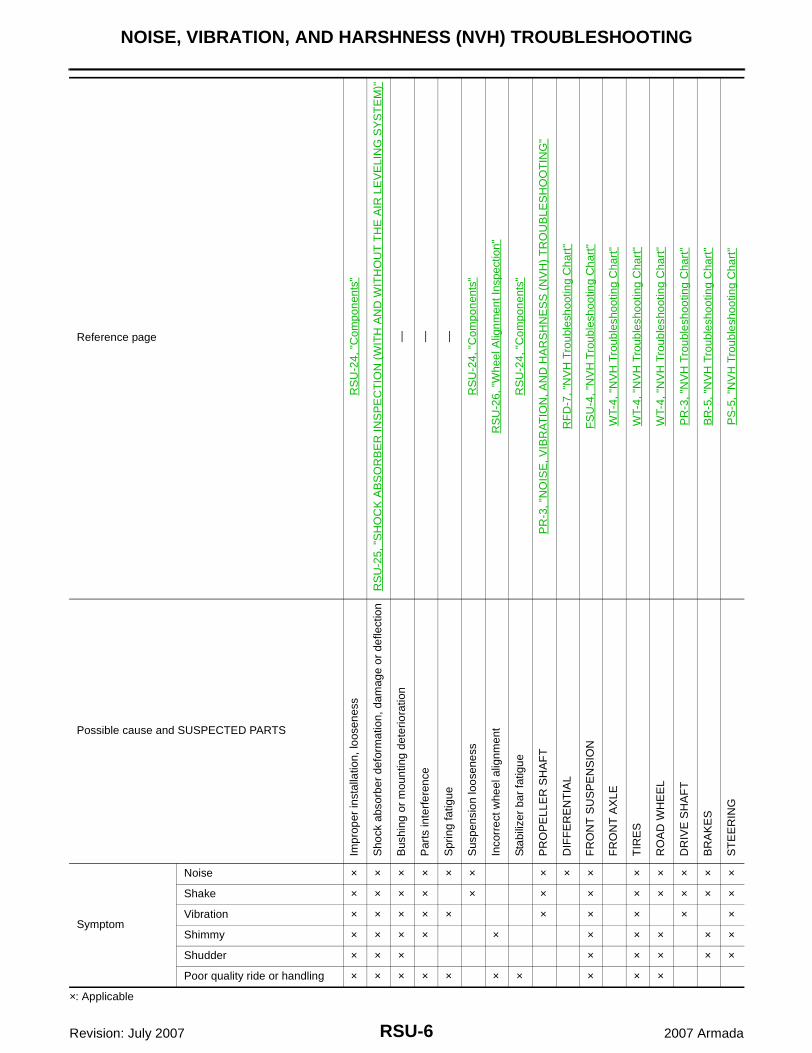
NOISE, VIBRATION, AND HARSHNESS (NVH) TROUBLESHOOTING PFP:00003
NVH Troubleshooting Chart EES002HJ
Use chart below to help you find the cause of the symptom. If necessary, repair or replace these parts.
RSU-6
NOISE, VIBRATION, AND HARSHNESS (NVH) TROUBLESHOOTING
Revision: July 2007 2007 Armada
×: Applicable
Reference page
RS
U-2
4, "
Com
pone
nts"
RS
U-2
5, "
SH
OC
K A
BS
OR
BE
R IN
SP
EC
TIO
N (
WIT
H A
ND
WIT
HO
UT
TH
E A
IR L
EV
ELI
NG
SY
ST
EM
)"
— — —
RS
U-2
4, "
Com
pone
nts"
RS
U-2
6, "
Whe
el A
lignm
ent I
nspe
ctio
n"
RS
U-2
4, "
Com
pone
nts"
PR
-3, "
NO
ISE
, VIB
RA
TIO
N, A
ND
HA
RS
HN
ES
S (
NV
H)
TR
OU
BLE
SH
OO
TIN
G"
RF
D-7
, "N
VH
Tro
uble
shoo
ting
Cha
rt"
FS
U-4
, "N
VH
Tro
uble
shoo
ting
Cha
rt"
WT-
4, "
NV
H T
roub
lesh
ootin
g C
hart
"
WT-
4, "
NV
H T
roub
lesh
ootin
g C
hart
"
WT-
4, "
NV
H T
roub
lesh
ootin
g C
hart
"
PR
-3, "
NV
H T
roub
lesh
ootin
g C
hart
"
BR
-5, "
NV
H T
roub
lesh
ootin
g C
hart
"
PS
-5, "
NV
H T
roub
lesh
ootin
g C
hart
"Possible cause and SUSPECTED PARTS
Impr
oper
inst
alla
tion,
loos
enes
s
Sho
ck a
bsor
ber
defo
rmat
ion,
dam
age
or d
efle
ctio
n
Bus
hing
or
mou
ntin
g de
terio
ratio
n
Par
ts in
terf
eren
ce
Spr
ing
fatig
ue
Sus
pens
ion
loos
enes
s
Inco
rrec
t whe
el a
lignm
ent
Sta
biliz
er b
ar fa
tigue
PR
OP
ELL
ER
SH
AF
T
DIF
FE
RE
NT
IAL
FR
ON
T S
US
PE
NS
ION
FR
ON
T A
XLE
TIR
ES
RO
AD
WH
EE
L
DR
IVE
SH
AF
T
BR
AK
ES
ST
EE
RIN
G
Symptom
Noise × × × × × × × × × × × × × ×
Shake × × × × × × × × × × × ×
Vibration × × × × × × × × × ×
Shimmy × × × × × × × × × ×
Shudder × × × × × × × ×
Poor quality ride or handling × × × × × × × × × ×
CAN COMMUNICATION
RSU-7
C
D
F
G
H
I
J
K
L
M
A
B
RSU
Revision: July 2007 2007 Armada
CAN COMMUNICATION PFP:23710
System Description EES002HK
Refer to LAN-4, "CAN Communication System" .
RSU-8
TROUBLE DIAGNOSIS
Revision: July 2007 2007 Armada
TROUBLE DIAGNOSIS PFP:00000
How to Perform Trouble Diagnoses for Quick and Accurate Repair EES002HL
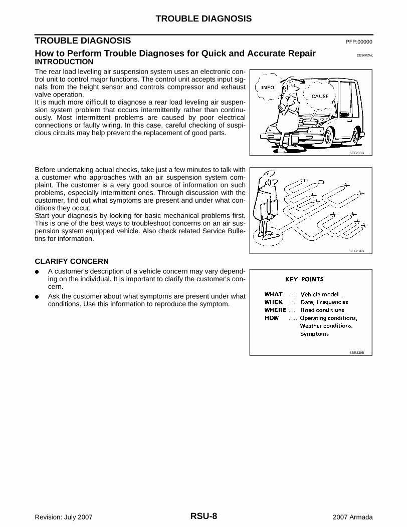
INTRODUCTIONThe rear load leveling air suspension system uses an electronic con-trol unit to control major functions. The control unit accepts input sig-nals from the height sensor and controls compressor and exhaustvalve operation.It is much more difficult to diagnose a rear load leveling air suspen-sion system problem that occurs intermittently rather than continu-ously. Most intermittent problems are caused by poor electricalconnections or faulty wiring. In this case, careful checking of suspi-cious circuits may help prevent the replacement of good parts.
Before undertaking actual checks, take just a few minutes to talk witha customer who approaches with an air suspension system com-plaint. The customer is a very good source of information on suchproblems, especially intermittent ones. Through discussion with thecustomer, find out what symptoms are present and under what con-ditions they occur.Start your diagnosis by looking for basic mechanical problems first.This is one of the best ways to troubleshoot concerns on an air sus-pension system equipped vehicle. Also check related Service Bulle-tins for information.
CLARIFY CONCERN● A customer's description of a vehicle concern may vary depend-
ing on the individual. It is important to clarify the customer's con-cern.
● Ask the customer about what symptoms are present under whatconditions. Use this information to reproduce the symptom.
SEF233G
SEF234G
SBR339B
TROUBLE DIAGNOSIS
RSU-9
C
D
F
G
H
I
J
K
L
M
A
B
RSU
Revision: July 2007 2007 Armada
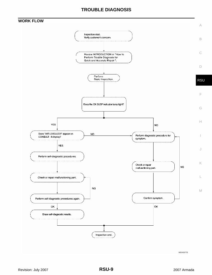
WORK FLOW
WEIA0077E
RSU-10
TROUBLE DIAGNOSIS
Revision: July 2007 2007 Armada
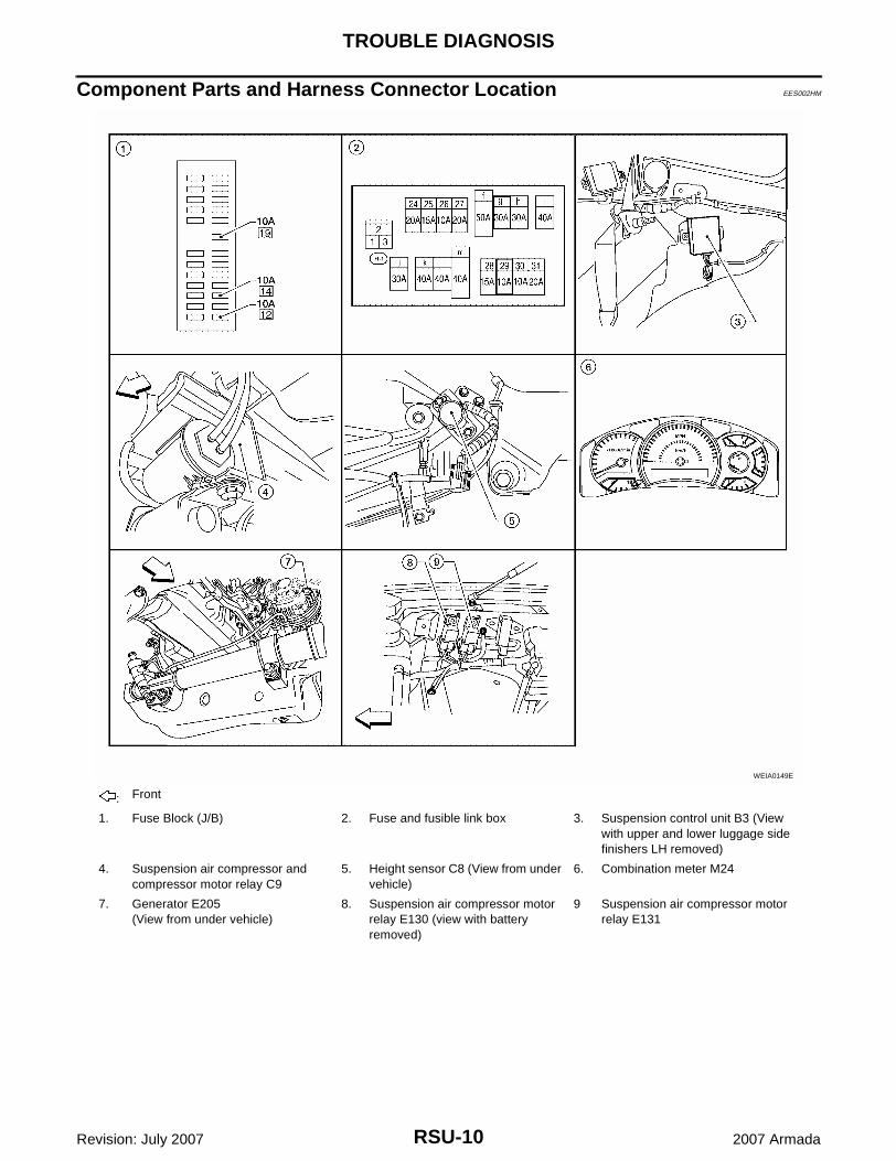
Component Parts and Harness Connector Location EES002HM
: Front
1. Fuse Block (J/B) 2. Fuse and fusible link box 3. Suspension control unit B3 (View with upper and lower luggage side finishers LH removed)
4. Suspension air compressor and compressor motor relay C9
5. Height sensor C8 (View from under vehicle)
6. Combination meter M24
7. Generator E205(View from under vehicle)
8. Suspension air compressor motor relay E130 (view with battery removed)
9 Suspension air compressor motor relay E131
WEIA0149E
TROUBLE DIAGNOSIS
RSU-11
C
D
F
G
H
I
J
K
L
M
A
B
RSU
Revision: July 2007 2007 Armada
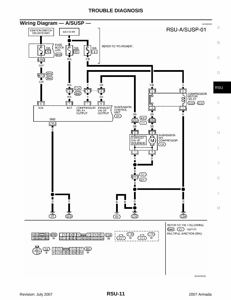
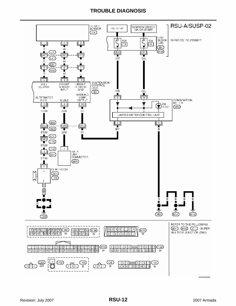
Wiring Diagram — A/SUSP — EES002HN
WEWA0053E
RSU-12
TROUBLE DIAGNOSIS
Revision: July 2007 2007 Armada
WEWA0069E
TROUBLE DIAGNOSIS
RSU-13
C
D
F
G
H
I
J
K
L
M
A
B
RSU
Revision: July 2007 2007 Armada
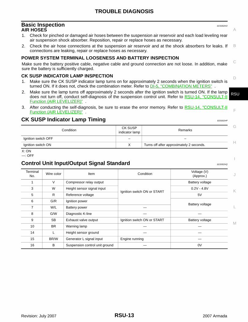
Basic Inspection EES002HO
AIR HOSES1. Check for pinched or damaged air hoses between the suspension air reservoir and each load leveling rear
air suspension shock absorber. Reposition, repair or replace hoses as necessary.2. Check the air hose connections at the suspension air reservoir and at the shock absorbers for leaks. If
connections are leaking, repair or replace hoses as necessary.
POWER SYSTEM TERMINAL LOOSENESS AND BATTERY INSPECTIONMake sure the battery positive cable, negative cable and ground connection are not loose. In addition, makesure the battery is sufficiently charged.
CK SUSP INDICATOR LAMP INSPECTION1. Make sure the CK SUSP indicator lamp turns on for approximately 2 seconds when the ignition switch is
turned ON. If it does not, check the combination meter. Refer to DI-5, "COMBINATION METERS" .2. Make sure the lamp turns off approximately 2 seconds after the ignition switch is turned ON. If the lamp
does not turn off, conduct self-diagnosis of the suspension control unit. Refer to RSU-14, "CONSULT-IIFunction (AIR LEVELIZER)" .
3. After conducting the self-diagnosis, be sure to erase the error memory. Refer to RSU-14, "CONSULT-IIFunction (AIR LEVELIZER)" .
CK SUSP Indicator Lamp Timing EES002HP
X: ON—: OFF
Control Unit Input/Output Signal Standard EES002HQ
ConditionCK SUSP
indicator lampRemarks
Ignition switch OFF – –
Ignition switch ON X Turns off after approximately 2 seconds.
Terminal No.
Wire color Item ConditionVoltage (V)(Approx.)
1 V Compressor relay output
Ignition switch ON or START
Battery voltage
3 W Height sensor signal input 0.2V - 4.8V
5 R Reference voltage 5V
6 G/R Ignition powerBattery voltage
7 W/L Battery power —
8 G/W Diagnostic K-line — —
9 SB Exhaust valve output Ignition switch ON or START Battery voltage
10 BR Warning lamp — —
14 L Height sensor ground — —
15 BR/W Generator L signal input Engine running —
16 B Suspension control unit ground — 0V
RSU-14
TROUBLE DIAGNOSIS
Revision: July 2007 2007 Armada
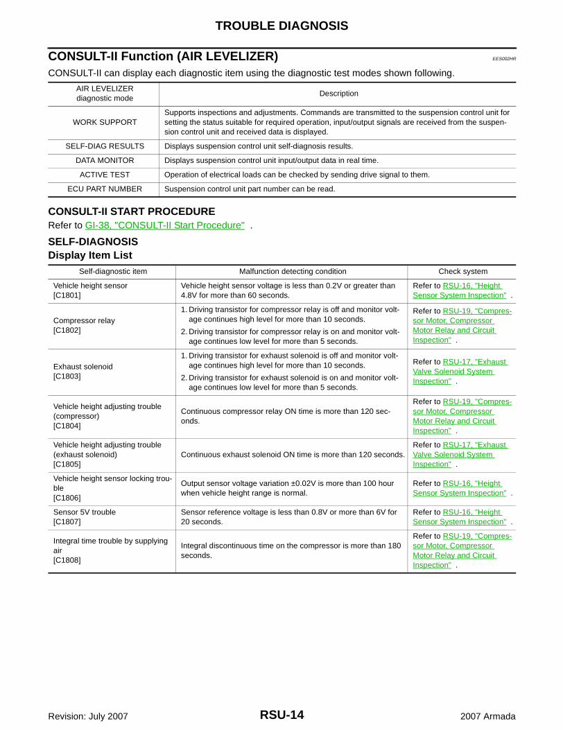
CONSULT-II Function (AIR LEVELIZER) EES002HR
CONSULT-II can display each diagnostic item using the diagnostic test modes shown following.
CONSULT-II START PROCEDURERefer to GI-38, "CONSULT-II Start Procedure" .
SELF-DIAGNOSISDisplay Item List
AIR LEVELIZERdiagnostic mode
Description
WORK SUPPORTSupports inspections and adjustments. Commands are transmitted to the suspension control unit for setting the status suitable for required operation, input/output signals are received from the suspen-sion control unit and received data is displayed.
SELF-DIAG RESULTS Displays suspension control unit self-diagnosis results.
DATA MONITOR Displays suspension control unit input/output data in real time.
ACTIVE TEST Operation of electrical loads can be checked by sending drive signal to them.
ECU PART NUMBER Suspension control unit part number can be read.
Self-diagnostic item Malfunction detecting condition Check system
Vehicle height sensor[C1801]
Vehicle height sensor voltage is less than 0.2V or greater than 4.8V for more than 60 seconds.
Refer to RSU-16, "Height Sensor System Inspection" .
Compressor relay[C1802]
1. Driving transistor for compressor relay is off and monitor volt-age continues high level for more than 10 seconds.
2. Driving transistor for compressor relay is on and monitor volt-age continues low level for more than 5 seconds.
Refer to RSU-19, "Compres-sor Motor, Compressor Motor Relay and Circuit Inspection" .
Exhaust solenoid[C1803]
1. Driving transistor for exhaust solenoid is off and monitor volt-age continues high level for more than 10 seconds.
2. Driving transistor for exhaust solenoid is on and monitor volt-age continues low level for more than 5 seconds.
Refer to RSU-17, "Exhaust Valve Solenoid System Inspection" .
Vehicle height adjusting trouble (compressor)[C1804]
Continuous compressor relay ON time is more than 120 sec-onds.
Refer to RSU-19, "Compres-sor Motor, Compressor Motor Relay and Circuit Inspection" .
Vehicle height adjusting trouble (exhaust solenoid)[C1805]
Continuous exhaust solenoid ON time is more than 120 seconds.Refer to RSU-17, "Exhaust Valve Solenoid System Inspection" .
Vehicle height sensor locking trou-ble[C1806]
Output sensor voltage variation ±0.02V is more than 100 hour when vehicle height range is normal.
Refer to RSU-16, "Height Sensor System Inspection" .
Sensor 5V trouble[C1807]
Sensor reference voltage is less than 0.8V or more than 6V for 20 seconds.
Refer to RSU-16, "Height Sensor System Inspection" .
Integral time trouble by supplying air[C1808]
Integral discontinuous time on the compressor is more than 180 seconds.
Refer to RSU-19, "Compres-sor Motor, Compressor Motor Relay and Circuit Inspection" .
TROUBLE DIAGNOSIS
RSU-15
C
D
F
G
H
I
J
K
L
M
A
B
RSU
Revision: July 2007 2007 Armada
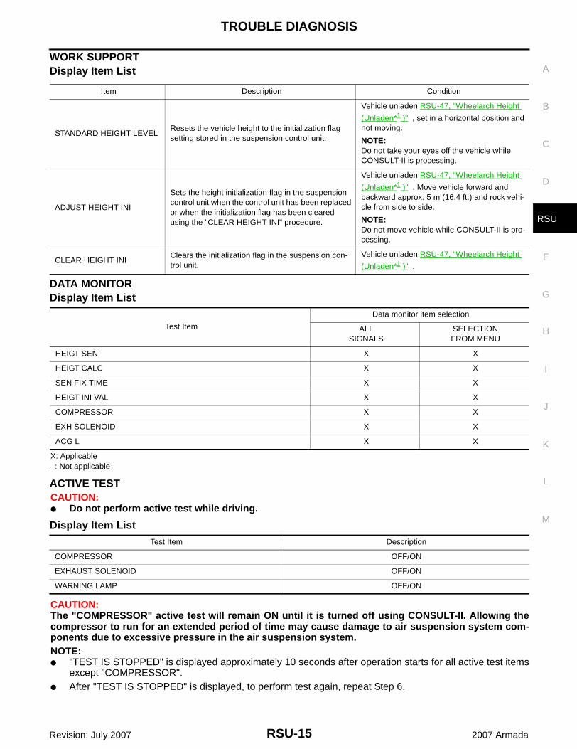
WORK SUPPORTDisplay Item List
DATA MONITORDisplay Item List
X: Applicable–: Not applicable
ACTIVE TESTCAUTION:● Do not perform active test while driving.
Display Item List
CAUTION:The "COMPRESSOR" active test will remain ON until it is turned off using CONSULT-II. Allowing thecompressor to run for an extended period of time may cause damage to air suspension system com-ponents due to excessive pressure in the air suspension system.NOTE:● "TEST IS STOPPED" is displayed approximately 10 seconds after operation starts for all active test items
except "COMPRESSOR".● After "TEST IS STOPPED" is displayed, to perform test again, repeat Step 6.
Item Description Condition
STANDARD HEIGHT LEVELResets the vehicle height to the initialization flag setting stored in the suspension control unit.
Vehicle unladen RSU-47, "Wheelarch Height
(Unladen*1 )" , set in a horizontal position and not moving.
NOTE:Do not take your eyes off the vehicle while CONSULT-II is processing.
ADJUST HEIGHT INI
Sets the height initialization flag in the suspension control unit when the control unit has been replaced or when the initialization flag has been cleared using the "CLEAR HEIGHT INI" procedure.
Vehicle unladen RSU-47, "Wheelarch Height
(Unladen*1 )" . Move vehicle forward and backward approx. 5 m (16.4 ft.) and rock vehi-cle from side to side.
NOTE:Do not move vehicle while CONSULT-II is pro-cessing.
CLEAR HEIGHT INIClears the initialization flag in the suspension con-trol unit.
Vehicle unladen RSU-47, "Wheelarch Height
(Unladen*1 )" .
Test Item
Data monitor item selection
ALLSIGNALS
SELECTIONFROM MENU
HEIGT SEN X X
HEIGT CALC X X
SEN FIX TIME X X
HEIGT INI VAL X X
COMPRESSOR X X
EXH SOLENOID X X
ACG L X X
Test Item Description
COMPRESSOR OFF/ON
EXHAUST SOLENOID OFF/ON
WARNING LAMP OFF/ON
RSU-16
TROUBLE DIAGNOSIS FOR SELF-DIAGNOSTIC ITEMS
Revision: July 2007 2007 Armada
TROUBLE DIAGNOSIS FOR SELF-DIAGNOSTIC ITEMS PFP:00000
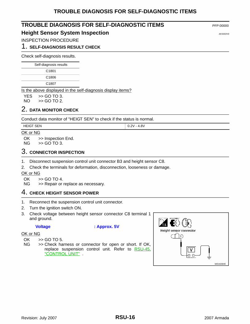
Height Sensor System Inspection EES002HS
INSPECTION PROCEDURE
1. SELF-DIAGNOSIS RESULT CHECK
Check self-diagnosis results.
Is the above displayed in the self-diagnosis display items?YES >> GO TO 3.NO >> GO TO 2.
2. DATA MONITOR CHECK
Conduct data monitor of "HEIGT SEN" to check if the status is normal.
OK or NGOK >> Inspection End.NG >> GO TO 3.
3. CONNECTOR INSPECTION
1. Disconnect suspension control unit connector B3 and height sensor C8.2. Check the terminals for deformation, disconnection, looseness or damage.OK or NGOK >> GO TO 4.NG >> Repair or replace as necessary.
4. CHECK HEIGHT SENSOR POWER
1. Reconnect the suspension control unit connector.2. Turn the ignition switch ON.3. Check voltage between height sensor connector C8 terminal 1
and ground.
OK or NGOK >> GO TO 5.NG >> Check harness or connector for open or short. If OK,
replace suspension control unit. Refer to RSU-45,"CONTROL UNIT" .
Self-diagnosis results
C1801
C1806
C1807
HEIGT SEN 0.2V - 4.8V
Voltage : Approx. 5V
WEIA0084E
TROUBLE DIAGNOSIS FOR SELF-DIAGNOSTIC ITEMS
RSU-17
C
D
F
G
H
I
J
K
L
M
A
B
RSU
Revision: July 2007 2007 Armada
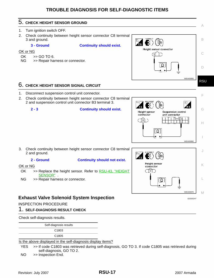
5. CHECK HEIGHT SENSOR GROUND
1. Turn ignition switch OFF.2. Check continuity between height sensor connector C8 terminal
3 and ground.
OK or NGOK >> GO TO 6.NG >> Repair harness or connector.
6. CHECK HEIGHT SENSOR SIGNAL CIRCUIT
1. Disconnect suspension control unit connector.2. Check continuity between height sensor connector C8 terminal
2 and suspension control unit connector B3 terminal 3.
3. Check continuity between height sensor connector C8 terminal2 and ground.
OK or NGOK >> Replace the height sensor. Refer to RSU-43, "HEIGHT
SENSOR" .NG >> Repair harness or connector.
Exhaust Valve Solenoid System Inspection EES002HT
INSPECTION PROCEDURE
1. SELF-DIAGNOSIS RESULT CHECK
Check self-diagnosis results.
Is the above displayed in the self-diagnosis display items?YES >> If code C1803 was retrieved during self-diagnosis, GO TO 3. If code C1805 was retrieved during
self-diagnosis, GO TO 2.NO >> Inspection End.
3 - Ground Continuity should exist.
WEIA0085E
2 - 3 Continuity should exist.
WEIA0086E
2 - Ground Continuity should not exist.
WEIA0087E
Self-diagnosis results
C1803
C1805
RSU-18
TROUBLE DIAGNOSIS FOR SELF-DIAGNOSTIC ITEMS
Revision: July 2007 2007 Armada
2. CHECK SYSTEM OPERATION
1. Load vehicle to standard laden condition (with driver, front passenger, 2 passengers in second row seatsand no cargo).
2. Conduct active test of "COMPRESSOR" to raise vehicle ride height to +20mm.CAUTION:The "COMPRESSOR" active test will remain ON until it is turned off using CONSULT-II. Allowingthe compressor to run for an extended period of time may cause damage to air suspension sys-tem components due to excessive pressure in the air suspension system.
3. Return the rear load leveling air suspension system to normal operating mode.4. Check self-diagnostic results.Is code C1805 displayed again?YES >> GO TO 3.NO >> Inspection End.
3. CONNECTOR INSPECTION
1. Turn ignition switch OFF.2. Disconnect suspension control unit connector B3 and suspension air compressor C9.3. Check the terminals for deformation, disconnection, looseness or damage.OK or NGOK >> If code C1805 was retrieved during self-diagnosis, GO TO 4. If code C1803 was retrieved during
self-diagnosis, GO TO 6.NG >> Repair or replace as necessary.
4. AIR HOSE INSPECTION
Inspect for pinched or damaged air hoses between the suspension air reservoir and each load leveling rear airsuspension shock absorber.OK or NGOK >> GO TO 5.NG >> Repair or replace as necessary.
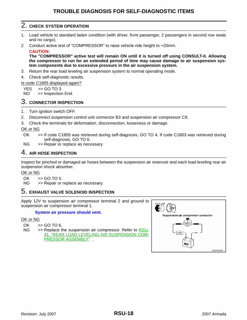
5. EXHAUST VALVE SOLENOID INSPECTION
Apply 12V to suspension air compressor terminal 2 and ground tosuspension air compressor terminal 1.
OK or NGOK >> GO TO 6.NG >> Replace the suspension air compressor. Refer to RSU-
41, "REAR LOAD LEVELING AIR SUSPENSION COM-PRESSOR ASSEMBLY" .
System air pressure should vent.
WEIA0063E
TROUBLE DIAGNOSIS FOR SELF-DIAGNOSTIC ITEMS
RSU-19
C
D
F
G
H
I
J
K
L
M
A
B
RSU
Revision: July 2007 2007 Armada
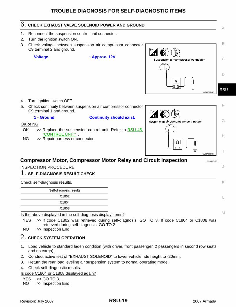
6. CHECK EXHAUST VALVE SOLENOID POWER AND GROUND
1. Reconnect the suspension control unit connector.2. Turn the ignition switch ON.3. Check voltage between suspension air compressor connector
C9 terminal 2 and ground.
4. Turn ignition switch OFF.5. Check continuity between suspension air compressor connector
C9 terminal 1 and ground.
OK or NGOK >> Replace the suspension control unit. Refer to RSU-45,
"CONTROL UNIT" .NG >> Repair harness or connector.
Compressor Motor, Compressor Motor Relay and Circuit Inspection EES002HU
INSPECTION PROCEDURE
1. SELF-DIAGNOSIS RESULT CHECK
Check self-diagnosis results.
Is the above displayed in the self-diagnosis display items?YES >> If code C1802 was retrieved during self-diagnosis, GO TO 3. If code C1804 or C1808 was
retrieved during self-diagnosis, GO TO 2.NO >> Inspection End.
2. CHECK SYSTEM OPERATION
1. Load vehicle to standard laden condition (with driver, front passenger, 2 passengers in second row seatsand no cargo).
2. Conduct active test of "EXHAUST SOLENOID" to lower vehicle ride height to -20mm.3. Return the rear load leveling air suspension system to normal operating mode.4. Check self-diagnostic results.Is code C1804 or C1808 displayed again?YES >> GO TO 3.NO >> Inspection End.
Voltage : Approx. 12V
WEIA0088E
1 - Ground Continuity should exist.
WEIA0089E
Self-diagnosis results
C1802
C1804
C1808
RSU-20
TROUBLE DIAGNOSIS FOR SELF-DIAGNOSTIC ITEMS
Revision: July 2007 2007 Armada
3. CONNECTOR INSPECTION
1. Turn ignition switch OFF.2. Disconnect suspension control unit connector B3 and suspension air compressor C9.3. Check the terminals for deformation, disconnection, looseness or damage.OK or NGOK >> If code C1804 or C1808 was retrieved during self-diagnosis, GO TO 4. If code C1802 was
retrieved during self-diagnosis, GO TO 6.NG >> Repair or replace as necessary.
4. AIR HOSE INSPECTION
Inspect for pinched or damaged air hoses between the suspension air reservoir and each load leveling rear airsuspension shock absorber.OK or NGOK >> GO TO 5.NG >> Repair or replace as necessary.
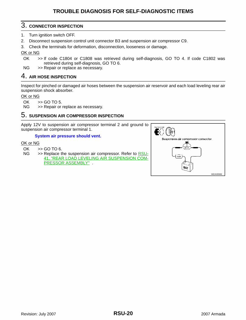
5. SUSPENSION AIR COMPRESSOR INSPECTION
Apply 12V to suspension air compressor terminal 2 and ground tosuspension air compressor terminal 1.
OK or NGOK >> GO TO 6.NG >> Replace the suspension air compressor. Refer to RSU-
41, "REAR LOAD LEVELING AIR SUSPENSION COM-PRESSOR ASSEMBLY" .
System air pressure should vent.
WEIA0066E
TROUBLE DIAGNOSIS FOR SELF-DIAGNOSTIC ITEMS
RSU-21
C
D
F
G
H
I
J
K
L
M
A
B
RSU
Revision: July 2007 2007 Armada
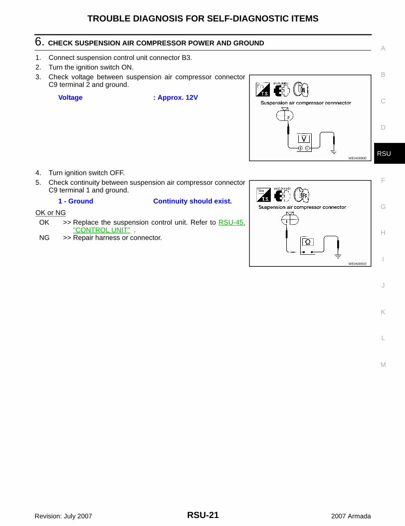
6. CHECK SUSPENSION AIR COMPRESSOR POWER AND GROUND
1. Connect suspension control unit connector B3.2. Turn the ignition switch ON.3. Check voltage between suspension air compressor connector
C9 terminal 2 and ground.
4. Turn ignition switch OFF.5. Check continuity between suspension air compressor connector
C9 terminal 1 and ground.
OK or NGOK >> Replace the suspension control unit. Refer to RSU-45,
"CONTROL UNIT" .NG >> Repair harness or connector.
Voltage : Approx. 12V
WEIA0090E
1 - Ground Continuity should exist.
WEIA0091E
RSU-22
TROUBLE DIAGNOSES FOR SYMPTOMS
Revision: July 2007 2007 Armada
TROUBLE DIAGNOSES FOR SYMPTOMS PFP:99999
Load Leveling Rear Air Suspension System Does Not Operate EES002HV
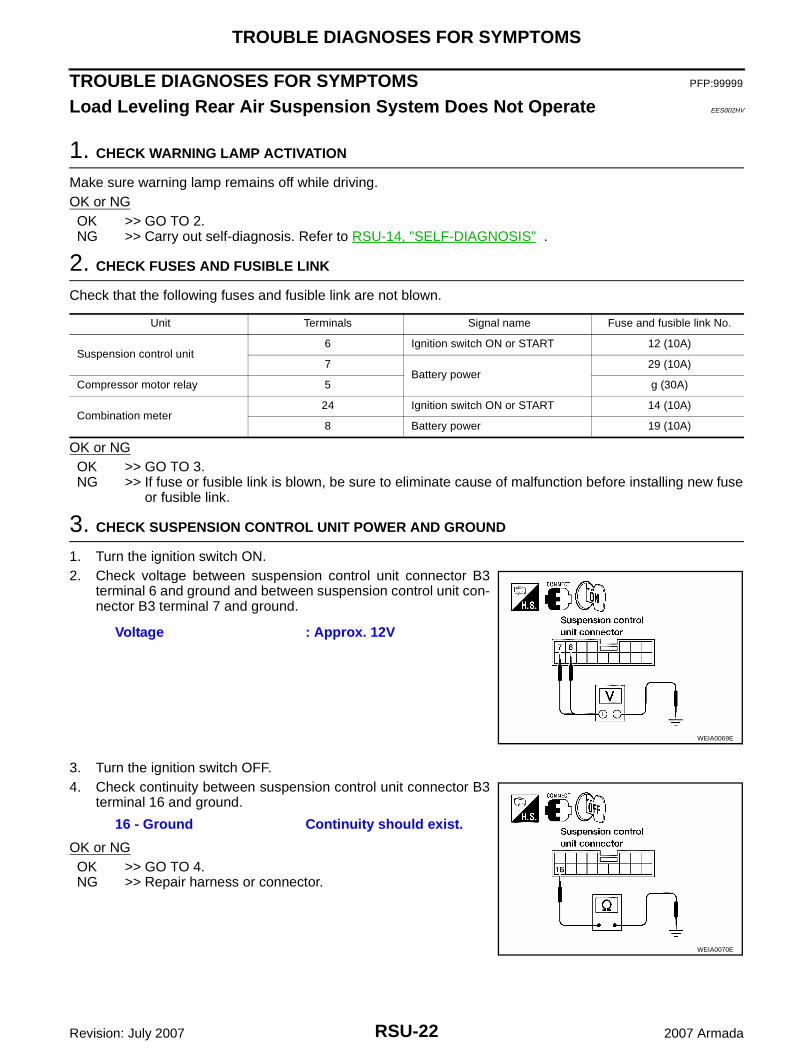
1. CHECK WARNING LAMP ACTIVATION
Make sure warning lamp remains off while driving.OK or NGOK >> GO TO 2.NG >> Carry out self-diagnosis. Refer to RSU-14, "SELF-DIAGNOSIS" .
2. CHECK FUSES AND FUSIBLE LINK
Check that the following fuses and fusible link are not blown.
OK or NGOK >> GO TO 3.NG >> If fuse or fusible link is blown, be sure to eliminate cause of malfunction before installing new fuse
or fusible link.
3. CHECK SUSPENSION CONTROL UNIT POWER AND GROUND
1. Turn the ignition switch ON.2. Check voltage between suspension control unit connector B3
terminal 6 and ground and between suspension control unit con-nector B3 terminal 7 and ground.
3. Turn the ignition switch OFF.4. Check continuity between suspension control unit connector B3
terminal 16 and ground.
OK or NGOK >> GO TO 4.NG >> Repair harness or connector.
Unit Terminals Signal name Fuse and fusible link No.
Suspension control unit6 Ignition switch ON or START 12 (10A)
7Battery power
29 (10A)
Compressor motor relay 5 g (30A)
Combination meter24 Ignition switch ON or START 14 (10A)
8 Battery power 19 (10A)
Voltage : Approx. 12V
WEIA0069E
16 - Ground Continuity should exist.
WEIA0070E
TROUBLE DIAGNOSES FOR SYMPTOMS
RSU-23
C
D
F
G
H
I
J
K
L
M
A
B
RSU
Revision: July 2007 2007 Armada
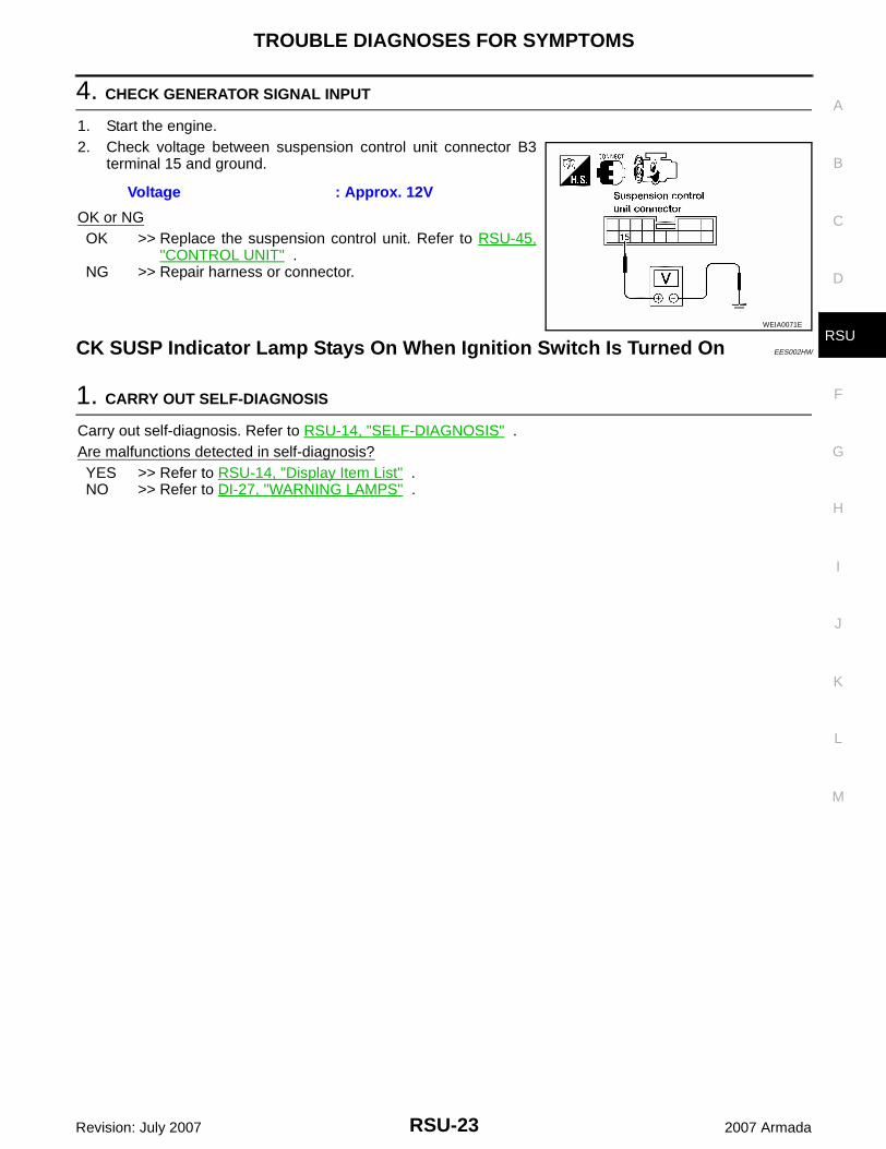
4. CHECK GENERATOR SIGNAL INPUT
1. Start the engine.2. Check voltage between suspension control unit connector B3
terminal 15 and ground.
OK or NGOK >> Replace the suspension control unit. Refer to RSU-45,
"CONTROL UNIT" .NG >> Repair harness or connector.
CK SUSP Indicator Lamp Stays On When Ignition Switch Is Turned On EES002HW
1. CARRY OUT SELF-DIAGNOSIS
Carry out self-diagnosis. Refer to RSU-14, "SELF-DIAGNOSIS" .Are malfunctions detected in self-diagnosis?YES >> Refer to RSU-14, "Display Item List" .NO >> Refer to DI-27, "WARNING LAMPS" .
Voltage : Approx. 12V
WEIA0071E
RSU-24
REAR SUSPENSION ASSEMBLY
Revision: July 2007 2007 Armada
REAR SUSPENSION ASSEMBLY PFP:55020
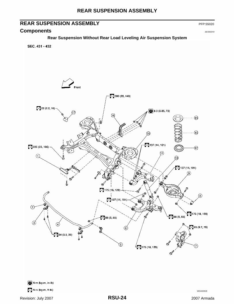
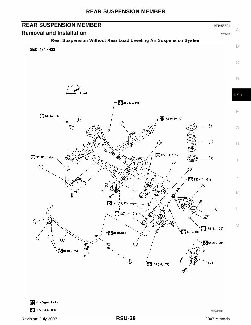
Components EES002HX
Rear Suspension Without Rear Load Leveling Air Suspension System
WEIA0092E
REAR SUSPENSION ASSEMBLY
RSU-25
C
D
F
G
H
I
J
K
L
M
A
B
RSU
Revision: July 2007 2007 Armada
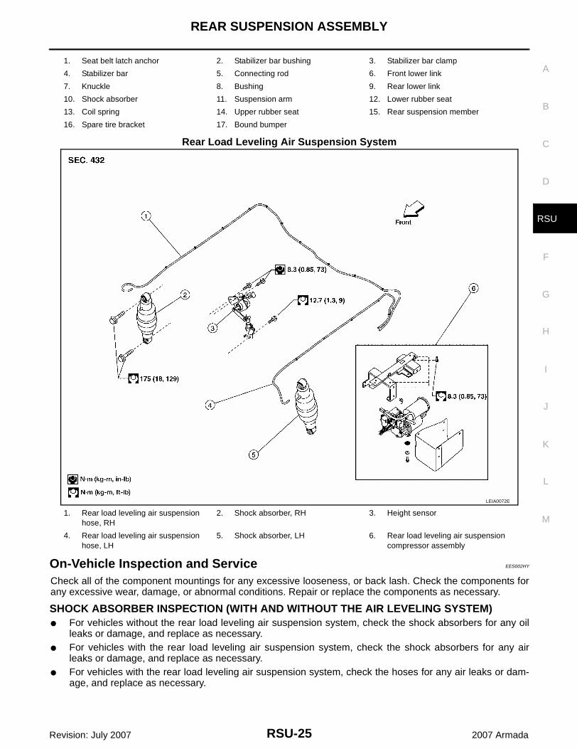
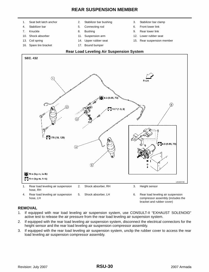
Rear Load Leveling Air Suspension System
On-Vehicle Inspection and Service EES002HY
Check all of the component mountings for any excessive looseness, or back lash. Check the components forany excessive wear, damage, or abnormal conditions. Repair or replace the components as necessary.
SHOCK ABSORBER INSPECTION (WITH AND WITHOUT THE AIR LEVELING SYSTEM)● For vehicles without the rear load leveling air suspension system, check the shock absorbers for any oil
leaks or damage, and replace as necessary.● For vehicles with the rear load leveling air suspension system, check the shock absorbers for any air
leaks or damage, and replace as necessary.● For vehicles with the rear load leveling air suspension system, check the hoses for any air leaks or dam-
age, and replace as necessary.
1. Seat belt latch anchor 2. Stabilizer bar bushing 3. Stabilizer bar clamp
4. Stabilizer bar 5. Connecting rod 6. Front lower link
7. Knuckle 8. Bushing 9. Rear lower link
10. Shock absorber 11. Suspension arm 12. Lower rubber seat
13. Coil spring 14. Upper rubber seat 15. Rear suspension member
16. Spare tire bracket 17. Bound bumper
LEIA0072E
1. Rear load leveling air suspension hose, RH
2. Shock absorber, RH 3. Height sensor
4. Rear load leveling air suspension hose, LH
5. Shock absorber, LH 6. Rear load leveling air suspension compressor assembly
RSU-26
REAR SUSPENSION ASSEMBLY
Revision: July 2007 2007 Armada
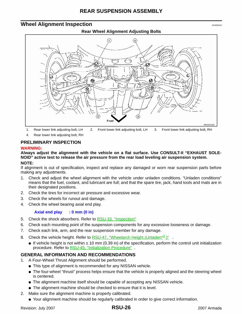
Wheel Alignment Inspection EES002HZ
Rear Wheel Alignment Adjusting Bolts
PRELIMINARY INSPECTIONWARNING:Always adjust the alignment with the vehicle on a flat surface. Use CONSULT-II “EXHAUST SOLE-NOID” active test to release the air pressure from the rear load leveling air suspension system.NOTE:If alignment is out of specification, inspect and replace any damaged or worn rear suspension parts beforemaking any adjustments.1. Check and adjust the wheel alignment with the vehicle under unladen conditions. “Unladen conditions”
means that the fuel, coolant, and lubricant are full; and that the spare tire, jack, hand tools and mats are intheir designated positions.
2. Check the tires for incorrect air pressure and excessive wear.3. Check the wheels for runout and damage.4. Check the wheel bearing axial end play.
5. Check the shock absorbers. Refer to RSU-33, "Inspection"6. Check each mounting point of the suspension components for any excessive looseness or damage.7. Check each link, arm, and the rear suspension member for any damage.
8. Check the vehicle height. Refer to RSU-47, "Wheelarch Height (Unladen*1 )" .● If vehicle height is not within ± 10 mm (0.39 in) of the specification, perform the control unit initialization
procedure. Refer to RSU-45, "Initialization Procedure" .
GENERAL INFORMATION AND RECOMMENDATIONS1. A Four-Wheel Thrust Alignment should be performed.
● This type of alignment is recommended for any NISSAN vehicle.● The four-wheel “thrust” process helps ensure that the vehicle is properly aligned and the steering wheel
is centered.● The alignment machine itself should be capable of accepting any NISSAN vehicle.● The alignment machine should be checked to ensure that it is level.
2. Make sure the alignment machine is properly calibrated.● Your alignment machine should be regularly calibrated in order to give correct information.
WEIA0102E
1. Rear lower link adjusting bolt, LH 2. Front lower link adjusting bolt, LH 3. Front lower link adjusting bolt, RH
4. Rear lower link adjusting bolt, RH
Axial end play : 0 mm (0 in)
REAR SUSPENSION ASSEMBLY
RSU-27
C
D
F
G
H
I
J
K
L
M
A
B
RSU
Revision: July 2007 2007 Armada
● Check with the manufacturer of your specific alignment machine for their recommended Service/Cali-bration Schedule.
THE ALIGNMENT PROCESSIMPORTANT: Use only the alignment specifications listed in this Service Manual. Refer to RSU-46, "WheelAlignment (Unladen*1 )" .1. When displaying the alignment settings, many alignment machines use “indicators”: (Green/red, plus or
minus, Go/No Go). Do NOT use these indicators.● The alignment specifications programmed into your alignment machine that operate these indicators
may not be correct.● This may result in an ERROR.
2. Some newer alignment machines are equipped with an optional “Rolling Compensation” method to “com-pensate” the sensors (alignment targets or head units). Do NOT use this “Rolling Compensation”method.● Use the “Jacking Compensation” method. After installing the alignment targets or head units, raise the
vehicle and rotate the wheels 1/2 turn both ways.● See Instructions in the alignment machine you are using for more information.
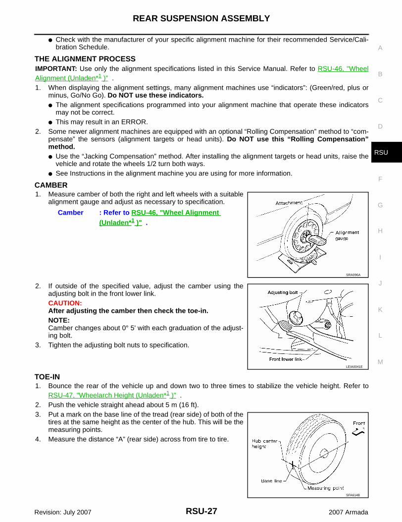
CAMBER1. Measure camber of both the right and left wheels with a suitable
alignment gauge and adjust as necessary to specification.
2. If outside of the specified value, adjust the camber using theadjusting bolt in the front lower link.CAUTION:After adjusting the camber then check the toe-in.NOTE:Camber changes about 0° 5' with each graduation of the adjust-ing bolt.
3. Tighten the adjusting bolt nuts to specification.
TOE-IN1. Bounce the rear of the vehicle up and down two to three times to stabilize the vehicle height. Refer to
RSU-47, "Wheelarch Height (Unladen*1 )" .2. Push the vehicle straight ahead about 5 m (16 ft).3. Put a mark on the base line of the tread (rear side) of both of the
tires at the same height as the center of the hub. This will be themeasuring points.
4. Measure the distance “A” (rear side) across from tire to tire.
Camber : Refer to RSU-46, "Wheel Alignment (Unladen*1 )" .
SRA096A
LEIA0041E
SFA614B
RSU-28
REAR SUSPENSION ASSEMBLY
Revision: July 2007 2007 Armada
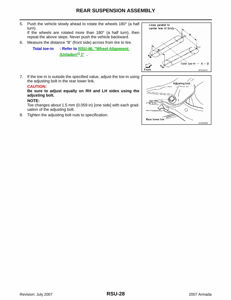
5. Push the vehicle slowly ahead to rotate the wheels 180° (a halfturn).If the wheels are rotated more than 180° (a half turn), thenrepeat the above steps. Never push the vehicle backward.
6. Measure the distance “B” (front side) across from tire to tire.
7. If the toe-in is outside the specified value, adjust the toe-in usingthe adjusting bolt in the rear lower link.CAUTION:Be sure to adjust equally on RH and LH sides using theadjusting bolt.NOTE:Toe changes about 1.5 mm (0.059 in) [one side] with each grad-uation of the adjusting bolt.
8. Tighten the adjusting bolt nuts to specification.
Total toe-in : Refer to RSU-46, "Wheel Alignment (Unladen*1 )" .
SFA234AC
LEIA0009E
REAR SUSPENSION MEMBER
RSU-29
C
D
F
G
H
I
J
K
L
M
A
B
RSU
Revision: July 2007 2007 Armada
REAR SUSPENSION MEMBER PFP:55501
Removal and Installation EES002I0
Rear Suspension Without Rear Load Leveling Air Suspension System
WEIA0092E
RSU-30
REAR SUSPENSION MEMBER
Revision: July 2007 2007 Armada
Rear Load Leveling Air Suspension System
REMOVAL1. If equipped with rear load leveling air suspension system, use CONSULT-II “EXHAUST SOLENOID”
active test to release the air pressure from the rear load leveling air suspension system.2. If equipped with the rear load leveling air suspension system, disconnect the electrical connectors for the
height sensor and the rear load leveling air suspension compressor assembly.3. If equipped with the rear load leveling air suspension system, unclip the rubber cover to access the rear
load leveling air suspension compressor assembly.
1. Seat belt latch anchor 2. Stabilizer bar bushing 3. Stabilizer bar clamp
4. Stabilizer bar 5. Connecting rod 6. Front lower link
7. Knuckle 8. Bushing 9. Rear lower link
10. Shock absorber 11. Suspension arm 12. Lower rubber seat
13. Coil spring 14. Upper rubber seat 15. Rear suspension member
16. Spare tire bracket 17. Bound bumper
LEIA0072E
1. Rear load leveling air suspension hose, RH
2. Shock absorber, RH 3. Height sensor
4. Rear load leveling air suspension hose, LH
5. Shock absorber, LH 6. Rear load leveling air suspension compressor assembly (includes the bracket and rubber cover)
REAR SUSPENSION MEMBER
RSU-31
C
D
F
G
H
I
J
K
L
M
A
B
RSU
Revision: July 2007 2007 Armada
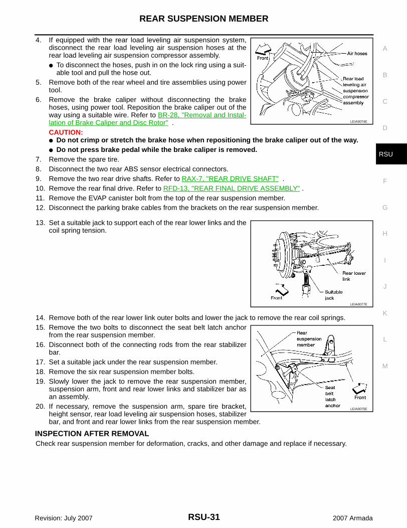
4. If equipped with the rear load leveling air suspension system,disconnect the rear load leveling air suspension hoses at therear load leveling air suspension compressor assembly.● To disconnect the hoses, push in on the lock ring using a suit-
able tool and pull the hose out.5. Remove both of the rear wheel and tire assemblies using power
tool.6. Remove the brake caliper without disconnecting the brake
hoses, using power tool. Reposition the brake caliper out of theway using a suitable wire. Refer to BR-28, "Removal and Instal-lation of Brake Caliper and Disc Rotor" .CAUTION:● Do not crimp or stretch the brake hose when repositioning the brake caliper out of the way.● Do not press brake pedal while the brake caliper is removed.
7. Remove the spare tire.8. Disconnect the two rear ABS sensor electrical connectors.9. Remove the two rear drive shafts. Refer to RAX-7, "REAR DRIVE SHAFT" .10. Remove the rear final drive. Refer to RFD-13, "REAR FINAL DRIVE ASSEMBLY" .11. Remove the EVAP canister bolt from the top of the rear suspension member.12. Disconnect the parking brake cables from the brackets on the rear suspension member.
13. Set a suitable jack to support each of the rear lower links and thecoil spring tension.
14. Remove both of the rear lower link outer bolts and lower the jack to remove the rear coil springs.15. Remove the two bolts to disconnect the seat belt latch anchor
from the rear suspension member.16. Disconnect both of the connecting rods from the rear stabilizer
bar.17. Set a suitable jack under the rear suspension member.18. Remove the six rear suspension member bolts.19. Slowly lower the jack to remove the rear suspension member,
suspension arm, front and rear lower links and stabilizer bar asan assembly.
20. If necessary, remove the suspension arm, spare tire bracket,height sensor, rear load leveling air suspension hoses, stabilizerbar, and front and rear lower links from the rear suspension member.
INSPECTION AFTER REMOVALCheck rear suspension member for deformation, cracks, and other damage and replace if necessary.
LEIA0074E
LEIA0077E
LEIA0075E
RSU-32
REAR SUSPENSION MEMBER
Revision: July 2007 2007 Armada
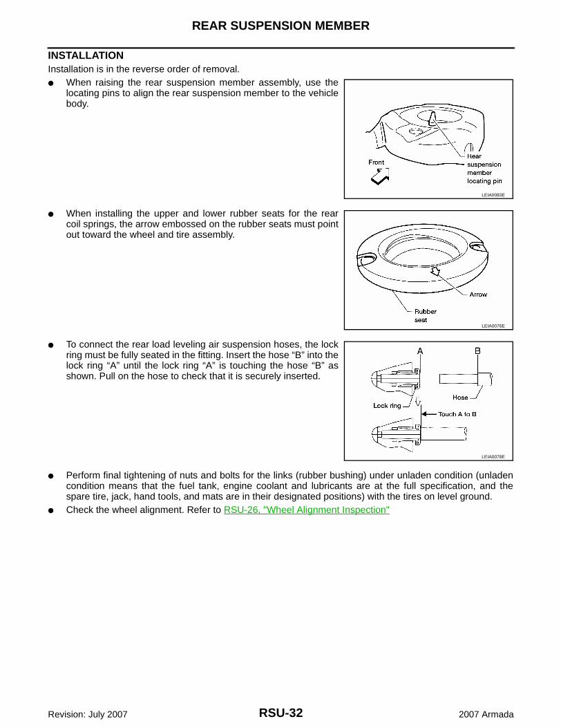
INSTALLATIONInstallation is in the reverse order of removal.● When raising the rear suspension member assembly, use the
locating pins to align the rear suspension member to the vehiclebody.
● When installing the upper and lower rubber seats for the rearcoil springs, the arrow embossed on the rubber seats must pointout toward the wheel and tire assembly.
● To connect the rear load leveling air suspension hoses, the lockring must be fully seated in the fitting. Insert the hose “B” into thelock ring “A” until the lock ring “A” is touching the hose “B” asshown. Pull on the hose to check that it is securely inserted.
● Perform final tightening of nuts and bolts for the links (rubber bushing) under unladen condition (unladencondition means that the fuel tank, engine coolant and lubricants are at the full specification, and thespare tire, jack, hand tools, and mats are in their designated positions) with the tires on level ground.
● Check the wheel alignment. Refer to RSU-26, "Wheel Alignment Inspection"
LEIA0083E
LEIA0076E
LEIA0078E
SHOCK ABSORBER
RSU-33
C
D
F
G
H
I
J
K
L
M
A
B
RSU
Revision: July 2007 2007 Armada
SHOCK ABSORBER PFP:56210
Removal and Installation EES002I1
REMOVAL1. Remove the wheel and tire assembly using power tool. Refer to WT-7, "Rotation" .2. If equipped with the rear load leveling air suspension system, use CONSULT-II "EXHAUST SOLENOID"
active test to release the air pressure from the rear load leveling air suspension system.
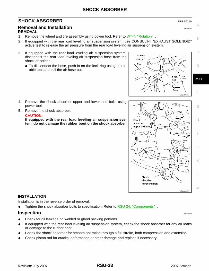
3. If equipped with the rear load leveling air suspension system,disconnect the rear load leveling air suspension hose from theshock absorber. ● To disconnect the hose, push in on the lock ring using a suit-
able tool and pull the air hose out.
4. Remove the shock absorber upper and lower end bolts usingpower tool.
5. Remove the shock absorber.CAUTION:If equipped with the rear load leveling air suspension sys-tem, do not damage the rubber boot on the shock absorber.
INSTALLATIONInstallation is in the reverse order of removal.● Tighten the shock absorber bolts to specification. Refer to RSU-24, "Components" .
Inspection EES002I2
● Check for oil leakage on welded or gland packing portions.● If equipped with the rear load leveling air suspension system, check the shock absorber for any air leaks
or damage to the rubber boot.● Check the shock absorber for smooth operation through a full stroke, both compression and extension.● Check piston rod for cracks, deformation or other damage and replace if necessary.
LEIA0081E
LEIA0082E
RSU-34
SUSPENSION ARM
Revision: July 2007 2007 Armada
SUSPENSION ARM PFP:55501
Removal and Installation EES002I3
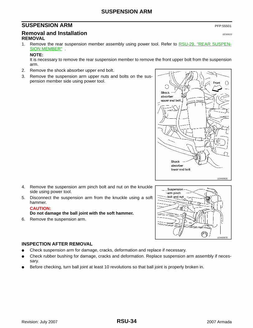
REMOVAL1. Remove the rear suspension member assembly using power tool. Refer to RSU-29, "REAR SUSPEN-
SION MEMBER" .NOTE:It is necessary to remove the rear suspension member to remove the front upper bolt from the suspensionarm.
2. Remove the shock absorber upper end bolt.3. Remove the suspension arm upper nuts and bolts on the sus-
pension member side using power tool.
4. Remove the suspension arm pinch bolt and nut on the knuckleside using power tool.
5. Disconnect the suspension arm from the knuckle using a softhammer.CAUTION:Do not damage the ball joint with the soft hammer.
6. Remove the suspension arm.
INSPECTION AFTER REMOVAL● Check suspension arm for damage, cracks, deformation and replace if necessary.● Check rubber bushing for damage, cracks and deformation. Replace suspension arm assembly if neces-
sary.● Before checking, turn ball joint at least 10 revolutions so that ball joint is properly broken in.
LEIA0082E
LEIA0087E
SUSPENSION ARM
RSU-35
C
D
F
G
H
I
J
K
L
M
A
B
RSU
Revision: July 2007 2007 Armada
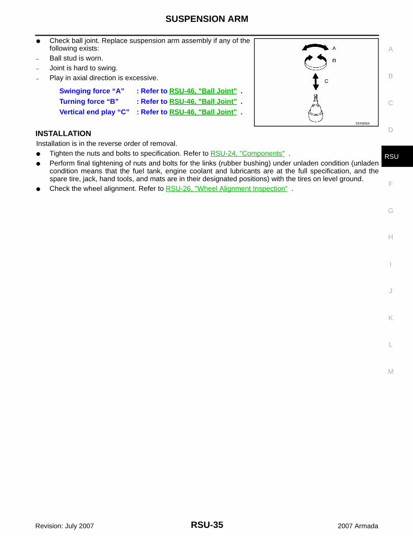
● Check ball joint. Replace suspension arm assembly if any of thefollowing exists:
– Ball stud is worn.– Joint is hard to swing.– Play in axial direction is excessive.
INSTALLATIONInstallation is in the reverse order of removal.● Tighten the nuts and bolts to specification. Refer to RSU-24, "Components" .● Perform final tightening of nuts and bolts for the links (rubber bushing) under unladen condition (unladen
condition means that the fuel tank, engine coolant and lubricants are at the full specification, and thespare tire, jack, hand tools, and mats are in their designated positions) with the tires on level ground.
● Check the wheel alignment. Refer to RSU-26, "Wheel Alignment Inspection" .
Swinging force “A” : Refer to RSU-46, "Ball Joint" .Turning force “B” : Refer to RSU-46, "Ball Joint" .Vertical end play “C” : Refer to RSU-46, "Ball Joint" .
SFA858A
RSU-36
FRONT LOWER LINK
Revision: July 2007 2007 Armada
FRONT LOWER LINK PFP:55110
Removal and Installation EES002I4
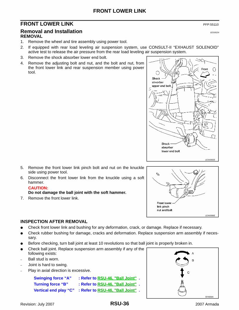
REMOVAL1. Remove the wheel and tire assembly using power tool.2. If equipped with rear load leveling air suspension system, use CONSULT-II “EXHAUST SOLENOID”
active test to release the air pressure from the rear load leveling air suspension system.3. Remove the shock absorber lower end bolt.4. Remove the adjusting bolt and nut, and the bolt and nut, from
the front lower link and rear suspension member using powertool.
5. Remove the front lower link pinch bolt and nut on the knuckleside using power tool.
6. Disconnect the front lower link from the knuckle using a softhammer.CAUTION:Do not damage the ball joint with the soft hammer.
7. Remove the front lower link.
INSPECTION AFTER REMOVAL● Check front lower link and bushing for any deformation, crack, or damage. Replace if necessary.● Check rubber bushing for damage, cracks and deformation. Replace suspension arm assembly if neces-
sary.● Before checking, turn ball joint at least 10 revolutions so that ball joint is properly broken in.● Check ball joint. Replace suspension arm assembly if any of the
following exists:– Ball stud is worn.– Joint is hard to swing.– Play in axial direction is excessive.
LEIA0082E
LEIA0086E
Swinging force “A” : Refer to RSU-46, "Ball Joint" .Turning force “B” : Refer to RSU-46, "Ball Joint" .Vertical end play “C” : Refer to RSU-46, "Ball Joint" .
SFA858A
FRONT LOWER LINK
RSU-37
C
D
F
G
H
I
J
K
L
M
A
B
RSU
Revision: July 2007 2007 Armada
INSTALLATIONInstallation is in the reverse order of removal.● Tighten the nuts and bolts to specification. Refer to RSU-24, "Components" .● Perform final tightening of nuts and bolts for the links (rubber bushing) under unladen condition (unladen
condition means that the fuel tank, engine coolant and lubricants are at the full specification, and thespare tire, jack, hand tools, and mats are in their designated positions) with the tires on level ground.
● Check the wheel alignment. Refer to RSU-26, "Wheel Alignment Inspection" .
RSU-38
REAR LOWER LINK & COIL SPRING
Revision: July 2007 2007 Armada
REAR LOWER LINK & COIL SPRING PFP:551B0
Removal and Installation EES002I5
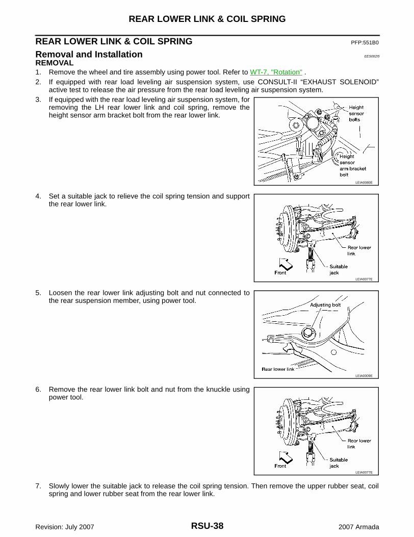
REMOVAL1. Remove the wheel and tire assembly using power tool. Refer to WT-7, "Rotation" .2. If equipped with rear load leveling air suspension system, use CONSULT-II “EXHAUST SOLENOID”
active test to release the air pressure from the rear load leveling air suspension system.3. If equipped with the rear load leveling air suspension system, for
removing the LH rear lower link and coil spring, remove theheight sensor arm bracket bolt from the rear lower link.
4. Set a suitable jack to relieve the coil spring tension and supportthe rear lower link.
5. Loosen the rear lower link adjusting bolt and nut connected tothe rear suspension member, using power tool.
6. Remove the rear lower link bolt and nut from the knuckle usingpower tool.
7. Slowly lower the suitable jack to release the coil spring tension. Then remove the upper rubber seat, coilspring and lower rubber seat from the rear lower link.
LEIA0080E
LEIA0077E
LEIA0009E
LEIA0077E
REAR LOWER LINK & COIL SPRING
RSU-39
C
D
F
G
H
I
J
K
L
M
A
B
RSU
Revision: July 2007 2007 Armada
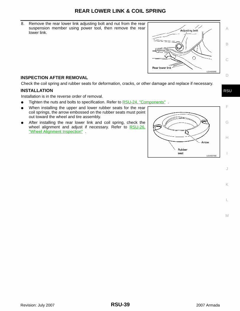
8. Remove the rear lower link adjusting bolt and nut from the rearsuspension member using power tool, then remove the rearlower link.
INSPECTION AFTER REMOVALCheck the coil spring and rubber seats for deformation, cracks, or other damage and replace if necessary.
INSTALLATIONInstallation is in the reverse order of removal.● Tighten the nuts and bolts to specification. Refer to RSU-24, "Components" .● When installing the upper and lower rubber seats for the rear
coil springs, the arrow embossed on the rubber seats must pointout toward the wheel and tire assembly.
● After installing the rear lower link and coil spring, check thewheel alignment and adjust if necessary. Refer to RSU-26,"Wheel Alignment Inspection" .
LEIA0009E
LEIA0076E
RSU-40
STABILIZER BAR
Revision: July 2007 2007 Armada
STABILIZER BAR PFP:56230
Removal and Installation EES002I6
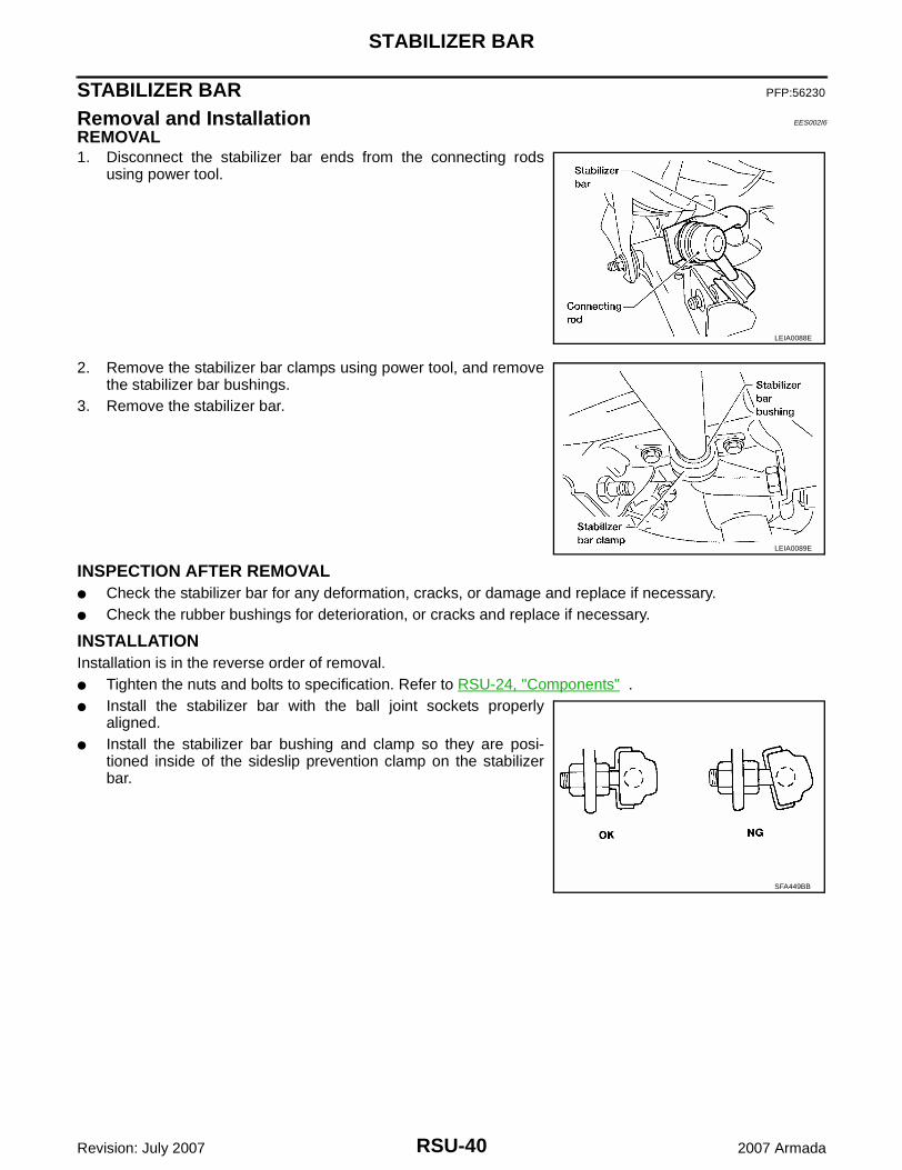
REMOVAL1. Disconnect the stabilizer bar ends from the connecting rods
using power tool.
2. Remove the stabilizer bar clamps using power tool, and removethe stabilizer bar bushings.
3. Remove the stabilizer bar.
INSPECTION AFTER REMOVAL● Check the stabilizer bar for any deformation, cracks, or damage and replace if necessary.● Check the rubber bushings for deterioration, or cracks and replace if necessary.
INSTALLATIONInstallation is in the reverse order of removal.● Tighten the nuts and bolts to specification. Refer to RSU-24, "Components" .● Install the stabilizer bar with the ball joint sockets properly
aligned.● Install the stabilizer bar bushing and clamp so they are posi-
tioned inside of the sideslip prevention clamp on the stabilizerbar.
LEIA0088E
LEIA0089E
SFA449BB
REAR LOAD LEVELING AIR SUSPENSION COMPRESSOR ASSEMBLY
RSU-41
C
D
F
G
H
I
J
K
L
M
A
B
RSU
Revision: July 2007 2007 Armada
REAR LOAD LEVELING AIR SUSPENSION COMPRESSOR ASSEMBLY PFP:53400
Removal and Installation EES002I7
Rear Load Leveling Air Suspension System
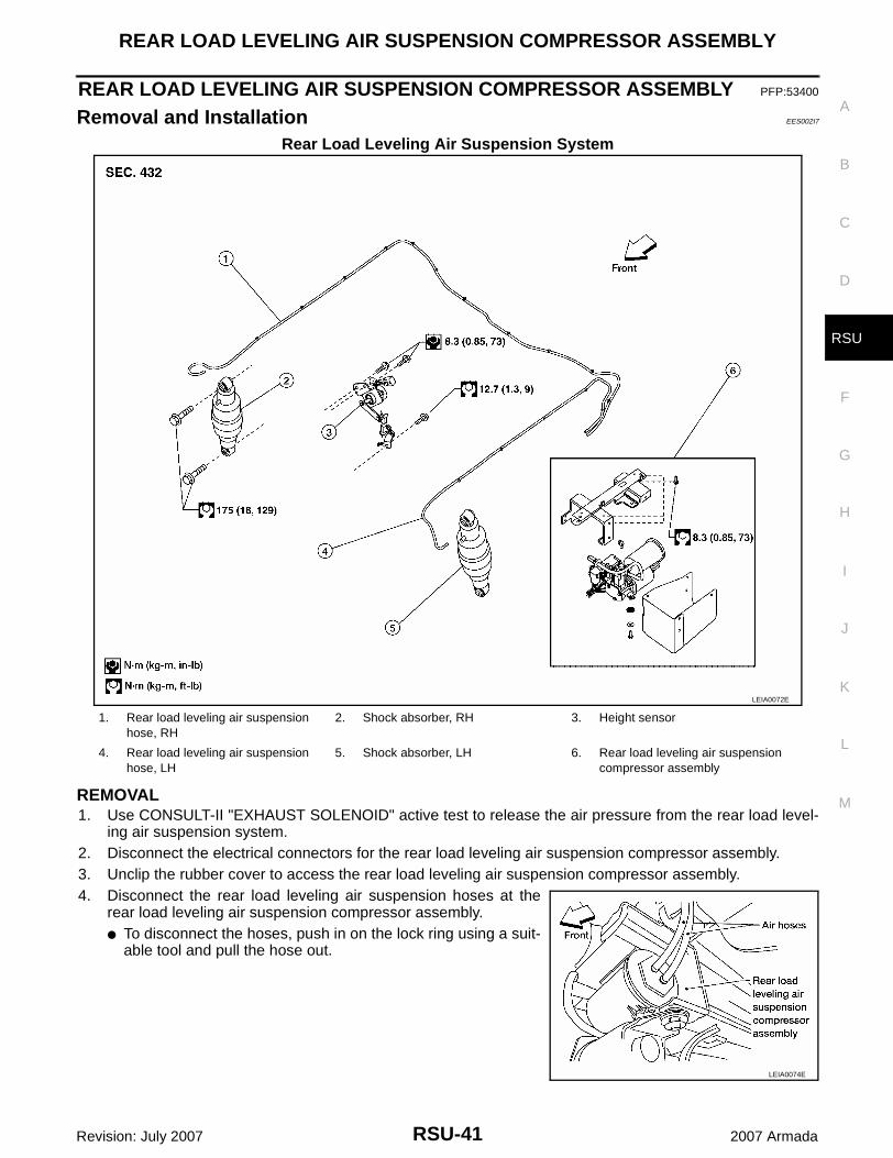
REMOVAL1. Use CONSULT-II "EXHAUST SOLENOID" active test to release the air pressure from the rear load level-
ing air suspension system.2. Disconnect the electrical connectors for the rear load leveling air suspension compressor assembly.3. Unclip the rubber cover to access the rear load leveling air suspension compressor assembly.4. Disconnect the rear load leveling air suspension hoses at the
rear load leveling air suspension compressor assembly.● To disconnect the hoses, push in on the lock ring using a suit-
able tool and pull the hose out.
LEIA0072E
1. Rear load leveling air suspension hose, RH
2. Shock absorber, RH 3. Height sensor
4. Rear load leveling air suspension hose, LH
5. Shock absorber, LH 6. Rear load leveling air suspension compressor assembly
LEIA0074E
RSU-42
REAR LOAD LEVELING AIR SUSPENSION COMPRESSOR ASSEMBLY
Revision: July 2007 2007 Armada
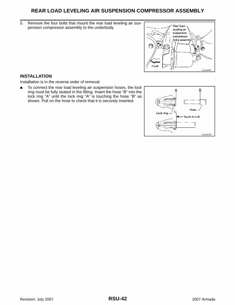
5. Remove the four bolts that mount the rear load leveling air sus-pension compressor assembly to the underbody.
INSTALLATIONInstallation is in the reverse order of removal.● To connect the rear load leveling air suspension hoses, the lock
ring must be fully seated in the fitting. Insert the hose “B” into thelock ring “A” until the lock ring “A” is touching the hose “B” asshown. Pull on the hose to check that it is securely inserted.
LEIA0090E
LEIA0078E
HEIGHT SENSOR
RSU-43
C
D
F
G
H
I
J
K
L
M
A
B
RSU
Revision: July 2007 2007 Armada
HEIGHT SENSOR PFP:53820
Removal and Installation EES002I8
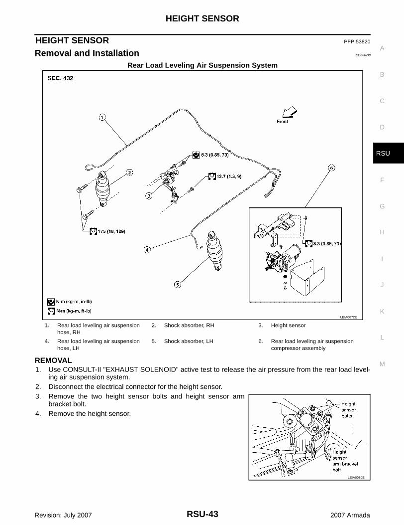
Rear Load Leveling Air Suspension System
REMOVAL1. Use CONSULT-II "EXHAUST SOLENOID" active test to release the air pressure from the rear load level-
ing air suspension system.2. Disconnect the electrical connector for the height sensor.3. Remove the two height sensor bolts and height sensor arm
bracket bolt.4. Remove the height sensor.
LEIA0072E
1. Rear load leveling air suspension hose, RH
2. Shock absorber, RH 3. Height sensor
4. Rear load leveling air suspension hose, LH
5. Shock absorber, LH 6. Rear load leveling air suspension compressor assembly
LEIA0080E
RSU-44
HEIGHT SENSOR
Revision: July 2007 2007 Armada
INSTALLATIONInstallation is in the reverse order of removal.1. Start the engine.2. Use CONSULT-II to perform "STANDARD HEIGHT LEVEL" work support function.3. Using data monitor of CONSULT-II, verify "HEIGT CALC" is at 0 mm.
4. Check the vehicle height. Refer to RSU-47, "Wheelarch Height (Unladen*1 )" . If vehicle height is notwithin ± 10 mm (0.39 in) of the specification, perform the initialization procedure. Refer to RSU-45, "Initial-ization Procedure" .
CONTROL UNIT
RSU-45
C
D
F
G
H
I
J
K
L
M
A
B
RSU
Revision: July 2007 2007 Armada
CONTROL UNIT PFP:47850
Removal and Installation EES002I9
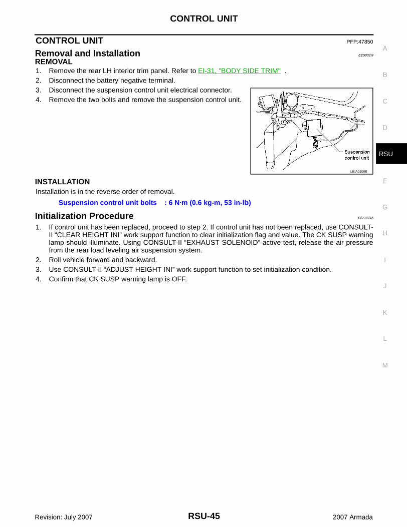
REMOVAL1. Remove the rear LH interior trim panel. Refer to EI-31, "BODY SIDE TRIM" .2. Disconnect the battery negative terminal.3. Disconnect the suspension control unit electrical connector.4. Remove the two bolts and remove the suspension control unit.
INSTALLATIONInstallation is in the reverse order of removal.
Initialization Procedure EES002IA
1. If control unit has been replaced, proceed to step 2. If control unit has not been replaced, use CONSULT-II “CLEAR HEIGHT INI” work support function to clear initialization flag and value. The CK SUSP warninglamp should illuminate. Using CONSULT-II “EXHAUST SOLENOID” active test, release the air pressurefrom the rear load leveling air suspension system.
2. Roll vehicle forward and backward.3. Use CONSULT-II “ADJUST HEIGHT INI” work support function to set initialization condition.4. Confirm that CK SUSP warning lamp is OFF.
LEIA0100E
Suspension control unit bolts : 6 N·m (0.6 kg-m, 53 in-lb)
RSU-46
SERVICE DATA AND SPECIFICATIONS (SDS)
Revision: July 2007 2007 Armada
SERVICE DATA AND SPECIFICATIONS (SDS) PFP:00030
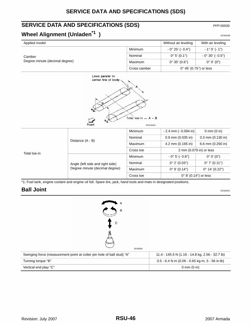
Wheel Alignment (Unladen*1 ) EES002IB
*1: Fuel tank, engine coolant and engine oil full. Spare tire, jack, hand tools and mats in designated positions.
Ball Joint EES002IC
Applied model Without air leveling With air leveling
CamberDegree minute (decimal degree)
Minimum - 0° 25′ (- 0.4°) - 1° 0′ (- 1°)
Nominal 0° 5′ (0.1°) - 0° 30′ (- 0.5°)
Maximum 0° 35′ (0.6°) 0° 0′ (0°)
Cross camber 0° 45' (0.75°) or less
Total toe-in
Distance (A - B)
Minimum - 2.4 mm (- 0.094 in) 0 mm (0 in)
Nominal 0.9 mm (0.035 in) 3.3 mm (0.130 in)
Maximum 4.2 mm (0.165 in) 6.6 mm (0.260 in)
Cross toe 2 mm (0.079 in) or less
Angle (left side and right side)Degree minute (decimal degree)
Minimum - 0° 5' (- 0.8°) 0° 0' (0°)
Nominal 0° 2' (0.03°) 0° 7' (0.11°)
Maximum 0° 9' (0.14°) 0° 14' (0.22°)
Cross toe 0° 8' (0.14°) or less
SFA234AC
Swinging force (measurement point at cotter pin hole of ball stud) “A” 11.4 - 145.5 N (1.16 - 14.8 kg, 2.56 - 32.7 lb)
Turning torque “B” 0.5 - 6.4 N·m (0.06 - 0.65 kg-m, 5 - 56 in-lb)
Vertical end play “C” 0 mm (0 in)
SFA858A
SERVICE DATA AND SPECIFICATIONS (SDS)
RSU-47
C
D
F
G
H
I
J
K
L
M
A
B
RSU
Revision: July 2007 2007 Armada
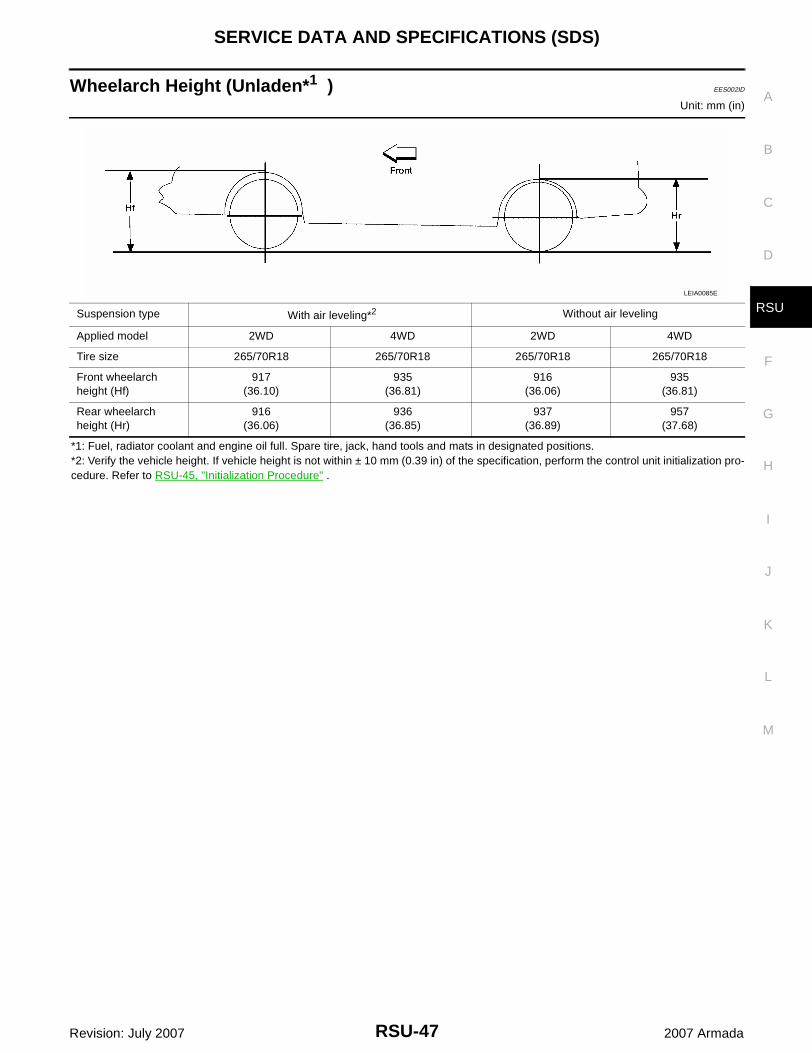
Wheelarch Height (Unladen*1 ) EES002ID
Unit: mm (in)
*1: Fuel, radiator coolant and engine oil full. Spare tire, jack, hand tools and mats in designated positions.*2: Verify the vehicle height. If vehicle height is not within ± 10 mm (0.39 in) of the specification, perform the control unit initialization pro-cedure. Refer to RSU-45, "Initialization Procedure" .
Suspension type With air leveling*2 Without air leveling
Applied model 2WD 4WD 2WD 4WD
Tire size 265/70R18 265/70R18 265/70R18 265/70R18
Front wheelarch height (Hf)
917(36.10)
935(36.81)
916(36.06)
935(36.81)
Rear wheelarch height (Hr)
916(36.06)
936(36.85)
937(36.89)
957(37.68)
LEIA0085E
RSU-48
SERVICE DATA AND SPECIFICATIONS (SDS)
Revision: July 2007 2007 Armada